Embed Size (px)
Citation preview

ELTROPLAN-REVCON Elektrotechnische Anlagen GmbH
Operating instructions
Power feedback unit REVCON RHD
Power range 4 ... 400 kW
Voltage range 230V, 400V, 460V,
500V, 690V
V 1.3 Issue 13/09

Contents
Operating instructions RHD 1
ELTROPLAN - REVCON
Elektrotechnische Anlagen GmbH
1 Preface and general information ............................................................................................ 3
1.1 About these Operating Instructions ....................................................................................... 3
1.1.1 Terminology used .................................................................................................................. 3
1.1.2 Ordering code ....................................................................................................................... 4
1.1.3 Scope of delivery ................................................................................................................... 4
1.1.4 Product selection ................................................................................................................... 5
1.1.5 Legal regulations ................................................................................................................... 6
2 EC-Directives / Declaration of conformity ............................................................................... 7
2.1 EC-Low-Voltage Directive ....................................................................................................... 7
2.2 EC-directive Electromagnetic compatibility ............................................................................ 8
2.3 EC-directive Machinery .......................................................................................................... 9
3 Safety information .............................................................................................................. 10
3.1 General safety information .................................................................................................. 11
3.2 Safety-responsible persons .................................................................................................. 15
3.3 Layout of the safety information .......................................................................................... 16
3.4 Residual hazards .................................................................................................................. 16
3.5 General instructions ............................................................................................................ 17
4 Technical data ..................................................................................................................... 28
4.1 Characteristics ..................................................................................................................... 28
4.2 General data/ application conditions ................................................................................... 29
4.3 Rated data .......................................................................................................................... 30
4.3.1 Power feedback unit RHD B0/D0 .......................................................................................... 30
4.3.2 Power feedback unit RHD B1/D1 .......................................................................................... 31
5 Current load ........................................................................................................................ 32
5.1 Current load REVCON RHD B0/B1/D0/D1 ............................................................................. 32
5.2 Fuses and wire cross sections ............................................................................................... 35
5.2.1 Series fuses ......................................................................................................................... 35
5.3 Internal fuses ...................................................................................................................... 37
5.3.1 Internal fuses RHD B0/D0 .................................................................................................... 37
5.3.2 Internal fuses RHD B1 .......................................................................................................... 39
5.3.3 Internal fuses RHD D1 .......................................................................................................... 39
5.4 RFI-filter .............................................................................................................................. 40
5.4.1 RFI-filter RHD-B0/D0 ............................................................................................................ 40
5.4.2 RFI-filter RHD-B1 ................................................................................................................. 42
5.4.3 RFI-filter RHD-D1 ................................................................................................................. 42

Contents
2 Operating instructions RHD
ELTROPLAN - REVCON
Elektrotechnische Anlagen GmbH
5.5 Harmonic filter module RHF-RA ........................................................................................... 43
5.5.1 RHF-RA filter RHD-B0/D0 ..................................................................................................... 43
6 Installation .......................................................................................................................... 45
6.1 Dimensions REVCON RHD .................................................................................................... 46
6.2 RFI-filter .............................................................................................................................. 52
6.3 RHF-RA-filter ....................................................................................................................... 57
7 Electrical Installation ........................................................................................................... 62
7.1 Mains types / Mains characteristics ..................................................................................... 63
7.2 Connection .......................................................................................................................... 64
7.3 Power connection................................................................................................................ 64
7.3.1 Wiring schematic RHD B0/B1/D0 ......................................................................................... 66
7.3.2 Wiring schematic RHD B0/D0 and FC with RHF-RA ................................................................ 68
7.3.3 Wiring schematic RHD B0/D0 with RHF-RA ........................................................................... 70
7.4 Fan supply ........................................................................................................................... 72
7.5 Control wires ....................................................................................................................... 72
7.6 Control functions ................................................................................................................. 72
7.7 Application example ............................................................................................................ 76
7.8 Installation of a power feedback unit in a CE-typical drive system ......................................... 77
8 Installation .......................................................................................................................... 79
8.1 Connection of a RFI-filter ..................................................................................................... 80
8.2 Design of an EMC-conformal cabinet .................................................................................... 81
8.3 Remarks .............................................................................................................................. 82
8.4 Installation of control wires ................................................................................................. 83
9 Commissioning .................................................................................................................... 84
9.1 First powering up ................................................................................................................ 84
10 Configuration ...................................................................................................................... 85
11 Troubleshooting and fault elimination ................................................................................. 88
11.1 LED-messages ...................................................................................................................... 89
12 Service ................................................................................................................................ 91
13 Appendix ............................................................................................................................. 92
13.1 Options ............................................................................................................................... 92
14 REVCON® Product overview ................................................................................................. 94
15 Contact ............................................................................................................................... 95

Preface and general information
Operating instructions RHD 3
ELTROPLAN - REVCON
Elektrotechnische Anlagen GmbH
1 Preface and general information
1.1 About these Operating Instructions
• These Operating Instructions help you to work properly on and with the power feed-
back units REVCON
RHD. They contain safety information which must be observed
and information which are necessary for an undisturbed operation of the units together
with the exploitation of all the advantages of the system.
• All persons who work on and with the power feedback units REVCON
RHD must
have the Operation instructions available and observe all relevant notes and instruc-
tion.
• The Operating Instructions must always be in a complete and perfectly readable state.
1.1.1 Terminology used
Power feedback unit
For „Power feedback unit „REVCON
RHD“ in the following the term „Power feedback
unit“ is used.
Controller
For the frequency inverter which is used together with the power feedback unit in the fol-
lowing the term „Controller“ is used.
Drive system
For a drive system with power feedback units, controller and other components of the drive
system in the following the term „Drive system“ is used.

Preface and general information
4 Operating instructions RHD
ELTROPLAN - REVCON
Elektrotechnische Anlagen GmbH
1.1.2 Ordering code
1.1.3 Scope of delivery
• 1 Power feedback unit REVCON
RHD
• 1 Operating instructions
• After receipt of the delivery verify immediately, if the scope of supply correspond
to the shipping documents. We make no warranty for later complained defects
Claim
• Visible transport damages in transit immediately at the deliverer.
• Visible deficiencies/incompleteness immediately to ELTROPLAN-REVCON.
RHD B0 033 - 400 - 50 - 0 - A
B
• Level B: With internal mains inductance
033
• Nominal feedback
power: e.g. 33kW
50
• Mains frequency:
e.g. 50Hz
A
• Version: A
RLD
• Product type:
REVCON- High Duty
For up to 100% duty
cycle
0 400
• Connection voltage:
e.g. 400VAC
0
• Auxiliary voltage:
0=Not required
• 0: Without integrated
harmonic filter
400V
1: With integrated
harmonic filter
•
Level D: With internal mains inductance
and additional DC capacity
•
Preface and general information
Operating instructions RHD 5
ELTROPLAN - REVCON
Elektrotechnische Anlagen GmbH
1.1.4 Product selection
Selection REVCON RHD B or D:
→ REVCON Type RHD B is sufficient for drives with direct DC-Bus connection.
→ REVCON Type RHD D is required for drives with DC-Bus connection.via the DC-
choke(s). This unit contains additional capacity to compensate the magnetic energy from
the DC choke in case of a system shutdown.

Preface and general information
6 Operating instructions RHD
ELTROPLAN - REVCON
Elektrotechnische Anlagen GmbH
1.1.5 Legal regulations
Labelling Nameplate CE-mark Manufacturer
Power feedback units REVCON
RHD
are unequivocally marked by the contents
of the nameplate.
Conforms the EC Low
Voltage Directive
ELTROPLAN-
REVCON
Edisonstraße 3
D-59199 Bönen
Patent rights The power feedback unit REVCON is protected in Germany and Europe by patents:
Patent-No.: DE 3938654C1 and Patent-Nr.: 90123584.6-2207.
Patent infringements become prosecute.
Application
as directed Power feedback unit REVCON
RHD
• Must only be operated under the conditions prescribed in these instructions.
• Are components
– to feedback electrical energy
– used for installation into a machine
– used for assembly together with other components to from a machine
• Are electric units for the installation into control cabinets or similar enclosed operating
housing.
• Comply with the requirements of the Low-Voltage Directive
• Are not machines for the purpose of the Machinery Directive
• Are not to be used as domestic appliances, but only for industrial purpose.
Drive systems with power feedback unit REVCON RHD
• Comply with the EMC-Directive if they are installed according to the guidelines of CE-typical
drive systems.
• Can be used
– on public and non-public mains
– in industrial as well as residential and commercial premises
• The user is responsible for the compliance of this application with the EC directives.
Liability • The information, data and notes in these Operating Instructions met the state of the art at the
time of printing. Claims referring to power feedback units which have already been supplied
cannot be derived from information, illustrations and descriptions given in these Operation In-
structions.
• The specifications, processes and circuitry described in these Operating Instructions are for
guidance only and must be adapted to your own specific application. ELTROPLAN-REVCON
does not take responsibility for the suitability of the process and circuit proposals.
• The indications given in these Operating Instructions describe the features of the product with-
out warranting them.
• ELTROPLAN-REVCON does not accept any liability for damage and operating interference
caused by:
– disregarding these instructions
– unauthorized modifications to the power feedback unit
– operating errors
– improper working on and with the power feedback unit
Warranty • Warranty conditions: see sales and delivery conditions of ELTROPLAN-REVCON GmbH.
• Warranty claims must be made immediately after detecting defects or faults.
• The warranty is void in all cases where liability claims cannot be made.
Disposal Material recycle disposal
Metal � -
Plastic � -
Printed-board assemblies - �

Preface and general information
Operating instructions RHD 7
ELTROPLAN - REVCON
Elektrotechnische Anlagen GmbH
2 EC-Directives / Declaration of conformity
What is the purpose of EC-Directives?
The EC-Directives have been drawn up by the European council to define common techni-
cal standards and certification procedures within the European Community. At the moment
there are 21 EC-Directives for product sectors. The directives are or will be converted in
national laws by the member states. If a certificate is conferred in one member state, it is
valid in all other member states automatically.
The directives only describe the basic standards. The technical details are or will be de-
scribed in harmonized European standards.
What is the meaning of the CE-marking?
After a conformity-assessment-procedure the conformity with the standards of the EC-
Directives is certified by fixing the CE-marking. Within the EC there are no trading obsta-
cles for a CE-marked product.
Power feedback units with CE-marking themselves are compliant with the Low-Voltage
Directive only. For observing the EMC Directive recommendations are made.
2.1 EC-Low-Voltage Directive
(73/23/EEC)
Modified by: CE – Marking Directive (93/68/EEC)
CE – Marking Directive (2006/95/EEC)
General:
• The Low-Voltage Directive is valid for all electrical equipment which is used at a nominal
voltage between 50V and 1000V AC and between 75V and 1500V DC together with cus-
tomary environment conditions. Excluded is e.g. the use of electrical equipment in explo-
sive areas and electrical components of lifts for persons or material.
• Aim of the Low-Voltage Directive is to put only those products into commerce which
don’t endanger the safety of persons and animals as well as the preservation of material as-
sets.

Preface and general information
8 Operating instructions RHD
ELTROPLAN - REVCON
Elektrotechnische Anlagen GmbH
EC-declaration of conformity
According to the EC-Low Voltage Directive (2006/95/EEC)
The power feedback units REVCON
RHD have been developed, designed and manu-
factured in accordance with the above mentioned EC-Directive and in sole responsibil-
ity of
ELTROPLAN-REVCON Elektrotechnische Anlagen GmbH,
Edisonstraße 3, D-59199 Bönen
Considered standards:
Standard
DIN VDE 0160 5.88 +A1 / 4.89 +A2 / 10.88
PRDIN EN 50178
Class VDE 0160 / 11.94
Equipment of power installations with
electronic components
EN 61558-1/A1 Safety of power transformers, power supplies,
reactors and similar products
EN 60529 International protection rating
DIN VDE 0100 Guidelines for the design of
power installations
2.2 EC-directive Electromagnetic compatibility
EMC directive (89/336/EWG)
Replaced by: EMC-directive (2004/108/EG)
General:
The objective target describes article 4 (2004/108/EG), as follows:
The... designated devices must be so manufactured, that
(a) an intended operation of radio- and telecommunication devices and other devices is
possible and
(b) the devices have an adequate stability against electromagnetically disturbances, so
that an intended operation is possible.

Preface and general information
Operating instructions RHD 9
ELTROPLAN - REVCON
Elektrotechnische Anlagen GmbH
EG-declaration by the manufacturer
in terms of the EG-standard EMC (2004/108/EG)
The listed REVCON
products are in terms of the EMC no independently recoverable
products, this means only after integration in the overall system would they be rateable
regarding to EMC. The rating became detected for typical plant constructions, but not for
the several products.
ELTROPLAN- REVCON Elektrotechnische Anlagen GmbH,
Edisonstraße 3, D-59199 Bönen
Considered standards: Standard
DIN EN 61000-3-3:2008
(IEC 61000-3-3:2008)
Generic standards Limits: Limitation of voltage changes, voltage fluctua-
tions and flicker in public low-voltage supply systems
DIN EN 61000-6-2:2005
(IEC 61000-6-2:2005)
Generic standards - Immunity for industrial environments
DIN EN 61000-6-3:2007 +A1:2011
(IEC 61000-6-3:2006+A1:2010)
Generic standards - Emission standard for residential, commercial and
light-industrial environments
DIN EN 61000-6-4:2007 + A1:2011
(IEC 61000-6-4:2006+A1:2010)
Generic standards - Emission standard for industrial environments
2.3 EC-directive Machinery
Machine directive (98/37/EG)
Changed by: Modification directive (2006/42/EG)
General:
Machinery means an assembly, fitted with or intended to be fitted with a drive system
other than directly applied human or animal effort, consisting of linked parts or compo-
nents, at least one of which moves, and which are joined together for a specific applica-
tion.
EC- declaration by the manufacturer in terms of the EG-directive machines (2006/42/EG)
The Energy feedback units REVCON
RHD were developed, designed and manufac-
tured in accordance to the above named EG- directive in exclusive accountability by
ELTROPLAN-REVCON Elektrotechnische Anlagen GmbH,
Edisonstraße 3, D-59199 Bönen
The operation of the Energy feedback units REVCON
RHD is prohibited as long as it is
determined, that the machine, in which it should be installed, conforms to the regulations
of the EG-directive machines.
Safety information
10 Operating instructions RHD
ELTROPLAN - REVCON
Elektrotechnische Anlagen GmbH
3 Safety information
Safety and application notes
for drive converters
(Low-Voltage Directive (2006/95/EEC)
1. General During operation, power feedback unit may have, according to their
type of protection, live, bare, in some cases also movable or rotating
parts as well as hot surfaces.
Non –authorized removal of required cover, inappropriate use, incor-
rect installation or operation, creates the risk of severe injury to per-
sons or damage to material assets.
Further information can be obtained from the documentation.
All operations concerning transport, installation and commissioning as
well as maintenance must be carried out by qualified, skilled person-
nel (IEC 364 and CENELEC HD 384 or DIN VDE 0100 and IEC-
Report 664 or DIN VDE 0110 and national regulations for the preven-
tions of accidents must be observed).
According to this basic safety information qualified skilled personnel
are persons who are familiar with the erection, assembly, commission-
ing and operation of the product and who have the qualifications nec-
essary for their occupation .
2. Application as directed
Power feedback units are components which are designed for installa-
tion in electrical systems or machinery.
When installing in machines, commissioning of the power feedback
unit (i.e. the starting of operation as directed) is prohibited until it is
proven, that the machine corresponds to the regulations of the EC Di-
rective (2006/42/EG) (Machinery Directive); EN 60204 must be ob-
served.
Commissioning (i.e. starting operation as directed) is only allowed
when there is compliance with the EMC-Directive (2004/108/EG).
The power feedback units meet the requirements of the Low-Voltage
Directive (2006/95/EEC). The harmonized standards of the prEN
50178/DIN VDE 0160 series together with EN 60439-1/DIN VDE
0660 part 500 and EN 60146/DIN VDE 0558 are applicable for the
power feedback unit. The technical data and information on the con-
nection conditions must be obtained from the nameplate and the
documentation and must be observed in all cases.
3. Transport, Storage
Notes on transport, storage and appropriate handling must be observed
At non-observance any warranty expires.
The power feedback unit has to be protected from inadmissible stress.
The transport is only valid in original packaging and in the thereon by
pictograms marked transport position.
In particular during transport and handling no components are allowed
to be bent and / or isolating distances may not be altered. The units are
equipped with electrostatic sensitive devices, which may be damaged
by improper handling. Therefore it has to be avoided to get in contact
with electronic components. If electronic components are damaged
mechanically the unit must not be put into operation, as it cannot be
ensured, that all relevant standards are observed. Climatic conditions
must be observed according to prEN 50178.
4. Erection The devices must be erected and cooled according to the regu-
lations of the corresponding documentation.
The power feedback units must be protected from inappropriate
loads. Particularly during transport and handling, components
must not be bent and / or isolating distances must not be
changed. Touching of electronic components and contacts must
be avoided.
Power feedback units contain electro-statically sensitive com-
ponents which can easily be damaged by inappropriate han-
dling. Electrical components must not be damaged or destroyed
mechanically (health risk are possible!).
5. Electrical Connection
When working on live power feedback units, the valid national
regulations for the prevention of accidents (e.g. VBG 4) must
be observed. Before any installation or connection works, the
plant has to be switched off and to be secured properly.
The electrical installation must be carried out according to the
appropriate regulations (e.g. cable cross-sections, fuses, PE-
connection). More detailed information is included in the
documentation. When using the power feedback unit with con-
trollers without safe separation from the supply line (to VDE
0100) all control wiring has to be include in further protective
measures (e.g. double insulated or shielded, grounded and insu-
lated).
Notes concerning the installation in compliance with EMC –
such as screening, grounding, arrangement of filters and lying
of cables – are included in the chapter installation of this docu-
mentation. These notes must be also observed in all cases for
power feedback units with the CE-mark. The compliance with
the required limit values demanded by the EMC legislation is
the responsibility of the manufacturer of the system or machine.
6. Operation
Systems where power feedback units are installed, if applicable,
have to be equipped with additional monitoring and protective
devices according to the valid safety regulations e.g. law on
technical tools, regulations for the prevention of accidents, etc. .
After disconnecting the power feedback unit from the supply
voltage, live parts of the power feedback unit and power con-
nections must not be touched immediately, because of possibly
charged capacitors. For this, observe the corresponding labels
on the drive controllers.
During operation, all covers and doors must be closed.
7. Maintenance and service
The manufacturer’s documentation must be observed.
This safety information must be kept!
The product-specific safety and application notes in these Op-
erating Instructions must also be observed!

Safety information
Operating instructions RHD 11
ELTROPLAN - REVCON
Elektrotechnische Anlagen GmbH
3.1 General safety information
• These safety regulations are not entitled to completeness. In case of questions please
contact our technicians.
• When commissioning the power feedback units are compliant with the state of the
art. The power feedback unit generally allows safe operation.
• The statements of this manual describe the attributes of the products without guaran-
teeing them.
• The power feedback unit may expose persons, the power feedback units itself and
other material to danger, if
– non qualified personal works at and with the power feedback unit.
– The power feedback unit is used in opposite to its purpose.
• Power feedback units have to be projected in a way, that they fulfil their function and
don’t expose persons to danger, if they are mounted correctly and are used in accor-
dance with their purpose. This applies also for the interplay with the whole plant.
• The units, operational data and circuit details described in this manual have to be un-
derstood analogously and have to be checked for transferability to each application.
• For the reasons of personal safety, the observance of the EMC-regulations and for
the regular cooling the operation of the device is only allowed with a closed cover of
the housing and with mounted flanges!
• Use the drive system only in flawless condition.

Safety information
12 Operating instructions RHD
ELTROPLAN - REVCON
Elektrotechnische Anlagen GmbH
• Modifications of the power feedback units without consultation of a REVCON
-
technician are not allowed generally.
• The warranty given by us expires, if the unit is modified or (even partially) dismantled
or if it is used in contradiction to our instructions.
• The constructor of the plant, who has to know the technical guidelines, bears the re-
sponsibility for the correct selection and arrangement of the electrical components.
• Putting into operation of the power feedback unit is only admissible at VDE-conform
nets of electrical power supply. Non observance may damage the device!
• In accordance with the corresponding standards and guidelines the operation on even
for a short time over-compensated networks (cosϕ≤1) respectively on un-choked com-
pensation-units is not admissible. If this is done nevertheless, overvoltage will occur
(caused by oscillating currents), which may damage all connected components, espe-
cially electronic units like controllers and power feedback units.
• To low powered or unloaded generators and to regulating transformers it is never al-
lowed to feed back power without a previous consultation of our application depart-
ment. Otherwise unintended voltage rises / excess voltages are generated, which may
damage or destroy REVCON
and combined units!
• Before operating at nets without reference to neutral ground additional safety meas-
ures (e.g. installation of over voltage suppressors like MOV’s) have to be done. If nec-
essary, please ask for technical support by our technicians.

Safety information
Operating instructions RHD 13
ELTROPLAN - REVCON
Elektrotechnische Anlagen GmbH
• An undisturbed operation of the power feedback unit is only probable, if the following
instructions are observed. If these instructions are not observed, tripping of the unit
and damages may occur.
• Pay attention to the correct values of mains and DC-bus voltage.
• Separate power and control wires (> 15cm)
• Use shielded or twisted control wires. Connect both ends of the shield to ground!
• When using the digital input devices, only use suitable switching devices, whose
contacts are able to switch the connected voltages.
• Connect the housings of drive, controller and power feedback unit to ground
carefully. Connect shields of power cables to ground at both ends with as big
surface as possible (remove lacquer)!
• Connect the cabinet or the plant by a star-shaped network to ground (ground
loops have to be avoided!)
• The power feedback unit has been designed for a fixed connection to mains only. Es-
pecially when using RFI-filter leakage current values> 3,5mA may occur. The cross
section of the earthing conductor must be at least 10mm² copper, or a second conduc-
tor has to be connected in parallel (star shaped grounding network).
• If components are used, which have no electrical separated inputs / outputs it is neces-
sary to equalize the potentials (e.g. by an equalizing wire). If this is not observed,
these components may be damaged by equalizing currents.
• When carrying out an insulations test in accordance with VDE0100/part 620 the de-
vice has to be disconnected to avoid damage to the power semiconductors. This proce-
dure corresponds with the standard, as each device performs a high voltage test in ac-
cordance with VDE 0160 (EN 50178) in the course of final testing after manufactur-
ing.
Safety information
14 Operating instructions RHD
ELTROPLAN - REVCON
Elektrotechnische Anlagen GmbH
• A standard fault-current circuit breaker (sensitive on peak currents) is not allowed to
be used as the only protective measure when using controller and power feedback unit
Caused by a DC-component in the mains current a controller with 3-phase input volt-
age may prevent a fault-current circuit breaker from tripping in case of a earth fault. In
accordance with VDE 0160 a fault-current circuit breaker is not allowed to be used as
the only protective measure. In dependence on the kind of network (TN, IT, TT) fur-
ther protective measures in accordance with VDE 0100 part 410 are necessary. For a
TN-network this may be an over current protection, for an IT-network insulation su-
pervision with pulscode-measurement. For all kind of networks protective insulation (-
transformer) may be used, if required power and length of wires allow that. When se-
lecting a fault current circuit breaker the following measures have to be considered:
• The fault current circuit breaker has to be compliant with the VDE 0664 standard.
• The tripping current should be 300mA or more, to prevent a premature tripping
caused by the leakage current of the controller. In dependence on the load, the
length of the motor cables and the usage of a RFI-filter the leakage current may
even be much higher.
Fault current circuit breakers, which are sensitive to all kinds of leakage currents, grant a
good protection and are suitable as the only protection measurement for one ore three
phase controllers. The connection instructions of the manufacturer have to be observed.
Safety information
Operating instructions RHD 15
ELTROPLAN - REVCON
Elektrotechnische Anlagen GmbH
3.2 Safety-responsible persons
User
• User is any natural or legal entity, who uses the drive system or by whom order the
drive system is used.
• The user respectively his security officer have to grant
– that all relevant regulations, instructions and laws have to be observed
– that only qualified personnel works with or at the drive system
– that the relevant manual is available for the personnel during any works
– that non-qualified personnel is prohibited to work on the drive system
Qualified staff
Stop!
Qualified staff means persons, that are entitled (by the safety responsible) due to their training,
experience, education, their knowledge in relevant norms, directives, accident directives and op-
eration conditions to execute the necessary works and to recognize possible danger and to avoid
it. (Definition of qualified staff IEC 364)
Intended Use
Danger!
Power feedback units are electrical drive components, which are directed to be installed in
electrical plants or machines. They have to be used only for drive systems with infinity variable
speed controls of 3-phase asynchronous or permanent magnet motors. The usage with other elec-
trical loads is not permitted and may damage the devices. The power feedback unit may only be
connected to symmetrical networks. Non-observance may damage the devices.
STOP

Safety information
16
3.3 Layout of the s
• All safety no
- The icon c
- The signa
- The note d
Signal word Legend
Used pictogra
Warning of
injury to
persons
Imm
by c
War
mine
Dan
situa
War
surfa
Warning of
property
damages
Harm
situa
Useful informa-
tion and
application notes
Info
3.4 Residual hazar
Operator’s safety
After mains disconnections, th
Protection of the device
Cyclic connection and disconn
overload the internal input cur
Allow at least 1 minute betwee
STOP
STOP
Operating
ELTROPLAN - REVCO Elektrotechnische A
e safety information
notes have a uniform layout:
n characterizes the type of danger.
nal word characterizes the severity of danger.
te describes the danger and suggests how to avo
grams Signal words minent danger
current
Danger! Warns of an immediate
ger. Consequences by
Death or severe injurie
arning of a im-
inent danger Warning! Warns of a possible, ve
situation. Possible con
gard:
Death or severe injurie
angerous
tuation Caution!
Warns of a possible, da
Possible consequences
Minor or small injuries
arning of hot
rface Warning! Warns of touching a ho
Possible consequences
Burnings
armful
tuation Stop! Warns of possible prop
Possible consequences
Damage of the drive sy
roundings
formation Note!
Marks a generally, use
If you follow it, you m
handling of the system
ards
the power terminals + and – remain live for sev
nnection of the supply voltage at terminals L1,
urrent limitation:
een disconnection and reconnection.
instructions RHD
ON
Anlagen GmbH
void the danger.
iately imminent Dan-
y disregard:
ries
, very danger
onsequences by disre-
ries
, dangerous situation.
es by disregard:
ies
hot surface.
es by disregard:
roperty damages.
es by disregard:
system or its sur-
seful note, tip.
make the
m easier
several minutes.
1, L2 und L3, may
Safety information
Operating instructions RHD 17
ELTROPLAN - REVCON
Elektrotechnische Anlagen GmbH
3.5 General instructions
By this information to erectors and users of a plant hints on properties and directions con-
cerning the power feedback unit are given. These hints are not entitled to completeness.
Special features in comparison to a brake chopper:
Unlike a braking resistor a power feedback device isn't a constant drain, but it's dependent
on the momentary characteristics of the supplying net. Commutation brake downs and
voltage-flicker in the net have a considerable effect to the backward current of the device.
In case of a short time voltage brake down the backward current has to raise correspond-
ingly to feedback the demanded power-amount. Does the level of the supply voltage sink
for a longer time; the maximum feedback power is reduced.
If only one phase fails, the device is able to work on, but the current in the two remaining
conductors will rise up to 150% of the normal level.

Safety information
18 Operating instructions RHD
ELTROPLAN - REVCON
Elektrotechnische Anlagen GmbH
Length of the DC-connection
The maximum inductivity of the DC-connection between output B6- Bridge of the in-
verter and the power feedback device mustn't exceed a certain level, as this inductivity
inducts an additional voltage to the DC-bus, when the IGBT’s are switched off. To avoid
an overload to the components of the power feedback unit, this additional voltage must
not exceed 100V. Resulting from this and other relevant characteristics of the power
feedback unit (DC-capacity and absolute maximum value of the grid current) the maxi-
mum inductivity can be calculated.
This inductivity always has to be higher or equal than the sum of the DC-bus inductivity
of the frequency inverter and the conductor inductivity of the DC connection.
The DC-bus inductivity of the frequency inverter has only to be considered, if it is placed
between the inverter B6- Bridge and the power feed-back unit. The cables, which are
normally used for power applications, have an inductance per unit length of about
0,6µH/m. If the values of the input capacitance C, the during power feedback maximum
allowed rise of the DC-voltage ∆UGL =100V, the top level of the AC-current of the de-
vice
the inductance per unit length L´
and the inductance of the DC-bus ´choke LZKD are known the maximum longitude of the
conductors can be calculated with the following equation:
L
L
Li
UCl ZKDGL
′−
′⋅
∆⋅=
2
2
max ˆ
effIi ×= 2ˆ2( )2
2
maxi
UCL GL∆⋅
=
effIi ×=2ˆ2
( )25,0ln´ 0 +=⋅µ
ral
L π

Safety information
Operating instructions RHD 19
ELTROPLAN - REVCON
Elektrotechnische Anlagen GmbH
Typical capacitance of the DC-connection inside the power feedback unit:
REVCON®
-type Power
[kW]
DC-capacity
[µF]
RHD B0 400V 7 20
RHD B0 400V 13 20
RHD B0 400V 18 100
RHD B0 400V 24 40
RHD B0 400V 30 40
RHD B0 400V 50 220
RHD B0 400V 70 220
RHD B0 400V 100 660
RHD B0 400V 125 440
RHD B0 400V 150 660
RHD B0 400V 200 660
RHD B0 400V 250 880
Table 3.5.1
REVCON®
-type Power
[kW]
DC-capacity
[µF]
RHD D0 400V 8 100
RHD D0 400V 14 100
RHD D0 400V 19 100
RHD D0 400V 25 100
RHD D0 400V 31 100
RHD D0 400V 51 220
RHD D0 400V 71 440
RHD D0 400V 101 660
RHD D0 400V 126 660
RHD D0 400V 151 1760
RHD D0 400V 201 1760
RHD D0 400V 251 1980
Table 3.5.2
Example:
C=200µF, ∆UGL=100V, i=271A, a=80mm, r=8,5mm, µ0=1,257.10
-6 H/m
⇒ lmax=26m
For longer DC-Bus-wires additional capacitors have to be installed (please get in contact
with our application-department if the occasion arises).
( )25,0ln´ 0 +=⋅µ
ral
L πL
L
Li
UCl ZKDGL
′−
′⋅
∆⋅=
2
2
max ˆ

Safety information
20 Operating instructions RHD
ELTROPLAN - REVCON
Elektrotechnische Anlagen GmbH
Operation on a generator
The usage of a power feedback unit within an isolated network (e.g. with a diesel genera-
tor) is possible, but there are restrictive regulations concerning the power limits.
M
M
REVCON
R
0,4kV 100kVA
20kW 20kW
G
FC
Figure 3.5.1
Within a network that is assembled like in figure 3.5.1 there are two additional restric-
tions: First the power of the motor connected to the inverter must be lower than half of
the nominal power of the generator. Second the total amount of the power of the two
other loads must be more than double of the feedback power.
If these conditions aren't checked up a change from motor to generator operation may re-
sult in load shocks. These shocks are too dynamic for the voltage regulator of the genera-
tor. The regulator reacts with an overshoot and as a result of this with an over voltage
within the island network.
Danger!
Over voltages may cause serious damages to the connected frequency inverter and /or to the
power feedback unit and to the other loads.

Safety information
Operating instructions RHD 21
ELTROPLAN - REVCON
Elektrotechnische Anlagen GmbH
Operation on a transformer
Is the energy balance of an installation negative (i.e. even for short periods more braking
energy is fed in as the other loads in the same mains section collect), the nominal (com-
plex) power of the transformer must be at least 1,5 times higher than the in this section
fed back (real) power, to be even able to transfer the harmonic- and reactive ratio of the
currents.
Generally the short circuit voltage of the transformer should be preferably small (typical
4-6%).
Danger!
At non-observance of these connecting conditions overvoltage and mains voltage harmonic dis-
tortions are generated, which can lead to damages at the power feedback units and other con-
nected components!
Die above-named conditions are in the in figure 2.6.2 diagrammed mains section just ob-
served, if the other loads are switched off.
M
M R
Tr 10kV 0,4kV
100kVA
60kW
20kW 20kW
FC
REVCON
Figure 3.5.2
The mains impedance of all installed feedback units should be 2 times so large as the
mains impedance, but minimum the 1,5-times of the mains impedance!

Safety information
22 Operating instructions RHD
ELTROPLAN - REVCON
Elektrotechnische Anlagen GmbH
Placing of the commutation choke
If the frequency converter is connected to an external commutation choke, the connection
of the power feedback unit has to be done at its network terminals (figure 2.6.3). Is the
connection done at the load terminals of the commutation choke its inductivity prevents the
synchronising to the supplying net and the induction voltage of the choke when it is
switched of under load may result in damages to the power feedback device.
Danger!
Over voltages may cause serious damages to the connected frequency inverter and /or to the
power feedback unit and to the other loads.
REVCON
M 60kW
FC
Mains supply
Not allowed!
Figure 3.5.3
The same things apply to the also non-admissible pre-connection of further commutation
chokes.

Safety information
Operating instructions RHD 23
ELTROPLAN - REVCON
Elektrotechnische Anlagen GmbH
Line and contact resistances
The values of current carrying capacity of conductors refer to the most often used copper
conductors. Concerning to its higher specific resistance aluminium conductors must have
greater dimensions.
Regardless of which conducting material is used, the contact terminals of the conductors
have to be low resistive and their number has to be reduced to the necessary minimum.
Too much or too high resistive terminals may result in an unsafe voltage magnification
during the power feedback operation.
M
FC
∆U ∆U ∆U ∆U ∆U ∆U ∆U I
Supplying
network
REVCON
Figure 3.5.4
Proceeding from a stable network with e.g. 400V nominal voltage and a backward current
of 80A, at a bad made terminal of 100mW a voltage of 8V is dropped (a good made ter-
minal has got a resistance of ca 1 mW.). During feedback operation at seven serial termi-
nals at the net switch results a voltage of 456V.

Safety information
24 Operating instructions RHD
ELTROPLAN - REVCON
Elektrotechnische Anlagen GmbH
Danger!
Over voltages may cause serious damages to the connected frequency converter and /or to the
power feedback unit and to the other loads.
Current capacity of copper conductors for frequency converters and power feed-
back operation:
Wire cross- section
[mm²]
Conductor radius
[mm]
Fuse
[A]
Max. continuous current
[A]
16 2,3 63 46
25 2,8 80 59
35 3,3 100 73
50 4,0 125 90
70 4,7 160 106
95 5,5 200 140
120 6,2 250 206
185 7,7 315 250
2x120 2x6,2 400 300
2x150 2x6,9 500 390
2x185 2x7,7 630 485
3x185 3x7,7 800 570
3x240 3x8,7 1000 740
4x240 4x8,7 1250 920 These values are based on a cable length of 100m and a maximum voltage drop of 5V.
Table 3.5.5

Safety information
Operating instructions RHD 25
ELTROPLAN - REVCON
Elektrotechnische Anlagen GmbH
Connection of further loads
The connection of further loads (e.g. cabinet ventilation or air conditioning) parallel to the
frequency inverter / power feedback unit at a common circuit breaker like in figure 2.6.5 is
not allowed. If it's done nevertheless, in case of tripping of the circuit breaker the connec-
tion to the network (energy sink and synchronising element for the power feedback unit)
misses. The IGBT's now switch the DC-voltage directly to the other loads. The resulting
nearly rectangular "net"-voltage drives a current through the loads, which level and form
depends on their impedance. Is the power consumption of the loads to small, the DC-
voltage and also the output voltage of the power feedback unit rises during the feedback
operation. This increased voltage may damage all connected components.
M 60kW
FC
Supplying network
M
Right
False
REVCON
Figure 3.5.6
Danger!
Over voltages may cause serious damages to the connected controller and /or to the power feed-
back unit and to the other loads.

Safety information
26 Operating instructions RHD
ELTROPLAN - REVCON
Elektrotechnische Anlagen GmbH
M 60kW
FC
Supplying network
M
FC
M
FC
REVCON
Figure 3.5.7
Note!
Same things apply to the structure like in figure 3.5.7. Even in this case it is necessary to place a
circuit breaker in each feedback current circuit.
Safety information
Operating instructions RHD 27
ELTROPLAN - REVCON
Elektrotechnische Anlagen GmbH
Unchoked compensation plants and resonance rise
Compensation plants are used in the centre of the power supply of a company. Distur-
bances or damages at these plants have effects on the power supply and may result in inter-
rupted production processes.
Although this is no longer state of the art, many compensation plants are in operation with-
out any choking. The problems which result from a usage of such an unchoked compensa-
tion plant are manifold:
- direct resonance
- resonance rise
- switching transients or
- impairments of centralized ripple systems
The fact, that a company produces back effects to the power supply is not the only reason
for the creation of resonance. Decisive for the risk, to generate a resonance is the compen-
sation power at the medium voltage transformer. The higher this power is so higher is the
risk of resonance. The second important factor is the harmonic load of the medium voltage
level. This harmonic load is transmitted via the transformer and causes effects on the low
voltage level. Most often the limits were exceeded for the 5th harmonic component.

Technical data
28 Operating instructions RHD
ELTROPLAN - REVCON
Elektrotechnische Anlagen GmbH
4 Technical data
4.1 Characteristics
• Small compact housing
• Braking power of controller is fed back into mains
• Power range 4kW to 250kW
• Units can be paralleled (on request)
• DC-bus coupling of several controllers possible
• IGBT power modules with high efficiency and high service reliability
• Self synchronising
• Overload protection during feedback operation
• Supervision of mains voltage, phase sequence and temperature
• High efficiency
• High dynamic braking processes are possible
• User-friendly commissioning – no adjustment necessary
Technical data
Operating instructions RHD 29
ELTROPLAN - REVCON
Elektrotechnische Anlagen GmbH
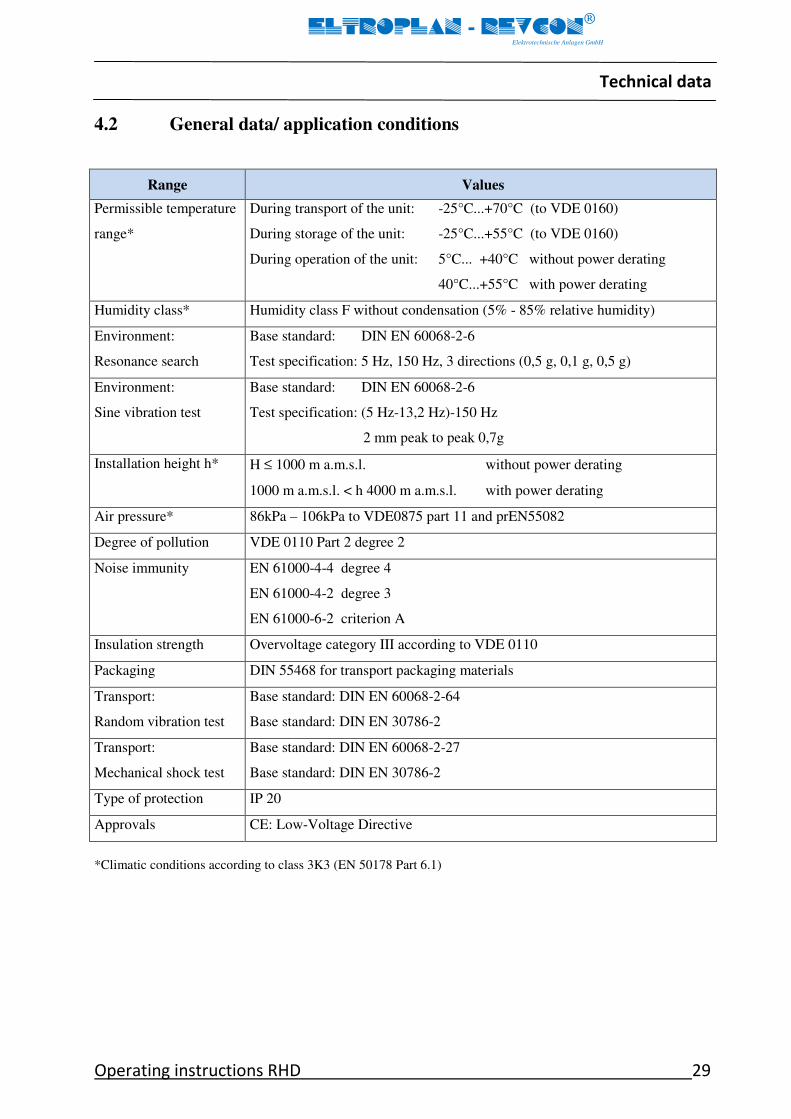
4.2 General data/ application conditions
Range Values
Permissible temperature
range*
During transport of the unit: -25°C...+70°C (to VDE 0160)
During storage of the unit: -25°C...+55°C (to VDE 0160)
During operation of the unit: 5°C... +40°C without power derating
40°C...+55°C with power derating
Humidity class* Humidity class F without condensation (5% - 85% relative humidity)
Environment:
Resonance search
Base standard: DIN EN 60068-2-6
Test specification: 5 Hz, 150 Hz, 3 directions (0,5 g, 0,1 g, 0,5 g)
Environment:
Sine vibration test
Base standard: DIN EN 60068-2-6
Test specification: (5 Hz-13,2 Hz)-150 Hz
2 mm peak to peak 0,7g
Installation height h* H ≤ 1000 m a.m.s.l. without power derating
1000 m a.m.s.l. < h 4000 m a.m.s.l. with power derating
Air pressure* 86kPa – 106kPa to VDE0875 part 11 and prEN55082
Degree of pollution VDE 0110 Part 2 degree 2
Noise immunity EN 61000-4-4 degree 4
EN 61000-4-2 degree 3
EN 61000-6-2 criterion A
Insulation strength Overvoltage category III according to VDE 0110
Packaging DIN 55468 for transport packaging materials
Transport:
Random vibration test
Base standard: DIN EN 60068-2-64
Base standard: DIN EN 30786-2
Transport:
Mechanical shock test
Base standard: DIN EN 60068-2-27
Base standard: DIN EN 30786-2
Type of protection IP 20
Approvals CE: Low-Voltage Directive
*Climatic conditions according to class 3K3 (EN 50178 Part 6.1)
Technical data
30 Operating instructions RHD
ELTROPLAN - REVCON
Elektrotechnische Anlagen GmbH
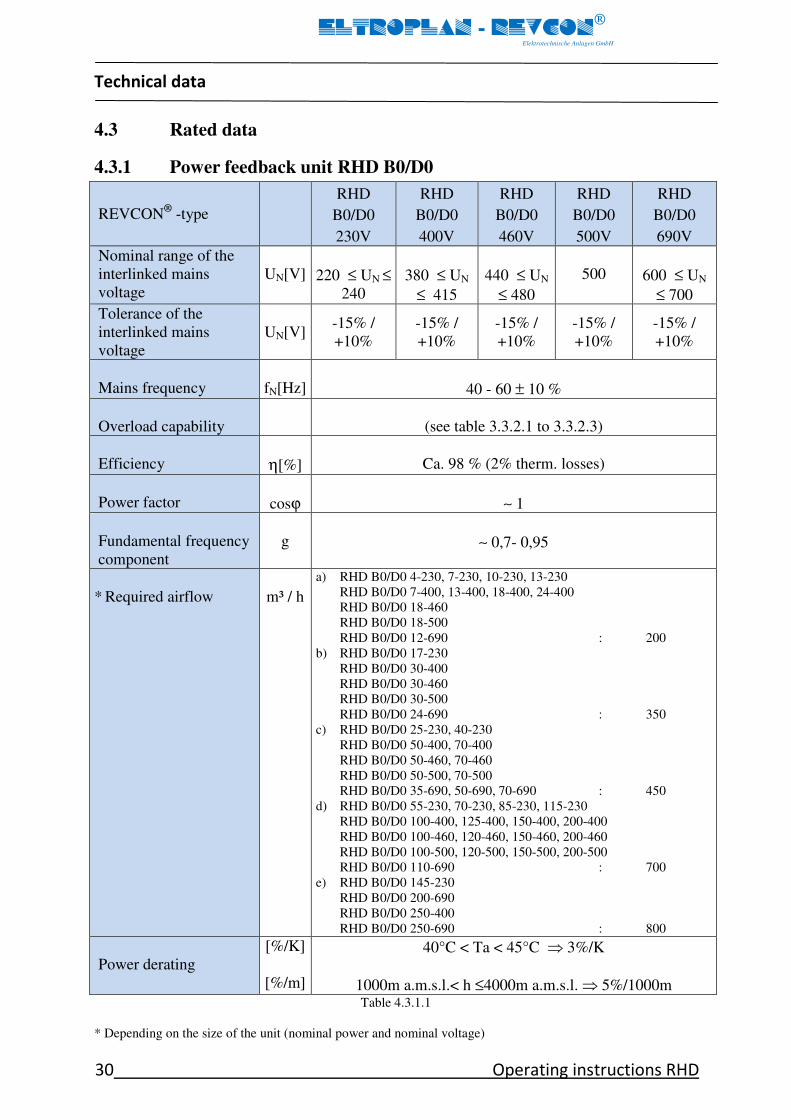
4.3 Rated data
4.3.1 Power feedback unit RHD B0/D0
REVCON®
-type
RHD
B0/D0
230V
RHD
B0/D0
400V
RHD
B0/D0
460V
RHD
B0/D0
500V
RHD
B0/D0
690V
Nominal range of the
interlinked mains
voltage
UN[V]
220 ≤ UN ≤
240
380 ≤ UN
≤ 415
440 ≤ UN
≤ 480
500
600 ≤ UN
≤ 700
Tolerance of the
interlinked mains
voltage
UN[V] -15% /
+10%
-15% /
+10%
-15% /
+10%
-15% /
+10%
-15% /
+10%
Mains frequency
fN[Hz]
40 - 60 ± 10 %
Overload capability
(see table 3.3.2.1 to 3.3.2.3)
Efficiency
η[%]
Ca. 98 % (2% therm. losses)
Power factor
cosϕ
∼ 1
Fundamental frequency
component
g
∼ 0,7- 0,95
* Required airflow
m³ / h
a) RHD B0/D0 4-230, 7-230, 10-230, 13-230
RHD B0/D0 7-400, 13-400, 18-400, 24-400
RHD B0/D0 18-460
RHD B0/D0 18-500
RHD B0/D0 12-690 : 200
b) RHD B0/D0 17-230
RHD B0/D0 30-400
RHD B0/D0 30-460
RHD B0/D0 30-500
RHD B0/D0 24-690 : 350
c) RHD B0/D0 25-230, 40-230
RHD B0/D0 50-400, 70-400
RHD B0/D0 50-460, 70-460
RHD B0/D0 50-500, 70-500
RHD B0/D0 35-690, 50-690, 70-690 : 450
d) RHD B0/D0 55-230, 70-230, 85-230, 115-230
RHD B0/D0 100-400, 125-400, 150-400, 200-400
RHD B0/D0 100-460, 120-460, 150-460, 200-460
RHD B0/D0 100-500, 120-500, 150-500, 200-500
RHD B0/D0 110-690 : 700
e) RHD B0/D0 145-230
RHD B0/D0 200-690
RHD B0/D0 250-400
RHD B0/D0 250-690 : 800
Power derating
[%/K]
[%/m]
40°C < Ta < 45°C ⇒ 3%/K
1000m a.m.s.l.< h ≤4000m a.m.s.l. ⇒ 5%/1000m
Table 4.3.1.1
* Depending on the size of the unit (nominal power and nominal voltage)

Technical data
Operating instructions RHD 31
ELTROPLAN - REVCON
Elektrotechnische Anlagen GmbH
4.3.2 Power feedback unit RHD B1/D1
REVCON®
-type
RHD B1/D1 400V
Nominal range of the
interlinked mains
voltage
UN[V]
380 ≤ UN ≤ 415
Tolerance of the
interlinked mains
voltage
UN[V] -15% / +10%
Mains frequency
fN[Hz]
40 - 60 ± 10 %
Overload capability
(see table 3.3.2.1 to 3.3.2.3)
Efficiency
η[%]
Ca. 98 % (2% therm. losses)
Power factor
cosϕ
∼ 1
Fundamental frequency
component
g
∼ 0,7- 0,95
* Required airflow
m³ / h
a) RHD B1/D1 7-230, 10-230, 13-230, 24-400 : 200
b) RHD B1/D1 30-400 : 350
Power derating
[%/K]
[%/m]
40°C < Ta < 45°C ⇒ 3%/K
1000m a.m.s.l.< h ≤4000m a.m.s.l. ⇒ 5%/1000m
Table 4.3.2.1
* Depending on the size of the unit (nominal power and nominal voltage)
Technical data
32 Operating instructions RHD
ELTROPLAN - REVCON
Elektrotechnische Anlagen GmbH
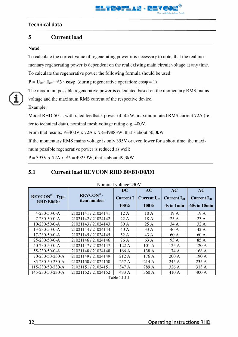
5 Current load
Note!
To calculate the correct value of regenerating power it is necessary to note, that the real mo-
mentary regenerating power is dependent on the real existing main circuit voltage at any time.
To calculate the regenerative power the following formula should be used:
P = Ueff · Ieff · √3 · cosϕϕϕϕ (during regenerative operation: cosϕ = 1)
The maximum possible regenerative power is calculated based on the momentary RMS mains
voltage and the maximum RMS current of the respective device.
Example:
Model RHD-50-... with rated feedback power of 50kW, maximum rated RMS current 72A (re-
fer to technical data), nominal mesh voltage rating e.g. 400V.
From that results: P=400V x 72A x √3=49883W, that’s about 50,0kW
If the momentary RMS mains voltage is only 395V or even lower for a short time, the maxi-
mum possible regenerative power is reduced as well:
P = 395V x·72A x √3 = 49259W, that’s about 49,3kW.
5.1 Current load REVCON RHD B0/B1/D0/D1
Nominal voltage 230V
REVCON® - Type
RHD B0/D0
REVCON®
-
item number
DC
Current I
100%
AC
Current Ieff
100%
AC
Current Ieff
4s in 1min
AC
Current Ieff
60s in 10min
4-230-50-0-A 21021141 / 21024141 12 A 10 A 19 A 19 A
7-230-50-0-A 21021142 / 21024142 22 A 18 A 25 A 23 A
10-230-50-0-A 21021143 / 21024143 30 A 25 A 34 A 32 A
13-230-50-0-A 21021144 / 21024144 40 A 33 A 46 A 42 A
17-230-50-0-A 21021145 / 21024145 52 A 43 A 60 A 60 A
25-230-50-0-A 21021146 / 21024146 76 A 63 A 93 A 85 A
40-230-50-0-A 21021147 / 21024147 122 A 101 A 125 A 120 A
55-230-50-0-A 21021148 / 21024148 166 A 138 A 174 A 168 A
70-230-50-230-A 21021149 / 21024149 212 A 176 A 200 A 190 A
85-230-50-230-A 21021150 / 21024150 257 A 214 A 245 A 235 A
115-230-50-230-A 21021151 / 21024151 347 A 289 A 326 A 313 A
145-230-50-230-A 21021152 / 21024152 433 A 360 A 410 A 400 A Table 5.1.1.1

Technical data
Operating instructions RHD 33
ELTROPLAN - REVCON
Elektrotechnische Anlagen GmbH
Nominal voltage 400V
REVCON® - Type
RHD B0/D0
REVCON® -
item number
DC
Current I
100%
AC
Current Ieff
100%
AC
Current Ieff
4s in 1min
AC
Current Ieff
60s in 10min
7-400-50-0-A 21021001 /21024001 12 A 10 A 19 A 19 A
13-400-50-0-A 21021002 / 21024002 23 A 19 A 25 A 23 A
18-400-50-0-A 21021003 / 21024003 31 A 26 A 34 A 32 A
24-400-50-0-A 21021004 / 21024004 42 A 35 A 46 A 42 A
30-400-50-230-A 21021005 / 21024005 52 A 43 A 60 A 60 A
50-400-50-230-A 21021006 / 21024006 87 A 72 A 93 A 85 A
70-400-50-230-A 21021007 / 21024007 122 A 101 A 125 A 120 A
100-400-50-230-A 21021008 / 21024008 174 A 144 A 174 A 168 A
125-400-50-230-A 21021009 / 21024009 218 A 180 A 200 A 190 A
150-400-50-230-A 21021010 / 21024010 260 A 217 A 245 A 235 A
200-400-50-230-A 21021011 / 21024011 347 A 289 A 326 A 313 A
250-400-50-230-A 21021012 / 21024012 433 A 360 A 410 A 400 A Table 5.1.1.2
Nominal voltage 460V
REVCON® - Type
RHD B0/D0
REVCON® -
item number
DC
Current I
100%
AC
Current Ieff
100%
AC
Current Ieff
4s in 1min
AC
Current Ieff
60s in 10min
18-460-60-0-A 21021021 / 21024021 26 A 22 A 28 A 25 A
30-460-60-115-A 21021022 / 21024022 45 A 38 A 48 A 44 A
50-460-60-115-A 21021023 / 21024023 76 A 63 A 76 A 73 A
70-460-60-115-A 21021024 / 21024024 106 A 88 A 106 A 98 A
100-460-60-115-A 21021025 / 21024025 151 A 126 A 151 A 140 A
120-460-60-115-A 21021026 / 21024026 181 A 151 A 181 A 168 A
150-460-60-115-A 21021027 / 21024027 226 A 188 A 240 A 230 A
200-460-60-115-A 21021028 / 21024028 304 A 251 A 300 A 300 A
250-460-60-115-A 21021029 / 21024029 378 A 313 A 375 A 375 A Table 5.1.1.3
Nominal voltage 500V
REVCON® - Type
RHD B0/D0
REVCON® -
item number
DC
Current I
100%
AC
Current Ieff
100%
AC
Current Ieff
4s in 1min
AC
Current Ieff
60s in 10min
18-500-50-0-A 21021121 / 21024121 25 A 21 A 27 A 25 A
30-500-50-230-A 21021122 / 21024122 42 A 35 A 44 A 41 A
50-500-50-230-A 21021123 / 21024123 70 A 58 A 70 A 65 A
70-500-50-230-A 21021124 / 21024124 98 A 81 A 98 A 90 A
100-500-50-230-A 21021125 / 21024125 140 A 116 A 140 A 129 A
120-500-50-230-A 21021126 / 21024126 167 A 139 A 167 A 155 A
150-500-50-230-A 21021127 / 21024127 208 A 173 A 205 A 190 A
200-500-50-230-A 21021128 / 21024128 280 A 231 A 270 A 255 A Table 5.1.1.4

Technical data
34 Operating instructions RHD
ELTROPLAN - REVCON
Elektrotechnische Anlagen GmbH
Nominal voltage 690V
REVCON® - Type
RHD B0/D0
REVCON® -
item number
DC
Current I
100%
AC
Current Ieff
100%
AC
Current Ieff
4s in 1min
AC
Current Ieff
60s in 10min
12-690-50-230-A 21021061 / 21024061 12 A 10 A 13 A 12 A
24-690-50-230-A 21021062 / 21024062 24 A 20 A 26 A 24 A
35-690-50-230-A 21021063 / 21024063 36 A 30 A 39 A 36 A
50-690-50-230-A 21021064 / 21024064 50 A 42 A 54 A 50 A
70-690-50-230-A 21021065 / 21024065 71 A 59 A 78 A 71 A
110-690-50-230-A 21021066 / 21024066 111 A 92 A 125 A 110 A
150-690-50-230-A 21021067 / 21024067 151 A 126 A 160 A 151 A
200-690-50-230-A 21021068 / 21024068 202 A 167 A 217 A 209 A
250-690-50-230-A 21021069 / 21024069 253 A 209 A 265 A 250 A Table 5.1.1.5
Nominal voltage 400V
REVCON® - Type
RHD B1
REVCON® -
item number
DC
Current I
100%
AC
Current Ieff
100%
AC
Current Ieff
4s in 1min
AC
Current Ieff
60s in 10min
7-400-50-0-A 21022001 15 A 10 A 13 A 12
13-400-50-0-A 21022002 23 A 19 A 25 A 23
24-400-50-0-A 21022004 42 A 35 A 46 A 42
30-400-50-230-A 21022005 60 A 43 A 56 A 52
Table 5.1.1.6
Nominal voltage 400V
REVCON® - Type
RHD D1
REVCON® -
item number
DC
Current I
100%
AC
Current Ieff
100%
AC
Current Ieff
4s in 1min
AC
Current Ieff
60s in 10min
7-400-50-0-A 21025001 15 A 10 A 13 A 12
13-400-50-0-A 21025002 23 A 19 A 25 A 23
24-400-50-0-A 21025004 42 A 35 A 46 A 42
30-400-50-230-A 21025005 60 A 43 A 56 A 52
Table 5.1.1.7

Technical data
Operating instructions RHD 35
ELTROPLAN - REVCON
Elektrotechnische Anlagen GmbH
5.2 Fuses and wire cross sections
The power feed/feedback unit is connected to mains supply via the terminals L1-L3 at the
terminal plate. Mains fuses must be designed according to the current load capacity of the
supply wire.
5.2.1 Series fuses
Semiconductor fuses have to be connected in series with the power feedback unit as fol-
lowing tables (refer to figure 4.4.1.1.1 position 1). The listed manufacturer is recom-
mended, but naturally also comparative fuses of other manufacturer (e.g. Jean Müller, Fer-
raz, and Bussmann) are suitable.
REVCON®
- type
RHD B0/D0
Max. fuse AC
Connection terminal and
max. cross section of the
supply line*
4-230-50-0-A Siba 5012406.20 20A 690V 10x38mm ES 25mm²
7-230-50-0-A Siba 5017906.30 30A 690V 14x51mm ES 25mm²
10-230-50-0-A Siba 5012406.50 50A 690V 14x51mm ES 25mm²
13-230-50-0-A Siba 5014006.80 80A 690V 22x58mm ES 25mm²
17-230-50-0-A Siba 5014006.80 80A 690V 22x58mm ES 25mm²
25-230-50-0-A Siba 5014006.100 100A 690V 22x58mm ES 25mm²
40-230-50-0-A Siba 2018920.200 200A 690V NH 00 ES 50mm²
55-230-50-0-A Siba 2018920.315 315A 690V NH 00 ES 150mm²
70-230-50-230-A Siba 2018920.350 350A 690V NH 00 ES 150mm²
85-230-50-230-A Siba 2071332.400 400A 1100V NH 1 ES 150mm²
115-230-50-230-A Siba 2071332.500 500A 1100V NH 1 ES 240mm²
145-230-50-230-A Siba 2071332.630 630A 1100V NH 1 ES 240mm² Table 5.2.1.1
REVCON®
- type
RHD B0/D0
Max. fuse AC
Connection terminal and
max. cross section of the
supply line*
7-400-50-0-A Siba 5012406.20 20A 690V 10x38mm ES 25mm²
13-400-50-0-A Siba 5017906.30 30A 690V 14x51mm ES 25mm²
18-400-50-0-A Siba 5012406.50 50A 690V 14x51mm ES 25mm²
24-400-50-0-A Siba 5014006.80 80A 690V 22x58mm ES 25mm²
30-400-50-230-A Siba 5014006.80 80A 690V 22x58mm ES 25mm²
50-400-50-230-A Siba 2018920.160 160A 690V NH 00 ES 25mm²
70-400-50-230-A Siba 2018920.160 160A 690V NH 00 ES 50mm²
100-400-50-230-A Siba 2018920.250 250A 690V NH 00 ES 150mm²
125-400-50-230-A Siba 2018920.315 315A 690V NH 00 ES 150mm²
150-400-50-230-A Siba 2071332.400 400A 1100V NH 1 ES 150mm²
200-400-50-230-A Siba 2071332.500 500A 1100V NH 1 ES 240mm²
250-400-50-230-A Siba 2071332.630 630A 1100V NH 1 ES 240mm² Table 5.2.1.2

Technical data
36 Operating instructions RHD
ELTROPLAN - REVCON
Elektrotechnische Anlagen GmbH
REVCON®
- type
RHD B0/D0
Max. fuse AC
Connection terminal and
max. cross section of the
supply line*
18-460-60-0-A Siba 5012406.50 50A 690V 14x51mm ES 25mm²
30-460-60-115-A Siba 5014006.80 80A 690V 22x58mm ES 25mm²
50-460-60-115-A Siba 5007406.125 125A 690V 22x58mm ES 25mm²
70-460-60-115-A Siba 2018920.160 160A 690V NH 00 ES 50mm²
100-460-60-115-A Siba 2018920.250 250A 690V NH 00 ES 150mm²
120-460-60-115-A Siba 2018920.315 315A 690V NH 00 ES 150mm²
150-460-60-115-A Siba 2018920.350 350A 690V NH 00 ES 150mm²
200-460-60-115-A Siba 2071332.400 400A 1100V NH 1 ES 240mm²
250-460-60-115-A Siba 2071332.500 500A 1100V NH 1 ES 240mm² Table 5.2.1.3
REVCON®
- type
RHD B0/D0
Max. fuse AC
Connection terminal and
max. cross section of the
supply line*
18-500-50-0-A Siba 5012406.50 50A 690V 14x51mm ES 25mm²
30-500-50-230-A Siba 5014006.80 80A 690V 22x58mm ES 25mm²
50-500-50-230-A Siba 5007406.125 125A 690V 22x58mm ES 25mm²
70-500-50-230-A Siba 2018920.160 160A 690V NH 00 ES 50mm²
100-500-50-230-A Siba 2018920.250 250A 690V NH 00 ES 150mm²
120-500-50-230-A Siba 2018920.250 250A 690V NH 00 ES 150mm²
150-500-50-230-A Siba 2018920.350 350A 690V NH 00 ES 150mm²
200-500-50-230-A Siba 2071332.400 400A 1100V NH 1 ES 240mm² Table 5.2.1.4
REVCON®
- type
RHD B0/D0
Max. fuse AC
Connection terminal and
max. cross section of the
supply line*
12-690-50-230-A Siba 50124 34.20 20A 690 V 14x51mm ES 25mm²
24-690-50-230-A Siba 50140 06.32 32A 690 V 22x58mm ES 25mm²
35-690-50-230-A Siba 50140 06.50 50A 690 V 22x58mm ES 25mm²
50-690-50-230-A Siba 50140 06.63 63A 690 V 22x58mm ES 25mm²
70-690-50-230-A Siba 50140 06.80 80A 690 V 22x58mm ES 25mm²
110-690-50-230-A Siba 50140 06.135 135A 690 V 22x58mm ES 25mm²
150-690-50-230-A Siba 20189 20.200 200A 690V NH 00 ES 150mm²
200-690-50-230-A Siba 20189 20.250 250A 690V NH 00 ES 150mm²
250-690-50-230-A Siba 20189 20.315 315A 690V NH 00 ES 150mm² Table 5.2.1.5
Table 5.2.1.6
REVCON® - Type
RHD B1
Max. fuse AC
Connection terminal and
max. cross section of the
supply line*
7-400-50-0-A Siba 5012406.20 20A 690V 10x38mm AE 25mm²
13-400-50-0-A Siba 5017906.30 30A 690V 14x51mm AE 25mm²
24-400-50-0-A Siba 5012406.50 50A 690V 14x51mm AE 25mm²
30-400-50-230-A Siba 5014006.80 80A 690V 22x58mm AE 25mm²

Technical data
Operating instructions RHD 37
ELTROPLAN - REVCON
Elektrotechnische Anlagen GmbH
Table 5.2.1.7
ES ≅ End sleeve for strands
* At the fuse holder respective disconnector
5.3 Internal fuses
The power feedback unit is equipped with semiconductor fuses according to the follow-
ing tables (refer to figure 4.4.1.1.1. position 7). The listed manufacturer is recommended,
but naturally also comparative fuses of other manufacturer (e.g. Jean Müller, Ferraz, and
Bussmann) are suitable.
Stop!
If semiconductor fuses (figure 4.4.1.1.1 position 1 and 7) trip, please get in contact with EL-
TROPLAN-REVCON immediately, as possibly further protective measures have tripped. If in-
ternal fuses are exchanged, please verify that only the original types are used for replacement.
Danger!
Before replacing a fuse, switch off all voltages!
5.3.1 Internal fuses RHD B0/D0
REVCON®
- type
DC-fuses
(use fast acting semiconductor fuses only)
RHD B0/D0 4-230-50-0-A Siba 5012406.20 20A 690V 14x51mm
RHD B0/D0 7-230-50-0-A Siba 5012406.32 32A 690V 14x51mm
RHD B0/D0 10-230-50-0-A Siba 5012406.50 50A 690V 14x51mm
RHD B0/D0 13-230-50-0-A Siba 5014006.63 63A 690V 22x58mm
RHD B0/D0 17-230-50-0-A Siba 5014006.80 80A 690V 22x58mm
RHD B0/D0 25-230-50-0-A Siba 5014206.135 135A 690V 22x58mm
RHD B0/D0 40-230-50-0-A Siba 2018920.200 200A 660V NH 00
RHD B0/D0 55-230-50-0-A Siba 2018920.250 250A 690V NH 00
RHD B0/D0 70-230-50-230-A Siba 2018920.315 315A 690V NH 00
RHD B0/D0 85-230-50-230-A Siba 2018920.400 400A 690V NH 00
RHD B0/D0 115-230-50-230-A Siba 2071332.630 630A 1110V NH 1
RHD B0/D0 145-230-50-230-A Siba 2072332.800 800A 1100V NH 2 Table 5.3.1.1
REVCON® - Type
RHD D1
Max. fuse AC
Connection terminal and
max. cross section of the
supply line*
7-400-50-0-A Siba 5012406.20 20A 690V 10x38mm AE 25mm²
13-400-50-0-A Siba 5017906.30 30A 690V 14x51mm AE 25mm²
24-400-50-0-A Siba 5012406.50 50A 690V 14x51mm AE 25mm²
30-400-50-230-A Siba 5014006.80 80A 690V 22x58mm AE 25mm²
STOP

Technical data
38 Operating instructions RHD
ELTROPLAN - REVCON
Elektrotechnische Anlagen GmbH
REVCON®
- type
DC-fuses
(use fast acting semiconductor fuses only)
RHD B0/D0 7-400-50-0-A Siba 5012406.20 20A 690 V 14x51mm
RHD B0/D0 13-400-50-0-A Siba 5012406.32 32A 690 V 14x51mm
RHD B0/D0 18-400-50-0-A Siba 5012406.50 50A 690 V 14x51mm
RHD B0/D0 24-400-50-0-A Siba 5014006.63 63A 690 V 22x58mm
RHD B0/D0 30-400-50-230-A Siba 5014006.80 80A 690 V 22x58mm
RHD B0/D0 50-400-50-230-A Siba 5014206.135 135A 600 V 22x58mm
RHD B0/D0 70-400-50-230-A Siba 2018920.200 200A 690V NH 00
RHD B0/D0 100-400-50-230-A Siba 2018920.250 250A 690V NH 00
RHD B0/D0 125-400-50-230-A Siba 2018920.315 315A 690V NH 00
RHD B0/D0 150-400-50-230-A Siba 2018920.400 400A 690V NH 00
RHD B0/D0 200-400-50-230-A Siba 2071332.500 500A 1110 V NH 1
RHD B0/D0 250-400-50-230-A Siba 2072332.800 800A 1100 V NH 2 Table 5.3.1.2
REVCON®
- type
DC-fuses
(use fast acting semiconductor fuses only)
RHD B0/D0 18-460-60-0-A Siba 5012406.50 50A 690V 14x51mm
RHD B0/D0 30-460-60-115-A Siba 5014006.100 100A 690V 22x58mm
RHD B0/D0 50-460-60-115-A Siba 5014006.100 100A 690V 22x58mm
RHD B0/D0 70-460-60-115-A Siba 2018920.160 160A 690V NH 00
RHD B0/D0 100-460-60-115-A Siba 2018920.250 250A 690V NH 00
RHD B0/D0 120-460-60-115-A Siba 2018920.315 315A 690V NH 00
RHD B0/D0 150-460-60-115-A Siba 2018920.400 400A 690V NH 00
RHD B0/D0 200-460-60-115-A Siba 2071332.500 500A 1110V NH 1
RHD B0/D0 250-460-60-115-A Siba 2071332.500 500A 1110V NH 1 Table 5.3.1.3
REVCON®
- type
DC-fuses
(use fast acting semiconductor fuses only)
RHD B0/D0 18-500-50-0-A Siba 5012406.50 50A 690V 14x51mm
RHD B0/D0 30-500-50-230-A Siba 5014006.100 100A 690V 22x58mm
RHD B0/D0 50-500-50-230-A Siba 5014206.135 135A 690V 22x58mm
RHD B0/D0 70-500-50-230-A Siba 2018920.160 160A 690V NH 00
RHD B0/D0 100-500-50-230-A Siba 2018920.250 250A 690V NH 00
RHD B0/D0 120-500-50-230-A Siba 2018920.315 315A 690V NH 00
RHD B0/D0 150-500-50-230-A Siba 2018920.400 400A 690V NH 00
RHD B0/D0 200-500-50-230-A Siba 2071332.630 630A 1110V NH 1 Table 5.3.1.3
Technical data
Operating instructions RHD 39
ELTROPLAN - REVCON
Elektrotechnische Anlagen GmbH
REVCON®
- type
DC-fuses
(use fast acting semiconductor fuses only)
RHD B0/D0 12-690-50-230-A Siba 5012406.50 50A 690V 14x51mm
RHD B0/D0 24-690-50-230-A Siba 5012406.50 50A 690V 14x51mm
RHD B0/D0 35-690-50-230-A Siba 5014006.63 63A 690V 22x58mm
RHD B0/D0 50-690-50-230-A Siba 5014006.80 80A 690V 22x58mm
RHD B0/D0 70-690-50-230-A Siba 5014206.135 135A 690V 22x58mm
RHD B0/D0 110-690-50-230-A Siba 2018920.160 160A 690V NH 00
RHD B0/D0 150-690-50-230-A Siba 2018920.200 200A 690V NH 00
RHD B0/D0 200-690-50-230-A Siba 2071332.315 315A 1250V NH 1
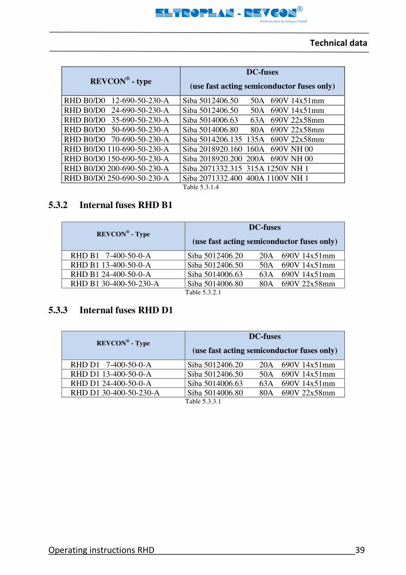
RHD B0/D0 250-690-50-230-A Siba 2071332.400 400A 1100V NH 1 Table 5.3.1.4
5.3.2 Internal fuses RHD B1
Table 5.3.2.1
5.3.3 Internal fuses RHD D1
Table 5.3.3.1
REVCON® - Type
DC-fuses
(use fast acting semiconductor fuses only)
RHD B1 7-400-50-0-A Siba 5012406.20 20A 690V 14x51mm RHD B1 13-400-50-0-A Siba 5012406.50 50A 690V 14x51mm RHD B1 24-400-50-0-A Siba 5014006.63 63A 690V 14x51mm RHD B1 30-400-50-230-A Siba 5014006.80 80A 690V 22x58mm
REVCON® - Type
DC-fuses
(use fast acting semiconductor fuses only)
RHD D1 7-400-50-0-A Siba 5012406.20 20A 690V 14x51mm RHD D1 13-400-50-0-A Siba 5012406.50 50A 690V 14x51mm RHD D1 24-400-50-0-A Siba 5014006.63 63A 690V 14x51mm RHD D1 30-400-50-230-A Siba 5014006.80 80A 690V 22x58mm
Technical data
40 Operating instructions RHD
ELTROPLAN - REVCON
Elektrotechnische Anlagen GmbH
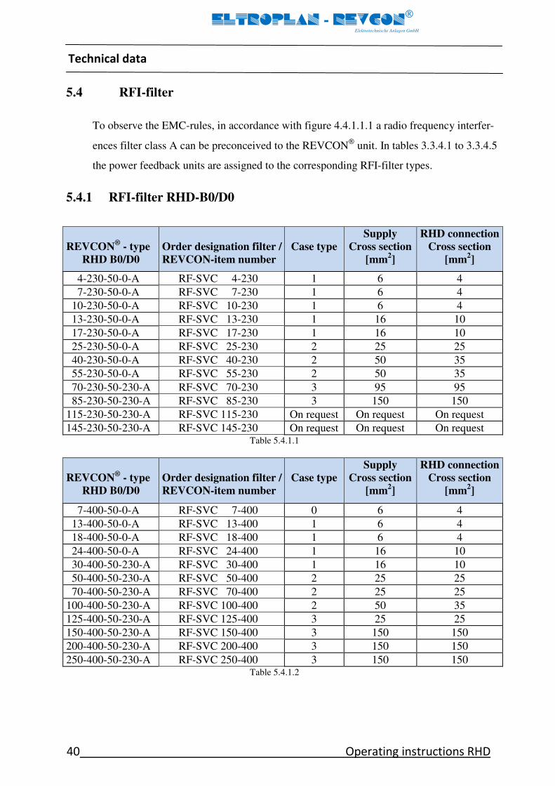
5.4 RFI-filter
To observe the EMC-rules, in accordance with figure 4.4.1.1.1 a radio frequency interfer-
ences filter class A can be preconceived to the REVCON
unit. In tables 3.3.4.1 to 3.3.4.5
the power feedback units are assigned to the corresponding RFI-filter types.
5.4.1 RFI-filter RHD-B0/D0
REVCON®
- type
RHD B0/D0
Order designation filter /
REVCON-item number
Case type
Supply
Cross section
[mm2]
RHD connection
Cross section
[mm2]
4-230-50-0-A RF-SVC 4-230 1 6 4
7-230-50-0-A RF-SVC 7-230 1 6 4
10-230-50-0-A RF-SVC 10-230 1 6 4
13-230-50-0-A RF-SVC 13-230 1 16 10
17-230-50-0-A RF-SVC 17-230 1 16 10
25-230-50-0-A RF-SVC 25-230 2 25 25
40-230-50-0-A RF-SVC 40-230 2 50 35
55-230-50-0-A RF-SVC 55-230 2 50 35
70-230-50-230-A RF-SVC 70-230 3 95 95
85-230-50-230-A RF-SVC 85-230 3 150 150
115-230-50-230-A RF-SVC 115-230 On request On request On request
145-230-50-230-A RF-SVC 145-230 On request On request On request Table 5.4.1.1
REVCON®
- type
RHD B0/D0
Order designation filter /
REVCON-item number
Case type
Supply
Cross section
[mm2]
RHD connection
Cross section
[mm2]
7-400-50-0-A RF-SVC 7-400 0 6 4
13-400-50-0-A RF-SVC 13-400 1 6 4
18-400-50-0-A RF-SVC 18-400 1 6 4
24-400-50-0-A RF-SVC 24-400 1 16 10
30-400-50-230-A RF-SVC 30-400 1 16 10
50-400-50-230-A RF-SVC 50-400 2 25 25
70-400-50-230-A RF-SVC 70-400 2 25 25
100-400-50-230-A RF-SVC 100-400 2 50 35
125-400-50-230-A RF-SVC 125-400 3 25 25
150-400-50-230-A RF-SVC 150-400 3 150 150
200-400-50-230-A RF-SVC 200-400 3 150 150
250-400-50-230-A RF-SVC 250-400 3 150 150 Table 5.4.1.2

Technical data
Operating instructions RHD 41
ELTROPLAN - REVCON
Elektrotechnische Anlagen GmbH
REVCON®
- type
RHD B0/D0
Order designation filter /
REVCON-item number
Case type
Supply
Cross section
[mm2]
RHD connection
Cross section
[mm2]
18-460-60-0-A RF-SVC 18-460 1 6 4
30-460-60-115-A RF-SVC 30-460 1 6 4
50-460-60-115-A RF-SVC 50-460 2 25 25
70-460-60-115-A RF-SVC 70-460 2 25 25
100-460-60-115-A RF-SVC 100-460 2 50 35
120-460-60-115-A RF-SVC 120-460 3 25 25
150-460-60-115-A RF-SVC 150-460 3 95 95
200-460-60-115-A RF-SVC 200-460 3 150 150
250-460-60-115-A RF-SVC 250-460 On request On request On request Table 5.4.1.3
REVCON®
- type
RHD B0/D0
Order designation filter /
REVCON-item number
Case type
Supply
Cross section
[mm2]
RHD connection
Cross section
[mm2]
18-500-50-0-A RF-SVC 18-500 1 6 4
30-500-50-230-A RF-SVC 30-500 1 16 10
50-500-50-230-A RF-SVC 50-500 2 25 25
70-500-50-230-A RF-SVC 70-500 2 50 35
100-500-50-230-A RF-SVC 100-500 2 50 35
120-500-50-230-A RF-SVC 120-500 2 50 35
150-500-50-230-A RF-SVC 150-500 3 95 95
200-500-50-230-A RF-SVC 200-500 3 150 150 Table 5.4.1.4
REVCON®
- type
RHD B0/D0
Order designation filter /
REVCON-item number
Case type
Supply
Cross section
[mm2]
RHD connection
Cross section
[mm2]
12-690-50-230-A RF-SVC 12-690 On request On request On request
24-690-50-230-A RF-SVC 24-690 On request On request On request
35-690-50-230-A RF-SVC 35-690 On request On request On request
50-690-50-230-A RF-SVC 50-690 On request On request On request
70-690-50-230-A RF-SVC 70-690 On request On request On request
110-690-50-230-A RF-SVC 110-690 3 95 95
150-690-50-230-A RF-SVC 150-690 On request On request On request
200-690-50-230-A RF-SVC 200-690 On request On request On request
250-690-50-230-A RF-SVC 250-690 On request On request On request Table 5.4.1.5

Technical data
42 Operating instructions RHD
ELTROPLAN - REVCON
Elektrotechnische Anlagen GmbH
5.4.2 RFI-filter RHD-B1
REVCON®
- type
RHD B1
Order designation filter /
REVCON-item number
Case type
Supply
Cross section
[mm2]
RHD connection
Cross section
[mm2]
7-400-50-0-A RF-SVC 7-400 1 6 4
13-400-50-0-A RF-SVC 13-400 1 6 4
24-400-50-0-A RF-SVC 18-400 1 6 4
30-400-50-230-A RF-SVC 24-400 1 16 10 Table 5.4.2.1
5.4.3 RFI-filter RHD-D1
REVCON®
- type
RHD D1
Order designation filter /
REVCON-item number
Case type
Supply
Cross section
[mm2]
RHD connection
Cross section
[mm2]
7-400-50-0-A RF-SVC 7-400 1 6 4
13-400-50-0-A RF-SVC 13-400 1 6 4
24-400-50-0-A RF-SVC 18-400 1 6 4
30-400-50-230-A RF-SVC 24-400 1 16 10 Table 5.4.3.1
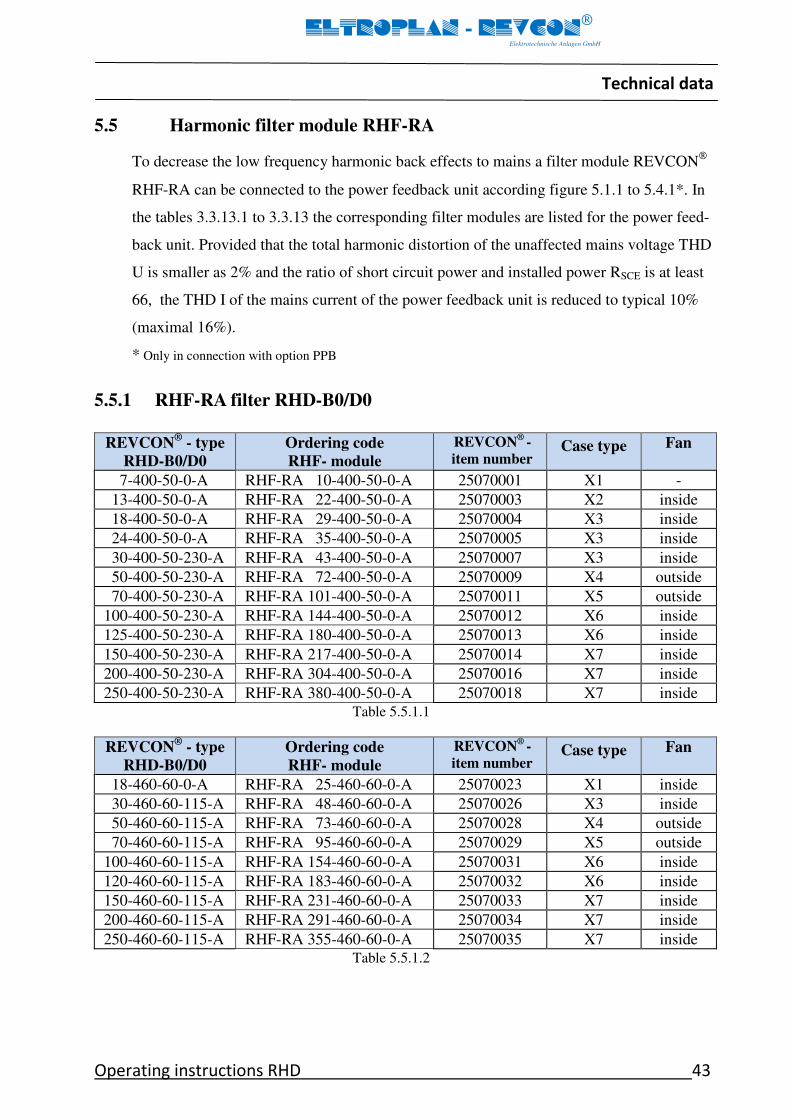
Technical data
Operating instructions RHD 43
ELTROPLAN - REVCON
Elektrotechnische Anlagen GmbH
5.5 Harmonic filter module RHF-RA
To decrease the low frequency harmonic back effects to mains a filter module REVCON
RHF-RA can be connected to the power feedback unit according figure 5.1.1 to 5.4.1*. In
the tables 3.3.13.1 to 3.3.13 the corresponding filter modules are listed for the power feed-
back unit. Provided that the total harmonic distortion of the unaffected mains voltage THD
U is smaller as 2% and the ratio of short circuit power and installed power RSCE is at least
66, the THD I of the mains current of the power feedback unit is reduced to typical 10%
(maximal 16%).
* Only in connection with option PPB
5.5.1 RHF-RA filter RHD-B0/D0
REVCON®
- type
RHD-B0/D0
Ordering code
RHF- module
REVCON®
-
item number Case type
Fan
7-400-50-0-A RHF-RA 10-400-50-0-A 25070001 X1 -
13-400-50-0-A RHF-RA 22-400-50-0-A 25070003 X2 inside
18-400-50-0-A RHF-RA 29-400-50-0-A 25070004 X3 inside
24-400-50-0-A RHF-RA 35-400-50-0-A 25070005 X3 inside
30-400-50-230-A RHF-RA 43-400-50-0-A 25070007 X3 inside
50-400-50-230-A RHF-RA 72-400-50-0-A 25070009 X4 outside
70-400-50-230-A RHF-RA 101-400-50-0-A 25070011 X5 outside
100-400-50-230-A RHF-RA 144-400-50-0-A 25070012 X6 inside
125-400-50-230-A RHF-RA 180-400-50-0-A 25070013 X6 inside
150-400-50-230-A RHF-RA 217-400-50-0-A 25070014 X7 inside
200-400-50-230-A RHF-RA 304-400-50-0-A 25070016 X7 inside
250-400-50-230-A RHF-RA 380-400-50-0-A 25070018 X7 inside
Table 5.5.1.1
REVCON®
- type
RHD-B0/D0
Ordering code
RHF- module
REVCON®
-
item number Case type
Fan
18-460-60-0-A RHF-RA 25-460-60-0-A 25070023 X1 inside
30-460-60-115-A RHF-RA 48-460-60-0-A 25070026 X3 inside
50-460-60-115-A RHF-RA 73-460-60-0-A 25070028 X4 outside
70-460-60-115-A RHF-RA 95-460-60-0-A 25070029 X5 outside
100-460-60-115-A RHF-RA 154-460-60-0-A 25070031 X6 inside
120-460-60-115-A RHF-RA 183-460-60-0-A 25070032 X6 inside
150-460-60-115-A RHF-RA 231-460-60-0-A 25070033 X7 inside
200-460-60-115-A RHF-RA 291-460-60-0-A 25070034 X7 inside
250-460-60-115-A RHF-RA 355-460-60-0-A 25070035 X7 inside
Table 5.5.1.2

Technical data
44 Operating instructions RHD
ELTROPLAN - REVCON
Elektrotechnische Anlagen GmbH
REVCON®
- type
RHD-B0/D0
Ordering code
RHF- module
REVCON®
-
item number Case type
Fan
18-500-50-0-A RHF-RA 24-500-50-0-A 25070082 X4 outside
30-500-50-230-A RHF-RA 36-500-50-0-A 25070084 X4 outside
50-500-50-230-A RHF-RA 58-500-50-0-A 25070086 X5 outside
70-500-50-230-A RHF-RA 87-500-50-0-A 25070088 X6 outside
100-500-50-230-A RHF-RA 128-500-50-0-A 25070090 X6 outside
120-500-50-230-A RHF-RA 155-500-50-0-A 25070091 X7 outside
150-500-50-230-A RHF-RA 197-500-50-0-A 25070092 X7 outside
200-500-50-230-A RHF-RA 240-500-50-0-A 25070093 X7 outside
Table 5.5.1.3
REVCON®
- type
RHD-B0/D0
Ordering code
RHF- module
REVCON®
-
item number Case type
Fan
12-690-50-230-A RHF-RA 15-690-50-0-A 25070060 X3 inside
24-690-50-230-A RHF-RA 20-690-50-0-A 25070061 X3 inside
35-690-50-230-A RHF-RA 36-690-50-0-A 25070064 X4 outside
50-690-50-230-A RHF-RA 50-690-50-0-A 25070065 X5 outside
70-690-50-230-A RHF-RA 58-690-50-0-A 25070066 X5 outside
110-690-50-230-A RHF-RA 87-690-50-0-A 25070068 X6 outside
150-690-50-230-A RHF-RA 128-690-50-0-A 25070070 X6 outside
200-690-50-230-A RHF-RA 197-690-50-0-A 25070072 X7 outside
250-690-50-230-A RHF-RA 240-690-50-0-A 25070073 X7 outside
Table 5.5.1.4

Installation
Operating instructions RHD 45
ELTROPLAN - REVCON
Elektrotechnische Anlagen GmbH
6 Installation
Mechanical installation
Important hints
• Use the power feedback units as build-in devices only!
• Observe free spaces!
- Several power feedback units in one cabinet may be installed next to
each other without spacing.
- Keep a horizontal distance of at least 70mm to other components and to the cabi-
net walls.
- Keep a vertical distance of at least 150mm to other components and to the cabinet
walls.
• Ensure that there are no obstacles in the way of the cooling air input and output.
• If the cooling air is polluted (dust, dirt swirl, grease, aggressive gas ) so that the func-
tion of the power feedback unit may be impeded
- Take sufficient countermeasures, e.g. separate cooling air, mounting of air fil-
ters, periodical cleaning.
• Do not exceed the ambient temperature permissible during operation.
Provided mounting position
The power feedback unit has been designed for vertical wall mounting (± 15°) only.
Mounting is allowed only on a flat surface without using any kind of spacers. This kind of
mounting is necessary to guarantee the right way for the cooling air. A power loss of 3 %
from the maximum nominal power rating has to be calculated. Air-temperature may not
exceed 40 °C near the unit. Air-in- and air-out-openings at the top and the bottom of the
unit may not be concealed by installation materials such as cable ducts or other equipment.
Keep a distance of min. 15 cm to the air-in- and air-out-openings and a distance of min. 7
cm to beside mounted parts or cabinet-walls.

Installation
46 Operating instructions RHD
ELTROPLAN - REVCON
Elektrotechnische Anlagen GmbH
6.1 Dimensions REVCON RHD
Dimension diagrams:
REVCON®
- Type Enclosure 0/340
RHD B0 7-400-... und RHD D0 7-400-...
REVCON®
- Type Enclosure 1/500
RHD B0 4-230-... to RHD B0 17-230-... RHD B0 13-400-... to RHD B0 30-400-...
RHD B0 18-460-... to RHD B0 30-460-... RHD B0 18-500-... to RHD B0 30-500-...
RHD B0 12-690-... to RHD B0 24-690-... RHD D0 4-230-... to RHD D0 17-230-...
RHD D0 13-400-... to RHD D0 30-400-... RHD D0 18-460-... to RHD D0 30-460-...
RHD D0 18-500-... to RHD D0 30-500-...
RHD B1 7-400-... to RHD B1 22-400-...
RHD D1 7-400-... to RHD D1 22-400-...
REVCON®
- Type Enclosure 2/700
RHD B0 25-230-... to RHD B0 40-230-... RHD B0 50-400-... to RHD B0 70-400-...
RHD B0 50-460-... to RHD B0 70-460-... RHD B0 70-690-...
RHD D0 25-230-... to RHD D0 40-230-... RHD D0 50-400-... to RHD D0 70-400-...
RHD D0 50-460-... to RHD D0 70-460-... RHD D0 50-500-... to RHD D0 70-500-...
RHD B0/D0 35-690-... to RHD B0/D0 70-690-...
RHD B1 30-400-... and RHD D1 30-400-…
REVCON®
- Type Enclosure 3/800
RHD B0 55-230-... to RHD B0 115-230-... RHD B0 100-400-... to RHD B0 250-400-...
RHD B0 100-460-... to RHD B0 150-460-... RHD B0 100-500-... to RHD B0 150-500-...
RHD D0 55-230-... to RHD D0 70-230-... RHD D0 100-400-... to RHD D0 125-400-...
RHD D0 100-460-... to RHD D0 120-460-... RHD D0 100-500-... to RHD D0 120-500-...
REVCON®
- Type Enclosure 3/801
RHD B0 200-460-... and RHD B0 250-460-... RHD B0 200-500-...
RHD B0 110-690-... to RHD B0 250-690-... RHD D0 85-230-... to RHD B0 115-230-...
RHD B0 150-400-... to RHD B0 250-400-... RHD D0 150-460-... to RHD D0 250-460-...
RHD D0 165-500-... to RHD D0 218-500-... RHD D0 150-690-... to RHD D0 250-690-...

Installation
Operating instructions RHD 47
ELTROPLAN - REVCON
Elektrotechnische Anlagen GmbH
1. Enclosure 0/340
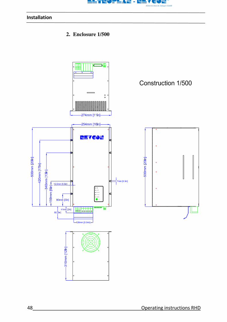
Installation
48 Operating instructions RHD
ELTROPLAN - REVCON
Elektrotechnische Anlagen GmbH
2. Enclosure 1/500

Installation
Operating instructions RHD 49
ELTROPLAN - REVCON
Elektrotechnische Anlagen GmbH
3. Enclosure 2/700

Installation
50 Operating instructions RHD
ELTROPLAN - REVCON
Elektrotechnische Anlagen GmbH
4. Enclosure 3/800

Installation
Operating instructions RHD 51
ELTROPLAN - REVCON
Elektrotechnische Anlagen GmbH
5. Enclosure 3/801
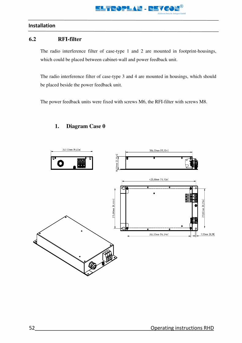
Installation
52 Operating instructions RHD
ELTROPLAN - REVCON
Elektrotechnische Anlagen GmbH
6.2 RFI-filter
The radio interference filter of case-type 1 and 2 are mounted in footprint-housings,
which could be placed between cabinet-wall and power feedback unit.
The radio interference filter of case-type 3 and 4 are mounted in housings, which should
be placed beside the power feedback unit.
The power feedback units were fixed with screws M6, the RFI-filter with screws M8.
1. Diagram Case 0

Installation
Operating instructions RHD 53
ELTROPLAN - REVCON
Elektrotechnische Anlagen GmbH

Installation
54 Operating instructions RHD
ELTROPLAN - REVCON
Elektrotechnische Anlagen GmbH
1. Diagram Case 1

Installation
Operating instructions RHD 55
ELTROPLAN - REVCON
Elektrotechnische Anlagen GmbH
2. Diagram Case 2
3. Diagram Case 3

Installation
56 Operating instructions RHD
ELTROPLAN - REVCON
Elektrotechnische Anlagen GmbH
4. Diagram Case 4

Installation
Operating instructions RHD 57
ELTROPLAN - REVCON
Elektrotechnische Anlagen GmbH
6.3 RHF-RA-filter
1. Diagram X1
2. Diagram X2

Installation
58 Operating instructions RHD
ELTROPLAN - REVCON
Elektrotechnische Anlagen GmbH
3. Diagram X3
4. Diagram X4
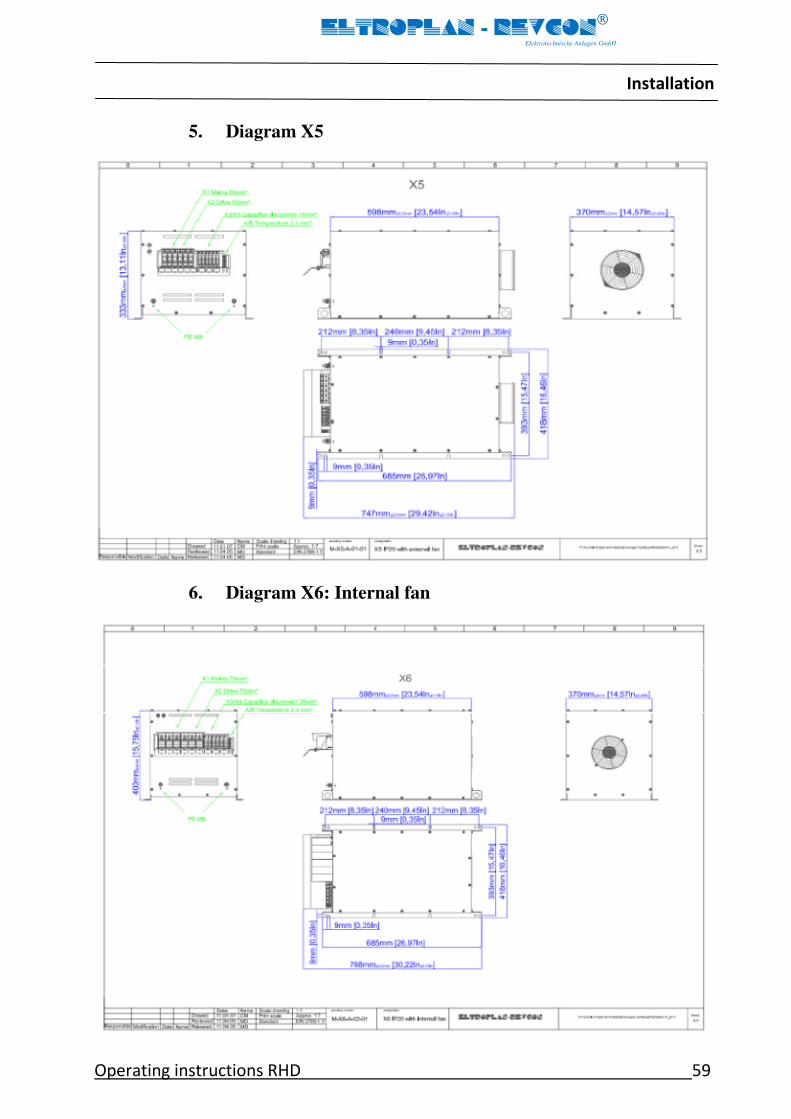
Installation
Operating instructions RHD 59
ELTROPLAN - REVCON
Elektrotechnische Anlagen GmbH
5. Diagram X5
6. Diagram X6: Internal fan

Installation
60 Operating instructions RHD
ELTROPLAN - REVCON
Elektrotechnische Anlagen GmbH
7. Diagram X7: External fan
8. Diagram X7: Internal fan

Installation
Operating instructions RHD 61
ELTROPLAN - REVCON
Elektrotechnische Anlagen GmbH
9. Diagram X7: External fan

Electrical Installation
62 Operating instructions RHD
ELTROPLAN - REVCON
Elektrotechnische Anlagen GmbH
7 Electrical Installation
Operator’s safety
Danger!
After mains disconnection, the DC-bus terminals of the power feedback unit remain live for sev-
eral minutes! The exact time, till this voltage has decreased to a not dangerous value is depend-
ent on the used controller and has to run down before any service operations or similar activities
are started.
The exact values have to be cross checked with the documentation of the controller.
Replace defective fuses by the regular types (chapter 3.3.3.2) only and without any live
voltage.
Protection of the power feedback unit
Stop!
The power feedback units contain electrostatic sensitive devices (ESSD).
During working at the terminals the personnel has to observe the rules of the international stan-
dard IEC 747-1 chapter 9. Basically before starting the works the personnel has to free itself
from electrostatic voltages:
Discharge yourself by touching the PE-screw of the housing or another grounded surface in the
cabinet.
STOP

Electrical Installation
Operating instructions RHD 63
ELTROPLAN - REVCON
Elektrotechnische Anlagen GmbH
7.1 Mains types / Mains characteristics
Danger!
Observe the restrictions in accordance to the respective mains type!
If you want to run power feedback units at mains types, which are not listed in the table below
please consult our technicians.
VDE conformal
mains type
Operation of the
power feedback unit Remark
With grounded star point Allowed Observe the technical data of the unit
With isolated star point Allowed
The voltage between L1-L3 and PE
must not be higher than the nominal
voltage
With grounded active wire Allowed
The voltage between L1-L3 and PE
must not be higher than the nominal
voltage Table 7.1.1.1
Specifications of the used wires
• The used wires have to be compliant with the specifications on site ( e.g. UL or
UL-c)
• The regulations about the minimum cross section of PE-wires have to be observed!
• The effectiveness of a screened wire is dependent on:
- a good screen connection
- low screening impedance:
Use screens tin- or nickel-plated copper screens only!
- the swamp factor of the screen mesh:
at least 70% to 80% with a swamp angle of 90°
• Protect the mains wires of the power feedback unit with the provided wire protec-
tion fuses.
Electrical Installation
64 Operating instructions RHD
ELTROPLAN - REVCON
Elektrotechnische Anlagen GmbH
7.2 Connection
The wires will be connected to the terminals at the bottom terminal plate.
7.3 Power connection
Fusing (also refer to chapter 3.3.4)
• The specifications of chapter 3.3.4 (fuses and wire cross sections) are recommenda-
tions and refer to the operation
– in cabinets and machines
– installation in cable ducts
– maximum ambient temperature +40°C.
• When choosing the cross section of the wire the voltage drop under load should be
considered (refer to chapter 3.4)
• Protection of the wires at mains side (L1, L2, and L3):
– by commercial wire protection fuses
– fuses have to be compliant with the relevant standards on site
– rated voltage of the fuses have to be compliant with the voltage on site
• Protection of the power feedback unit at mains side (L1, L2, and L3):
– By commercial semiconductor fuses.
– Fuses have to be compliant with the relevant standards on site.
– Rated voltage of the fuses has to be compliant with the voltage on site.
• Protection of the power feedback unit at DC side (+UG, -UG):
– fuses are part of the power feedback unit (refer to chapter 3.3.4.2).
The erector/user of the plant bears the responsibility for the observance of fur-
ther relevant standards (e.g.: VDE 0113, VDE 0289 and so on).

Electrical Installation
Operating instructions RHD 65
ELTROPLAN - REVCON
Elektrotechnische Anlagen GmbH
Connection
• All connections should be as short and low-impedance as possible.
• For the observance of the EMC-guideline (in accordance to actual standards like VDE
0160 and EN 50178) screened wires have to be used.
• Connect the mains supply wires at the terminals L1, L2, L3 (at the mains choke) of the
power feedback unit. Only three phase connection is allowed.
• A defined phase sequence (clockwise rotation field) must be observed at the main cir-
cuit connection of the power unit. The power feedback unit is equipped with a phase-
sequence control unit. In case of an incorrect rotation field an error message is dis-
played via LED as follows: "rotation field failure" or "phase failure". In this case two
phases, connected to the power unit, have to be exchanged.
• Connect the earthing wire of the supply cables to the earthing screw of the power
feedback unit.
• The wires for the DC-bus coupling between controller and power feedback unit have
to be connected to the DC-terminals. It is absolutely necessary to observe the correct
polarity.
Danger!
Interchanging of + (PLUS) and – (MINUS) avoids the correct function of the power feedback
unit.
Danger!
It is in no case allowed to pre-connect uncompensated direct inductances!
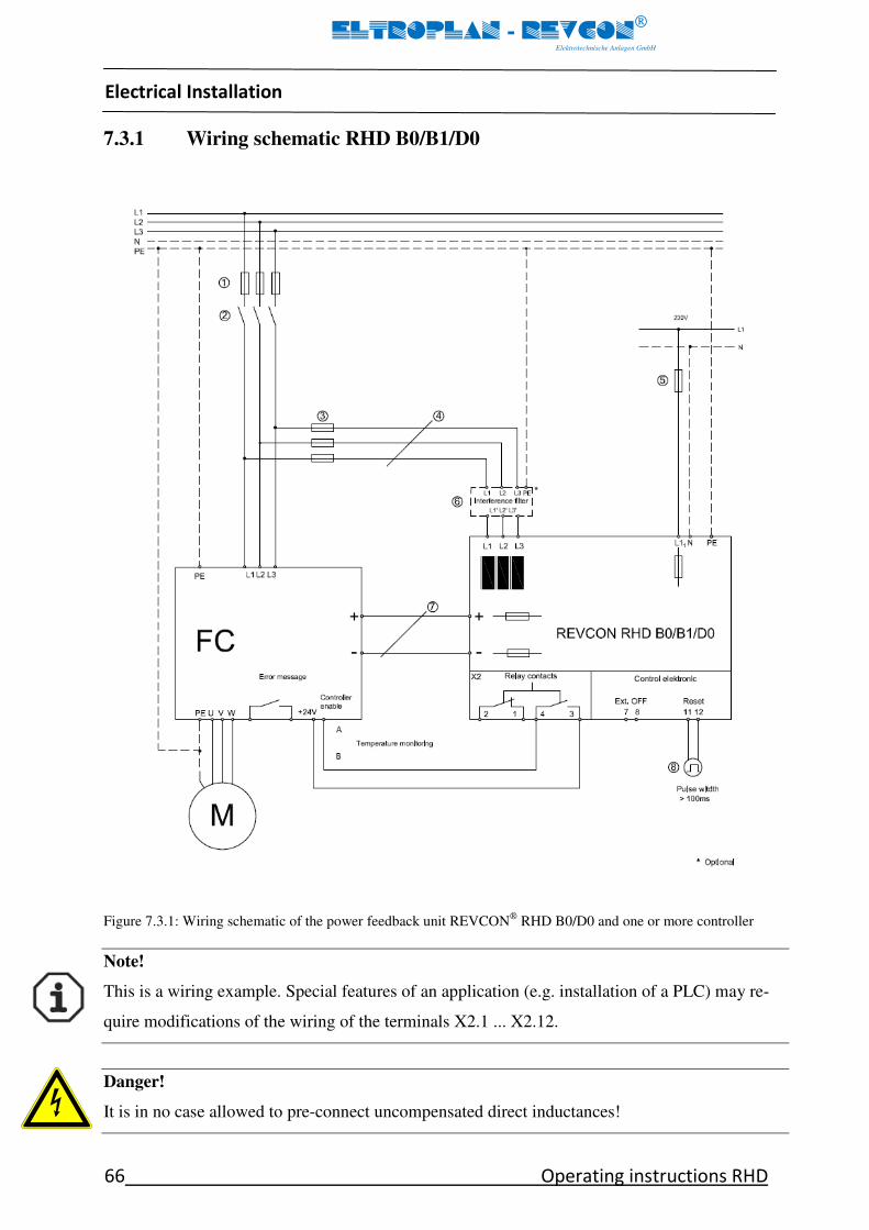
Electrical Installation
66 Operating instructions RHD
ELTROPLAN - REVCON
Elektrotechnische Anlagen GmbH
7.3.1 Wiring schematic RHD B0/B1/D0
Figure 7.3.1: Wiring schematic of the power feedback unit REVCON
RHD B0/D0 and one or more controller
Note!
This is a wiring example. Special features of an application (e.g. installation of a PLC) may re-
quire modifications of the wiring of the terminals X2.1 ... X2.12.
Danger!
It is in no case allowed to pre-connect uncompensated direct inductances!

Electrical Installation
Operating instructions RHD 67
ELTROPLAN - REVCON
Elektrotechnische Anlagen GmbH
Legend for figure 7.3.1 (REVCON RHD B0/B1/D0)
1. Fusing in accordance with controller manual.
2. It is not allowed to connect any other devices except the frequency inverter and the
power feedback unit behind the main magnetic switch.
Danger!
If this is not observed, you take the risk that, in the case of switching off the mains during feed-
back the power, the voltage in that sector may rise up to a dangerous level. This may destroy the
connected devices and perhaps also the inverter and/or the power feedback unit. To avoid such
situation, the power feedback unit is equipped with an overvoltage switch off, but nevertheless
this hint should be observed!
3. Fusing in accordance with power feedback unit manual. Fusing in accordance with
power feedback unit manual. This may be left out if at position 1 a short-circuit proof
line is used.
4. Cross section in accordance with the relevant VDE-rules.
5. Fusing (230 V supply, <2A current input) in accordance with DIN VDE 0298 or short
circuit proof wiring.
6. Interference filter, optional.
7. At these terminals one or more controllers (even with different power ratings) may be
attached, like it shown in figure 4.5.1. Even if several controllers are attached, the
wires have to be as short and low impedance as possible!
8. The „ON“ or „RESET“ signal may be initiated via terminals 11 and 12:
Terminals 11 and 12: Positive pulse (12-24 V DC); practicable e.g. via PLC
(terminal 11 +, terminal 12 -).

Electrical Installation
68 Operating instructions RHD
ELTROPLAN - REVCON
Elektrotechnische Anlagen GmbH
7.3.2 Wiring schematic RHD B0/D0 and FC with RHF-RA
Figure 7.3.2: Wiring schematic of the power feedback unit REVCON
RHD B0/D0 and one or more controller
Note!
This is a wiring example. Special features of an application (e.g. installation of a PLC) may re-
quire modifications of the wiring of the terminals X2.1 ... X2.12.
Danger!
It is in no case allowed to pre-connect uncompensated direct inductances!

Electrical Installation
Operating instructions RHD 69
ELTROPLAN - REVCON
Elektrotechnische Anlagen GmbH
Danger!
At this configuration the input current of the frequency converter must not exceed the nominal
current of the RHF-RA!
At non observance damages at the RHF-RA and / or the frequency converter cannot be ex-
cluded!
Legend for figure 7.3.2 (REVCON RHD B0/D0 and FC with RHF-RA)
1. Fusing in accordance with controller manual.
2. It is not allowed to connect any other devices except the frequency inverter and the
power feedback unit behind the main magnetic switch.
Danger!
If this is not observed, you take the risk that, in the case of switching off the mains during feed-
back the power, the voltage in that sector may rise up to a dangerous level. This may destroy
the connected devices and perhaps also the inverter and / or the power feedback unit. To avoid
such a situation, the power feedback unit is equipped with an overvoltage switch off, but never-
theless this hint should be observed!
3. RHF-RA module
4. Fusing in accordance with power feedback unit manual. This may be left out if at
position 1 a short-circuit proof line is used.
5. Cross section in accordance with the relevant VDE-rules.
6. Interference filter, optional.
7. Fusing (230 V supply, <2A current input) in accordance with DIN VDE 0298 or
short circuit proof wiring.
8. At these terminals one or more controllers (even with different power ratings) may
be attached, like it shown in figure 4.5.1. Even if several controllers are attached, the
wires have to be as short and low impedance as possible!
9. The „ON“ or „RESET“ signal may be initiated via terminals 11 and 12:
Terminals 11 and 12: Positive pulse (12-24 V DC); practicable e.g. via PLC
(terminal 11 +, terminal 12 -).
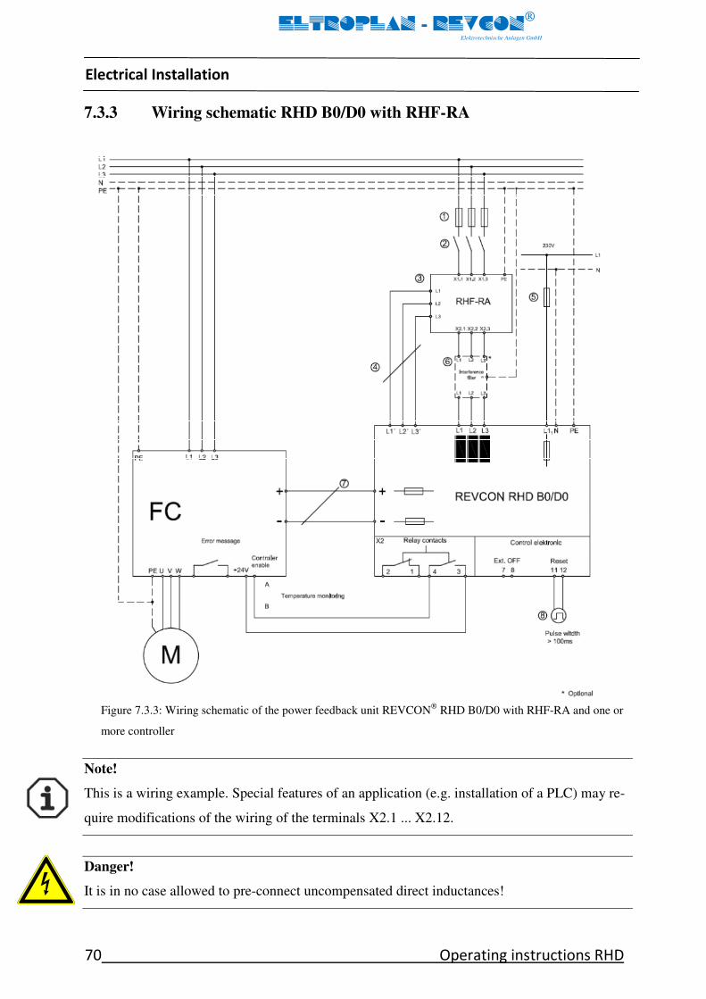
Electrical Installation
70 Operating instructions RHD
ELTROPLAN - REVCON
Elektrotechnische Anlagen GmbH
7.3.3 Wiring schematic RHD B0/D0 with RHF-RA
Figure 7.3.3: Wiring schematic of the power feedback unit REVCON
RHD B0/D0 with RHF-RA and one or
more controller
Note!
This is a wiring example. Special features of an application (e.g. installation of a PLC) may re-
quire modifications of the wiring of the terminals X2.1 ... X2.12.
Danger!
It is in no case allowed to pre-connect uncompensated direct inductances!

Electrical Installation
Operating instructions RHD 71
ELTROPLAN - REVCON
Elektrotechnische Anlagen GmbH
Legend for figure 7.3.3 (REVCON RHD B0/D0 with RHF-RA)
1. Fusing in accordance with controller manual.
2. It is not allowed to connect any other devices except the frequency inverter and the
power feedback unit behind the main magnetic switch.
Danger!
If this is not observed, you take the risk that, in the case of switching off the mains during feed-
back the power, the voltage in that sector may rise up to a dangerous level. This may destroy the
connected devices and perhaps also the inverter and/or the power feedback unit. To avoid such
situation, the power feedback unit is equipped with an overvoltage switch off, but nevertheless
this hint should be observed!
3. RHF-RA module
4. Cross section in accordance with the relevant VDE-rules.
5. Fusing (230 V supply, <2A current input) in accordance with DIN VDE 0298 or short
circuit proof wiring.
6. Interference filter, optional.
7. At these terminals one or more controllers (even with different power ratings) may be
attached, like it shown in figure 4.5.1. Even if several controllers are attached, the
wires have to be as short and low impedance as possible!
8. The „ON“ or „RESET“ signal may be initiated via terminals 11 and 12:
Terminals 11 and 12: Positive pulse (12-24 V DC); practicable e.g. via PLC
(terminal 11 +, terminal 12 -).
Electrical Installation
72 Operating instructions RHD
ELTROPLAN - REVCON
Elektrotechnische Anlagen GmbH
7.4 Fan supply
Some devices are equipped with two additional terminals at the connection plate of the
feedback unit for the supply of the fan. The fuse inside the fuse terminal is installed for
internal wire protection and of the following type 2A medium 500V 5x30mm.
7.5 Control wires
• Connect the control wires to the terminal row X2 at the connection plate of the power
feedback unit.
• Don’t parallel control wires to interfering power wires.
• Connect the screening of the control wires with an as big as possible surface to the
metal cable glands of the flange.
7.6 Control functions
The control terminal strip is placed on the connection plate and is indicated with X2. It is
fitted with a plug-in device for easy handling (see figure 4.4.4.2).
The control board must always be designed for the respective main circuit voltage. There-
fore the main circuit voltage (230 V, 380 V - 415 V, 440 V - 480 V, 500 V or 690 V)
must be declared with every order. This is also necessary for a possible exchange of the
device.
From the control terminal strip the operating condition or rather the collective error can
be connected to extern. There is also the possibility to execute the external reset or the
switch- functions and to connect them with the controller or the PLC.
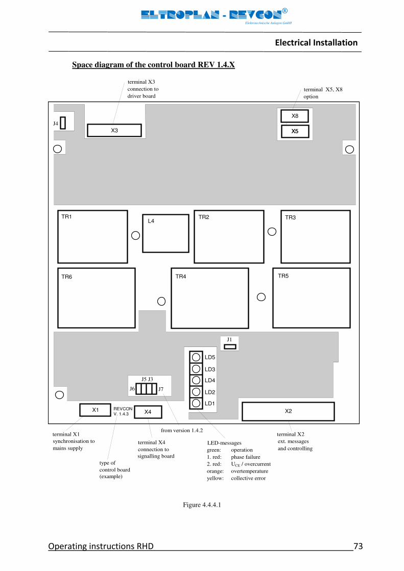
Electrical Installation
Operating instructions RHD 73
ELTROPLAN - REVCON
Elektrotechnische Anlagen GmbH
Space diagram of the control board REV 1.4.X
REVCON
V. 1.4.3 X1 X2 X4
LD1
LD3
LD4
LD5
TR1 TR2 TR3
TR6 TR4 TR5
L4
terminal X3
connection to
driver board
terminal X1
synchronisation to
mains supply
terminal X2
ext. messages
and controlling terminal X4
connection to
signalling board
type of
control board
(example)
LED-messages
green: operation
1. red: phase failure
2. red: UCE / overcurrent
orange: overtemperature
yellow: collective error
LD2
J4
X3 X5
terminal X5, X8
option
J6 J7
J5 J3
J1
X5
X8
from version 1.4.2
Figure 4.4.4.1
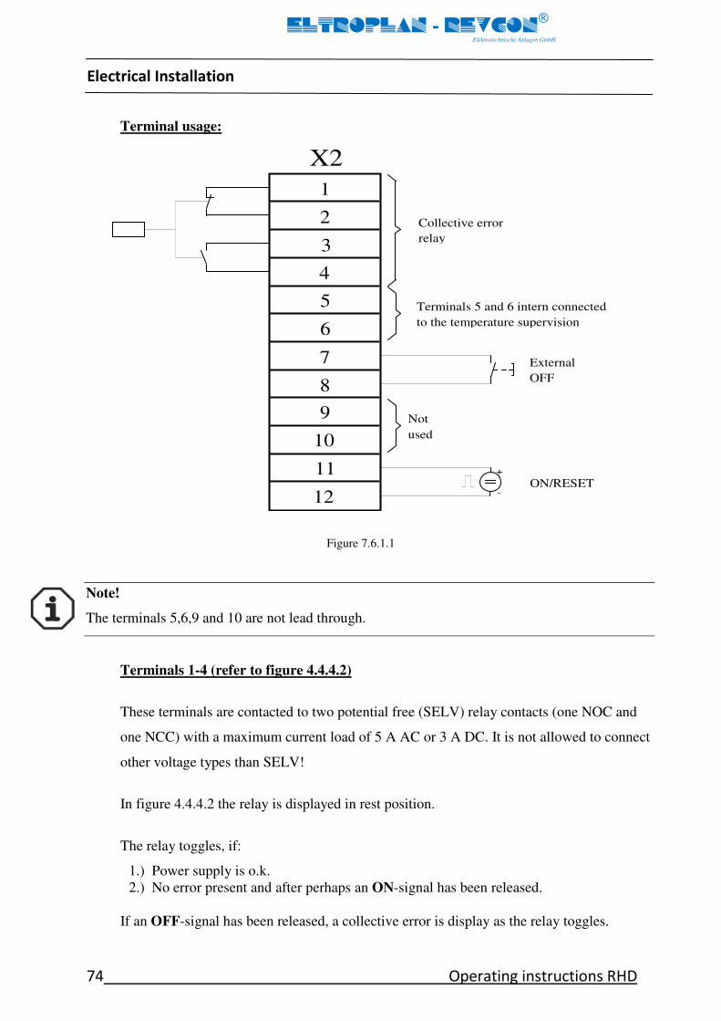
Electrical Installation
74 Operating instructions RHD
ELTROPLAN - REVCON
Elektrotechnische Anlagen GmbH
Terminal usage:
Figure 7.6.1.1
Note!
The terminals 5,6,9 and 10 are not lead through.
Terminals 1-4 (refer to figure 4.4.4.2)
These terminals are contacted to two potential free (SELV) relay contacts (one NOC and
one NCC) with a maximum current load of 5 A AC or 3 A DC. It is not allowed to connect
other voltage types than SELV!
In figure 4.4.4.2 the relay is displayed in rest position.
The relay toggles, if:
1.) Power supply is o.k.
2.) No error present and after perhaps an ON-signal has been released.
If an OFF-signal has been released, a collective error is display as the relay toggles.
1
2
3
4
5
6
7
8
9
10
11
12
+
-
External
OFF
Not
used
ON/RESET
Terminals 5 and 6 intern connected
to the temperature supervision
X2
Collective error
relay

Electrical Installation
Operating instructions RHD 75
ELTROPLAN - REVCON
Elektrotechnische Anlagen GmbH
Terminals 5 and 6
These terminals are already used for the internal temperature supervision of the heat sink.
Terminals 7 and 8
(Use screened wires only, max length)
OFF-signal
These terminals may be used for an external OFF-signal (NOC, short time contact) to stop
the power feedback unit.
Note!
An OFF-signal at the device stops the feedback operation immediately and leads at breaking op-
eration of the frequency converter normally to a failure of the frequency converter because of too
high DC-bus voltage link voltage.
Terminals 9 and 10
Not used.
Danger!
If an external voltage is connected to terminals 5 to 10 unattended actions and damages may oc-
cur.
Terminal 11 and 12
(Used screened wires only)
These terminals may be used for an external ON-signal (external voltage 12 – 24V DC
[e.g. from PLC], short time pulse) to start / reset the power feedback unit.
(Connect „Plus“ to terminal 11, „Minus“ to terminal 12)

Electrical Installation
76 Operating instructions RHD
ELTROPLAN - REVCON
Elektrotechnische Anlagen GmbH
7.7 Application example
Figure 7.7.1
Within greater plants several power feedback units may be coupled. Figure 6.1.1 shows an
example of a crane system with some possible combinations.
The operation of several inverters at one common DC-bus allows reducing the amount of
power feedback units. On the other hand several power feedback units may be coupled to
transmit more power. It's also possible to drive several motors at one inverter, as they react,
seen from the DC-bus (and that's, what the power feedback unit sees), like one big motor.
To proportion such a plant it is important to look at the worst case. The maximum feed-
back power of the power feedback unit has to be higher as or, at a minimum, equal to the
total amount of the braking power of the connected motors.
FC FC FC FC

Electrical Installation
Operating instructions RHD 77
ELTROPLAN - REVCON
Elektrotechnische Anlagen GmbH
7.8 Installation of a power feedback unit in a CE-typical drive system
General • The user is responsible for the compliance of his application with the EC directives.
- If you observe the following measure you can be sure that the drive system will not cause any
power-feed/feedback-unit-caused EMC problems, i.e. comply with the EMC
Directive when running the machine.
- If devices which do not comply with the CE requirement concerning noise immunity EN
61000-6-2 are operated close to the power feed/feedback unit, these devices may be interfered
electromagnetically by the power feed/feedback units.
Assembly • Connect the power feed/feedback unit and the RFI-filter to the grounded mounting plate with a
wire of large cross section as possible:
– Mounting plates with conductive surfaces (zinc-coated or stainless steel) allow permanent con-
tact.
– Varnished boards should not be used for installation in accordance with EMC.
• If you use several mounting plates:
– Connect as much surface of the mounting plates as possible (e.g. with copper bands)
• Ensure the separation of power and control cables.
• Cable guides as close as possible to the reference potential. Unguided cables have the same ef-
fect as aerials.
Filters • Use RFI filters which are assigned to the power feed/feedback unit.
RFI filters reduce impermissible high frequency interference to a permissible value.
Screening • Metallic cable glands ensure a big-surface connection between screen and housing
• If the screened wire are interrupted at relays or terminals:
- Connect the screens of the wires with a big surface to the mounting plate.
• If the mains wires between RFI-filter and power feed/feedback unit are longer than 300mm:
- Use screened mains wires
- Connect the screen direct at the controller / power feed/feedback unit and at the RFI-filter to
the mounting plate.
• Screen the control wires:
- Connect the screens on the shortest possible way to their terminals.
Earthing • All metallic conduction components (power feed/feedback unit, controller,
RFI-filter) have to be connected to one common earthing point (PE-bus bar).
• Observe the in the safety guidelines defined minimum cross sections:
- For EMC not the cross section, but the surface of a wire and the contact to the mounting plate
is important for the function.

Electrical Installation
78 Operating instructions RHD
ELTROPLAN - REVCON
Elektrotechnische Anlagen GmbH
Power feedback units are electrical units for usage in industrial and commercial plants. In
accordance with the EMC guideline 2004/108/EG it is not obligate to mark these units, as
in the sense of the EMC guideline and the EMC law they are components to be mounted
by a competent electromechanical engineer and cannot be used stand alone. The proof of
the observance of the protective aims of the EMC guideline has to be carried out by the
erector / user of the machine / plant. If the by ELTROPLAN-REVCON released RFI-
filters are used and the following measures and installation guidelines are observed, the
adherence to the prescribed data is cleared.
In combination with the related RFI-filter the power feedback unit has been designed for
the usage in ambient of the limit class „A“ („B“ on request).
Definition in accordance with basic standard:
• Electromagnetic compatibility (EMC) - Part 6-4: EN 61000-6-4 and IEC
61000-6-4:2006 Generic standards-Emission standard for industrial environments.
• Electromagnetic compatibility (EMC) - Part 6-2: EN 61000-6-2 and IEC 61000-6-2
Generic standards- Immunity for industrial environments.
Installation
Operating instructions RHD 79
ELTROPLAN - REVCON
Elektrotechnische Anlagen GmbH
8 Installation
Appropriate design of plant and cabinet:
To avoid noise in coupling lay
a) mains/supply wires
b) motor wires of controllers / servo amplifiers
c) control- and data wires (small voltage range < 48 V) with a distance of at least 15 cm
between each other.
To obtain low resistive HF-connections, grounding, screening and other metallic connec-
tions (e. g. mounting plates, mounted units) have to be done with an as big as possible
surface to metallic ground. Use grounding and potential equalisation wires with as big
cross section as possible (min. 10mm²) or thick grounding tapes.
Use copper or tinned copper screened wires only, as steel screened wires are not suitable
for high frequency applications. Connect the screen with metal clamps or metal glands to
the equalisation bars or PE-connections. Don’t longer the screen with single wires!
If external RFI-filters are use, these have to be mounted not more than 30cm away from
the noise source and with a very good, low resistive based contact.
Inductive switching units (relay, magnetic contactor and so on) have to be equipped with
varistors, RC-circuits or suppressor diodes always.
All connections have to be as short as possible and must lay as close to the ground poten-
tial as possible, as free hovering wires act like aerials.
Avoid wire loops in all wires. Connect unused wires to ground at both ends.
If unscreened wires are used, twist the pairs to attenuate unsymmetrical noise.
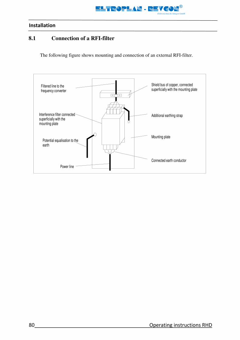
Installation
80 Operating instructions RHD
ELTROPLAN - REVCON
Elektrotechnische Anlagen GmbH
8.1 Connection of a RFI-filter
The following figure shows mounting and connection of an external RFI-filter.
Connected earth conductor
Shield bus of copper, connected superficially with the mounting plate
Mounting plate
Additional earthing strap
Power line
Interference filter connected
superficially with the mounting plate
Potential equalisation to the
earth
Filtered line to the frequency converter

Installation
Operating instructions RHD 81
ELTROPLAN - REVCON
Elektrotechnische Anlagen GmbH
8.2 Design of an EMC-conformal cabinet
1
2
12 15
7
7
9 10
6 16
4 4
13 9
14 14
8
5
3
17
6
11
1. Cabinet 8. DC-bus wiring
2. Wiring between RFI-filter with power feedback unit (DC)
and controller 9. Mounting plate (common star point)
3. RFI-filter 10. Potential equalisation
4. Mains supply wire 11. Additional earthing wire
5. Wiring between RFI-filter 12. Power feedback unit
and power feedback unit: 13. Mains connection
Cross section in accordance with fusing 14. PLC
or short circuit proof! 15. Controller
6. Motor wiring 16. Mains fuses
7. Control wiring 17. Mains magnetic switch

Installation
82 Operating instructions RHD
ELTROPLAN - REVCON
Elektrotechnische Anlagen GmbH
8.3 Remarks
Generally a system should be divided in an area for power electronics and an area for con-
trol electronics. This is not only important, if the system is mounted in one cabinet, but
even also if it is spread over several cabinets. As of the strong noise emission of the power
wires it is recommended to mount a screening wall. This wall must have a low resistive
contact to the frame or the mounting plate (remove lacquer!).
The installed power feedback unit and the connected RFI-filter must form an integrated
whole, i.e. they have to be connected via the mounting plate without an isolating lacquer.
The connection wire between power feedback unit and RFI-filter must be screened. At
both ends the screen has to be connected to ground. The wire should not be longer than
300mm.
The mounting plate of the power feedback unit should be the star point for the whole
grounding and screening of the machine or plant. If the drive or other components of the
plant cause interference, the HF connection of these components is bad. This could be im-
proved by an additional potential equalisation.
By using RFI-filters the leakage current is increased. As the leakage current is higher than
3,5 mA, one of the following conditions must be fulfilled:
- Cross section of the protective wire must be at least 10 mm² CU.
- Supervision of the protective wire by a module, which trips in case of a fault.
- Install a second wire in parallel to the protective wire via separate terminals. This wire
must be conformal with VDE 0100 / part 540.

Installation
Operating instructions RHD 83
ELTROPLAN - REVCON
Elektrotechnische Anlagen GmbH
8.4 Installation of control wires
The screen of digital signal wires, which are not connected to terminals, has to be con-
nected to the screen bars to decrease the impedance of the screen.
The screen of digital signal wires, which are connected to terminals, has to be connected
with as big surface as possible to ground.
If the screen is grounded via a single wire, the noise discharge is getting worse by 70%.
For screen connection commercial cable clamps are suitable.
If unscreened signal wires are used, install only twisted pair wires.

Commissioning
84 Operating instructions RHD
ELTROPLAN - REVCON
Elektrotechnische Anlagen GmbH
9 Commissioning
Danger!
Prior to initial switch-on of the power feedback unit check the wiring for completeness, short-
circuit and earth fault.
Danger!
If the wiring is not correct, a non-intended operation of controller and/or power feedback unit is
possible.
9.1 First powering up
1. Switch on mains supply :
- The power feedback unit is ready for operation after ca. 1s
2. Check the readiness for service of the power feedback unit:
– If only the green LED is on:
Power feedback unit is ready for service.
– If beside the green LED also other LED’s are on:
A disturbance is present. Before proceeding with commissioning, remove the
disturbance (refer to chapter 7 "Troubleshooting”).
3. Check the readiness for service of the controller:
– Proceed in accordance with the controller manual.

Configuration
Operating instructions RHD 85
ELTROPLAN - REVCON
Elektrotechnische Anlagen GmbH
10 Configuration
The coding of the jumpers enables different driving possibilities and different internal
functions in accordance to specific error messages.
In the following different definitions are explained which result from the specific possibili-
ties of coding!
a) „Autostart“
Autostart means that the device is starting with a delay-time of about 1 sec. after connect-
ing mains voltage automatically ("automatically switch-on").
Coding via jumper, see figure 4.4.4.1:
J1 closed : Autostart
If the unit should not start automatically despite the phase failure control is disabled, dur-
ing the switch on process the terminals 7 and 8 have to be bridged till 4 s after switching
on. To start the feedback afterwards a short impulse has to be given on the RESET input.
b) „Switch on“ - „Switch off“
„Switch off“ means that the driving of the semiconductors and the power feedback will be
interrupted. A braking operation of the frequency inverter with power feedback is no
longer possible.
„Switch-on“ is the activation of driving the semiconductors.
c) „Storage“
The unit is equipped with an error storage where special failures can be assigned to. Stored
error messages have to be confirmed by RESET or interruption of mains supply. "Storage"
always leads to a "switch-off" and to a collective-error-relay tripping.

Configuration
86 Operating instructions RHD
ELTROPLAN - REVCON
Elektrotechnische Anlagen GmbH
d) Reset
After the failure is removed, a stored error has to be reset by pushing the RESET-button
or rather by switching-off and on again the main circuit voltage (3-ph.)
Stop!
A reset in case of too high DC-bus voltage during the braking operation is not recommended. If
it is done nevertheless, the power semiconductors are exposed to increased stress, which may
lead to accelerated aging.
e) „Phase failure“
The phase-failure-supervision monitors the mains supply in all 3 phases.
In case of a breakdown of one phase the unit stays still in function, but with
reduced feedback power.
The power feedback unit reacts in different ways on phase failures. One possibility is the
"2 phase operation", the other one let the system get out of operation and the collective-
error-relay signals the failure.
Coding via jumper, see figure 4.4.4.1.1:
J3 J5 J6 J7 Phase-failure-supervision
— 0 0 — Sensitive, error storage "ON" 0 Jumper open
— — — — Insensitive, error storage "ON" — Jumper closed
0 X X — Off, but error storage "ON" X Jumper random
0 X X 0 Off, error storage "OFF"
Note!
Jumper J7 only exists from version 1.4.2 of the control board. Error storage "ON" means that
the error "phase failure" is shown via LED until you confirm. Error storage "OFF" how-ever
means that the error "phase failure" is shown via LED only as long as the failure really exists.
STOP

Configuration
Operating instructions RHD 87
ELTROPLAN - REVCON
Elektrotechnische Anlagen GmbH
Stop!
Pull off the jumper J3 is only allowed by interrupting the pulses of the frequency inverter or of
the power feedback unit in the case of switching off the mains by series interrupting devices like
contactors, main switches or any others. This is necessary to stop the power feedback to prevent
a dangerous voltage rise on devices in the sector where the power is switched-off. The Jumper J7
should only be removed in the case of Jumper J3 is removed. Otherwise when the phase-failure-
supervision is active a "phase failure" will only be shown as long as the failure does exist (no er-
ror storage).
f) Overvoltage supervision
Since the control board version 1.4.3 the device has an overvoltage supervision for the
mains which switches off the device in the case of a voltage level of approximately 1,15 x
UN and above. As an error message the error code 3 will be shown (see chapter 7.1). For
the differentiation of the error messages phase failure and overvoltage you have the possi-
bility to deactivate the phase-failure-supervision by removing the jumper J3 on the control
board. If after that a switch-off with the indication via the red and yellow LED (error code
3) happens, an overvoltage will be the reason of the switch-off then.
J3 J5 J6 J7 J8 LED Message Evaluation (overvoltage)
— X X — — Green 1.red Yellow Overvoltage a/o phase failure/commutation
error
— X X 0 — Green — Yellow Overvoltage
0 X X — — Green 1.red Yellow Overvoltage a/o phase failure/commutation
error
0 X X 0 — Green — Yellow Overvoltage
0 X X 0 — Green 1.red Yellow Constant phase failure
Remark:
0 Jumper open
— Jumper closed
X Jumper random
Standard adjustment of the device
Autostart and no switching off in case of phase failure
STOP

Troubleshooting and fault elimination
88 Operating instructions RHD
ELTROPLAN - REVCON
Elektrotechnische Anlagen GmbH
11 Troubleshooting and fault elimination
The five LEDs in the cover of the power feedback unit display the operating condition.
For easier visibility during service and first powering up similar LED's are placed on the
control board.
Stop!
If the power feedback unit trips during retardation, it must not be reset until the end of the re-
tardation and until the DC-bus voltage has fallen to normal values.
To avoid any kind of problems you can block the impulse-release of the inverter by connecting
the collective-error-relay-contact of the power-feedback-unit with the corresponding connec-
tion of the frequency inverter.
UCE-tripping:
The power feedback unit trips by the UCE-protective-circuitry, if the specific maximum
current of the device is exceeded. The principle of this protective-circuitry implies that
for a short time (less than one millisecond) the IGBT is stressed over its specification for
normal operation. For a single case this means no problem for the power feedback unit.
However, if the over current cut off arises often or even periodically, the high power
semiconductors will age very rapidly and fail premature.
The cause of periodical UCE cut offs may be over load, under voltage in the network, a
defective or oscillating controller, an oscillating reference input or a wrong design of the
plant.
STOP

Troubleshooting and fault elimination
Operating instructions RHD 89
ELTROPLAN - REVCON
Elektrotechnische Anlagen GmbH
11.1 LED-messages
LED – display
LED-display:
Error code:
Operation Phase failure UCE Over-temperature
Disturbance
Green
Red
Red
Orange
Yellow
1
X
2
X
3
X*
X*
X
4
X
X
5
X
X
6
X
X
7
X
X
X
8
X
X
X
9
X
X
X
X
10
X*
X
X
X*
X
11
12
X
X
13
X
X
Table 11.1.1

Troubleshooting and fault elimination
90 Operating instructions RHD
ELTROPLAN - REVCON
Elektrotechnische Anlagen GmbH
Status report Relay status
LED-display
Error code:
At commissioning
During operation
1
Ready to operate
(after approx. 1s)
System in operation Relay in
resting
position
2
Ready for operation, but no power feedback
⇒ Check the DC-fuses.
Relay in
resting
position
3
Over-temperature of the heat sink
⇒ Error-message is not resettable
as long as the temperature is too
high.
Relay
dropout
4
Error code 3
⇒ Heat sink temperature declined
to normal and the error is rese-
table.
Relay
dropout
5
System has been
switched off, (external
OFF)
⇒ Reset necessary
System has been switched off,
(external OFF)
⇒ Reset necessary
Relay
dropout
6 Overvoltage has been detected (J8 closed) ⇒ After grid volt-
age has declined to its nominal value, reset necessary
Relay
dropout
7
Rotary field orientation
incorrect or one phase is
missing
Phase failure has been detected
⇒ Reset necessary Relay
dropout
8
Overcurrent has been detected
⇒ Reset necessary
Relay
dropout
9
Error code 7 and 8 Overcurrent and phase failure have
been detected simultaneously.
Relay
dropout
10
Several errors have been
detected simultaneously
Several errors have been detected
simultaneously Relay
dropout
11 System off, at least two
phases lost
System off, at least two phases
lost. Relay
dropout
12
With option IFP: I²t-tripping
⇒ Reset necessary Relay
dropout
13
Voltage breakdown during com-
mutation but without tripping as
jumper 3 and 7 are open (chapter
6e)
⇒ Operation possible, mains sup-
ply improvement recommended
Relay
dropout
Table 11.1.2

Service
Operating instructions RHD 91
ELTROPLAN - REVCON
Elektrotechnische Anlagen GmbH
12 Service
The power feedback unit is maintenance-free, if the provided application conditions are
observed (refer to chapter 3.2).
If the cooling air is polluted, the cooling air input may be blocked. Therefore check the
power feedback unit periodically (depending on the degree of pollution approx. every 4
weeks).
Danger!
Don’t use sharp or tapering objects like knife or screw driver to clean the cooling air input.
Clean the cooling air input with a vacuum cleaner.

Appendix
92 Operating instructions RHD
ELTROPLAN - REVCON
Elektrotechnische Anlagen GmbH
13 Appendix
13.1 Options
1. Fuse holder with fuses for mains supply
In accordance with table 3.3.3.1.1-5 for the power feedback unit the following fuses are
available
REVCON®
- type Order designation Case type
RHD 7 to RHD 110 SH RHD ZZZ-XXX A
RHD 125 to RHD 250 SH RHD ZZZ-XXX B
ZZZ ≅ rated power of the power feedback unit
XXX ≅ rated voltage of the power feedback unit
2. Option IL (Isolating lacquer)
To protect the electronic components of the power feedback unit from pollution of the
cooling air, all printed circuit boards may be coated with an isolating lacquer. This option
improves the service reliability, but it doesn’t release the user from the duty to observe
the in chapter 3.2 specified application conditions.
3. Overvoltage-suppressor
If the power feedback unit (as well as a controller) is connected to ungrounded mains
supply, it only may be run, either if it is connected via an isolating transformer or if the
plant is protected by overvoltage suppressors. But also with grounded mains supply it
may be useful to install overvoltage suppressors, if it is possible, that voltage peaks occur.
For choosing the best overvoltage suppressor for your specific application, please get in
contact with one of our technicians.
4. PLC-interface
The PLC-interface makes it possible to deliver the LED messages by opto-isolator for the
message to the SPS.
5. PPB
The option PPB is required if a RHF-R is used to prevent a device defect at phase inter-
changing.

Appendix
Operating instructions RHD 93
ELTROPLAN - REVCON
Elektrotechnische Anlagen GmbH
6. External operating an signalling panel
When mounting the device inside a cabinet it is possible to mount an operator panel in
the door of the cabinet by using the external operating and signalling panel. The external
operating and signalling panel contains the complete display (LEDs) of all running and
failure messages of the power feedback unit and also the ON / RESET push button
switch.
The connection to the power feedback unit has to be done with a (shielded) flat cable to
the socket X4 of the control board (refer to figure 4.4.4.1).
Note!
The connection of the external operating and signalling panel to the power feedback unit has no
influence on the operating and error messages of the LED’s placed on the control board. In this
case both displays are active on the same time.
In case of simultaneous usage of the external operating and signalling panel and the ON/OFF
function via the control terminal X2 the switch off signal always has priority, independent of
the ON-RESTE push button switch.
Stop!
Don’t put an external voltage to the socket X4 of the control board or to the external operating
and signalling panel. This may damage the device.
STOP

Appendix
94 Operating instructions RHD
ELTROPLAN - REVCON
Elektrotechnische Anlagen GmbH
14 REVCON® Product overview
1. REVCON®
RLD
Power feedback units for short time operation
(Crane systems, discontinuous centrifugal, etc.)
2. REVCON®
RFE
Power supply- and feedback unit
(For multiple motor applications with dynamic alternation of loads)
3. REVCON®
RSU
Step- up converter for the generation of an increased direct current link voltage for the
torque increasing in over- synchronous range of speeds
4. REVCON®
RSD
Step- down converter for the generation of a decreased output voltage from a higher DC
voltage (AC output is also possible).
- Voltage controlled: A free selectable output voltage in wide limits
The required output voltage can be adjusted by set-point (0 ... 10V)
- Current controlled: A lower output voltage that adjusts free in dependence of the load
The required output current can be adjusted by set-point (0 ... 10V)
5. REVCON®
EDC
Power supply module for multiple motor applications (supply of multiple drive control-
ler) without generator- operation
6. REVCON®
RHF
Filter module for the generation of sinusoidal line currents (THD I 5-16% according to
the frequency converter and the load). Filter module of the newest generation with
smaller dimensions and reduced weight and better performance
All products are available for 400V line voltage, the most also for 230V, 400V, 460V,
500V, 600V and 690V! According to the product power from 4 to 440kW can be trans-
mitted, whereby the most products are appropriate for parallel connection, so that power
ratings until the megawatt range can be achieved!

Contact
Operating instructions RHD 95
ELTROPLAN - REVCON
Elektrotechnische Anlagen GmbH
15 Contact
Eltroplan-REVCON Elektrotechnische Anlagen GmbH
Edisonstraße 3
D-59199 Bönen
Phone +49 (0)2383 920 22 22
Fax +49 (0)2383 920 22 66
E-Mail [email protected]
Web www.REVCON.de
< SUBJECT TO CHANGE WITHOUT NOTICE >
13/09
The in these operating instructions contained details and technical data must be checked by the cos-tumer before acquisition and application. The costumer can raise no claims from these documents, compared to Eltroplan- REVCON
® or Eltroplan- REVCON
®-staff, unless that these have acted inten-
tional or grossly negligent. Eltroplan- REVCON® reserves the right to perform, without previous an-
nouncements within the appropriate and reasonable changes at their products - also at already com-missioned. All rights reserved.
Index
96 Operating instructions RHD
ELTROPLAN - REVCON
Elektrotechnische Anlagen GmbH
C
cable glands ................................................... 77
CE-marking ...................................................... 7
commutation choke ...................................... 22
compensation plants ............................... 12, 27
connection ............................................... 64, 65
contact ........................................................... 95
control functions ........................................... 72
controller ................................................... 3, 12
cooling air ...................................................... 45
current load ................................................... 74
D
dimensions .................................................... 46
drive system ........................................ 3, 11, 15 CE-typical ................................................................. 77
drive systems ................................................... 6
E
EC-Directives.................................................... 6
Efficiency ................................................. 30, 31
ESDS ............................................................... 62
F
fan supply ...................................................... 72
filtering .......................................................... 77
free spaces ..................................................... 45
G
generator ................................................. 12, 20
I
isolating lacquer ............................................ 92
L
low-voltage directive ........................... 7, 10, 29
M
Mains frequency ...................................... 30, 31
mains terminals ............................................. 35
mains types ................................................... 63
mounting position ......................................... 45
O
operating and signalling board, external ...... 93
operator’s safety ..................................... 16, 62
ordering code .................................................. 4
overvoltage suppressor ................................ 92
P
patents rights .................................................. 6
personnel qualified .................................................................... 10
pictograms .................................................... 16
power feedback unit ....................................... 3
product overview .......................................... 94
product selection ............................................ 5
protection of the device ............................... 16
R
rated data ............................................... 30, 31
readiness for service ..................................... 84
RFI-filter ........................................................ 52
S
safety information .................................. 10, 11
screening ................................................. 72, 77
standards ........................................ 8, 9, 64, 65
T
terminal usage .............................................. 74
transport ................................................. 10, 29
transport damage ........................................... 4
troubleshooting ...................................... 84, 88
U
UL ............................................................ 63, 64
user ............................................................... 15
V
voltage, external ........................................... 93
W
Warning ........................................................ 16
warranty ................................................... 6, 12
wires screened .................................................................... 63
wiring schematic ........................................... 66