Embed Size (px)
Citation preview

1
RH-45AUTO (Superficial)
Modular Rockwell Hardness Tester
Operation Instructions
G & R Technology Inc.
2
Contents
Chapter Page
1 Technical Specifications 5
2 Check Package 6
3 Functional Description 7
4 Testing Principle and Procedure 8
5 Pre-Treatment of the Test Piece 9
6 Basic Operations 9
Powering on the Device 9
Set Up a New Test 10
Testing Procedure 11
Search & Delete Test Readings 14
Transmit Data to Printer 14
Transmit Data to Windows PC 16
Initial PC Setup 16
Transferring to PC 19
7 RH-45AUTO Set Up 23
8 Hardness Tester Maintenance 25

3
General Description
The RH-45AUTO (superficial) Modular Rockwell hardness testers are accurate
advanced instruments distinguished by their friendly operation, high accuracy,
repeatability, reliability, and versatility. They are used for testing the hardnesses of a
variety of metals in different locations. They are automatic test machines built with
precise force sensors, force monitoring electronics systems, and depth measurement
systems. The RH-45AUTO are made up of a main unit and a set of frames. Each frame is
specialized for holding a certain test specimen shape or size. By switching frames on the
main unit, you can easily form specialized testers.
The RH-45AUTO can directly measure and produce 15N, 30N, 45N, 15T, 30T,
and 45T readings, and can convert to HV and HB scales. The hardness tester has
Bluetooth and USB capabilities for sending test results to a Bluetooth printer or PC.
CAUTION 1. The RH-45AUTO are automated testers. Do not touch any movable parts of the tester,
such as the indenter, when the tester is operating or injury may occur.
2. Before beginning a test, ensure the indenter is placed in the position sleeve. Otherwise
the displacement sensor will be damaged. The tester has a safety feature to detect if the
indenter is missing. If so, the presshead will automatically move backwards, and “No
Indenter” will FLASH on the display.
3. The presshead and indenter cannot move forward more than 25mm. Any attempt to
advance the presshead forward more than 25mm or retract the pressback backward before
the starting position will turn off the motor. Use a smaller retaining frame or reposition
the tester on the column stand if the test specimen is too small.
NO
INDENTER

4
Safety and Liability
This instruction manual contains important information on safety, use and maintenance of
the RH-45AUTO. Read through these instructions carefully before the first use of this
tester. Keep these instructions in a safe place for future reference.
" General warranty terms and conditions of sale and delivery " Warranty and liability
claims arising from personal injury and damage to property cannot be upheld if they are
due to one or more of the following causes:
· Failure to use the tester in accordance with its designed use as described in this
instruction.
· Incorrect performance check for operation and maintenance of the tester and its
components.
·Failure to adhere to the sections of the instructions dealing with the performance check,
operation and maintenance of the tester and its components.
·Unauthorized structural modifications to the tester and its components.
·Serious damage resulting from the effects of foreign bodies, accidents, vandalism and
force majeure.
All information contained in these instructions is presented in good faith and
believed to be correct. G & R Technology makes no warranties and excludes all liability
as to the completeness and/ or accuracy of the information.
Safety instructions
The tester is not allowed to be operated by children or anyone under the influence
of alcohol, drugs or pharmaceutical preparations. Anyone who is not familiar with these
instructions must be supervised when using the tester.

5
1. Technical Specifications
Main unit specifications
RH-150AUTO RH-45AUTO
Preliminary Load Kg(N) 10 (98.07) 3 (29.42)
Total Test Force Kg(N) 60, 100, 150
(588.4, 980.7, 1471)
15, 30, 45
(147.1, 294.2, 441.3)
Test Scale A, B, C 15N, 30N, 45N
15T, 30T, 45T
Test Load Control Load Cell Based Feedback Loop System
Test Cycle Type Motorized (Auto Load, Test and Return)
Standards Compliant ASTM E18, ISO 6508, ASTM E140
Resolution 0.1 HR
Data Output Bluetooth (to Printer ), USB (to PC)
Data Memory 1000 Test Results
Battery Rechargeable Li-ion Battery
Work Time 6 hours
Charge Time 2 hours
Weight 2 Kg
Dimensions 200mm X 110mm X 46mm
Relevant Directives EC Machinery Directive (98/37/EC)
EC Electromagnetic Compatibility Directive
(89/336/EEC)
Test Specimen Ranges
On retaining frames:
Width 0-25 mm 25-50mm 50-75mm 75-100mm
Depth 50mm 50mm 50mm 50mm
Weight 0.15kg 0.2kg 0.3kg 0.4kg
On tube testing frame: On column frame:
Thickness of
Specimen Tube
Up to 20mm Width 0-250mm
Depth 130mm
Weight 17kg

6
2. Check Package
The RH-45AUTO is available in two different packages, each containing different
frames and accessories. Upon purchase, please find the correct package list below and
check if all listed accessories are included.
Package 1: Column style stand package:
RH-45AUTO measurement component
Diamond indenter
1/16" ball indenter
20-35HRC test block
59-65HRC test block
60-90 HRBW test block
Hex key
11.1V rechargeable battery
12.6V/1.2A battery charger
Column style stand
Fastening fixture
16mm Socket Wrench
60mm plane anvil
60mm V-type anvil
Bluetooth printer and 8.4V/0.8A charger (optional)
Package 2: Retaining frames package:
RH-45AUTO measurement component
Diamond indenter
1/16" ball indenter
20-35HRC test block
59-65HRC test block
60-90 HRBW test block
Hex key
11.1V rechargeable battery
12.6V/1.2A charger
0-25mm retaining frame
25-50mm retaining frame
50-75mm retaining frame
75-100mm retaining frame
Tube-testing frame
self-aligning flat anvil
self-aligning V-type anvil
30mm flat anvil
30mm V-type anvil
Plastic case
Bluetooth printer and 8.4V/0.8A charger (optional)

7
3. Functional Description
Figures 1 and 2 illustrate the RH-45AUTO hardness tester.
Fig. 1: Tester Front View
1. LCD Monitor: displays test results, operation descriptions, and prompts.
2. Keys
key: power on/off. Note: the RH-45AUTO hardness tester has a power save
function: it will automatically turn off if inactive for 5 minutes.
Function keys: SET, MODE, , : these keys are used for various operations as
indicated on the LCD monitor.
key: Bluetooth transmission - press this key to send data to the printer.
key: begins test and moves indenter forward.
key: moves indenter backward.
STOP key: stops indenter’s movement.
3. Indenter and position sleeve: the indenter penetrates into the test specimen. The
position sleeve holds the indenter and measures the penetration depth. The
position sleeve and presshead both have marked lines. You need to line them up
when inserting the position sleeve with indenter into the presshead hole. Then
rotate the sleeve to lock it in the presshead.
4. USB connector: connects tester to an USB cable.
5. Charging port: for charging the battery
6. Anvil: holds the test specimens. Different types are available.
7. Locating slot: attaches frames with socket-head screws
8. Frame: holds the anvil. Different frames are available to accommodate different
specimen sizes and shapes.
LCD Monitor
Indenter and Position Sleeve Anvil
Frame
Keys Locating Slot

8
Figure 2: Tester Side View
Available Frames:
1. Retaining frames: the main unit and the retaining frames form a portable
hardness tester. The retaining frames have different sizes: 0-25mm, 25-50mm, 50-75mm,
and 75-100mm.
2. Tube testing frame: the main unit and the tube testing frame form a portable
tube hardness tester.
3. The column frame: the main unit and the column frame form a stand hardness
tester. There are a fastening fixture and an anvil on the stand. Attach the tester onto the
fastening fixture. To change the height of the tester, unscrew the fastening fixture from
the stand, remove it from its slot, and insert it into another slot. Place the test specimen on
the anvil. Fine tune the height of the anvil by twisting it. The column stand can be placed
in a vertical position or horizontal position.
4. Testing principle and procedure Press the key to power on the tester. Then, place the test specimen between the
anvil and indenter. Then, press the key once to move the indenter towards the test
specimen. As the indenter is moving, you can press the STOP key to stop movement.
Press the key again to resume movement.
When the indenter pushes against the test specimen, the position sleeve will
clamp the test specimen. Then, the indenter's tip will penetrate into the test specimen,
creating an indentation.
The indenter will continue to move and apply a force on the test specimen. When
the force reaches the preliminary test force F0, the indenter stops moving, wait for a
specified dwell time. The tester then measures the indentation depth on the test specimen.
After waiting, the indenter will move again and further deepening the indentation.
USB Connector
Charging Port

9
When the applied force reaches the total test force F, the indenter stops moving and waits
a specified dwell time.
After waiting, the indenter moves away from the test specimen, and decreases the
force it applies on the test specimen. When the applied force decreases back to the
preliminary test force F0, the indenter stops moving and waits for a specified dwell time.
The tester then measures the larger indentation depth on the test specimen.
The tester analyzes both indentation depths to calculate the hardness of the specimen.
The LCD displays the hardness reading. Finally, you can print the readings to a Bluetooth
printer.
5. Pre-Treatment of the Test Piece
Preparation of the test piece surface prior to testing will help insure accuracy.
a. The test should be carried out on a clean surface that is free from oxide scale,
foreign matter, and especially lubricants.
b. Preparation should be carried out in such a way that minimizes alteration of the
surface hardness (for example, heat or cold-working).
c. The thickness of the test piece should be no less than 0.08 in (2mm).
d. The test piece should have a smooth even surface. The test surface should be
polished so that a metallic luster appears. Measurement errors could result from
the roughness of the test surface. The roughness (Ra) of the surface must be
limited to 1.6 µm.
6. Basic Operations
Powering on the device Press the key to power on the tester. The LCD will display the main window, which
will show the previous test reading:
MAX 62.7 MIN 62.7
AVE 62.7 HV 764.9
1 005 62.7 N45

10
Set Up a New Test
1. At the main window, press the SET key to start and set up a new test. You will now
select the operating parameters. The LCD monitor will prompt for a number of test
results in a test group:
2. Press the or keys repeatedly to change the number of test groups per reading.
Then press the SET key to input that number and select a testing scale.
3. The LCD monitor will now prompt for a test scale. Press the key repeatedly to
cycle through N45, N30, N15, T45, T30, or T15. Each scale has a unique window
shown below:
Abbreviation: ST----Steel
AVE 04
N30 30KG DIAMOND
N30
HV: ST
HB: ST
N45 45KG DIAMOND
N45
HV: ST
HB: ST
N15 15KG DIAMOND
N15
HV: ST
HB: ST
T30 30KG Ball T30
HV: ST
HB: ST
T45 45KG Ball
T45
HV: ST
HB: ST
T15 15KG Ball
T15
HV: ST
HB: ST

11
4. Each scale’s window prompts for test piece material for converting readings. Press
the MODE key repeatedly to cycle through conversion values in Vickers (HV),
Brinell (HB). The selected parameter will flash. Note: Only steel (ST) is currently
supported for conversion.
5. Press the SET key to return to the main window:
Minimum reading
Maximum reading
Results average Converted value
Current Number
Current Reading
Group Number
Testing Procedure
1. As an example, we will perform an N45 test. Ensure the diamond indenter is
placed in the tester. If not, twist the position sleeve until its notch lines up with the
notch on the cylinder:
MAX 00.0 MIN 00.0
AVE 00.0 HV 000
1 005 00.0 N45

12
Then pull out the sleeve and replace the indenter with the correct one:
Reinsert the sleeve and twist to lock the sleeve:
2. Starting in the main window, place the test specimen between the indenter and
anvil. Then, press the key to move the indenter towards the test specimen.
(While the indenter is moving, you can press the STOP key to stop the indenter,
and then press the key again to resume moving.)
3. The indenter will apply a preliminary test force on the test specimen, then stop
moving for a specified dwell time. (The LCD monitor displays a timer for elapsed
dwell time). The LCD monitor displays this screen:
4. After the dwell time elapses, the indenter automatically resumes moving and
applies more force until the force reaches the load force. Then, the indenter stops
Preload 3.0 KG
1 SEC
Dwell Time Indicator

13
moving and pauses for a specified dwell time. The LCD monitor displays this
screen:
5. After the pause, the indenter automatically moves backwards and decreases the
force it applies on the test specimen until the force decreases back to the
preliminary test force. Then the indenter stops moving and pauses for a specified
dwell time. The LCD monitor displays this screen:
6. After the pause, the indenter continues to move backwards away from the test
specimen. You may remove the specimen. The LCD monitor displays this screen:
Unload 00.0 KG
Load 45.0 KG
Unload 10.0 KG
150.0 KG
Unload 3.0 KG
1 SEC
1 SEC

14
Finally, the LCD monitor will display the test reading:
Note: Do not touch test specimen during testing, otherwise the test reading will be
affected.
Search & Delete Test Readings
1. Search through readings in current test group
From the main window, press the key to search and cycle through the test
readings in the current group. If you want delete the currently displayed reading,
press the key. The reading will be deleted from memory and you will return to
the main window. The LCD monitor now displays the previous test reading. If you
want to return to the main window without deleting anything, press the SET key.
The previous test reading will be displayed.
2. Delete current test result
From the main window, press the key to delete current test result.
Transmit Data to Printer
1. First, power on the Bluetooth printer. Press the key to start the transmit
procedure. The tester will then attempt to pair with the printer, and the LCD window will
flash “PAIR”:
MAX 62.7 MIN 62.7
AVE 62.7 HV 764.9
1 005 62.7 N45
PRINTER
PAIR
Test Reading
Converted Reading

15
2. When both the tester and printer have been paired, the LCD window will display the
current test group number. Press the or keys to cycle through and select the group
number you wish to print.
Press the key again to transfer the selected data to the printer.
If the printer successfully receives the data, it will print the readings and the tester
will return to the main window.
If the printer did not receive the data, the tester’s LCD monitor will display:
After 30 seconds, RH-45 hardness tester will return to main window. Check if the
printer is powered on or operational and try transmitting again.
PLEASE CHECK
PRINTER STATUS
PRI
GROUP 04

16
Transmit Data to Windows PC
Initial PC Setup:
Download the Windows driver from the G & R Technology website.
Download and install the program Putty from
http://www.chiark.greenend.org.uk/~sgtatham/putty/download.html
1. Insert USB cable into the tester’s USB port.
2. Repeatedly press the MODE twice until the LCD window will display “USB
TRANSFER”
3. A prompt on your Windows 7 Computer will appear, saying drivers are not
installed
4. Enter your Windows 7 control panel. Make sure you are viewing by icons, not
category. Run device manager.
17
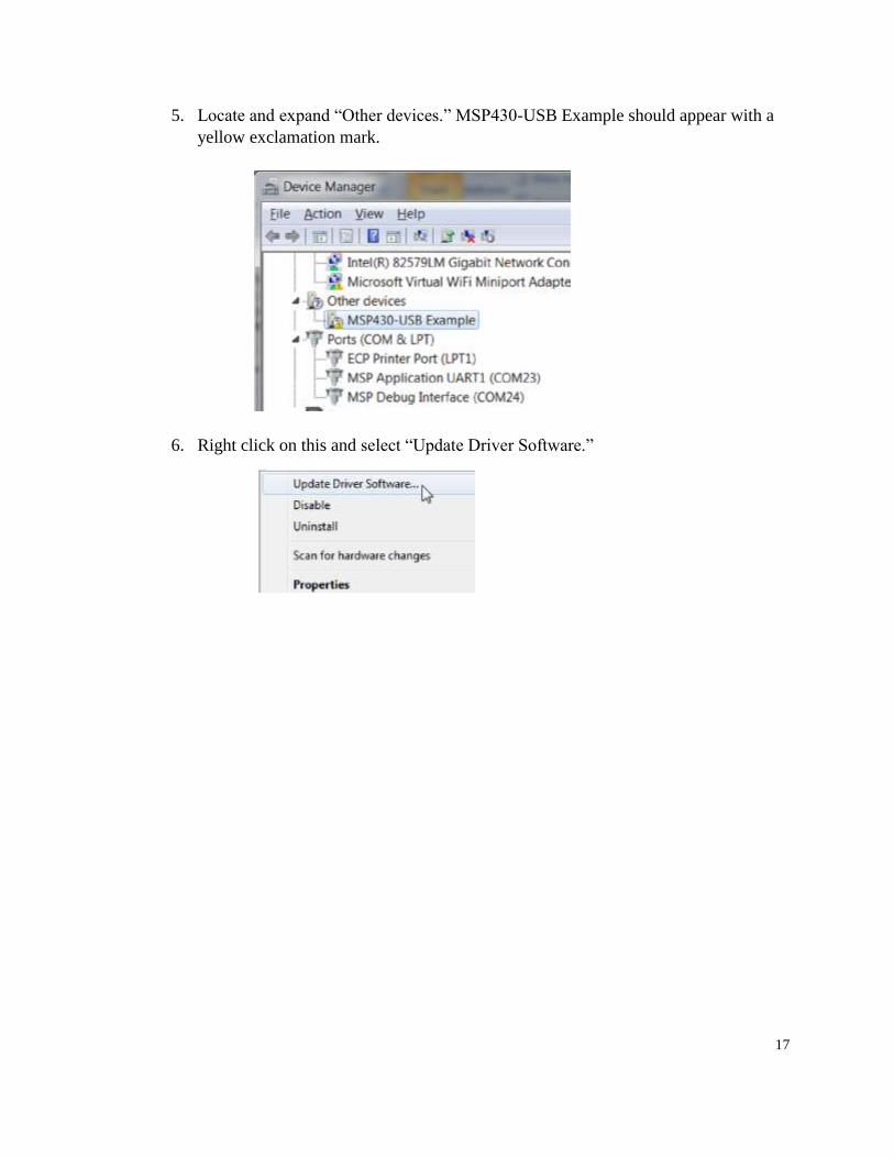
5. Locate and expand “Other devices.” MSP430-USB Example should appear with a
yellow exclamation mark.
6. Right click on this and select “Update Driver Software.”

18
7. Windows will now search for drivers for the RH-45AUTO. Press “Browse my
computer for driver software.”
8. Locate the directory which contains the driver downloaded from the G & R
Technology website.

19
9. The RH-150AUTO is now assigned a COM number. Take note of this number.
10. Unplug the USB cable and install the program Putty.
Transferring to PC:
1. Turn on the RH-45AUTO tester. Press the MODE key to select the group of
readings to transmit. The LCD window should display “USB CURRENT.”
2. Press the SET key to configure the range of test groups to transmit. The parameter
BEGIN will flash. This is the first test group of the range to transmit. Press the
Press the or keys to change the group number.
BEGIN 001
END

20
3. Press the MODE key again and the parameter END will flash. This is the last group
of the range to transmit. Press the Press the or keys to change the last group
number.
In this window, the tester will transmit groups 1, 2, 3, and 4 to the PC.
4. Press the SET key after configuring the group range and prepare to transfer. Plug in
the USB cable to the tester and PC.
5. Run the Device Manager in Windows to find the COM port of the tester. (See step 9
of the previous section “”Before you start.”)
6. Run the program Putty.
BEGIN 001
END 004

21
7. Under the “Connection type:” configuration, choose “serial” option
8. In the “Serial line” box, change the COM number to the number assigned by Device
Manager (step 5).

22
9. Click Open
10. The screen will prompt you to press any key. Press any key on your computer’s
keyboard.
11. The tester will automatically transfer one group’s readings to the Putty screen. Press
any key on the PC to transfer the next group in the range. When all groups have
transferred, you may unplug the tester from the PC.
You may select the text and copy the text to a word editor.

23
7. RH-45AUTO Setup
1. Memory Reset
NOTE: THIS PROCEDURE WILL ERASE AND RESET THE ENTIRE MEMORY! ALL
READINGS WILL BE IRRETRIEVABLE!
This function resets the whole memory. First, start with the power off.
Simultaneously hold down the and MODE keys. Then hold down the key,
and then release the and MODE keys. Finally, release the key. The LCD
monitor will display:
2. Timer setup and offset adjustment
The RH-45AUTO hardness tester has a clock for recording the test time. It also
has an offset function to increase or decrease all test readings by a certain value,
useful for matching readings to a standard test block.
To change these values, first start with the power off. Press and hold down the
SET key, and then hold down the key. Then release the SET key. Finally,
release the key. The LCD monitor will enter this screen:
MAX 00.0 MIN 00.0
AVE 00.0 HV 000
1 001 00.0 N45
DATA FMT USA
EUR

24
Press the MODE key to select USA (Month/Day/Year) or European
(Day/Month/Year) date format. The current selection will flash, then press the
SET key to confirm selection and the LCD monitor will enter the time screen:
Repeatedly press the MODE key to cycle through and select the year, month,
day, hour or minute.
The selected parameter will flash, and press the key or key to adjust that
parameter. When finished with all parameters, press the SET key to exit and the
LCD monitor will enter the offset screen:
You can offset test readings to match standard test block values. There is a
separate offset for each test scale. Repeatedly press the MODE key to cycle
through and select a test scale. The selected scale will flash, and press the key
or key to adjust the offset value. If the test reading is lower than the test block
value by a certain number, ADD that number. Otherwise, if test result is higher
than the test block value, SUBTRACT that number. Then the press SET key to
exit and the LCD monitor will enter the dwell time screen:
You can adjust the dwell time the tester waits before applying or removing
the preliminary and load force. Press the MODE key to cycle through and select
YEAR 14
MONTH 03
DAY 21
HOUR 07 AM
MINUTE 23
OFFSET
HRA +01
HRB +02
HRC -03
LOAD TIMER
PRELOAD 4
LOAD 8
UNLOAD 3
25
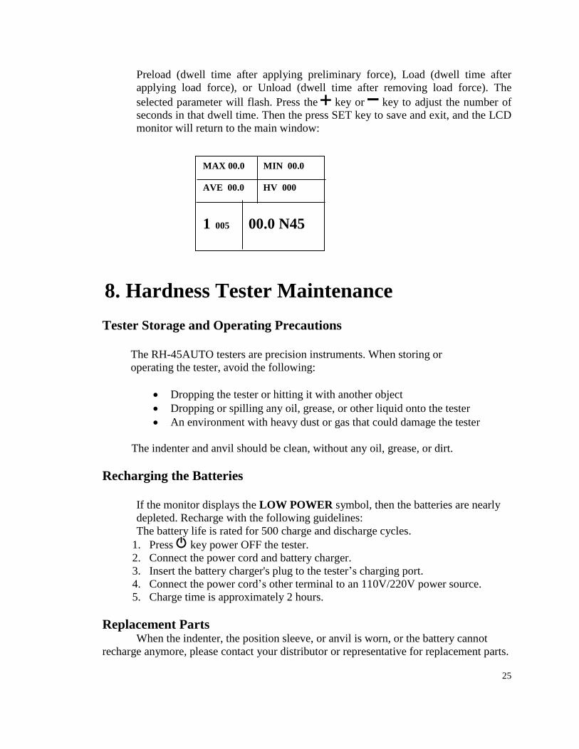
Preload (dwell time after applying preliminary force), Load (dwell time after
applying load force), or Unload (dwell time after removing load force). The
selected parameter will flash. Press the key or key to adjust the number of
seconds in that dwell time. Then the press SET key to save and exit, and the LCD
monitor will return to the main window:
8. Hardness Tester Maintenance
Tester Storage and Operating Precautions
The RH-45AUTO testers are precision instruments. When storing or
operating the tester, avoid the following:
Dropping the tester or hitting it with another object
Dropping or spilling any oil, grease, or other liquid onto the tester
An environment with heavy dust or gas that could damage the tester
The indenter and anvil should be clean, without any oil, grease, or dirt.
Recharging the Batteries
If the monitor displays the LOW POWER symbol, then the batteries are nearly
depleted. Recharge with the following guidelines:
The battery life is rated for 500 charge and discharge cycles.
1. Press key power OFF the tester.
2. Connect the power cord and battery charger.
3. Insert the battery charger's plug to the tester’s charging port.
4. Connect the power cord’s other terminal to an 110V/220V power source.
5. Charge time is approximately 2 hours.
Replacement Parts When the indenter, the position sleeve, or anvil is worn, or the battery cannot
recharge anymore, please contact your distributor or representative for replacement parts.
MAX 00.0 MIN 00.0
AVE 00.0 HV 000
1 005 00.0 N45