Embed Size (px)
Citation preview
8/2/2019 RF_TN_003 V1.0 - Wireless Network Capacity
http://slidepdf.com/reader/full/rftn003-v10-wireless-network-capacity 1/11
BeanAir1, mail Gay Lussac
Neuville-Sur-Oise, 95000, FRANCE
Doc Version : 1.1
Wireless Network Capacity Test Plan
Doc Type: Specification
Référence :P_QUAL_NWK_CAPA
Publication Date: 22/07/2010 Model : SES_V120 Page : 1 / 11
Ref : RF_TN_003 V1.0
Beanair – 1, mail Gay Lussac - 95000 Neuville-sur-Oise – France
T ECHNICAL NOTE Wireless Network capacity Test Plan
8/2/2019 RF_TN_003 V1.0 - Wireless Network Capacity
http://slidepdf.com/reader/full/rftn003-v10-wireless-network-capacity 2/11
BeanAir1, mail Gay Lussac
Neuville-Sur-Oise, 95000, FRANCE
Doc Version : 1.1
Wireless Network Capacity Test Plan
Doc Type: Specification
Référence :P_QUAL_NWK_CAPA
Publication Date: 22/07/2010 Model : SES_V120 Page : 2 / 11
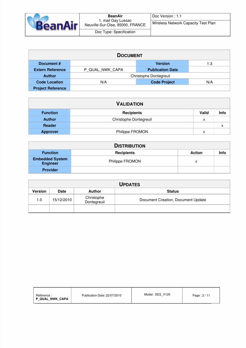
DOCUMENT Document # Version 1.3
Extern Reference P_QUAL_NWK_CAPA Publication Date
Author Christophe Dontegreuil
Code Location N/A Code Project N/A
Project Reference
VALIDATION
Function Recipients Valid InfoAuthor Christophe Dontegreuil x
Reader x
Approver Philippe FROMON x
DISTRIBUTION Function Recipients Action Info
Embedded SystemEngineer
Philippe FROMON x
Provider
UPDATES Version Date Author Status
1.0 15/12/2010ChristopheDontegreuil
Document Creation, Document Update

8/2/2019 RF_TN_003 V1.0 - Wireless Network Capacity
http://slidepdf.com/reader/full/rftn003-v10-wireless-network-capacity 3/11
BeanAir1, mail Gay Lussac
Neuville-Sur-Oise, 95000, FRANCE
Doc Version : 1.1
Wireless Network Capacity Test Plan
Doc Type: Specification
Référence :P_QUAL_NWK_CAPA
Publication Date: 22/07/2010 Model : SES_V120 Page : 3 / 11
Summary
1. AIM OF THE DOCUMENT .................................................................................................................................4
2. MODELLING.......................................................................................................................................................5
3. DEPENDENCES ................................................................................................................................................6
4. INSTALLATION ..................................................................................................................................................7
5. TESTS PROTOCOLS ........................................................................................................................................8
5.1 Test: BandWidth .........................................................................................................................................8
5.1.1 Presentation .....................................................................................................................................8
5.1.2 Results ..............................................................................................................................................9

8/2/2019 RF_TN_003 V1.0 - Wireless Network Capacity
http://slidepdf.com/reader/full/rftn003-v10-wireless-network-capacity 4/11
BeanAir1, mail Gay Lussac
Neuville-Sur-Oise, 95000, FRANCE
Doc Version : 1.1
Wireless Network Capacity Test Plan
Doc Type: Specification
Référence :P_QUAL_NWK_CAPA
Publication Date: 22/07/2010 Model : SES_V120 Page : 4 / 11
1. AIM OF THE DOCUMENT
The aim of this document is to characterize the network capacity of our Wireless Sensor Networks.
This document is not intended to study radio interferences on the 2.4 GHz Band, but it helps the end
user to determine the packet fluidity on a unique PAN (Personal Area Network) by stochastic
calculus.
Please note that these computed values will change, depending heavily on the environment.

8/2/2019 RF_TN_003 V1.0 - Wireless Network Capacity
http://slidepdf.com/reader/full/rftn003-v10-wireless-network-capacity 5/11
BeanAir1, mail Gay Lussac
Neuville-Sur-Oise, 95000, FRANCE
Doc Version : 1.1
Wireless Network Capacity Test Plan
Doc Type: Specification
Référence :P_QUAL_NWK_CAPA
Publication Date: 22/07/2010 Model : SES_V120 Page : 5 / 11
2. MODELLING
What is the wireless network capacity ?
In this document, the wireless network capacity is the amount of packets transmitted, received or
lost during a specified period.
This Network capacity can be modeled by the following parameters:
LQI
LQI is equivalent to Received Signal Strength Indication (RSSI).The LQI value is between 0 and 255.
The more LQI is close to 255, the more the received signal power is strong.
PER_A
This can be local or global.
(e.g.: 3 of 1000 Packets lost on the network/on a device, approximate)
PER_R
(e.g.: 3 of 1000 Packets lost on the network Per Hour)
MNCLP Maximum number of consecutive lost packets
(e.g.: 10 consecutive Packets were lost during this test, which corresponds in a time of 10 ms.)
Bandwidth
(e.g.: This network has a 400 Hz bandwidth.)

8/2/2019 RF_TN_003 V1.0 - Wireless Network Capacity
http://slidepdf.com/reader/full/rftn003-v10-wireless-network-capacity 6/11
BeanAir1, mail Gay Lussac
Neuville-Sur-Oise, 95000, FRANCE
Doc Version : 1.1
Wireless Network Capacity Test Plan
Doc Type: Specification
Référence :P_QUAL_NWK_CAPA
Publication Date: 22/07/2010 Model : SES_V120 Page : 6 / 11
3. DEPENDENCES
There is no standard formula to compute the LQI, which depends on chipmakers.
On our RF Transceiver, there is no direct relationship between LQI and PER. In a quiet environment,PER will decrease as LQI decreases, however, if there is any interference, the PER can decreasewithout any change of the LQI.
RSSI (Received Signal Strength Indication) readings simply measure peak amounts of radio energyon the channel over a given period.
In this document and during test procedures, we admit:One RF channel is selected
Network and PAN addresses are static.
The quality of the RSSI is good
The Wireless Network capacity depends on:
Wireless Range
Transmission Power
Obstacles (Water, Metal, …)
Amount of wireless sensor.
Sample Rate per device (0 to 5kHz)
Amount of sensor channel. (1 to 4)
Antenna (type, length, …)
Interference Source (Wi-Fi , Bluetooth….)

8/2/2019 RF_TN_003 V1.0 - Wireless Network Capacity
http://slidepdf.com/reader/full/rftn003-v10-wireless-network-capacity 7/11
BeanAir1, mail Gay Lussac
Neuville-Sur-Oise, 95000, FRANCE
Doc Version : 1.1
Wireless Network Capacity Test Plan
Doc Type: Specification
Référence :P_QUAL_NWK_CAPA
Publication Date: 22/07/2010 Model : SES_V120 Page : 7 / 11
4. INSTALLATION
The following devices and parameters are used:
Type Model Quantity Version
Protocol Stack IEEE 802.15.4 N/A N/ATopology Star, Ad-Hoc N/A N/ABeanGateway® BeanGateway® Ethernet 1 v1.3
BeanDevice® BeanDevice® AN-420 9 v1.4BeanDevice® AX-3D 3 v1.5
BeanScape® BeanScape® N/A v1.9

8/2/2019 RF_TN_003 V1.0 - Wireless Network Capacity
http://slidepdf.com/reader/full/rftn003-v10-wireless-network-capacity 8/11
BeanAir1, mail Gay Lussac
Neuville-Sur-Oise, 95000, FRANCE
Doc Version : 1.1
Wireless Network Capacity Test Plan
Doc Type: Specification
Référence :P_QUAL_NWK_CAPA
Publication Date: 22/07/2010 Model : SES_V120 Page : 8 / 11
5. TESTS PROTOCOLS
5.1 TEST: BANDWIDTH
5.1.1 Presentation
Type Value
Title Characterization of the Bandwidth.
ID BANDWIDTH
Aim Characterize bandwidth and associated parameters.
Variables Sample Rate from 0 to 5 kHz,1 BeanGateway® and 1 to 9 BeanDevice®.
Achieving Criteria Bandwidth determined.
Ways Characterize parameters,when done, use the following formula:Bandwidth = Sample Rate x ACNwith PER_R >= 1%
Conditions(Constants)
Transmission power MAX,No obstacles
No Wi-Fi Interferences0.5 m < E/R Distance < 2 m.3 activated channels per AX3D4 activated channels per AN420

8/2/2019 RF_TN_003 V1.0 - Wireless Network Capacity
http://slidepdf.com/reader/full/rftn003-v10-wireless-network-capacity 9/11
BeanAir1, mail Gay Lussac
Neuville-Sur-Oise, 95000, FRANCE
Doc Version : 1.1
Wireless Network Capacity Test Plan
Doc Type: Specification
Référence :P_QUAL_NWK_CAPA
Publication Date: 22/07/2010 Model : SES_V120 Page : 9 / 11
5.1.2 Results
SR: Sample Rate of each BeanDevice® BW: Global Network Bandwith
(In Hz)
Global Network Bandwidth computed is a particular value.
In fact, a 400 Hz Bandwidth can be obtained in different ways:
Case 1: 1 BeanDevice®, 4 channels are activated @ 100 Hz.
Case 2: 4 BeanDevice®, 1 channel is activated @ 100 Hz.
Case 3: 1 BeanDevice®, 1 channel is activated @ 400 Hz.
Case 1 and 3 have the same bandwidth.
Bandwitdh = 400 Hz = 400 measure data per second = Sample Rate
8/2/2019 RF_TN_003 V1.0 - Wireless Network Capacity
http://slidepdf.com/reader/full/rftn003-v10-wireless-network-capacity 10/11
BeanAir1, mail Gay Lussac
Neuville-Sur-Oise, 95000, FRANCE
Doc Version : 1.1
Wireless Network Capacity Test Plan
Doc Type: Specification
Référence :P_QUAL_NWK_CAPA
Publication Date: 22/07/2010 Model : SES_V120 Page : 10 / 11
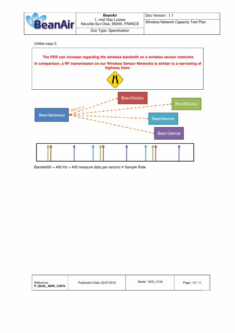
Unlike case 2,
The PER can increase regarding the wireless bandwith on a wireless sensor networks
In comparison, a RF transmission on our Wireless Sensor Networks is similar to a narrowing ofhighway lines:
.
Bandwitdh = 400 Hz = 400 measure data per second ≠ Sample Rate

8/2/2019 RF_TN_003 V1.0 - Wireless Network Capacity
http://slidepdf.com/reader/full/rftn003-v10-wireless-network-capacity 11/11
BeanAir1, mail Gay Lussac
Neuville-Sur-Oise, 95000, FRANCE
Doc Version : 1.1
Wireless Network Capacity Test Plan
Doc Type: Specification
Référence :P_QUAL_NWK_CAPA
Publication Date: 22/07/2010 Model : SES_V120 Page : 11 / 11
We might consider this formula:
In the case all BeanDevices have the same sample rate,
and are working on the same PAN in streaming mode,
the probability of a collision on a Beanair Wireless Sensor Networks
is approximately as follow:
Chan = Number of data acquisition channels
P = Probability of a collision
DTD = Data Transmission Duration ≈ 8 ms
SR = Sample Rate = 1/Period
n = Number of devices
NDPP = Number of data acquisition in a packet = 45
After several retries, if there is too many collisions, the packet is lost.
Example : Consider a wireless sensor networks with this topology:
1x BeanGateway®,
3xBeanDevice® AX3D with Sample Rate = 800 Hz, 3 activated channels
The same settings with Sample Rate = 50 Hz: