Embed Size (px)
Citation preview
RFTagAware™
Reader Configuration Guide
Version 1.3.1 Patch 2
January 2006
Copyright Copyright © 2006 ConnecTerra, Inc. All rights reserved.
Restricted Rights Legend Information in this document is furnished for informational use only, is subject to change without notice, and should not be construed as a commitment by ConnecTerra, Inc. ConnecTerra, Inc. assumes no responsibility or liability for any errors or inaccuracies that may appear in this document, nor for incidental or consequential damages resulting from the furnishing, performance, or use of this material.
This guide contains information protected by copyright. No part of this guide may be reproduced, transmitted, transcribed, stored in a retrieval system, or translated into any language in any form without prior written consent from ConnecTerra, Inc.
Trademarks or Service Marks BEA, BEA WebLogic, and ConnecTerra are registered trademarks of BEA Systems, Inc. BEA WebLogic Server, BEA WebLogic Platform, RFTagAware and Compliance Jump Start are trademarks of BEA Systems, Inc. Java is a trademark and Sun is a registered trademark of Sun Microsystems, Inc. Linux is a registered trademark of Linus Torvalds. Microsoft and Windows are trademarks of Microsoft Corporation. Oracle is a registered trademark of Oracle Corporation and/or its affiliates. Symbol is a registered trademark of Symbol Technologies, Inc. UNIX is a registered trademark of The Open Group in the United States and other countries.
All other trademarks are the property of their respective companies.
Contact Information BEA Systems, Inc. 4 Van de Graaff Drive Burlington, MA 01803 Phone: 781-993-7100 Facsimile: 781-993-7601 Web Site: www.bea.com

RFTagAware Reader Configuration Guide Page 1
RFTagAware™ Reader Configuration Guide
Contents This document describes how to configure supported RFTagAware RFID readers. Supported RFID Readers.................................................................................................................................2 Configuring Physical Readers...........................................................................................................................4
Accraply...........................................................................................................................................................5 Alien .................................................................................................................................................................7
Alien ALR-9750..........................................................................................................................................7 Alien ALR-9780..........................................................................................................................................9 Alien ALR-9800........................................................................................................................................14
Avery..............................................................................................................................................................15 Using the Easy Plug Label Scripting Language....................................................................................16
AWID ............................................................................................................................................................18 CAEN............................................................................................................................................................20 DataLogic ......................................................................................................................................................22 Escort Memory Systems (EMS) ................................................................................................................23 Identec Solutions .........................................................................................................................................25 Intermec ........................................................................................................................................................27 Paxar...............................................................................................................................................................30 Printronix ......................................................................................................................................................31
Using the Printronix Graphics Language (PGL) ................................................................................33 SAMSys..........................................................................................................................................................37
MP9320......................................................................................................................................................37 Setting the Baud Rate ..............................................................................................................................39 MP9210......................................................................................................................................................40
Symbol (Matrics) ..........................................................................................................................................43 AR400.........................................................................................................................................................43 RDR-001....................................................................................................................................................46
TAGSYS........................................................................................................................................................48 ThingMagic ...................................................................................................................................................50
Mercury3....................................................................................................................................................50 Mercury4....................................................................................................................................................52
Zebra..............................................................................................................................................................55 Using the Zebra Printing Language (ZPL II) ......................................................................................57
Appendix A: Using the ALEPC API for Stack Light Control.................................................................60 Stack Light Configuration...........................................................................................................................60 Stack Light Control .....................................................................................................................................61
Appendix B: Controlling RFID Devices Using PLCs ...............................................................................62

Page 2 RFTagAware Reader Configuration Guide
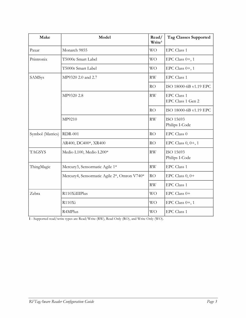
Supported RFID Readers You need one or more RFID readers to use RFTagAware. RFTagAware supports the makes and models of readers shown in the table below. The reader models marked with an asterisk (*) have substantially similar command sets and capabilities as others in the same row, but they have not been as extensively tested. Please contact your technical support representative if you encounter any issues with these reader models. If you do not have a reader, you can use the reader simulator provided with RFTagAware. Out of the box, it runs on any workstation and simulates a ThingMagic Mercury4 reader; with minor editing it can simulate a Printronix reader. The reader simulator is useful for software evaluation, application development, and debugging. We are committed to providing support for new makes and models of readers as they become available, so check with your sales representative if your selected reader does not appear in this list.
Make Model Read/ Write¹
Tag Classes Supported
Accraply ALX-92X series WO EPC Class 1
ALR-9750 (Nanoscanner) 915 MHz RFID RW EPC Class 1
ALR-9780 915 MHz RFID ALR-8780 866 MHz RFID*
RW EPC Class 1
ALR-9780 915 MHz RFID RO EPC Class 1 Gen 2
Alien
ALR-9800 RO EPC Class 0, 1 EPC Class 1 Gen 2
Avery 6405 WO EPC Class 1
RO EPC Class 0 MPR-2010AN, MPR-2080*
RW EPC Class 0+, 1
AWID
MPR-2010AN RW EPC Class 1 Gen 2
CAEN A928 RW ISO 18000-6B
DataLogic DS6300-105-010 RO N/A (bar code reader)
Escort Memory Systems
LRP820S, LRP2000 RO ISO 15693
Identec Solutions i-CARD 3 RO ILR i-Q and i-D (active tags)
Intermec Intellitag IF5 RW Intellitag G1 ISO 18000-6B EPC Class 1 Gen 2
RFTagAware Reader Configuration Guide Page 3
Make Model Read/
Write¹ Tag Classes Supported
Paxar Monarch 9855 WO EPC Class 1
T5000e Smart Label WO EPC Class 0+, 1 Printronix
T5000r Smart Label WO EPC Class 0+, 1
RW EPC Class 1 MP9320 2.0 and 2.7
RO ISO 18000-6B v1.19 EPC
RW EPC Class 1 EPC Class 1 Gen 2
MP9320 2.8
RO ISO 18000-6B v1.19 EPC
SAMSys
MP9210 RW ISO 15693 Philips I-Code
RDR-001 RO EPC Class 0 Symbol (Matrics)
AR400, DC400*, XR400 RO EPC Class 0, 0+, 1
TAGSYS Medio L100, Medio L200* RW ISO 15693 Philips I-Code
Mercury3, Sensormatic Agile 1* RW EPC Class 1
RO EPC Class 0, 0+
ThingMagic
Mercury4, Sensormatic Agile 2*, Omron V740*
RW EPC Class 1
R110XiIIIPlus WO EPC Class 0+
R110Xi WO EPC Class 0+, 1
Zebra
R4MPlus WO EPC Class 1 1 - Supported read/write types are Read/Write (RW), Read Only (RO), and Write Only (WO).
Page 4 RFTagAware Reader Configuration Guide
Configuring Physical Readers Some readers may require specific configuration prior to use with RFTagAware. You can configure RFTagAware to communicate with supported readers in one of two ways:
• (new for RFTagAware 1.3) Edit the reader configuration information using the RFID Devices pane on the Administration Console (the default for new RFTagAware installations).
• Edit the edge.props file directly to configure these devices. (This is the default for RFTagAware installations prior to version 1.3.) This file is a Java properties file used to configure the Edge Server. It is located in the etc subdirectory of the RFTagAware installation directory.
Configuration properties consist of a name (shown in the Property Name column of the tables in this document) and a value (described in the Property Value and Description column of those same tables). When written out in the edge.props file, they will appear in the following format: com.connecterra.ale.reader.<phys reader name>.<property name>=<property value> If you are using the Administration Console to add and configure readers, the configuration dialog will contain reader-specific fields to enter information into. In this case, no information will be written to the edge.props file; instead, the configuration information you enter will be saved in the persistence store kept by the Edge Server. See Chapters 2 and 3 of the RFTagAware Deployment Guide for more information on reader configuration procedures.
RFTagAware Reader Configuration Guide Page 5
Accraply
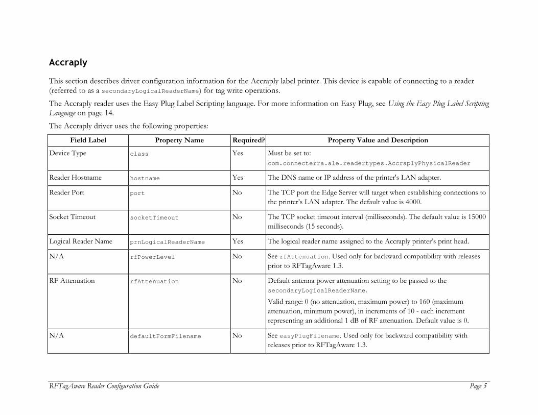
This section describes driver configuration information for the Accraply label printer. This device is capable of connecting to a reader (referred to as a secondaryLogicalReaderName) for tag write operations. The Accraply reader uses the Easy Plug Label Scripting language. For more information on Easy Plug, see Using the Easy Plug Label Scripting Language on page 14. The Accraply driver uses the following properties:
Field Label Property Name Required? Property Value and Description
Device Type class Yes Must be set to: com.connecterra.ale.readertypes.AccraplyPhysicalReader
Reader Hostname hostname Yes The DNS name or IP address of the printer's LAN adapter.
Reader Port port No The TCP port the Edge Server will target when establishing connections to the printer’s LAN adapter. The default value is 4000.
Socket Timeout socketTimeout No The TCP socket timeout interval (milliseconds). The default value is 15000 milliseconds (15 seconds).
Logical Reader Name prnLogicalReaderName Yes The logical reader name assigned to the Accraply printer’s print head.
N/A rfPowerLevel No See rfAttenuation. Used only for backward compatibility with releases prior to RFTagAware 1.3.
RF Attenuation rfAttenuation No Default antenna power attenuation setting to be passed to the secondaryLogicalReaderName. Valid range: 0 (no attenuation, maximum power) to 160 (maximum attenuation, minimum power), in increments of 10 - each increment representing an additional 1 dB of RF attenuation. Default value is 0.
N/A defaultFormFilename No See easyPlugFilename. Used only for backward compatibility with releases prior to RFTagAware 1.3.
Page 6 RFTagAware Reader Configuration Guide
Field Label Property Name Required? Property Value and Description
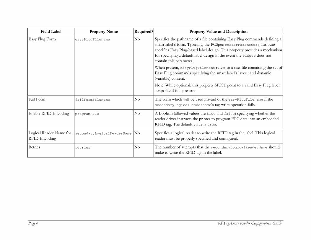
Easy Plug Form easyPlugFilename No Specifies the pathname of a file containing Easy Plug commands defining a smart label’s form. Typically, the PCSpec readerParameters attribute specifies Easy Plug-based label design. This property provides a mechanism for specifying a default label design in the event the PCSpec does not contain this parameter. When present, easyPlugFilename refers to a text file containing the set of Easy Plug commands specifying the smart label’s layout and dynamic (variable) content. Note: While optional, this property MUST point to a valid Easy Plug label script file if it is present.
Fail Form failFormFilename No The form which will be used instead of the easyPlugFilename if the secondaryLogicalReaderName’s tag write operation fails.
Enable RFID Encoding programRFID No A Boolean (allowed values are true and false) specifying whether the reader driver instructs the printer to program EPC data into an embedded RFID tag. The default value is true.
Logical Reader Name for RFID Encoding
secondaryLogicalReaderName No Specifies a logical reader to write the RFID tag in the label. This logical reader must be properly specified and configured.
Retries retries No The number of attempts that the secondaryLogicalReaderName should make to write the RFID tag in the label.

RFTagAware Reader Configuration Guide Page 7
Alien
RFTagAware uses two Alien reader drivers:
• Alien ALR-9750 – Use this driver for the Alien ALR-9750 (Nanoscanner 915 MHz) RFID reader.
• Alien ALR-9780 – Use this driver for the Alien ALR-9780 and ALR-8780 RFID readers.
Alien ALR-9750
This driver is used to interface the RFTagAware Edge Server with an Alien Technology ALR-9750 (Nanoscanner 915 MHz) RFID Reader. The reader driver implements Alien’s text-based communications protocol for configuring and operating its RFID readers. This text-based reader/ host protocol is specified in the Nanoscanner Reader User Guide (Alien Doc # 8101024-000 Rev B). The Alien ALR-9750 reader driver uses the following properties:
Field Label Property Name Required? Property Value and Description
Device Type class Yes For backward compatibility with releases prior to RFTagAware 1.1.2, set to: com.connecterra.ale.readertypes. AlienReaderGroup Otherwise, set to: com.connecterra.ale.readertypes. AlienALR9750PhysicalReader
Reader Hostname hostname Yes The DNS name or IP address of the Alien reader.
Reader Port port No The TCP port the Edge Server will use when establishing connections to the Alien Reader. The default is 23.
Default Rate defaultRate Yes The period (in milliseconds) between the start of one read cycle and the start of the next. Note that if multiple logical readers are simultaneously active, then each logical reader will be read at an interval equal to the defaultRate times the number of logical readers.

Page 8 RFTagAware Reader Configuration Guide
Field Label Property Name Required? Property Value and Description
Socket Timeout socketTimeout No The TCP socket timeout interval (milliseconds). The integer property value must be greater than or equal to 0. A timeout of 0 is interpreted as an infinite timeout. The default is 15000 milliseconds (15 seconds).
User Name username Yes The username the Edge Server will use for gaining access to the Alien reader. Must be the same as the username you configured when setting up the Alien reader. Note: The username is case sensitive and must be entirely lowercase.
Password password Yes The password the Edge Server will use for gaining access to the Alien reader. Must be the same as the password you configured when setting up the Alien reader. Note: The password is case sensitive and must be entirely lowercase.
Disable Programming Cycle Check disableProgrammingCycleCheck No An optional Boolean property (allowed values are true and false) specifying whether the driver disables the “Check Operation” (verification that there is a single tag in an antenna's field prior to conducting a tag programming operation). The default value is false, meaning the driver conducts the Check Operation.
Antenna 0 Logical Reader Name Antenna 1 Logical Reader Name
uhf1LogicalReaderName uhf2LogicalReaderName
No * (see descr.)
Specifies the logical reader name for each UHF antenna. At least one logical reader name must be specified or the Edge Server will generate an error on startup.
The Alien reader obtains its IP network configuration dynamically via DHCP, or statically through one of the reader's configuration interfaces. Refer to the Alien Nanoscanner Reader User Guide for further details. The Edge Server’s Alien reader driver assumes the Alien reader has also been configured, through Alien’s web interface or command line interface, with the following configuration settings. These configuration settings must be saved to the reader’s flash memory so that reader reboots do not result in their loss.

RFTagAware Reader Configuration Guide Page 9
Alien>Set Username=<username> Alien>Set Password=<password>
Alien ALR-9780
This driver is used to interface the RFTagAware Edge Server with two models of Alien Technology readers: the ALR-9780 915 MHz RFID reader and the ALR-8780 866 MHz RFID Reader. The reader driver implements Alien’s text-based communications protocol for configuring and operating its RFID readers. This text-based reader/host protocol is specified in the ALR-9780 Reader Interface Guide (Alien Doc # 8101938-000 Rev 01). The Alien ALR-9780 reader driver uses the following properties:
Field Label Property Name Required? Property Value and Description
Device Type class Yes For backward compatibility with releases prior to RFTagAware 1.1.2, set to: com.connecterra.ale. readertypes.AlienALR9780Group Otherwise, set to: com.connecterra.ale. readertypes.AlienALR9780PhysicalReader
Reader Hostname hostname Yes The DNS name or IP address of the Alien reader.
Reader Port port No The TCP port the Edge Server will use when establishing connections to the Alien Reader. The default is 23.
Default Rate defaultRate Yes The period (in milliseconds) between the start of one read cycle and the start of the next. Note that if multiple logical readers are simultaneously active, then each logical reader will be read at an interval equal to the defaultRate times the number of logical readers.
Socket Timeout socketTimeout No The TCP socket timeout interval (milliseconds). The integer property value must be greater than or equal to 0. A timeout of 0 is interpreted as an infinite timeout. The default is 15000 milliseconds (15 seconds).
Page 10 RFTagAware Reader Configuration Guide
Field Label Property Name Required? Property Value and Description
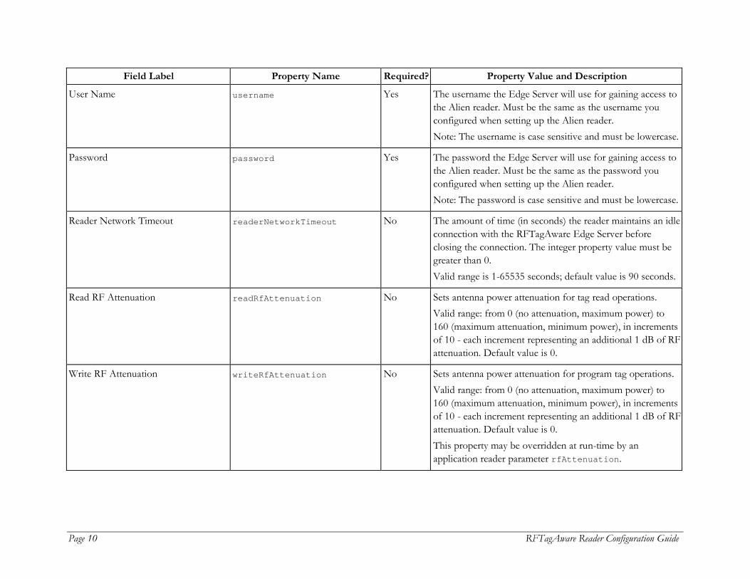
User Name username Yes The username the Edge Server will use for gaining access to the Alien reader. Must be the same as the username you configured when setting up the Alien reader. Note: The username is case sensitive and must be lowercase.
Password password Yes The password the Edge Server will use for gaining access to the Alien reader. Must be the same as the password you configured when setting up the Alien reader. Note: The password is case sensitive and must be lowercase.
Reader Network Timeout readerNetworkTimeout No The amount of time (in seconds) the reader maintains an idle connection with the RFTagAware Edge Server before closing the connection. The integer property value must be greater than 0. Valid range is 1-65535 seconds; default value is 90 seconds.
Read RF Attenuation readRfAttenuation No Sets antenna power attenuation for tag read operations. Valid range: from 0 (no attenuation, maximum power) to 160 (maximum attenuation, minimum power), in increments of 10 - each increment representing an additional 1 dB of RF attenuation. Default value is 0.
Write RF Attenuation writeRfAttenuation No Sets antenna power attenuation for program tag operations. Valid range: from 0 (no attenuation, maximum power) to 160 (maximum attenuation, minimum power), in increments of 10 - each increment representing an additional 1 dB of RF attenuation. Default value is 0. This property may be overridden at run-time by an application reader parameter rfAttenuation.
RFTagAware Reader Configuration Guide Page 11
Field Label Property Name Required? Property Value and Description
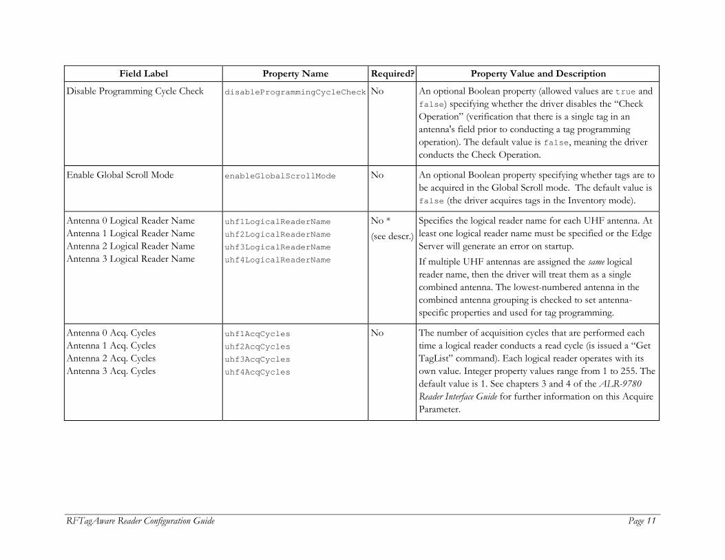
Disable Programming Cycle Check disableProgrammingCycleCheck No An optional Boolean property (allowed values are true and false) specifying whether the driver disables the “Check Operation” (verification that there is a single tag in an antenna's field prior to conducting a tag programming operation). The default value is false, meaning the driver conducts the Check Operation.
Enable Global Scroll Mode enableGlobalScrollMode No An optional Boolean property specifying whether tags are to be acquired in the Global Scroll mode. The default value is false (the driver acquires tags in the Inventory mode).
Antenna 0 Logical Reader Name Antenna 1 Logical Reader Name Antenna 2 Logical Reader Name Antenna 3 Logical Reader Name
uhf1LogicalReaderName uhf2LogicalReaderName uhf3LogicalReaderName uhf4LogicalReaderName
No * (see descr.)
Specifies the logical reader name for each UHF antenna. At least one logical reader name must be specified or the Edge Server will generate an error on startup. If multiple UHF antennas are assigned the same logical reader name, then the driver will treat them as a single combined antenna. The lowest-numbered antenna in the combined antenna grouping is checked to set antenna-specific properties and used for tag programming.
Antenna 0 Acq. Cycles Antenna 1 Acq. Cycles Antenna 2 Acq. Cycles Antenna 3 Acq. Cycles
uhf1AcqCycles uhf2AcqCycles uhf3AcqCycles uhf4AcqCycles
No The number of acquisition cycles that are performed each time a logical reader conducts a read cycle (is issued a “Get TagList” command). Each logical reader operates with its own value. Integer property values range from 1 to 255. The default value is 1. See chapters 3 and 4 of the ALR-9780 Reader Interface Guide for further information on this Acquire Parameter.
Page 12 RFTagAware Reader Configuration Guide
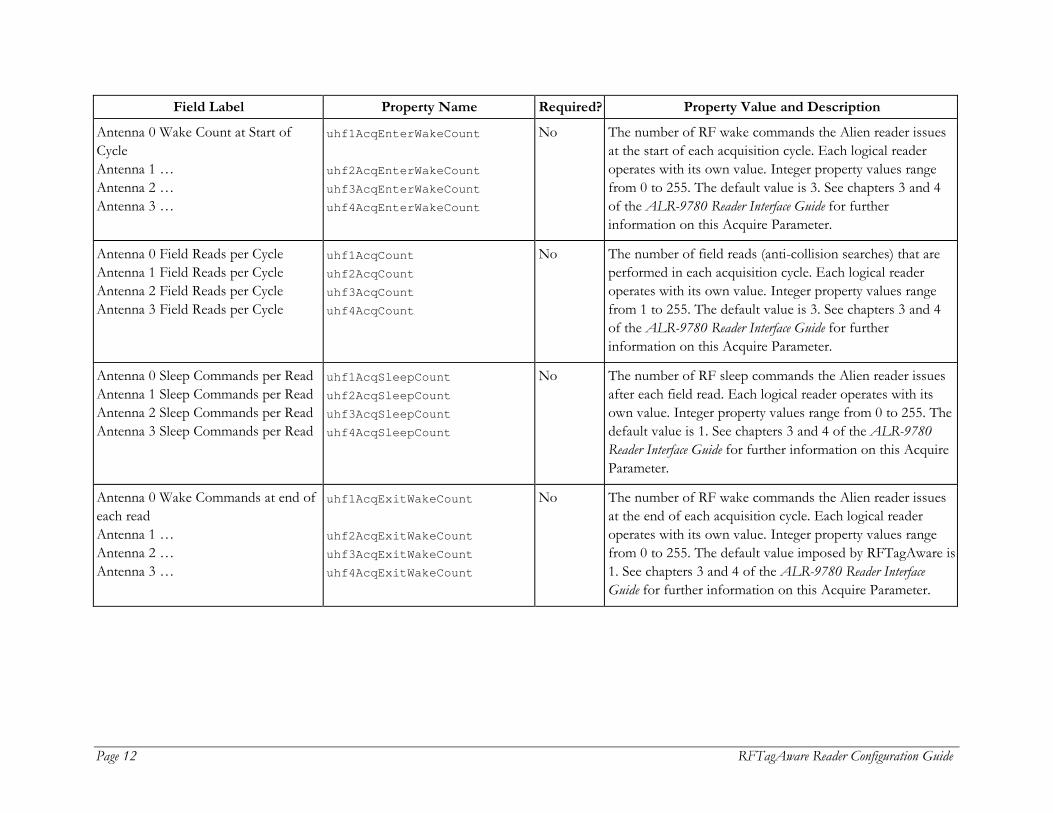
Field Label Property Name Required? Property Value and Description
Antenna 0 Wake Count at Start of Cycle Antenna 1 … Antenna 2 … Antenna 3 …
uhf1AcqEnterWakeCount uhf2AcqEnterWakeCount uhf3AcqEnterWakeCount uhf4AcqEnterWakeCount
No The number of RF wake commands the Alien reader issues at the start of each acquisition cycle. Each logical reader operates with its own value. Integer property values range from 0 to 255. The default value is 3. See chapters 3 and 4 of the ALR-9780 Reader Interface Guide for further information on this Acquire Parameter.
Antenna 0 Field Reads per Cycle Antenna 1 Field Reads per Cycle Antenna 2 Field Reads per Cycle Antenna 3 Field Reads per Cycle
uhf1AcqCount uhf2AcqCount uhf3AcqCount uhf4AcqCount
No The number of field reads (anti-collision searches) that are performed in each acquisition cycle. Each logical reader operates with its own value. Integer property values range from 1 to 255. The default value is 3. See chapters 3 and 4 of the ALR-9780 Reader Interface Guide for further information on this Acquire Parameter.
Antenna 0 Sleep Commands per Read Antenna 1 Sleep Commands per Read Antenna 2 Sleep Commands per Read Antenna 3 Sleep Commands per Read
uhf1AcqSleepCount uhf2AcqSleepCount uhf3AcqSleepCount uhf4AcqSleepCount
No The number of RF sleep commands the Alien reader issues after each field read. Each logical reader operates with its own value. Integer property values range from 0 to 255. The default value is 1. See chapters 3 and 4 of the ALR-9780 Reader Interface Guide for further information on this Acquire Parameter.
Antenna 0 Wake Commands at end of each read Antenna 1 … Antenna 2 … Antenna 3 …
uhf1AcqExitWakeCount uhf2AcqExitWakeCount uhf3AcqExitWakeCount uhf4AcqExitWakeCount
No The number of RF wake commands the Alien reader issues at the end of each acquisition cycle. Each logical reader operates with its own value. Integer property values range from 0 to 255. The default value imposed by RFTagAware is 1. See chapters 3 and 4 of the ALR-9780 Reader Interface Guide for further information on this Acquire Parameter.

RFTagAware Reader Configuration Guide Page 13
Field Label Property Name Required? Property Value and Description
Antenna 0 Field Inventory Timeout Antenna 1 Field Inventory Timeout Antenna 2 Field Inventory Timeout Antenna 3 Field Inventory Timeout
uhf1GetTagListTimeout uhf2GetTagListTimeout uhf3GetTagListTimeout uhf4GetTagListTimeout
No The timeouts (in milliseconds) for field inventories (Alien Reader “Get TagList” commands). Each logical reader operates with its own timeout value. This configuration parameter, rather than the socketTimeout property, will serve as the socket timeout value when the Edge Server is awaiting a response to a “Get TagList” command. The integer property value must be greater than or equal to 0. A timeout of 0 is interpreted as an infinite timeout. The default value is the value of the socketTimeout property (or its default).
Stack Light A Logical Reader Name leftStackLightLogicalReader No Specifies a logical reader to control the left stack light. See Appendix A for more information on stack light configuration.
Red Light IO Mask redLightIOMask No Defines GPIO port output lines to control the red light on the stack. The valid range is 0-15; the default value is 0.
Green Light IO Mask greenLightIOMask No Defines GPIO port output lines to control the green part of the stack light. The valid range is 0-15; the default value is 0.
Stack Light B Logical Reader Name rightStackLightLogicalReader No Specifies a logical reader to control the right stack light. See Appendix A for more information on stack light configuration.

Page 14 RFTagAware Reader Configuration Guide
Field Label Property Name Required? Property Value and Description
List of Protocols rfProtocols No A blank-separated list of RF protocols. Alien ALR-9780 is a multi-protocol reader. To improve efficiency, the read operation will only attempt to collect tags encoded with the specified protocols. At present, valid values are: All epcClass1 epcClass1Gen2 The default value is All.
The Alien reader obtains its IP network configuration dynamically via DHCP, or statically through one of the reader’s configuration interfaces. Refer to the Alien Reader Interface Guide for further details. The Edge Server’s Alien reader driver assumes the Alien reader has also been configured, through Alien's web interface or command line interface, with the following configuration settings. These configuration settings must be saved to the reader's flash memory so that reader reboots do not result in their loss. Alien>Set Username=<username> Alien>Set Password=<password>
Alien ALR-9800
This driver is used to interface the RFTagAware Edge Server with the Alien Technology ALR-9800 reader. The Alien ALR-9800 reader driver uses the same properties as the ALR-9780, with the following exceptions:
• The Device Type property value in edge.props is set to com.connecterra.ale.readertypes.AlienALR9800PhysicalReader
• The List of Protocols values include epcClass0.

RFTagAware Reader Configuration Guide Page 15
Avery
This section describes driver configuration information for the Avery 6405 RFID label printer. The printer supports the writing (programming) of Class 1 tags embedded within label stock (“smart labels”) and the printing of those labels. The Avery 6405 reader driver uses the following properties:
Field Label Property Name Required? Property Value and Description
Device Type class Yes Must be set to: com.connecterra.ale.readertypes.Avery6405PhysicalReader
Reader Hostname hostname Yes The DNS name or IP address of the printer's LAN adapter.
Reader Port port No The TCP port the Edge Server will target when establishing connections to the printer’s LAN adapter. The default value is 4000.
Socket Timeout socketTimeout No The TCP socket timeout interval (milliseconds). The default value is 15000 milliseconds (15 seconds).
N/A defaultFormFilename No See easyPlugFilename. Used only for backward compatibility with releases prior to RFTagAware 1.3.
Easy Plug Form easyPlugFilename No Specifies the pathname of a file containing Easy Plug commands defining a smart label’s form. Typically, the PCSpec readerParameters attribute specifies Easy Plug-based label design. This property provides a mechanism for specifying a default label design in the event the PCSpec does not contain this parameter. When present, easyPlugFilename refers to a text file containing the set of Easy Plug commands specifying the smart label’s layout and dynamic (variable) content. Note: While optional, this property MUST point to a valid Easy Plug label script file if it is present.

Page 16 RFTagAware Reader Configuration Guide
Field Label Property Name Required? Property Value and Description
Enable RFID Encoding programRFID No A Boolean (allowed values are true and false) specifying whether the reader driver instructs the printer to program EPC data into an embedded RFID tag. The default value is true.
Logical Reader Name uhf1LogicalReaderName Yes The logical reader name assigned to the Avery printer’s single integrated UHF antenna.
Retries retries No Defines the number of labels to retry in case of a failed RFID operation. The valid range is 1 through 10. The default value is 3.
Using the Easy Plug Label Scripting Language
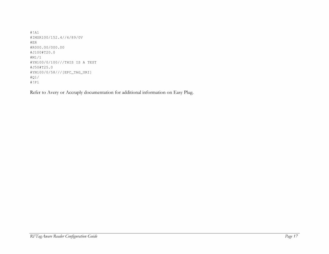
Easy Plug is a scripting language for specifying the layout and contents of printed labels. Easy Plug is described in detail in the Avery document, Manual Easy Plug, Release 3.00, 11/2003. Commands specific to the Avery 6405 are described in the document, How to RFID with Avery 6405. The Avery 6405 and Accraply smart label printer drivers send their printers a separate collection of Easy Plug commands with each “smart label” (a printed label with an embedded RFID tag) to be printed and programmed. Users specify a smart label’s Easy Plug commands when defining a PCSpec (see the RFTagAware Programmer Guide). A PCSpec’s readerParameters field carries the Easy Plug script as a String object; the corresponding reader parameter name is easyPlugScript (or one of easyPlugScript.accraply or easyPlugScript.avery if your RFTagAware installation supports more than one device that uses EasyPlug). For backward compatibility with releases prior to RFTagAware 1.3, use the reader parameter names com.connecterra.ale.readertypes.avery.eplScript or com.connecterra.ale.readertypes.accraply.eplScript. As an alternative to specifying Easy Plug within a PCSpec, the Edge Server administrator may specify a default Easy Plug script using the reader driver’s easyPlugFilename property. The easyPlugFilename property provides a mechanism for specifying Easy Plug commands that serve as a default label design in the event the PCSpec’s readerParameters field does not carry a key/value pair containing an Easy Plug script. The Easy Plug script, whether defined within the PCSpec or contained in a file identified by the easyPlugFilename property, must contain only Easy Plug commands. Here is an example script:
RFTagAware Reader Configuration Guide Page 17
#!A1 #IMSR100/152.4//6/89/0V #ER #R000.00/000.00 #J100#T20.0 #M1/1 #YN100/0/100///THIS IS A TEST #J50#T25.0 #YN100/0/58///[EPC_TAG_URI] #Q1/ #!P1 Refer to Avery or Accraply documentation for additional information on Easy Plug.
Page 18 RFTagAware Reader Configuration Guide
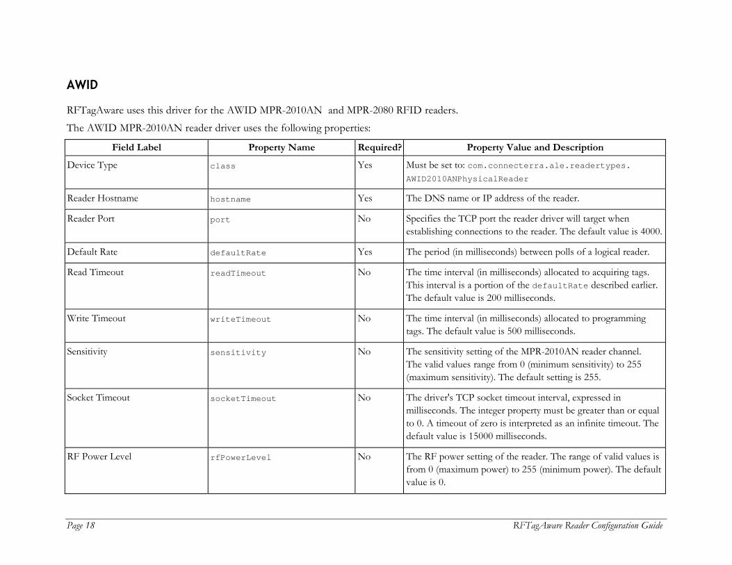
AWID
RFTagAware uses this driver for the AWID MPR-2010AN and MPR-2080 RFID readers. The AWID MPR-2010AN reader driver uses the following properties:
Field Label Property Name Required? Property Value and Description
Device Type class Yes Must be set to: com.connecterra.ale.readertypes. AWID2010ANPhysicalReader
Reader Hostname hostname Yes The DNS name or IP address of the reader.
Reader Port port No Specifies the TCP port the reader driver will target when establishing connections to the reader. The default value is 4000.
Default Rate defaultRate Yes The period (in milliseconds) between polls of a logical reader.
Read Timeout readTimeout No The time interval (in milliseconds) allocated to acquiring tags. This interval is a portion of the defaultRate described earlier. The default value is 200 milliseconds.
Write Timeout writeTimeout No The time interval (in milliseconds) allocated to programming tags. The default value is 500 milliseconds.
Sensitivity sensitivity No The sensitivity setting of the MPR-2010AN reader channel. The valid values range from 0 (minimum sensitivity) to 255 (maximum sensitivity). The default setting is 255.
Socket Timeout socketTimeout No The driver's TCP socket timeout interval, expressed in milliseconds. The integer property must be greater than or equal to 0. A timeout of zero is interpreted as an infinite timeout. The default value is 15000 milliseconds.
RF Power Level rfPowerLevel No The RF power setting of the reader. The range of valid values is from 0 (maximum power) to 255 (minimum power). The default value is 0.
RFTagAware Reader Configuration Guide Page 19
Field Label Property Name Required? Property Value and Description
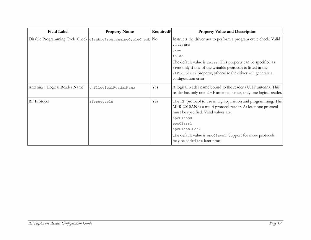
Disable Programming Cycle Check disableProgrammingCycleCheck No Instructs the driver not to perform a program cycle check. Valid values are: true false The default value is false. This property can be specified as true only if one of the writable protocols is listed in the rfProtocols property, otherwise the driver will generate a configuration error.
Antenna 1 Logical Reader Name uhf1LogicalReaderName Yes A logical reader name bound to the reader's UHF antenna. This reader has only one UHF antenna; hence, only one logical reader.
RF Protocol rfProtocols Yes The RF protocol to use in tag acquisition and programming. The MPR-2010AN is a multi-protocol reader. At least one protocol must be specified. Valid values are: epcClass0 epcClass1 epcClass1Gen2 The default value is epcClass1. Support for more protocols may be added at a later time.
Page 20 RFTagAware Reader Configuration Guide
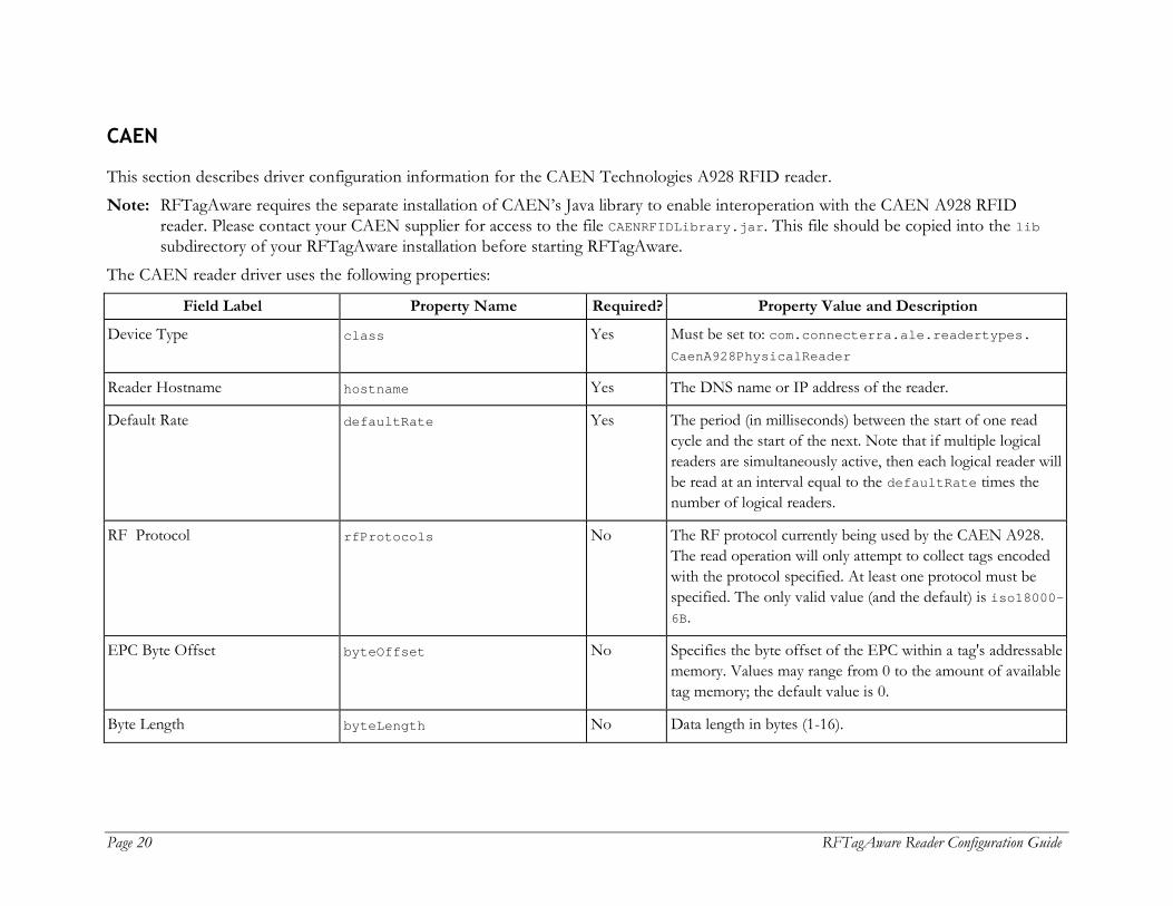
CAEN
This section describes driver configuration information for the CAEN Technologies A928 RFID reader. Note: RFTagAware requires the separate installation of CAEN’s Java library to enable interoperation with the CAEN A928 RFID
reader. Please contact your CAEN supplier for access to the file CAENRFIDLibrary.jar. This file should be copied into the lib subdirectory of your RFTagAware installation before starting RFTagAware.
The CAEN reader driver uses the following properties:
Field Label Property Name Required? Property Value and Description
Device Type class Yes Must be set to: com.connecterra.ale.readertypes. CaenA928PhysicalReader
Reader Hostname hostname Yes The DNS name or IP address of the reader.
Default Rate defaultRate Yes The period (in milliseconds) between the start of one read cycle and the start of the next. Note that if multiple logical readers are simultaneously active, then each logical reader will be read at an interval equal to the defaultRate times the number of logical readers.
RF Protocol rfProtocols No The RF protocol currently being used by the CAEN A928. The read operation will only attempt to collect tags encoded with the protocol specified. At least one protocol must be specified. The only valid value (and the default) is iso18000-6B.
EPC Byte Offset byteOffset No Specifies the byte offset of the EPC within a tag's addressable memory. Values may range from 0 to the amount of available tag memory; the default value is 0.
Byte Length byteLength No Data length in bytes (1-16).

RFTagAware Reader Configuration Guide Page 21
Field Label Property Name Required? Property Value and Description
Antenna 0 Logical Reader Name Antenna 1 Logical Reader Name Antenna 2 Logical Reader Name Antenna 3 Logical Reader Name
uhf1LogicalReaderName uhf2LogicalReaderName uhf3LogicalReaderName uhf4LogicalReaderName
No * (see descr.)
Specifies the logical reader name for each UHF antenna. At least one logical reader name must be specified or the Edge Server will generate an error on startup.
Read RF Power, mW uhf1ReadRfPower uhf2ReadRfPower uhf3ReadRfPower uhf4ReadRfPower
No The strength of the RF signal used to read tags, in milliwatts. Valid values are 0-4000; the default value is 500. The maximum value allowable is determined by the reader; see the reader documentation for more information.
Write RF Power, mW uhf1WriteRfPower uhf2WriteRfPower uhf3WriteRfPower uhf4WriteRfPower
No The strength of the RF signal used to write tags, in milliwatts. Valid values are 0-4000; the default value is 500. The maximum value allowable is determined by the reader; see the reader documentation for more information.
IO Gate 1 IO Gate 2 IO Gate 3 IO Gate 4
ioGateLine1 ioGateLine2 ioGateLine3 ioGateLine4
No This field should be left blank.
IO Gate Logical Reader Name ioGateLine1.logicalReaderName ioGateLine2.logicalReaderName ioGateLine3.logicalReaderName ioGateLine4.logicalReaderName
No Specifies the logical reader controlled by this IO line. The value for this property must match one of the configured Logical Reader Names.
IO Mask ioGateLine1.ioMask ioGateLine2.ioMask ioGateLine3.ioMask ioGateLine4.ioMask
No Specifies the IO mask associated with this IO line. Values range from 0 to 15. A value of 0 means "disable IO gating signal".
Page 22 RFTagAware Reader Configuration Guide
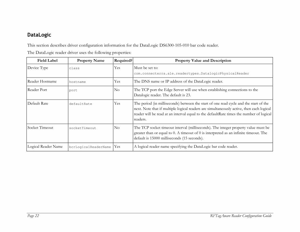
DataLogic
This section describes driver configuration information for the DataLogic DS6300-105-010 bar code reader. The DataLogic reader driver uses the following properties:
Field Label Property Name Required? Property Value and Description
Device Type class Yes Must be set to: com.connecterra.ale.readertypes.DatalogicPhysicalReader
Reader Hostname hostname Yes The DNS name or IP address of the DataLogic reader.
Reader Port port No The TCP port the Edge Server will use when establishing connections to the Datalogic reader. The default is 23.
Default Rate defaultRate Yes The period (in milliseconds) between the start of one read cycle and the start of the next. Note that if multiple logical readers are simultaneously active, then each logical reader will be read at an interval equal to the defaultRate times the number of logical readers.
Socket Timeout socketTimeout No The TCP socket timeout interval (milliseconds). The integer property value must be greater than or equal to 0. A timeout of 0 is interpreted as an infinite timeout. The default is 15000 milliseconds (15 seconds).
Logical Reader Name bcrLogicalReaderName Yes A logical reader name specifying the DataLogic bar code reader.

RFTagAware Reader Configuration Guide Page 23
Escort Memory Systems (EMS)
This section describes driver configuration information for the Escort Memory Systems (EMS) LRP820S and LRP2000 readers. The EMS reader driver uses the following properties:
Field Label Property Name Required? Property Value and Description
Device Type class Yes For backward compatibility with releases prior to RFTagAware 1.1.2, set to: com.connecterra.ale.readertypes.EMSLRPGroup Otherwise, set to: com.connecterra.ale.readertypes.EMSLRPPhysicalReader
N/A gatewayName No See hostname. Used only for backward compatibility with releases prior to RFTagAware 1.3.
Reader Hostname hostname Yes The DNS name or IP address of the MOXA serial-to-Ethernet adapter to which the reader is connected.
N/A gatewayPort No See port. Used only for backward compatibility with releases prior to RFTagAware 1.3.
Reader Port port No The TCP port the Edge Server will use when establishing connections to the MOXA serial-to-Ethernet adapter. The default value is 8080
Default Rate defaultRate Yes The period (in milliseconds) between the start of one read cycle and the start of the next. Note that if multiple logical readers are simultaneously active, then each logical reader will be read at an interval equal to the defaultRate times the number of logical readers.
Socket Timeout socketTimeout No The TCP socket timeout interval (milliseconds). The integer property value must be greater than or equal to 0. A timeout of 0 is interpreted as an infinite timeout. The default is 15000 milliseconds (15 seconds).
Page 24 RFTagAware Reader Configuration Guide
Field Label Property Name Required? Property Value and Description
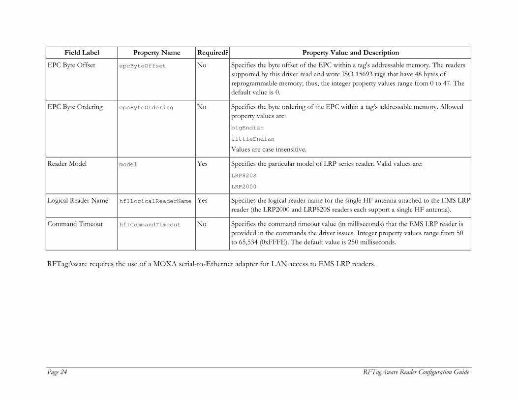
EPC Byte Offset epcByteOffset No Specifies the byte offset of the EPC within a tag's addressable memory. The readers supported by this driver read and write ISO 15693 tags that have 48 bytes of reprogrammable memory; thus, the integer property values range from 0 to 47. The default value is 0.
EPC Byte Ordering epcByteOrdering No Specifies the byte ordering of the EPC within a tag's addressable memory. Allowed property values are: bigEndian
littleEndian Values are case insensitive.
Reader Model model Yes Specifies the particular model of LRP series reader. Valid values are: LRP820S
LRP2000
Logical Reader Name hf1LogicalReaderName Yes Specifies the logical reader name for the single HF antenna attached to the EMS LRP reader (the LRP2000 and LRP820S readers each support a single HF antenna).
Command Timeout hf1CommandTimeout No Specifies the command timeout value (in milliseconds) that the EMS LRP reader is provided in the commands the driver issues. Integer property values range from 50 to 65,534 (0xFFFE). The default value is 250 milliseconds.
RFTagAware requires the use of a MOXA serial-to-Ethernet adapter for LAN access to EMS LRP readers.
RFTagAware Reader Configuration Guide Page 25
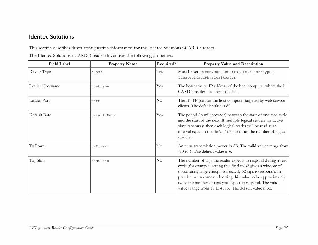
Identec Solutions
This section describes driver configuration information for the Identec Solutions i-CARD 3 reader. The Identec Solutions i-CARD 3 reader driver uses the following properties:
Field Label Property Name Required? Property Value and Description
Device Type class Yes Must be set to: com.connecterra.ale.readertypes. IdentecICardPhysicalReader
Reader Hostname hostname Yes The hostname or IP address of the host computer where the i-CARD 3 reader has been installed.
Reader Port port No The HTTP port on the host computer targeted by web service clients. The default value is 80.
Default Rate defaultRate Yes The period (in milliseconds) between the start of one read cycle and the start of the next. If multiple logical readers are active simultaneously, then each logical reader will be read at an interval equal to the defaultRate times the number of logical readers.
Tx Power txPower No Antenna transmission power in dB. The valid values range from -30 to 6. The default value is 6.
Tag Slots tagSlots No The number of tags the reader expects to respond during a read cycle (for example, setting this field to 32 gives a window of opportunity large enough for exactly 32 tags to respond). In practice, we recommend setting this value to be approximately twice the number of tags you expect to respond. The valid values range from 16 to 4096. The default value is 32.
Page 26 RFTagAware Reader Configuration Guide
Field Label Property Name Required? Property Value and Description
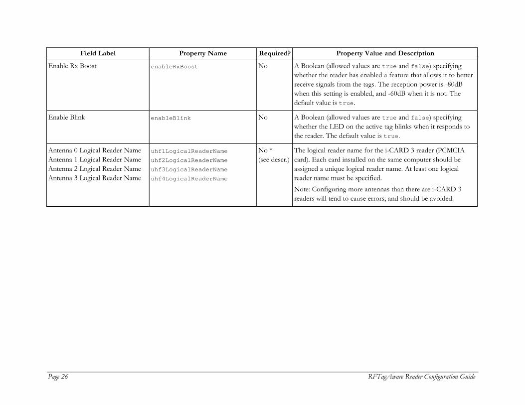
Enable Rx Boost enableRxBoost No A Boolean (allowed values are true and false) specifying whether the reader has enabled a feature that allows it to better receive signals from the tags. The reception power is -80dB when this setting is enabled, and -60dB when it is not. The default value is true.
Enable Blink enableBlink No A Boolean (allowed values are true and false) specifying whether the LED on the active tag blinks when it responds to the reader. The default value is true.
Antenna 0 Logical Reader Name Antenna 1 Logical Reader Name Antenna 2 Logical Reader Name Antenna 3 Logical Reader Name
uhf1LogicalReaderName uhf2LogicalReaderName uhf3LogicalReaderName uhf4LogicalReaderName
No * (see descr.)
The logical reader name for the i-CARD 3 reader (PCMCIA card). Each card installed on the same computer should be assigned a unique logical reader name. At least one logical reader name must be specified. Note: Configuring more antennas than there are i-CARD 3 readers will tend to cause errors, and should be avoided.

RFTagAware Reader Configuration Guide Page 27
Intermec
This section describes driver configuration information for the Intermec Intellitag IF5 reader. The Intermec Intellitag IF5 reader driver uses the following properties:
Field Label Property Name Required? Property Value and Description
Device Type class Yes Must be set to: com.connecterra.ale.readertypes. IntermecIF5PhysicalReader
Reader Hostname hostname Yes The DNS name or IP address of the printer.
Reader Port port No The TCP port the Edge Server will target when establishing connections to the reader. The default value is 2189.
Default Rate defaultRate Yes The period (in milliseconds) between the start of one read cycle and the start of the next. If multiple logical readers are active simultaneously, then each logical reader will be read at an interval equal to the defaultRate times the number of logical readers.
Socket Timeout socketTimeout No The TCP socket timeout interval (milliseconds). The default value is 15000 milliseconds (15 seconds). This value must be greater than 0.
RF Protocol rfProtocols No The RF protocol currently being used by the Intermec reader. The Intellitag IF5 is a multi-protocol reader. To improve efficiency, the read operation will only attempt to collect tags encoded with the specified protocols. At least one protocol must be specified. The valid values are: epcClass1Gen2 iso18000-6B MIXED The default value is MIXED.

Page 28 RFTagAware Reader Configuration Guide
Field Label Property Name Required? Property Value and Description
ID Tries idTries No Maximum number of identify attempts on a given tag. Values range from 1-255; the default value is 3.
Read Tries readTries No Maximum number of read attempts on a given tag. Values range from 1-255; the default value is 3.
Write Tries writeTries No Maximum number of write attempts on a given tag. Values range from 1-255; the default value is 3.
EPC Byte Offset byteOffset No Specifies the byte offset of the EPC within a tag's addressable memory. Values may range from 0 to the amount of available tag memory, minus the amount specified in byteLength (below); the default value is 0. When writing ISO18000-6B tags, this value should be equal to or greater than 8. When reading Class 1 Gen 2 tags this value should be left blank during reader configuration.
Byte Length byteLength No Data length in bytes (0-16). The default value is 8. When reading Class 1 Gen 2 tags this value should be left blank during reader configuration.
Enable V1.19 mode enableEPCv1.19 No Enables reading of EPC 1.19 tags. The default value is false. If this property is set to true, the RF Protocol property should be set to iso18000-6B.

RFTagAware Reader Configuration Guide Page 29
Field Label Property Name Required? Property Value and Description
Disable Programming Cycle Check disableProgrammingCycleCheck No An optional Boolean property (allowed values are true and false) specifying whether the driver disables the “Check Operation” (verification that there is a single tag in an antenna's field prior to conducting a tag programming operation). The default value is false, meaning the driver conducts the Check Operation. Note that if the check operation is disabled (this property value is set to true) and multiple tags are present in the antenna's field when conducting a tag programming operation, then all tags in the field will be programmed with the same EPC.
Antenna 0 Logical Reader Name Antenna 1 Logical Reader Name Antenna 2 Logical Reader Name Antenna 3 Logical Reader Name
uhf1LogicalReaderName uhf2LogicalReaderName uhf3LogicalReaderName uhf4LogicalReaderName
No * (see descr.)
Specifies the logical reader name for each antenna. At least one logical reader name must be specified. If one of these properties is left undefined, there will be no logical reader associated with the corresponding antenna, and that antenna will not be accessible via the ALE API.

Page 30 RFTagAware Reader Configuration Guide
Paxar
This section describes driver configuration information for the Paxar Monarch 9855 smart label printer. You will need to consult the Monarch® 9855™ RFID Printer Operator's Handbook and enable status polling to allow the printer to respond to status requests from RFTagAware. The Paxar Monarch 9855 reader driver uses the following properties:
Field Label Property Name Required? Property Value and Description
Device Type class Yes Must be set to: com.connecterra.ale.readertypes.Monarch9855PhysicalReader
Reader Hostname hostname Yes The DNS name or IP address of the printer.
Reader Port port No The TCP port the Edge Server will target when establishing connections to the printer. The printer default value is 9100.
Socket Timeout socketTimeout No The TCP socket timeout interval (milliseconds). The default value is 15000 milliseconds (15 seconds). This value must be greater than 0.
Logical Reader Name uhf1LogicalReaderName Yes The logical reader name assigned to the device’s single integrated UHF antenna.
Enable RFID Encoding programRFID No A Boolean (allowed values are true and false) specifying whether the reader driver instructs the printer to program EPC data into an embedded RFID tag. The default value is true.
MPCL Form mpclFilename No Specifies the pathname of a file containing MPCL commands defining a smart label's form. Typically the MPCL-based label design will be specified within the PCSpec's readerParameters attribute. This property provides a mechanism for specifying a default label design in the event the PCSpec does not contain Monarch 9855 reader parameters. When present, the Monarch reader parameters are a string containing the set of MPCL commands specifying a smart label's layout.

RFTagAware Reader Configuration Guide Page 31
Printronix
This section describes driver configuration information for the Printronix T5000e and T5000r series of label printers with integrated RFID UHF encoders. Although the Printronix device has a “reader driver,” it does not support tag reading. Instead, it supports the writing (programming) of Class 1 and Class 0+ tags embedded within label stock (“smart labels”) and the printing of those labels. The Printronix T5000e and T5000r reader drivers use the following properties:
Field Label Property Name Required? Property Value and Description
Device Type class Yes For backward compatibility with releases prior to RFTagAware 1.1.2, set to: com.connecterra.ale.readertypes.PrintronixT5000eGroup Otherwise, set to: com.connecterra.ale.readertypes.PrintronixT5000ePhysicalReader
Reader Hostname hostname Yes The DNS name or IP address of the printer’s LAN adapter.
Logical Reader Name uhf1LogicalReaderName Yes The logical reader name assigned to the Printronix device’s single integrated UHF antenna.
Enable Direct Connection for Label Printing
enablePrint No A Boolean (allowed values are true and false) specifying whether a direct connection to printer for label printing and RFID programming is enabled. The default value is true.
Reader Port port No The TCP port the Edge Server will target when establishing connections to the printer’s LAN adapter. The default value is 9100, the Printronix device’s factory default.
Socket Timeout socketTimeout No The TCP socket timeout interval (milliseconds). The default value is 15000 milliseconds (15 seconds).
Enable RFID Encoding programRFID No A Boolean (allowed values are true and false) specifying whether the reader driver instructs the printer to program EPC data into an embedded RFID tag. The default value is true.

Page 32 RFTagAware Reader Configuration Guide
Field Label Property Name Required? Property Value and Description
PGL Form pglFilename No Specifies the pathname of a file containing Printronix PGL commands defining a smart label’s form. Typically, the PCSpec readerParameters attribute specifies PGL-based label design. This property provides a mechanism for specifying a default label design in the event the PCSpec does not contain Printronix reader parameters. When present, pglFilename refers to a text file (label.pgl) containing the set of PGL create-mode commands specifying the smart label’s layout and non-EPC content. See Using the Printronix Graphics Language (below) for more information.
Enable GPIO Port Connection for Printer Status Monitoring
enableGPIO No An optional Boolean property (allowed values are true and false), specifying whether the GPIO port for printer status monitoring is enabled. The default value is false. If it is set to true, enter values for the next three properties to properly configure communications via the GPIO port.
GPIO Port gpioPort No The general-purpose I/O (GPIO) port used by the Edge Server to obtain printer status via the printer's Ethernet adapter. The default value is 3002. Note: The GPIO properties are only available for use after installing and configuring the GPIO Accessory Module, available from the manufacturer.
GPIO Port Heart Beat Timeout (ms)
gpioHeartBeatTimeout No The printer regularly sends “heartbeat” messages to the Edge Server to confirm connectivity. (Consult the manufacturer or printer documentation for information on how often these messages are sent.) This value defines how long, in milliseconds, the Edge Server will wait for a message before attempting to re-establish a connection with the printer. The default value is 10050. This property must be set to a value greater than the interval between heartbeat messages.
GPIO Message Content File
gpioMessageFile No The path and name of the file that defines Printronix GPIO messages and their associated message IDs. The contents of this file can be edited, but the file should always contain entries for Heart_Beat_Normal and Heart_Beat_Error messages. This file is based on Printronix’s GPIO message definition.

RFTagAware Reader Configuration Guide Page 33
Using the Printronix Graphics Language (PGL)
The Printronix Graphics Language (PGL) is a scripting language for specifying the layout and contents of printed labels. PGL is described in detail in the Printronix document, IGP/PGL Emulation for T5000e series Printers: Printronix Graphics Language Programmer's Reference Manual (Printronix document 750929-001E). The Printronix T5000e/T5000r smart label printer drivers send the printer a separate collection of PGL commands with each “smart label” (a printed label with an embedded RFID tag) to be printed and programmed. Users specify a smart label’s PGL commands when defining a PCSpec (see the RFTagAware Programmer Guide). A PCSpec’s readerParameters field carries the PGL script as a String object; the reader parameter name is pglScript. (For backward compatibility with releases prior to RFTagAware 1.3, use the reader parameter name com.connecterra.ale.readertypes.PrintronixT5000eGroup.pglScript.) As an alternative to specifying PGL within a PCSpec, the Edge Server administrator may specify a default PGL script using the Printronix reader driver’s pglFilename property. The pglFilename property provides a mechanism for specifying PGL commands that serve as a default label design in the event the PCSpec’s readerParameters field does not carry a key/value pair containing a PGL script. The PGL script, whether defined within the PCSpec or contained in a file identified by the pglFilename property, must only contain IGP/PGL Create Form mode commands. Below is an example PGL script: SCALE;DOT;200;200 FONT;FACE 92250 ALPHA POINT;60;50;8;8;*SHIP FROM:* POINT;90;50;10;10;*ACME* POINT;120;50;10;10;*Corporation* POINT;150;50;10;10;*P.O. Box 1000* POINT;180;50;10;10;*Dallas, TX75261* POINT;60;365;8;8;*SHIP TO:* POINT;90;365;10;10;*Retailer Distribution Center* POINT;120;365;10;10;*200 Main Street* POINT;150;365;10;10;*Springfield, MA01103* STOP HORZ 4;200;40;790 STOP

Page 34 RFTagAware Reader Configuration Guide
VERT 3;343;60;200 STOP ALPHA POINT;235;50;8;8;*(420)SHIP TO POSTAL CODE:* POINT;285;100;12;12;*(420) 01103* POINT;235;385;8;8;*CARRIER:* POINT;285;400;12;12;*Acme Freightways* POINT;330;400;10;10;*PRO: 1234* POINT;370;400;10;10;*B/L: 5678* STOP BARCODE C128C;XRD3:3:6:6:9:9:12:12;H7;283;75 *01103* STOP HORZ 4;425;40;790 STOP VERT 3;374;200;425 STOP ALPHA POINT;465;50;12;12;*EPC:* AF512;25;POINT;550;70;14;14 STOP HORZ 4;625;40;779 STOP ALPHA POINT;665;50;12;12;*SKU:* POINT;705;70;14;14;*ABC21270* STOP
RFTagAware Reader Configuration Guide Page 35
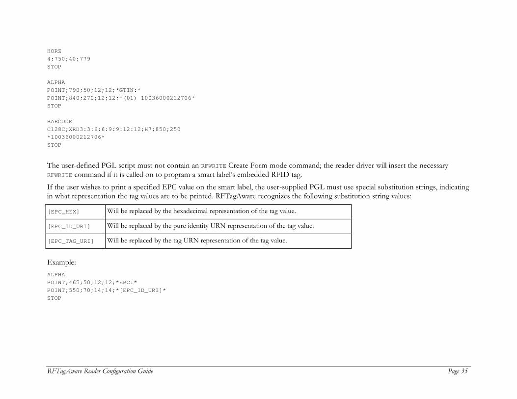
HORZ 4;750;40;779 STOP ALPHA POINT;790;50;12;12;*GTIN:* POINT;840;270;12;12;*(01) 10036000212706* STOP BARCODE C128C;XRD3:3:6:6:9:9:12:12;H7;850;250 *10036000212706* STOP The user-defined PGL script must not contain an RFWRITE Create Form mode command; the reader driver will insert the necessary RFWRITE command if it is called on to program a smart label’s embedded RFID tag. If the user wishes to print a specified EPC value on the smart label, the user-supplied PGL must use special substitution strings, indicating in what representation the tag values are to be printed. RFTagAware recognizes the following substitution string values:
[EPC_HEX] Will be replaced by the hexadecimal representation of the tag value.
[EPC_ID_URI] Will be replaced by the pure identity URN representation of the tag value.
[EPC_TAG_URI] Will be replaced by the tag URN representation of the tag value.
Example: ALPHA POINT;465;50;12;12;*EPC:* POINT;550;70;14;14;*[EPC_ID_URI]* STOP
Page 36 RFTagAware Reader Configuration Guide
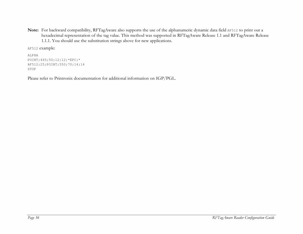
Note: For backward compatibility, RFTagAware also supports the use of the alphanumeric dynamic data field AF512 to print out a hexadecimal representation of the tag value. This method was supported in RFTagAware Release 1.1 and RFTagAware Release 1.1.1. You should use the substitution strings above for new applications.
AF512 example: ALPHA POINT;465;50;12;12;*EPC:* AF512;25;POINT;550;70;14;14 STOP Please refer to Printronix documentation for additional information on IGP/PGL.

RFTagAware Reader Configuration Guide Page 37
SAMSys
RFTagAware uses two SAMSys reader drivers:
• MP9320 – Use this driver for the SAMSys MP9230 reader, versions 2.0, 2.7, and 2.8.
• MP9210 – Use this driver for the SAMSys MP9210 reader.
MP9320
This section describes driver configuration information for the SAMSys MP9320 RFID reader. SAMSys MP9320 2.8 readers feature a single-color stack light, which requires no configuration. SAMSys MP9320 2.0 readers are serial devices and do not provide for Ethernet connectivity. To be used with RFTagAware, they require a serial to Ethernet adapter (such as the Digi Connect ME Module). The adapter serial port must be configured to 57600/8/1/N. The SAMSys MP9320 reader drivers use the following properties:
Field Label Property Name Required? Property Value and Description
Device Type class Yes Must be set to: com.connecterra.ale.readertypes. SAMSysMP9320PhysicalReader
Reader Hostname hostname Yes The DNS name or IP address of the reader.
Reader Port port No The TCP port the SAMSys MP9320 reader driver will target when establishing connections to the SAMSys reader. The default value is 2101. For MP9320 2.0, set port to match your gateway device (such as MOXA).
Default Rate defaultRate Yes The period (in milliseconds) between polls of a logical reader. The same defaultRate value applies to all logical readers provisioned on a single physical reader.

Page 38 RFTagAware Reader Configuration Guide
Field Label Property Name Required? Property Value and Description
Socket Timeout socketTimeout No The TCP socket timeout interval (milliseconds). Must be greater than or equal to zero. A timeout of zero is interpreted as an infinite timeout. The default value is 15000 milliseconds (15 seconds).
Disable Programming Cycle Check
disableProgrammingCycleCheck No A Boolean property (allowed values are true and false) specifying whether the driver disables the Program Cycle Check (verification that there is exactly one programmable tag in an antenna's field prior to conducting a tag programming operation). The default value is false, meaning the driver conducts the Check Operation. Note that if the check operation is disabled (this property value is set to true) and multiple tags are present in the antenna's field when conducting a tag programming operation, then all tags in the field will be programmed with the same EPC.
List of Protocols rfProtocols No A blank-separated list of RF protocols. SAMSys MP9320 is a multi-protocol reader. To improve efficiency, the read operation will only attempt to collect tags encoded with the specified protocols. At present, valid values are: iso18000-6B-64 iso18000-6B-96 epcClass1 epcClass1Gen2 (MP9320 2.8 only) The default value is epcClass1. Note: Only one of the ISO18000-6B protocols at a time can be specified. The Edge Server will generate an error if both protocols are listed.
Enable Reader Beep enableReaderBeep No A Boolean (allowed values are true and false) specifying whether the reader driver instructs the reader to beep when reading an RFID tag. The default value is false.
RFTagAware Reader Configuration Guide Page 39
Field Label Property Name Required? Property Value and Description
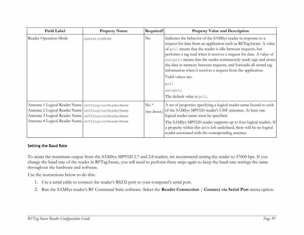
Reader Operation Mode operationMode No Indicates the behavior of the SAMSys reader in response to a request for data from an application such as RFTagAware. A value of poll means that the reader is idle between requests, but performs a tag read when it receives a request for data. A value of autopoll means that the reader continuously reads tags and stores the data in memory between requests, and forwards all stored tag information when it receives a request from the application. Valid values are: poll autopoll The default value is poll.
Antenna 1 Logical Reader Name Antenna 2 Logical Reader Name Antenna 3 Logical Reader Name Antenna 4 Logical Reader Name
uhf1LogicalReaderName uhf2LogicalReaderName uhf3LogicalReaderName uhf4LogicalReaderName
No * (see descr.)
A set of properties specifying a logical reader name bound to each of the SAMSys MP9320 reader's UHF antennas. At least one logical reader name must be specified. The SAMSys MP9320 reader supports up to four logical readers. If a property within this set is left undefined, there will be no logical reader associated with the corresponding antenna.
Setting the Baud Rate
To attain the maximum output from the SAMSys MP9320 2.7 and 2.8 readers, we recommend setting the reader to 57600 bps. If you change the baud rate of the reader in RFTagAware, you will need to perform these steps again to keep the baud rate settings the same throughout the hardware and software. Use the instructions below to do this:
1. Use a serial cable to connect the reader’s RS232 port to your computer's serial port. 2. Run the SAMSys reader’s RF Command Suite software. Select the Reader Connection | Connect via Serial Port menu option.

Page 40 RFTagAware Reader Configuration Guide
3. The software should detect the reader connected to your computer’s serial port. If you cannot establish a connection, select the menu item Reader Connection | Serial Port Settings, and use the Maximum Speed field to set the correct baud rate to connect to the reader.
4. Open a web browser and navigate to http://<IP.address.of.reader>/ . This URL will launch a Java applet. You will need to enable Java in your web browser to see the applet. If you would prefer to perform this configuration via telnet, skip step 5 and follow the instructions in Appendix C of the MP9320 2.7 User’s Guide.
5. On the applet that displays, click Serial Ports on the left side of the page, change the Baud Rate to 57600, then click Save. 6. In the RF Command Suite software, click the Command tab, and type the command }Cw,d:scw,b:00161616,f:1! to set the
reader's baud rate to 57600. 7. Close the RF Command Suite and the web browser window. 8. Power-cycle the reader. Afterward, the reader's external RS232 port and the external serial port on the Digi Connect ME Module
are set to a baud rate of 57600. Notes: If the reader stops responding, use HyperTerminal to connect to the reader, power-cycle it, and press the [Enter] key three
times. This will set the reader to the factory default.
MP9210
The SAMSys MP9210 reader driver requires the use of a MOXA serial-to-Ethernet adapter. This reader uses the following properties:
Field Label Property Name Required? Property Value and Description
Device Type class Yes Must be set to: com.connecterra.ale.readertypes. SAMSysMP9210PhysicalReader
Reader Hostname hostname Yes The DNS name or IP address of the MOXA serial-to-Ethernet adapter to which the reader is connected.
Reader Port port No The TCP port the Edge Server will use when establishing connections to the MOXA serial-to-Ethernet adapter. The default value is 4001.
RFTagAware Reader Configuration Guide Page 41
Field Label Property Name Required? Property Value and Description
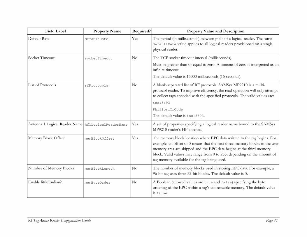
Default Rate defaultRate Yes The period (in milliseconds) between polls of a logical reader. The same defaultRate value applies to all logical readers provisioned on a single physical reader.
Socket Timeout socketTimeout No The TCP socket timeout interval (milliseconds). Must be greater than or equal to zero. A timeout of zero is interpreted as an infinite timeout. The default value is 15000 milliseconds (15 seconds).
List of Protocols rfProtocols No A blank-separated list of RF protocols. SAMSys MP9210 is a multi-protocol reader. To improve efficiency, the read operation will only attempt to collect tags encoded with the specified protocols. The valid values are: iso15693 Philips_I_Code The default value is iso15693.
Antenna 1 Logical Reader Name hf1LogicalReaderName Yes A set of properties specifying a logical reader name bound to the SAMSys MP9210 reader's HF antenna.
Memory Block Offset memBlockOffset Yes The memory block location where EPC data written to the tag begins. For example, an offset of 3 means that the first three memory blocks in the user memory area are skipped and the EPC data begins at the third memory block. Valid values may range from 0 to 255, depending on the amount of tag memory available for the tag being used.
Number of Memory Blocks memBlockLength No The number of memory blocks used in storing EPC data. For example, a 96-bit tag uses three 32-bit blocks. The default value is 3.
Enable littleEndian? memByteOrder No A Boolean (allowed values are true and false) specifying the byte ordering of the EPC within a tag's addressable memory. The default value is false.

Page 42 RFTagAware Reader Configuration Guide
MP9210 Notes: 1. The reader will be connected to an IP network with MOXA serial server. 2. The serial configuration is shown below. If the reader’s serial configuration is changed, these settings should be adjusted
accordingly.
Baud rate: 9600 Parity: None Data bits: 8 Stop bit: 1 Flow control: None UART FIFO: Disable Interface: RS-232
3. A null modem is required if using a straight serial cable (DB9, female-to-male).
RFTagAware Reader Configuration Guide Page 43
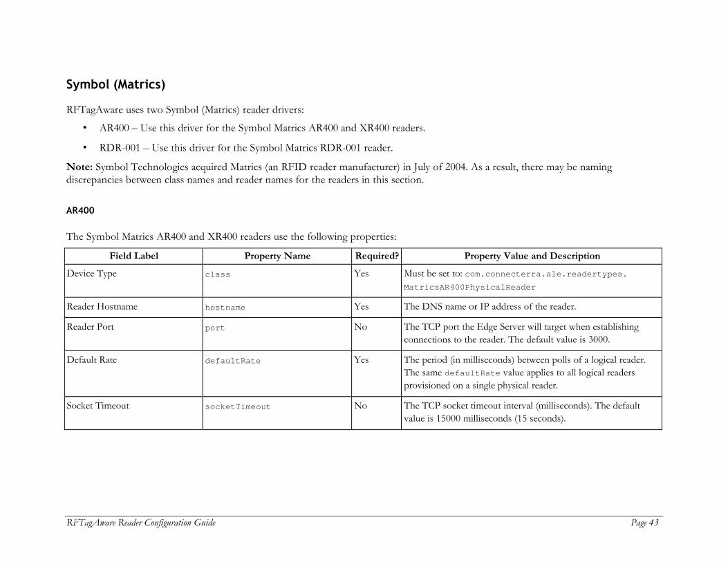
Symbol (Matrics)
RFTagAware uses two Symbol (Matrics) reader drivers:
• AR400 – Use this driver for the Symbol Matrics AR400 and XR400 readers.
• RDR-001 – Use this driver for the Symbol Matrics RDR-001 reader.
Note: Symbol Technologies acquired Matrics (an RFID reader manufacturer) in July of 2004. As a result, there may be naming discrepancies between class names and reader names for the readers in this section.
AR400
The Symbol Matrics AR400 and XR400 readers use the following properties:
Field Label Property Name Required? Property Value and Description
Device Type class Yes Must be set to: com.connecterra.ale.readertypes. MatricsAR400PhysicalReader
Reader Hostname hostname Yes The DNS name or IP address of the reader.
Reader Port port No The TCP port the Edge Server will target when establishing connections to the reader. The default value is 3000.
Default Rate defaultRate Yes The period (in milliseconds) between polls of a logical reader. The same defaultRate value applies to all logical readers provisioned on a single physical reader.
Socket Timeout socketTimeout No The TCP socket timeout interval (milliseconds). The default value is 15000 milliseconds (15 seconds).
Page 44 RFTagAware Reader Configuration Guide
Field Label Property Name Required? Property Value and Description
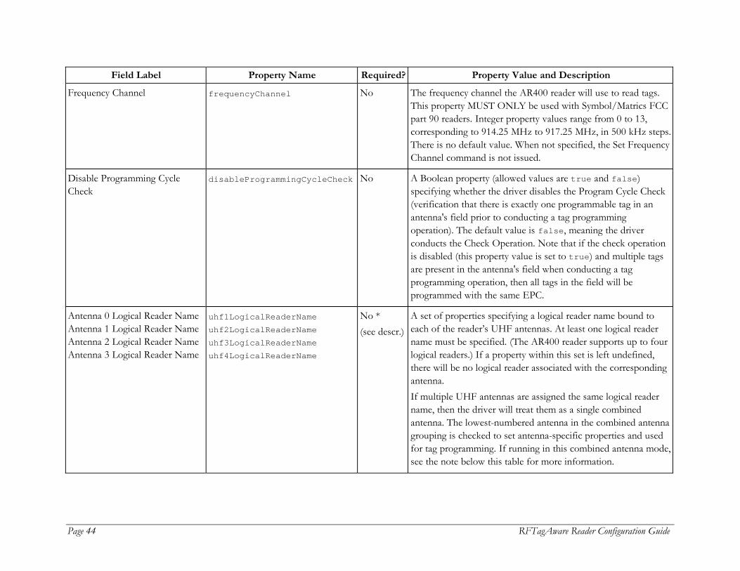
Frequency Channel frequencyChannel No The frequency channel the AR400 reader will use to read tags. This property MUST ONLY be used with Symbol/Matrics FCC part 90 readers. Integer property values range from 0 to 13, corresponding to 914.25 MHz to 917.25 MHz, in 500 kHz steps. There is no default value. When not specified, the Set Frequency Channel command is not issued.
Disable Programming Cycle Check
disableProgrammingCycleCheck No A Boolean property (allowed values are true and false) specifying whether the driver disables the Program Cycle Check (verification that there is exactly one programmable tag in an antenna's field prior to conducting a tag programming operation). The default value is false, meaning the driver conducts the Check Operation. Note that if the check operation is disabled (this property value is set to true) and multiple tags are present in the antenna's field when conducting a tag programming operation, then all tags in the field will be programmed with the same EPC.
Antenna 0 Logical Reader Name Antenna 1 Logical Reader Name Antenna 2 Logical Reader Name Antenna 3 Logical Reader Name
uhf1LogicalReaderName uhf2LogicalReaderName uhf3LogicalReaderName uhf4LogicalReaderName
No * (see descr.)
A set of properties specifying a logical reader name bound to each of the reader’s UHF antennas. At least one logical reader name must be specified. (The AR400 reader supports up to four logical readers.) If a property within this set is left undefined, there will be no logical reader associated with the corresponding antenna. If multiple UHF antennas are assigned the same logical reader name, then the driver will treat them as a single combined antenna. The lowest-numbered antenna in the combined antenna grouping is checked to set antenna-specific properties and used for tag programming. If running in this combined antenna mode, see the note below this table for more information.
RFTagAware Reader Configuration Guide Page 45
Field Label Property Name Required? Property Value and Description
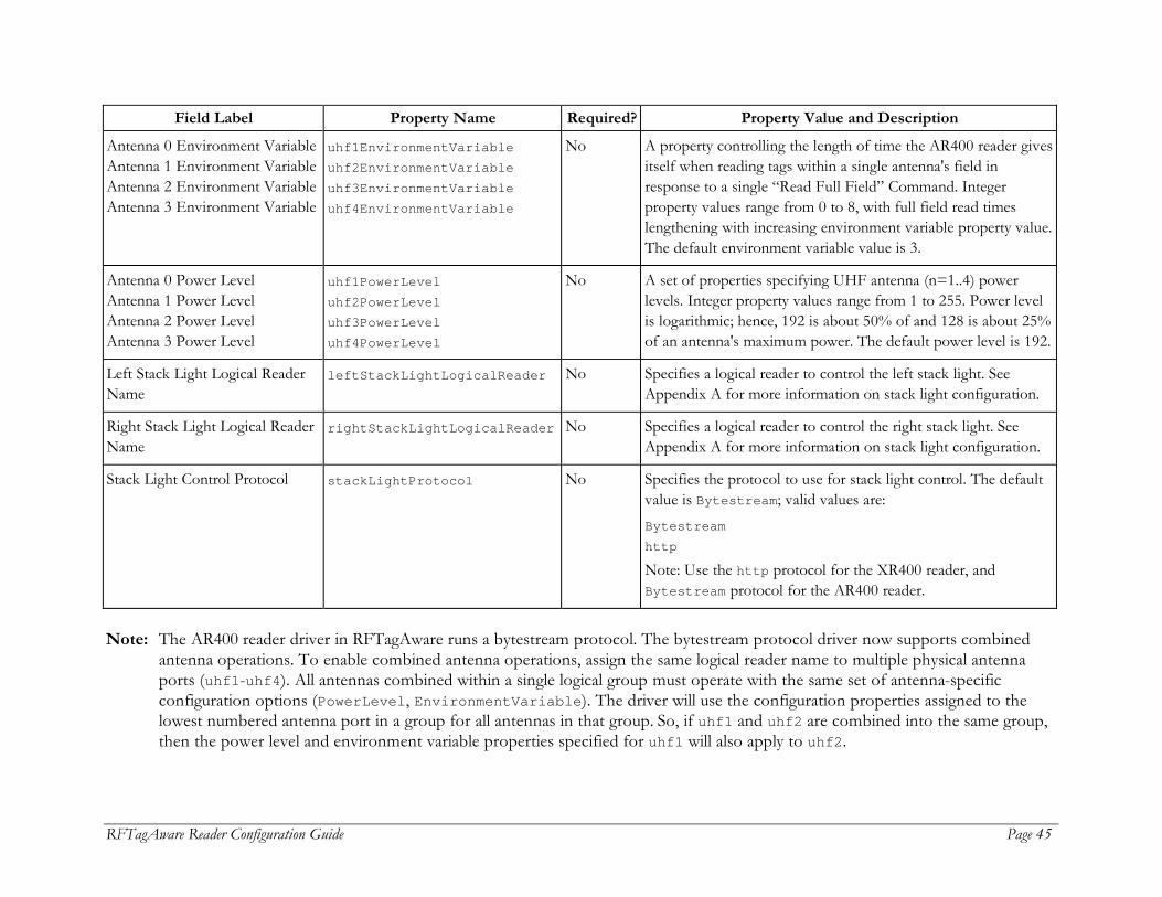
Antenna 0 Environment Variable Antenna 1 Environment Variable Antenna 2 Environment Variable Antenna 3 Environment Variable
uhf1EnvironmentVariable uhf2EnvironmentVariable uhf3EnvironmentVariable uhf4EnvironmentVariable
No A property controlling the length of time the AR400 reader gives itself when reading tags within a single antenna's field in response to a single “Read Full Field” Command. Integer property values range from 0 to 8, with full field read times lengthening with increasing environment variable property value. The default environment variable value is 3.
Antenna 0 Power Level Antenna 1 Power Level Antenna 2 Power Level Antenna 3 Power Level
uhf1PowerLevel uhf2PowerLevel uhf3PowerLevel uhf4PowerLevel
No A set of properties specifying UHF antenna (n=1..4) power levels. Integer property values range from 1 to 255. Power level is logarithmic; hence, 192 is about 50% of and 128 is about 25% of an antenna's maximum power. The default power level is 192.
Left Stack Light Logical Reader Name
leftStackLightLogicalReader No Specifies a logical reader to control the left stack light. See Appendix A for more information on stack light configuration.
Right Stack Light Logical Reader Name
rightStackLightLogicalReader No Specifies a logical reader to control the right stack light. See Appendix A for more information on stack light configuration.
Stack Light Control Protocol stackLightProtocol No Specifies the protocol to use for stack light control. The default value is Bytestream; valid values are: Bytestream http Note: Use the http protocol for the XR400 reader, and Bytestream protocol for the AR400 reader.
Note: The AR400 reader driver in RFTagAware runs a bytestream protocol. The bytestream protocol driver now supports combined
antenna operations. To enable combined antenna operations, assign the same logical reader name to multiple physical antenna ports (uhf1-uhf4). All antennas combined within a single logical group must operate with the same set of antenna-specific configuration options (PowerLevel, EnvironmentVariable). The driver will use the configuration properties assigned to the lowest numbered antenna port in a group for all antennas in that group. So, if uhf1 and uhf2 are combined into the same group, then the power level and environment variable properties specified for uhf1 will also apply to uhf2.
Page 46 RFTagAware Reader Configuration Guide
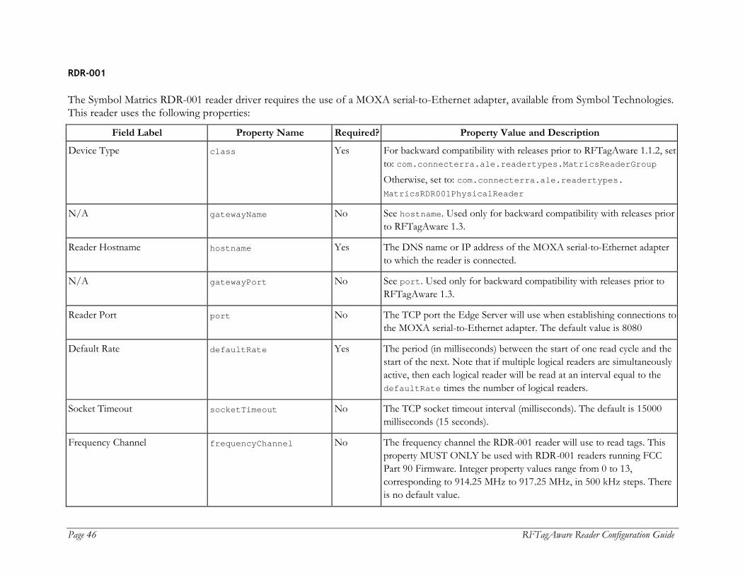
RDR-001
The Symbol Matrics RDR-001 reader driver requires the use of a MOXA serial-to-Ethernet adapter, available from Symbol Technologies. This reader uses the following properties:
Field Label Property Name Required? Property Value and Description
Device Type class Yes For backward compatibility with releases prior to RFTagAware 1.1.2, set to: com.connecterra.ale.readertypes.MatricsReaderGroup Otherwise, set to: com.connecterra.ale.readertypes. MatricsRDR001PhysicalReader
N/A gatewayName No See hostname. Used only for backward compatibility with releases prior to RFTagAware 1.3.
Reader Hostname hostname Yes The DNS name or IP address of the MOXA serial-to-Ethernet adapter to which the reader is connected.
N/A gatewayPort No See port. Used only for backward compatibility with releases prior to RFTagAware 1.3.
Reader Port port No The TCP port the Edge Server will use when establishing connections to the MOXA serial-to-Ethernet adapter. The default value is 8080
Default Rate defaultRate Yes The period (in milliseconds) between the start of one read cycle and the start of the next. Note that if multiple logical readers are simultaneously active, then each logical reader will be read at an interval equal to the defaultRate times the number of logical readers.
Socket Timeout socketTimeout No The TCP socket timeout interval (milliseconds). The default is 15000 milliseconds (15 seconds).
Frequency Channel frequencyChannel No The frequency channel the RDR-001 reader will use to read tags. This property MUST ONLY be used with RDR-001 readers running FCC Part 90 Firmware. Integer property values range from 0 to 13, corresponding to 914.25 MHz to 917.25 MHz, in 500 kHz steps. There is no default value.
RFTagAware Reader Configuration Guide Page 47
Field Label Property Name Required? Property Value and Description
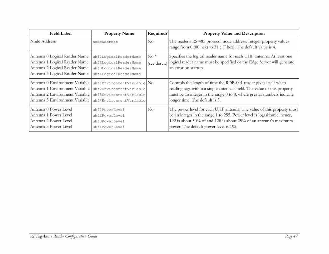
Node Address nodeAddress No The reader's RS-485 protocol node address. Integer property values range from 0 (00 hex) to 31 (1F hex). The default value is 4.
Antenna 0 Logical Reader Name Antenna 1 Logical Reader Name Antenna 2 Logical Reader Name Antenna 3 Logical Reader Name
uhf1LogicalReaderName uhf2LogicalReaderName uhf3LogicalReaderName uhf4LogicalReaderName
No * (see descr.)
Specifies the logical reader name for each UHF antenna. At least one logical reader name must be specified or the Edge Server will generate an error on startup.
Antenna 0 Environment Variable Antenna 1 Environment Variable Antenna 2 Environment Variable Antenna 3 Environment Variable
uhf1EnvironmentVariable uhf2EnvironmentVariable uhf3EnvironmentVariable uhf4EnvironmentVariable
No Controls the length of time the RDR-001 reader gives itself when reading tags within a single antenna's field. The value of this property must be an integer in the range 0 to 8, where greater numbers indicate longer time. The default is 3.
Antenna 0 Power Level Antenna 1 Power Level Antenna 2 Power Level Antenna 3 Power Level
uhf1PowerLevel uhf2PowerLevel uhf3PowerLevel uhf4PowerLevel
No The power level for each UHF antenna. The value of this property must be an integer in the range 1 to 255. Power level is logarithmic; hence, 192 is about 50% of and 128 is about 25% of an antenna's maximum power. The default power level is 192.

Page 48 RFTagAware Reader Configuration Guide
TAGSYS
This section describes driver configuration information for the TAGSYS Medio L100 and L200 RFID readers. The TAGSYS Medio L100 and L200 reader drivers require the use of a MOXA serial-to-Ethernet adapter, available from Symbol Technologies. These readers use the following properties:
Field Label Property Name Required? Property Value and Description
Device Type class Yes Must be set to: com.connecterra.ale.readertypes. TagsysLX00PhysicalReader
Reader Hostname hostname Yes The DNS name or IP address of the MOXA serial-to-Ethernet adapter to which the reader is connected.
Reader Port port No The TCP port the Edge Server will use when establishing connections to the MOXA serial-to-Ethernet adapter. The default value is 4001.
Socket Timeout socketTimeout No The TCP socket timeout interval (milliseconds). The default value is 15000 milliseconds (15 seconds).
Default Rate defaultRate Yes The period (in milliseconds) between polls of a logical reader. The same defaultRate value applies to all logical readers provisioned on a single physical reader.
RF Protocol rfProtocols No The RF protocol to use in tag acquisition. The TAGSYS is a multi-protocol reader. At least one protocol must be specified. Valid values are: Philips_I_Code iso15693 The default value is iso15693.
Memory Block Offset memBlockOffset Yes The memory block location where EPC data written to the tag begins. For example, an offset of 3 means that the first three memory blocks in the user memory area are skipped and the EPC data begins at the third memory block.

RFTagAware Reader Configuration Guide Page 49
Field Label Property Name Required? Property Value and Description
Number of Memory Blocks memBlockLength No The number of memory blocks used in storing EPC data. For example, a 96-bit tag uses three 32-bit blocks. The default value is 3.
Enable littleEndian? memByteOrder No A Boolean (allowed values are true and false) specifying the byte ordering of the EPC within a tag's addressable memory. The default value is false.
RF Power in mW rfPowerLevel No The RF power setting of the TAGSYS reader. The range of valid values is from 0 (minimum power) to 4000 (maximum power). The default value is 2000.
Ch. 1 Logical Reader Name Ch. 2 Logical Reader Name Ch. 3 Logical Reader Name Ch. 4 Logical Reader Name
hf1LogicalReaderName hf2LogicalReaderName hf3LogicalReaderName hf4LogicalReaderName
No Specifies the logical reader name for each HF antenna. At least one logical reader name must be specified or the Edge Server will generate an error on startup. Please note that the L100 reader has two antennas and the L200 reader has four antennas.
Notes:
1. The reader will be connected to an IP network with MOXA serial server. 2. The serial configuration is shown below. If the reader’s serial configuration is changed, adjust these settings accordingly.
Baud rate: 38400 Parity: None Data bits: 8 Stop bit: 1 Flow control: None UART FIFO: Disable Interface: RS-232
3. A null modem is required if using a cross serial cable (DB9, female-to-female).
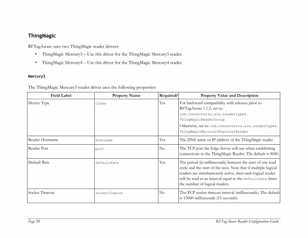
Page 50 RFTagAware Reader Configuration Guide
ThingMagic
RFTagAware uses two ThingMagic reader drivers:
• ThingMagic Mercury3 – Use this driver for the ThingMagic Mercury3 reader.
• ThingMagic Mercury4 – Use this driver for the ThingMagic Mercury4 reader.
Mercury3
The ThingMagic Mercury3 reader driver uses the following properties:
Field Label Property Name Required? Property Value and Description
Device Type class Yes For backward compatibility with releases prior to RFTagAware 1.1.2, set to: com.connecterra.ale.readertypes. ThingMagicReaderGroup Otherwise, set to: com.connecterra.ale.readertypes. ThingMagicMercury3PhysicalReader
Reader Hostname hostname Yes The DNS name or IP address of the ThingMagic reader
Reader Port port No The TCP port the Edge Server will use when establishing connections to the ThingMagic Reader. The default is 8080.
Default Rate defaultRate Yes The period (in milliseconds) between the start of one read cycle and the start of the next. Note that if multiple logical readers are simultaneously active, then each logical reader will be read at an interval equal to the defaultRate times the number of logical readers.
Socket Timeout socketTimeout No The TCP socket timeout interval (milliseconds). The default is 15000 milliseconds (15 seconds).

RFTagAware Reader Configuration Guide Page 51
Field Label Property Name Required? Property Value and Description
Read Timeout readTimeout No Specifies the maximum amount of time (in milliseconds) the reader may spend when servicing a request to read tags in a single antenna's field. The default value is 250 milliseconds.
Write Timeout writeTimeout No Specifies the maximum amount of time (in milliseconds) the reader may spend when servicing a request to program a tag across a single antenna. The default value is 250 milliseconds.
Disable Programming Cycle Check disableProgrammingCycleCheck No An optional Boolean property (allowed values are true and false) specifying whether the driver disables the “Check Operation” (verification that there is a single tag in an antenna's field prior to conducting a tag programming operation). The default value is false, meaning the driver conducts the Check Operation. Note that if the check operation is disabled (this property value is set to true) and multiple tags are present in the antenna's field when conducting a tag programming operation, then all tags in the field will be programmed with the same EPC.
UHF Antenna 1 Logical Reader Name UHF Antenna 2 Logical Reader Name
uhf1LogicalReaderName uhf2LogicalReaderName
No * (see descr.)
Specifies the logical reader name for each UHF (915 MHz) antenna. At least one logical reader name must be specified. If one of these properties is left undefined, there will be no logical reader associated with the corresponding antenna, and that antenna will not be accessible via the ALE API. If multiple UHF antennas are assigned the same logical reader name, then the driver will treat them as a single combined antenna. The lowest-numbered antenna in the combined antenna grouping is checked to set antenna-specific properties and used for tag programming.

Page 52 RFTagAware Reader Configuration Guide
Field Label Property Name Required? Property Value and Description
HF Antenna 1 Logical Reader Name HF Antenna 2 Logical Reader Name
hf1LogicalReaderName hf2LogicalReaderName
No * (see descr.)
Specifies the logical reader name for each HF (13.56 MHz) antenna. At least one logical reader name must be specified. If one of these properties is left undefined, there will be no logical reader associated with the corresponding antenna, and that antenna will not be accessible via the ALE API.
The ThingMagic reader obtains its IP network configuration dynamically via DHCP, or statically through one of the reader's configuration interfaces. Refer to the ThingMagic User Guide for further details.
Mercury4
The ThingMagic Mercury4 reader driver uses the following properties:
Field Label Property Name Required? Property Value and Description
Device Type class Yes Must be set to: com.connecterra.ale.readertypes. ThingMagicMercury4PhysicalReader
Reader Hostname hostname Yes The DNS name or IP address of the ThingMagic reader
Reader Port port No The TCP port the Edge Server will use when establishing connections to the ThingMagic Reader. The default is 8080.
Default Rate defaultRate Yes The period (in milliseconds) between the start of one read cycle and the start of the next. Note that if multiple logical readers are simultaneously active, then each logical reader will be read at an interval equal to the defaultRate times the number of logical readers.
Socket Timeout socketTimeout No The TCP socket timeout interval (milliseconds). The default is 15000 milliseconds (15 seconds).

RFTagAware Reader Configuration Guide Page 53
Field Label Property Name Required? Property Value and Description
Read Timeout readTimeout No Specifies the maximum amount of time (in milliseconds) the reader may spend when servicing a request to read tags in a single antenna's field. The default value is 250 milliseconds.
Write Timeout writeTimeout No Specifies the maximum amount of time (in milliseconds) the reader may spend when servicing a request to program a tag across a single antenna. The default value is 250 milliseconds.
Disable Programming Cycle Check disableProgrammingCycleCheck No An optional Boolean property (allowed values are true and false) specifying whether the driver disables the “Check Operation” (verification that there is a single tag in an antenna's field prior to conducting a tag programming operation). The default value is false, meaning the driver conducts the Check Operation. Note that if the check operation is disabled (this property value is set to true) and multiple tags are present in the antenna's field when conducting a tag programming operation, then all tags in the field will be programmed with the same EPC.
UHF Antenna 1 Logical Reader Name UHF Antenna 2 Logical Reader Name UHF Antenna 3 Logical Reader Name ... UHF Antenna 16 Logical Reader Name
uhf1LogicalReaderName uhf2LogicalReaderName uhf3LogicalReaderName ... uhf16LogicalReaderName
No * (see descr.)
Specifies the logical reader name for each UHF (915 MHz) antenna. At least one logical reader name must be specified. If one of these properties is left undefined, there will be no logical reader associated with that antenna, and that antenna will not be accessible via the ALE API. If multiple UHF antennas are assigned the same logical reader name, then the driver will treat them as a single combined antenna. The lowest-numbered antenna in the combined antenna grouping is checked to set antenna-specific properties and used for tag programming.

Page 54 RFTagAware Reader Configuration Guide
Field Label Property Name Required? Property Value and Description
HF Antenna 1 Logical Reader Name HF Antenna 2 Logical Reader Name HF Antenna 3 Logical Reader Name HF Antenna 4 Logical Reader Name
hf1LogicalReaderName hf2LogicalReaderName hf3LogicalReaderName hf4LogicalReaderName
No * (see descr.)
Specifies the logical reader name for each HF (13.56 MHz) antenna. At least one logical reader name must be specified. If one of these properties is left undefined, there will be no logical reader associated with that antenna, and that antenna will not be accessible via the ALE API.
N/A rfProtocol No See rfProtocols. Used only for backward compatibility with releases prior to RFTagAware 1.3.
List of Protocols rfProtocols No A blank-separated list of RF protocols. Mercury4 is a multi-protocol reader and can operate in read-only or read-write mode. At least one protocol must be specified. At present, the valid values are: epcClass0 (read-only, reads EPC Class 0 and Class 0+ tags) epcClass1 (read-write, reads/writes EPC Class 1 tags only) ALL (read-write, reads EPC Class 0, Class 0+, and Class 1 tags, writes Class 1 tags) The default value is epcClass1.
The ThingMagic reader obtains its IP network configuration dynamically via DHCP, or statically through one of the reader's configuration interfaces. Refer to the ThingMagic User Guide for further details.

RFTagAware Reader Configuration Guide Page 55
Zebra
This section describes driver configuration information for the Zebra R110XiIIIPlus, R110Xi and R4MPlus label printers.
• The R110XiIIIPlus printer supports the writing (programming) of Class 0+ and Class 1 tags embedded within label stock (“smart labels”) and the printing of those labels.
• The R110Xi printer supports the writing and printing of Class 0+ and Class 1 tags embedded within label stock (“smart labels”).
• The R4MPlus printer does the same for Class 1 tags.
The Zebra R110XiIIIPlus, R110Xi and R4MPlus printer drivers share all the same properties except class, as shown in the following table.
Field Label Property Name Required? Property Value and Description
Device Type class Yes R110XiIIIPlus: com.connecterra.ale.readertypes. ZebraR110XiIIIPlusPhysicalReader R110Xi: com.connecterra.ale.readertypes. ZebraR110XiIIIPlusPhysicalReader R4MPlus: com.connecterra.ale.readertypes.ZebraR4MPlusPhysicalReader
Reader Hostname hostname Yes The DNS name or IP address of the printer’s LAN adapter.
Reader Port port No The TCP port the Edge Server will target when establishing connections to the printer’s LAN adapter. The default value is 9100, the Zebra R110XiIIIPlus device’s factory default.
Socket Timeout socketTimeout No The TCP socket timeout interval (milliseconds). The default value is 15000 milliseconds (15 seconds).
Logical Reader Name uhf1LogicalReaderName Yes The logical reader name assigned to the Zebra device’s single integrated UHF antenna.
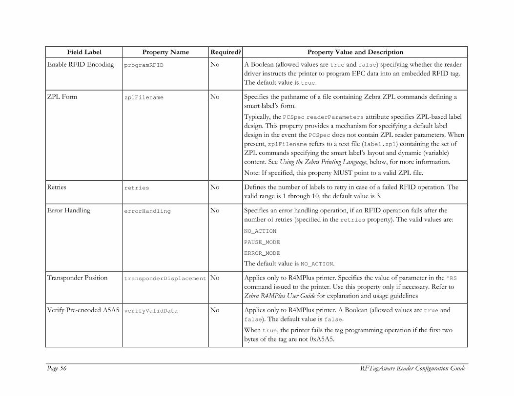
Page 56 RFTagAware Reader Configuration Guide
Field Label Property Name Required? Property Value and Description
Enable RFID Encoding programRFID No A Boolean (allowed values are true and false) specifying whether the reader driver instructs the printer to program EPC data into an embedded RFID tag. The default value is true.
ZPL Form zplFilename No Specifies the pathname of a file containing Zebra ZPL commands defining a smart label’s form. Typically, the PCSpec readerParameters attribute specifies ZPL-based label design. This property provides a mechanism for specifying a default label design in the event the PCSpec does not contain ZPL reader parameters. When present, zplFilename refers to a text file (label.zpl) containing the set of ZPL commands specifying the smart label’s layout and dynamic (variable) content. See Using the Zebra Printing Language, below, for more information. Note: If specified, this property MUST point to a valid ZPL file.
Retries retries No Defines the number of labels to retry in case of a failed RFID operation. The valid range is 1 through 10, the default value is 3.
Error Handling errorHandling No Specifies an error handling operation, if an RFID operation fails after the number of retries (specified in the retries property). The valid values are: NO_ACTION PAUSE_MODE ERROR_MODE The default value is NO_ACTION.
Transponder Position transponderDisplacement No Applies only to R4MPlus printer. Specifies the value of parameter in the ^RS command issued to the printer. Use this property only if necessary. Refer to Zebra R4MPlus User Guide for explanation and usage guidelines
Verify Pre-encoded A5A5 verifyValidData No Applies only to R4MPlus printer. A Boolean (allowed values are true and false). The default value is false. When true, the printer fails the tag programming operation if the first two bytes of the tag are not 0xA5A5.

RFTagAware Reader Configuration Guide Page 57
Using the Zebra Printing Language (ZPL II)
ZPL is a scripting language for specifying the layout and contents of printed labels. ZPL is described in detail in the Zebra document, ZPLII Programming Guide (Zebra Document 45541LB-R3). The Zebra printer driver sends its printer a separate collection of ZPL commands with each “smart label” (a printed label with an embedded RFID tag) to be printed and programmed. Users specify a smart label’s ZPL commands when defining a PCSpec (see the RFTagAware Programmer Guide). A PCSpec’s readerParameters field carries the ZPL script as a String object; the corresponding reader parameter name is zplScript. (For backward compatibility with releases prior to RFTagAware 1.3, use the reader parameter name com.connecterra.ale.readertypes.ZebraR110XiIIIPlus.zplScript. This parameter name applies when using the Zebra R4MPlus printer as well as the R110XiIIIPlus.) As an alternative to specifying ZPL within a PCSpec, the Edge Server administrator may specify a default ZPL script using the Zebra reader driver’s zplFilename property. The zplFilename property provides a mechanism for specifying ZPL commands that serve as a default label design in the event the PCSpec’s readerParameters field does not carry a key/value pair containing a ZPL script. Below is a sample ZPL script (blank lines have been inserted for readability): ^XA ^FX *** NOTE: Lines, beginning with ^FX are comments ***^FS ^FX Set home position ^FS ^LH30,35 ^FX Write EPC HEX ^FS ^WT,,,,1^FD[EPC_HEX]^FS ^FX "Ship From" text ^FS ^FO20,15^A0N,18,,^FDSHIP FROM:^FS ^FO20,40^A0N,26,,^FDAcme^FS ^FO20,65^A0N,26,,^FDCorporation^FS ^FO20,90^A0N,26,,^FDP.O. Box 61900^FS ^FO20,115^A0N,26,,^FDDallas, TX 75261^FS ^FX Draw vertical line ^FS ^FO300,0^GB0,180,2^FS

Page 58 RFTagAware Reader Configuration Guide
^FX "Ship to" text ^FS ^FO320,15^A0N,18,,^FDSHIP TO:^FS ^FO320,40^A0N,26,,^FDRetailer Distribution Center^FS ^FO320,65^A0N,26,,^FD200 Main Street^FS ^FO320,90^A0N,26,,^FDSpringfield, MA01103^FS ^FX Draw horizontal line ^FS ^FO0,180^GB720,0,4^FS ^FX Postal code text ^FS ^FO20,195^A0N,18,,^FDSHIP TO POSTAL CODE:^FS ^FO30,275^A0N,32,,^BC,90,,Y,^FD(420) 01103^FS ^FX Draw vertical line ^FS ^FO340,180^GB0,270,2^FS ^FX Carrier text ^FS ^FO360,195^A0N,18,,^FDCARRIER:^FS ^FO360,245^A0N,36,,^FDAcme Freightways^FS ^FO360,295^A0N,30,,^FDPRO: 1234^FS ^FO360,345^A0N,30,,^FDB/L: 5678^FS ^FX Draw horizontal line ^FS ^FO0,450^GB720,0,4^FS ^FX EPC text ^FS ^FO0,465^A0N,32,,^FDEPC:^FS ^FO20,575^A0N,32,,^FD[EPC_TAG_URI]^FS ^FX Draw horizontal line ^FS ^FO0,670^GB720,0,4^FS

RFTagAware Reader Configuration Guide Page 59
^FX SKU text ^FS ^FO0,685^A0N,32,,^FDSKU:^FS ^FO15,724^A0N,36,,^FDABC21270^FS ^FX Draw hoarizontal line ^FS ^FO0,785^GB720,0,4^FS ^FX GTIN text ^FS ^FO0,800^A0N,32,,^FDGTIN^FS ^FO100,890^A0N,32,,^BC,90,,Y,^FD>; (01) 10036000212706 ^FS ^XZ If the user wishes to print a specified EPC value on the smart label, the user-supplied ZPL must include special substitution strings, indicating in what representation the tag values are to be printed. RFTagAware recognizes the following substitution string values:
[EPC_HEX] Will be replaced by the hexadecimal representation of the tag value.
[EPC_ID_URI] Will be replaced by the pure identity URN representation of the tag value.
[EPC_TAG_URI] Will be replaced by the tag URN representation of the tag value.
Example: ^XA ^FO20,575^A0N,32,,^FD[EPC_TAG_URI]^FS ^XZ
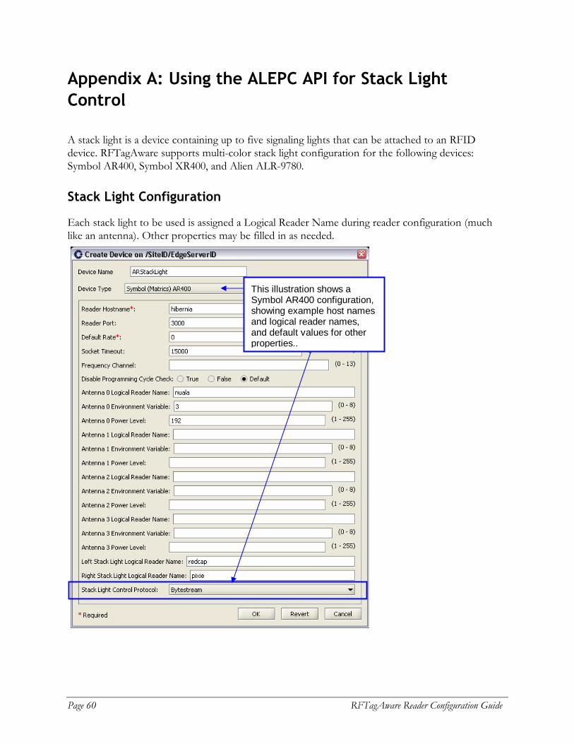
Page 60 RFTagAware Reader Configuration Guide
Appendix A: Using the ALEPC API for Stack Light Control
A stack light is a device containing up to five signaling lights that can be attached to an RFID device. RFTagAware supports multi-color stack light configuration for the following devices: Symbol AR400, Symbol XR400, and Alien ALR-9780.
Stack Light Configuration
Each stack light to be used is assigned a Logical Reader Name during reader configuration (much like an antenna). Other properties may be filled in as needed.
This illustration shows a Symbol AR400 configuration, showing example host names and logical reader names, and default values for other properties..
RFTagAware Reader Configuration Guide Page 61
Stack Light Control
Stack light control is accomplished by writing a special EPC value to the logical reader representing a stack light. The EPC is represented by the URI: urn:connecterra:stacklight:update=<update value> The update value consists of five hexadecimal digits. Each digit sets the display on one of the five supported colors (from most significant to least significant): White, Blue, Green, Amber, and Red. Each digit can be one of the following values: • 0 = turns the color off • 1-8 = turns the color on for 5 seconds times the value shown • 9 = turns the color on indefinitely, until a different value is written • F = does not change the current state Values of A-E are reserved for future use. If the update value written to the logical reader has more than five digits, the rightmost five digits are read to set the stack light colors (e.g., 88880000 is read as 80000). If the update value has less than five digits, the number is padded with zeroes on the left before the value is sent to the logical reader (e.g., FF0 is read as 00FF0). Example Value: A URI of urn:connecterra:stacklight:update=092F0 written to a stack light configured as described above will perform the following actions on the stack light: • 0 – turns off the White light • 9 – turns on the Blue light indefinitely, until next update • 2 – turns on the Green light for 10 seconds • F – leaves the Amber light unchanged • 0 – turns off the Red light Example API call: An example of an API call would look like this:
// This is a code fragment ALEPC alePCClient = new AxisALEPCClient(<ALEPC Service URL>); ALEPCFactory alePCFactory = AxisALEPCFactory.getInstance(); PCSpec pcSpec = alePCFactory.createPCSpec(); pcSpec.addLogicalReaderName(“LSL”); alePCClient.immediate( pcSpec, new URI(“urn:connecterra:stacklight:update=092F0”));

Page 62 RFTagAware Reader Configuration Guide
Appendix B: Controlling RFID Devices Using PLCs
RFTagAware allows you to receive information about other devices and control them, by communicating with a programmable logic controller (PLC), which is a specialized industrial computer used for automation of real-world processes. A programmable logic controller has a number of registers, which are used to hold information. Registers are sometimes referred to as items or tags (not to be confused with EPC tags). Applications interacting with the PLC can either:
• read the contents of one or more registers (referred to as inbound messages) and take action based on the value(s) read, or
• write information to one or more registers to make it available to other applications (referred to as outbound messages).
Configuring RFTagAware to enable PLC communications requires adding the following items to RFTA-HOME\etc\edge.props:
• One or more transports, which specify the underlying mechanism used to send messages and the location to which messages should be sent. There may be other configuration options specific to the transport chosen. The available implementations are OPC_XML, StarThis, and ModBus.
• One or more message conventions, which must correspond to the conventions expected by the PLC that RFTagAware communicates with. The conventions supported are Simple and CounterPair. Multiple messages can use the same message convention.
• One or more messages, which specify the tag(s) or item(s) on the PLC to read from or write to, and the value(s) to be written. The same message can be sent for multiple events. The messages supported are inboundMessage and outboundMessage.
In general, customers that would like to enable their installation of RFTagAware to control RFID devices using programmable logic controllers will need some custom development effort. The instructions provided below illustrate one possible configuration of RFTagAware after custom development work has been completed. Please contact your account representative if you would like more information on customization options.
Note: All property names shown in this section should be prefixed with com.connecterra.ale.plc, which is abbreviated [CCAP] in the properties below.
1. Create a backup copy of RFTA-HOME\etc\edge.props and open the original for editing. 2. Define a transport to be used for PLC communications. The supported implementations
are OPC_XML, StarThis, and ModBus. # ModBus configuration [CCAP].plcTransport.modbus1.metaName = ModBus [CCAP].plcTransport.modbus1.hostname = 10.40.10.157 [CCAP].plcTransport.modbus1.socketTimeout = 10000 [CCAP].plcTransport.modbus1.pollInterval = 500
RFTagAware Reader Configuration Guide Page 63
# OPC_XML configuration [CCAP].plcTransport.opcABC.metaName = OPC_XML [CCAP].plcTransport.opcABC.hostname = http://plchost/path # StarThis configuration [CCAP].plcTransport.ab1756.metaName = StarThis [CCAP].plcTransport.ab1756.licenseDir = ..\licenses [CCAP].plcTransport.ab1756.storageDir = ..\var\plc-storage [CCAP].plcTransport.ab1756.hostname = ab1756 [CCAP].plcTransport.ab1756.backplanePort = 0 [CCAP].plcTransport.ab1756.pollInterval = 50
3. Choose a message convention. The types supported are Simple and CounterPair. The notations <var1> and <var2> should be replaced by property names that you choose. # SimpleTransaction configuration [CCAP].plcMessageConvention.<var1>.metaName = Simple # The plcTransport name shown below should be a hostname from step 2. [CCAP].plcMessageConvention.<var1>.plcTransport = ab1756 # CounterPairTransaction configuration [CCAP].plcMessageConvention.<var2>.metaName = CounterPair # The plcTransport name shown below should be a hostname from step 2. [CCAP].plcMessageConvention.<var2>.plcTransport = ab1756 [CCAP].plcMessageConvention.<var2>.restart.receiveCounterItem = PLCRestart[2] [CCAP].plcMessageConvention.<var2>.restart.ackCounterItem = PLCRestartAck[2] [CCAP].plcMessageConvention.<var2>.restart.dataItems = PLCRestart[0] [CCAP].plcMessageConvention.<var2>.restart.prefetch = true # Configure the next two properties on ONE client only [CCAP].plcMessageConvention.<var2>.restartAckStatusItem = PLCRestartAck[0] [CCAP].plcMessageConvention.<var2>.restartDelay = 100 Note: The array elements shown above and in step 4 refer to PLC registers on the PLCs in
use at your organization. Both the register names and element numbers may differ from the sample information shown.
4. Define the inbound and outbound messages for the message convention chosen in the prior step. The notations <var1> and <var2> should be replaced by the property names you chose in step 3. # Simple inboundMessage configuration [CCAP].inboundMessage.doorOpen.plcMessageConvention = <var1> [CCAP].inboundMessage.doorOpen.receiveItem = D2052 [CCAP].inboundMessage.doorOpen.matchValues = true # CounterPair inboundMessage configuration [CCAP].inboundMessage.BCRArrival.plcMessageConvention = <var2> [CCAP].inboundMessage.BCRArrival.sendCounterItem = BCRArrival[19]

Page 64 RFTagAware Reader Configuration Guide
[CCAP].inboundMessage.BCRArrival.ackCounterItem = BCRArrivalAck[0] [CCAP].inboundMessage.BCRArrival.dataItems = BCRArrival # CounterPair outboundMessage configuration [CCAP].outboundMessage.SgtinAssign.plcMessageConvention = <var2> [CCAP].outboundMessage.SgtinAssign.sendCounterItem = SgtinAssign[59] [CCAP].outboundMessage.SgtinAssign.ackCounterItem = SGTINAssignAck[0] [CCAP].outboundMessage.SgtinAssign.dataItems = SgtinAssign
5. Save the changes to edge.props, and restart the Edge Server. 6. Configure your RFID devices to communicate with the PLC by defining devices as shown
below using the RFID Devices node on the Administration Console:
• Device Type: PLC-Connected Barcode Reader Logical Reader Name: <a reader name you choose> Inbound PLC Message Name: <the name of the inboundMessage carrying the bar code, e.g., BCRArrival in step 4>
• Device Type: PLC-Connected Label Print & Apply Logical Reader Name: <a reader name you choose> Outbound PLC Message Name: <the name of the outboundMessage, e.g., SgtinAssign in step 4>


![EID Reader Manual Installation Card Reader... · EID Reader Manual Installation [FAQ, Perquisite & Guides] Document Details EID Reader Manual Installation and Troubleshooting Software](https://img.dokumen.tips/doc/110x75/5e2b1bd34debb043f0778de5/eid-reader-manual-installation-card-reader-eid-reader-manual-installation-faq.jpg)