Embed Size (px)
Citation preview
RP
Frequency response (magnitide/phase) degradation
Interconnection network
ProbeCable
DP
DUT
BWmod 100 MHz to 2000 MHz20 MHz
2 GHz 28 GHz fRF
0,10
0,05
0,00
–0,05
–0,10
–0,15
–0,20
–0,25
–0,30
–0,35
Freq
uenc
y re
spon
se in
dB
–1000 –800 –600 –400 –200 0 200 400 600 800 1000
RF frequency offset in MHz
2 GHz modulation bandwidth
350065001500018500
Appl
icat
ion
Card
| Ve
rsio
n 01
.00
RF/m
icro
wav
e DU
T de
embe
ddin
g
RF/microwave DUT deembedding
Your taskLike most RF test instruments, an RF/microwave vector signal generator (VSG) is calibrated at its coaxial RF/mi-crowave interface, which is defined as the reference plane (RP). This means all VSG performance parameters(e.g. level uncertainty, frequency response flatness,etc.) are specified for this interface.
However, the device under test (DUT) is often not con-nected directly to this coaxial VSG interface but via an ac-tive/passive two-port interconnection network consisting of cables, attenuators, amplifiers, switches, test fixtures or even antennas.
Especially in the case of wideband microwave signals, a significant degradation of the frequency response flatness (magnitude/phase) can be observed at the DUT plane (DP) where the DUT is attached to the interconnection network.
Its excellent realtime baseband performance in combination with its ability to easily import the scattering parameters of an active/passive two-port interconnection network via s2p-files make the R&S®SMW200A vector signal generator ideal for high-precision RF and microwave tests requiring deembedding of the device under test (DUT).
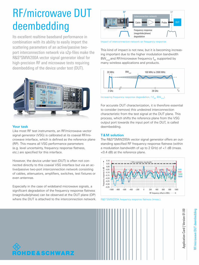
Impact of interconnection network on frequency response.
Increasing frequency response degradation, f (fRF, BWmod).
R&S®SMW200A frequency response flatness (meas.).
This kind of impact is not new, but it is becoming increas-ing important due to the higher modulation bandwidth BWmod and RF/microwave frequency fRF supported by many wireless applications and products.
For accurate DUT characterization, it is therefore essential to consider (remove) this undesired interconnection characteristic from the test signal at the DUT plane. This process, which shifts the reference plane from the VSG output port towards the input port of the DUT, is called deembedding.
T & M solutionThe R&S®SMW200A vector signal generator offers an out-standing specified RF frequency response flatness (within a modulation bandwidth of up to 2 GHz) of <1 dB (meas. <0.4 dB) at the reference plane.
RF-Microwave DUT_ac_en_5215-4469-92_v0100.indd 1 10.10.2017 15:57:27

Frequency response (magnitide/phase) degradation
Interconnection network
ProbeCable
RP
DUT
S2P-File
17500 17700 17900 18100 18300 18500 18700 18900 19100 19300 19500
0,5
0,0
–0,5
–1,0
–1,5
–2,0
–2,5
–3,0
–3,5
–4,0
RF frequency in MHz
Freq
uenc
y re
spon
se in
dB
2 GHz modulation bandwidth 2.86 dB abs. level corrrection
SVal. S + I
IS + I
Rohde & Schwarz GmbH & Co. KG
Europe, Africa, Middle East | +49 89 4129 12345
North America | 1 888 TEST RSA (1 888 837 87 72)
Latin America | +1 410 910 79 88
Asia Pacific | +65 65 13 04 88
China | +86 800 810 82 28 | +86 400 650 58 96
www.rohde-schwarz.com
R&S® is a registered trademark of Rohde & Schwarz GmbH & Co. KG
Trade names are trademarks of the owners
PD 5215.4469.92 | Version 01.00 | October 2017 (fi)
RF/microwave DUT deembedding
Data without tolerance limits is not binding | Subject to change
© 2017 Rohde & Schwarz GmbH & Co. KG | 81671 Munich, Germany 5215
.446
9.92
01.
00 P
DP
1 e
n
5215446992
This high-end flatness performance makes the R&S®SMW the preferred signal source for all types of RF/microwave wideband test applications, e.g. LTE carrier aggrega-tion, Wi-Fi/WLAN, pre-5G, 5G, radar signals and many others. The R&S®SMW-K544 user-defined frequency re-sponse correction (UDFRC) feature transfers this intrinsic R&S®SMW frequency response flatness towards the DUT plane by shifting the test signal reference plane to the in-put port of the DUT. This process of DUT deembedding is performed directly on the R&S®SMW in realtime by im-porting Touchstone® s2p files that describe the transmis-sion and reflection performance of the two-port intercon-nection network by its scattering parameters Sxy.
R&S®SMW-K544 – DUT deembedding.
R&S®SMW-K544 – s2p file import.
R&S®SMW-K544 – absolute RF level correction.
R&S®SMW-K544 capabilities.
The enormous flexibility of the UDFRC means that up to 10 simultaneous s2p files characterizing different parts (cables, switches attenuators, amplifiers, antennas, etc.) of the interconnection network can be imported.
All imported s2p files can be individually activated/deacti-vated on the fly by the user. The R&S®SMW automatically concatenates all S-parameter matrices in the case of a cas-caded interconnection network (multi s2p file scenarios).It is essential to know that the frequency response correc-tion applies to: ❙ The entire frequency range covered by the imported s2p file(s) and not only a certain dedicated RF frequency
❙ Any baseband signal and not only a dedicated waveformThis high flexibility considerably simplifies the required deembedding process.
In addition to the frequency response correction within the modulation bandwidth, an absolute RF level correction based on the activated s2p file(s) is available.
R&S®SMW-K544 deembedding steps: ❙ Characterize the interconnection by using either a
■ Vector network analyzer (VNA): phase/magnitude ■ Power sensor (e.g. R&S®NRP series): magnitudedepends on the requirements of your test application
❙ Import the resulting scattering parameters Sxy to the R&S®SMW as s2p file(s)
❙ Activate UDFRC.
The following graph gives an impression of the UDFRC capabilities.
The blue trace (S) describes the exceptional frequency re-sponse flatness over 2 GHz modulation bandwidth at the RP. The situation at the interconnection output ( ripple ≈1.5 dB, insertion loss = 2.89 dB), at the DP, is highlighted by the dark-blue trace (S+I). With this frequency response mapped into a s2p file and activated in the R&S®SMW UDFRC (with applied absolute level correction), we end up in the green frequency response (Val. S+I) at the DUT input.
Key factsThe R&S®SMW200A vector signal generator equipped with the R&S®SMW-K544 option: ❙ Vector modulated (wideband) RF and microwave signals with outstanding frequency response flatness
❙ Import of s2p file(s) characterizing a two-port interconnection network
❙ Realtime DUT deembedding with optional absolute RF level correction
See alsowww.rohde-schwarz.com/product/SMW200A
RF-Microwave DUT_ac_en_5215-4469-92_v0100.indd 2 10.10.2017 15:57:29


![PVCPR11 Edital 3.5 GHz v03.ppt [Modo de Compatibilidade]...2011/06/09 · 35 MHz 35 MHz 10 MHz 10 MHz 10 MHz 10 MHz 10 MHz 10 MHz 3.400,00 MHz 3.600,00 MHz 10 MHz 35 MHz 10 MHz 10](https://img.dokumen.tips/doc/110x75/5f7286506e7f433bb4685297/pvcpr11-edital-35-ghz-v03ppt-modo-de-compatibilidade-20110609-35-mhz.jpg)


