Embed Size (px)
DESCRIPTION
IEEE TRANSACTIONS ON AUTOMATION SCIENCE AND ENGINEERING
Citation preview

IEEE TRANSACTIONS ON AUTOMATION SCIENCE AND ENGINEERING, VOL. 6, NO. 1, JANUARY 2009 33
RFIDSim—A Physical and Logical Layer SimulationEngine for Passive RFID
Christian Floerkemeier and Sanjay Sarma
Abstract—Radio-frequency identification (RFID) poses anumber of research challenges, such as interference mitigation,throughput optimization and security over the RF channel. Anumber of new approaches to address these issues have beenproposed recently, but due to the highly integrated nature ofpassive RFID tags, it is difficult to evaluate them in real-worldscenarios. In this paper, we present an RFID simulation engine,RFIDSim, which implements the ISO 18000-6C communicationprotocol and supports pathloss, fading, backscatter, capture, andtag mobility models. This paper also shows that our implemen-tation of RFIDSim that relies on a discrete event simulator canbe used to simulate large populations featuring thousands ofRFID tags. RFIDSim also simulates the deep fades that lead tofrequent power losses of the battery-less RFID tags by modelingthe multipath effects statistically.
Note to Practitioners—It is difficult to physically test and vali-date the effectiveness of novel approaches that improve the speed atwhich large RFID tag populations can be identified and/or addresssome of the privacy and security concerns associated with RFID.An accurate evaluation of each protocol concept ideally requires acustomized microchip and new reader firmware, which is prohibi-tively expensive in many cases. Board-level emulators are anothermethod for testing new ideas in RFID. However, it is difficult to em-ulate the power-up limitations of passive RFID tags with poweredcircuits. Furthermore, a variety of real-world scenarios must berecreated and tested to truly understand the performance of a newidea. Examples include reading hundreds of tagged cases in palletsbeing carried on a forklift, items moving at 2 m/s on a manufac-turing line, and items moving on a conveyor. RFIDSim provides awell-controlled test environment to compare different approacheswithout the need to deploy hundreds of RFID tags and move themconsecutively past an RFID reader in experiments. RFIDSim canbe used to compare and classify different ideas in a variety of use-scenarios and reduce the number of concepts which need to be pro-totyped. Due to the nature of the wireless channel, it is very chal-lenging to accurately predict the signal strength distribution in aparticular application environment. RFIDSim is not capable of de-termining the exact zone, where a tag will be identified in a par-ticular application. The objective of RFIDSim is to facilitate therelative comparison of different medium access protocols, trans-mission control strategies, settings in ISO 18000-6C, and privacyand security enhancements.
Index Terms—Automatic identification, interference, ISO18000-6C, radio-frequency identification (RFID), simulation.
Manuscript received May 29, 2007; revised November 15, 2007. First pub-lished December 02, 2008; current version published December 30, 2008. Thispaper was recommended for publication by Associate Editor P. Cole and EditorN. Viswanadham upon evaluation of the reviewers’ comments.
C. Floerkemeier is with the Auto-ID Laboratory, Massachusetts Institute ofTechnology, Cambridge, MA, 02139 USA (e-mail: [email protected]).
S. Sarma is with the Mechanical Engineering Department, Massachusetts In-stitute of Technology, Cambridge, MA, 02139 USA (e-mail: [email protected]).
Color versions of one or more of the figures in this paper are available onlineat http://ieeexplore.ieee.org.
Digital Object Identifier 10.1109/TASE.2008.2007929
I. INTRODUCTION
RADIO-BASED identification has become common ina variety of applications where it is necessary to auto-
matically identify objects which are not proximate. Examplesinclude keyless entry badges, pet tagging, and car immobilizers.More recently, radio-frequency identification (RFID) systemswith an increased range have begun to find greater use in supplychain management and industrial automation. In these domains,radio-based identification has shown itself to be a promisingtechnology to track movements of goods because it does notrequire proximity or line-of-sight alignment and RFID tagscan be identified from a distance of a few meters by the RFIDreader. Since the RFID tags can thus be identified without aperson scanning the object—unlike in the case of traditionalbar codes—industry observers expect significant labor savingsfrom the use of the technology.
The proliferation of RFID tags and readers also introducesa number of technical challenges, however. While traditionalapplications for radio-based identification, such as car immo-bilizers or pet tagging, usually involve no more than a singletag in the read range of a reader, and the readers themselvesare sparsely deployed, today’s RFID applications in the supplychain feature large and densely packed tag populations whichmust often be read by several closely deployed readers. This de-velopment results in the need to coordinate access to the sharedradio channel efficiently [1], [2]. Furthermore, the increasedrange of today’s tags raises privacy and security questions [3].
While a number of innovative ideas have been proposed to ad-dress these issues, it has proven difficult to physically test andvalidate their effectiveness. Because of power and cost limita-tions, the physical and logical layers in passive RFID tags tendto be highly coupled, and an accurate evaluation of each protocolconcept ideally requires a customized microchip and new readerfirmware. This is prohibitively expensive. Board-level emula-tors are another method for testing new ideas in RFID. How-ever, it is difficult to emulate the power-up limitations of pas-sive RFID tags with powered circuits. Furthermore, a varietyof real-world scenarios must be recreated and tested to reallyunderstand the performance of a new idea. Examples includereading hundreds of tagged cases in pallets being carried ona forklift, items moving at 2 m/s on a manufacturing line anditems moving on a conveyor. Physically recreating these sce-narios and prototyping enough emulators can also be difficultand expensive.
In this paper, we describe an RFID simulation environment,RFIDSim, which facilitates the evaluation of RFID protocolsin real-world applications (cf. Fig. 1) by simulating signalpropagation and RFID communication protocols. The simu-lation engine can be used to compare and classify different
1545-5955/$25.00 © 2008 IEEE
Authorized licensed use limited to: Imperial College London. Downloaded on June 07,2010 at 19:36:24 UTC from IEEE Xplore. Restrictions apply.

34 IEEE TRANSACTIONS ON AUTOMATION SCIENCE AND ENGINEERING, VOL. 6, NO. 1, JANUARY 2009
Fig. 1. RFIDSim simulation scenario representing a typical RFID warehouseapplication.
ideas in a variety of use-scenarios and reduce the number ofconcepts which need to be prototyped. While wireless networksimulators have been built for other applications like cellulartelephony and ad hoc wireless networks, the needs of passiveRFID are unique. Since passive tags draw power from theelectromagnetic field generated by the RFID reader, the powerconsumed by the RFID tag chip has a significant impact onthe range and viability of a protocol. Furthermore, since tagstypically move a great deal, and since the reading action isrelatively rapid, the needs of a simulator are different fromother systems involving longer, “more stable” sessions. Typicalwarehouse applications also feature thousands of RFID tagsand multiple RFID readers, which require a scalable simulationengine. To meet these needs, RFIDSim supports differentpathloss, fading, backscatter, capture, and tag mobility modelsat the physical level and implements the ISO 18000-6C UHFRFID communication protocol (also known as EPCglobalGen2). While RFIDSim does not allow users to accuratelypredict the actual identification performance in a specificlocation due to the nature of the wireless channel, RFIDSimfacilitates the relative comparison of different transmissioncontrol strategies, settings in ISO 18000-6C and privacy andsecurity approaches. RFIDSim allows researchers to implementnew algorithms virtually on the tags and readers and to simulatetheir performance under different use-scenarios like at the dockdoor of a warehouse, on conveyors, etc.
This paper is organized as follows. In Section II, we presentrelated work. Sections III and IV present an overview of ISO18000-6C and RFIDSim, respectively. Section V illustratesthe simulation models used in RFIDSim and Section VIdiscusses how these models are implemented. Section VIIpresents RFIDSim simulation results and compares themto ISO 18000-6C. Section VIII discusses the limitations ofRFIDSim and future work, before we conclude in Section IX.
II. RELATED WORK
A number of other wireless network simulators have been de-
veloped in the past. Ns2 [4] has a long history in networking re-
search and features models for node mobility and wireless pro-
tocols. There is also GloMoSim [5] written in Parsec [6] which
has been extensively used in the ad hoc networking community.
These wireless simulators have been used successfully to study
routing and topology control schemes and also feature phys-
ical layer models for pathloss and fading. However, there are no
implementations of any RFID communication protocols, RFID
readers and tags and RFID physical layer characteristics avail-
able, such as the remote power supply to the passive RFID tags
or the backscatter mechanism.
To implement the ISO 18000-6C RFID protocol and the RFID
physical layer in RFIDSim, we use the discrete event simulator
JiST developed by Barr [7]. We also rely on the pathloss and
Rician-fading models provided by SWANS [8] which builds on
JiST. We chose to use the JiST/SWANS environment over Glo-
MoSim/Parsec and Ns2 because JiST combines ease of software
development with high performance [9].
There has also been related work by other researchers in the
RFID domain on the simulation of RFID systems. Han et al.
[10] developed a system model of UHF RFID with a strong
focus on the RF/analog design of the RFID reader. The model
presented by Han et al. models the signal generation in the
reader to check whether the signal transmitted complies with
the spectrum mask specified in the radio regulations. There is
also a detailed model of the receiver part of the reader to illus-
trate the influence of transmitter/receiver coupling. The wireless
channel is modeled as the vector addition of various multipaths.
In RFIDSim, we chose a different abstraction level to allow
for the simulation of the identification of large tag populations.
RFIDSim abstracts from the signals inside the RFID reader cir-
cuitry and assumes that every transmitter/receiver can be char-
acterized by transmit power, carrier frequency, sensitivity, noise
and capture model and antenna directivity. The detailed system
model proposed by Han et al. [10] operates at a signal wave-
form level and could possibly be used to compute some of the
RFIDSim input parameters.
Leong et al. [11] discuss operational considerations for the
simulation of RFID systems. The authors present measurement
results from their lab that suggests a two-piece pathloss model.
The authors also mention that it is important to model antenna
directivity. RFIDSim currently only features a pathloss model
with a fixed pathloss exponent. The directivity of the reader an-
tenna can be modeled in RFIDSim by specifying the radiation
pattern of the antenna. Mitsugi et al. [12] discuss the noise per-
formance of ISO 18000-6C. Their evaluation uses a simulation
engine that also models the ISO 18000-6C Communication pro-
tocol, but does not model pathloss, fading, capture, backscatter,
and tag mobility.
The RFID simulation engine Protocol Evaluation Tool for
RFID Applications (PETRA) developed by Dominikus and
Aigner [13] implements the ISO 18000-3 protocol that oper-
ates at HF. In PETRA, there is no modeling of the physical
layer, thus no signal propagation, capture, antenna direc-
tivity, backscatter, and tag mobility model. To our knowledge,
RFIDSim is the only simulation environment that implements
the UHF ISO 18000-6C protocol and also models physical
layer properties, such as signal propagation, backscatter, and
tag mobility.
III. ISO 18000-6C
Passive RFID systems are commonly categorized according
to the frequency of operation. ISO 18000-6C, which is some-
Authorized licensed use limited to: Imperial College London. Downloaded on June 07,2010 at 19:36:24 UTC from IEEE Xplore. Restrictions apply.
FLOERKEMEIER AND SARMA: RFIDSIM—A PHYSICAL AND LOGICAL LAYER SIMULATION ENGINE FOR PASSIVE RFID 35
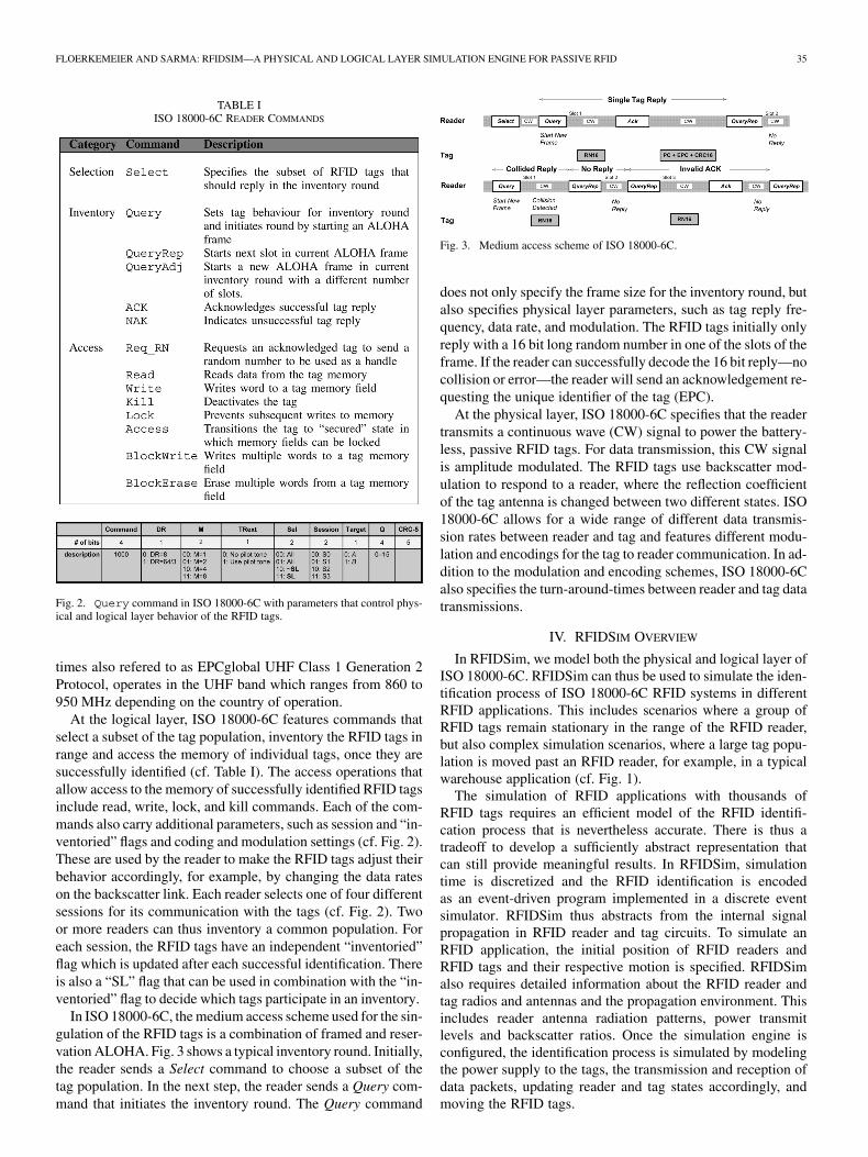
TABLE IISO 18000-6C READER COMMANDS
Fig. 2. Query command in ISO 18000-6C with parameters that control phys-ical and logical layer behavior of the RFID tags.
times also refered to as EPCglobal UHF Class 1 Generation 2
Protocol, operates in the UHF band which ranges from 860 to
950 MHz depending on the country of operation.
At the logical layer, ISO 18000-6C features commands that
select a subset of the tag population, inventory the RFID tags in
range and access the memory of individual tags, once they are
successfully identified (cf. Table I). The access operations that
allow access to the memory of successfully identified RFID tags
include read, write, lock, and kill commands. Each of the com-
mands also carry additional parameters, such as session and “in-
ventoried” flags and coding and modulation settings (cf. Fig. 2).
These are used by the reader to make the RFID tags adjust their
behavior accordingly, for example, by changing the data rates
on the backscatter link. Each reader selects one of four different
sessions for its communication with the tags (cf. Fig. 2). Two
or more readers can thus inventory a common population. For
each session, the RFID tags have an independent “inventoried”
flag which is updated after each successful identification. There
is also a “SL” flag that can be used in combination with the “in-
ventoried” flag to decide which tags participate in an inventory.
In ISO 18000-6C, the medium access scheme used for the sin-
gulation of the RFID tags is a combination of framed and reser-
vation ALOHA. Fig. 3 shows a typical inventory round. Initially,
the reader sends a Select command to choose a subset of the
tag population. In the next step, the reader sends a Query com-
mand that initiates the inventory round. The Query command
Fig. 3. Medium access scheme of ISO 18000-6C.
does not only specify the frame size for the inventory round, but
also specifies physical layer parameters, such as tag reply fre-
quency, data rate, and modulation. The RFID tags initially only
reply with a 16 bit long random number in one of the slots of the
frame. If the reader can successfully decode the 16 bit reply—no
collision or error—the reader will send an acknowledgement re-
questing the unique identifier of the tag (EPC).
At the physical layer, ISO 18000-6C specifies that the reader
transmits a continuous wave (CW) signal to power the battery-
less, passive RFID tags. For data transmission, this CW signal
is amplitude modulated. The RFID tags use backscatter mod-
ulation to respond to a reader, where the reflection coefficient
of the tag antenna is changed between two different states. ISO
18000-6C allows for a wide range of different data transmis-
sion rates between reader and tag and features different modu-
lation and encodings for the tag to reader communication. In ad-
dition to the modulation and encoding schemes, ISO 18000-6C
also specifies the turn-around-times between reader and tag data
transmissions.
IV. RFIDSIM OVERVIEW
In RFIDSim, we model both the physical and logical layer ofISO 18000-6C. RFIDSim can thus be used to simulate the iden-tification process of ISO 18000-6C RFID systems in differentRFID applications. This includes scenarios where a group ofRFID tags remain stationary in the range of the RFID reader,but also complex simulation scenarios, where a large tag popu-lation is moved past an RFID reader, for example, in a typicalwarehouse application (cf. Fig. 1).
The simulation of RFID applications with thousands ofRFID tags requires an efficient model of the RFID identifi-cation process that is nevertheless accurate. There is thus atradeoff to develop a sufficiently abstract representation thatcan still provide meaningful results. In RFIDSim, simulationtime is discretized and the RFID identification is encodedas an event-driven program implemented in a discrete eventsimulator. RFIDSim thus abstracts from the internal signalpropagation in RFID reader and tag circuits. To simulate anRFID application, the initial position of RFID readers andRFID tags and their respective motion is specified. RFIDSimalso requires detailed information about the RFID reader andtag radios and antennas and the propagation environment. Thisincludes reader antenna radiation patterns, power transmitlevels and backscatter ratios. Once the simulation engine isconfigured, the identification process is simulated by modelingthe power supply to the tags, the transmission and reception ofdata packets, updating reader and tag states accordingly, andmoving the RFID tags.
Authorized licensed use limited to: Imperial College London. Downloaded on June 07,2010 at 19:36:24 UTC from IEEE Xplore. Restrictions apply.
36 IEEE TRANSACTIONS ON AUTOMATION SCIENCE AND ENGINEERING, VOL. 6, NO. 1, JANUARY 2009
At the end of each simulation run, RFIDSim provides de-tailed communication statistics, such as average throughput, thedistribution of received signal strength, overall identificationrates and failed read, write, and kill commands. These perfor-mance statistics can help to evaluate different transmission con-trol strategies, protocol enhancements, reader collision avoid-ance schemes, and privacy approaches. Examples include thefollowing.
• Transmission Control Strategies for ISO 18000-6C. Toguarantee the fast and reliable identification of large tagpopulation, it is necessary to efficiently use the limitedcommunication bandwidth available to RFID systems.This necessitates transmission control strategies thatcontrol the broadcast probabilities of the RFID tags andmake appropriate use of ISO 18000-6C protocol features,such as “inventoried” and “SL” flags. RFIDSim providesa well-controlled test environment to compare differentapproaches without the need to deploy hundreds of RFIDtags and move them consecutively past an RFID reader inexperiments.
• Protocol Enhancements and Modifications to ISO
18000-6C. An RFID communication protocol, suchas ISO 18000-6C specifies physical layer parameters, suchas timing, coding and modulation, but also medium accessschemes, RFID reader commands, and RFID tag behavior.RFIDSim permits the evaluation of alternative mediumaccess schemes and command sets before any possibleimprovement is implemented on an experimental testbedor possibly in silicon.
• Privacy and Security Approaches. While the invisiblenature of RFID technology has many benefits from anautomation perspective, it is also the cause of some seriousprivacy concerns [3]. To address this issue, a number ofprivacy enhancing techniques have been proposed. Someof which increase the power consumption of RFID tags,require extended turn-around-times to compute crypto-graphic functions on the tags, or introduce the need toexchange additional data packets between RFID tagsand readers [14]. RFIDSim can be used to predict theimpact of these approaches on the identification of largetag population in typical RFID application, such as onmanufacturing lines and in distribution centers.
V. SIMULATION MODELS OF RFIDSIM
To simulate an RFID application, an RFID simulation engine
needs to model the powering and movement of the RFID tags,
the reception and transmission of the signals at the RFID readers
and tags, the commands specified in the corresponding RFID
communication protocol, and the corresponding behavior of the
RFID tags and the signal propagation between RFID readers
and tags. In the following sections, we show how these aspects
of the RFID identification process are modeled in RFIDSim.
A. RFID Reader
At the logical layer, the RFIDSim reader features all the com-
mands and command parameters specified in ISO 18000-6C.
This includes commands that select a subset of the tag popula-
tion, inventory the RFID tags in range and access the memory
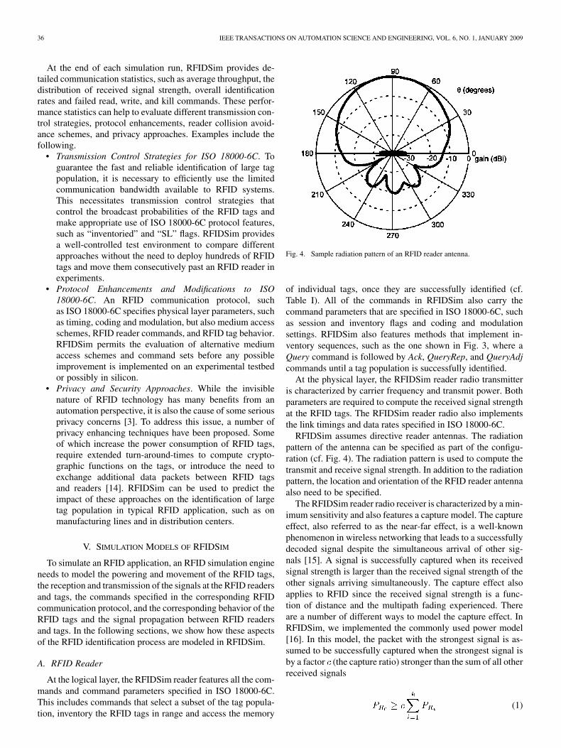
Fig. 4. Sample radiation pattern of an RFID reader antenna.
of individual tags, once they are successfully identified (cf.
Table I). All of the commands in RFIDSim also carry the
command parameters that are specified in ISO 18000-6C, such
as session and inventory flags and coding and modulation
settings. RFIDSim also features methods that implement in-
ventory sequences, such as the one shown in Fig. 3, where a
Query command is followed by Ack, QueryRep, and QueryAdj
commands until a tag population is successfully identified.
At the physical layer, the RFIDSim reader radio transmitter
is characterized by carrier frequency and transmit power. Both
parameters are required to compute the received signal strength
at the RFID tags. The RFIDSim reader radio also implements
the link timings and data rates specified in ISO 18000-6C.
RFIDSim assumes directive reader antennas. The radiation
pattern of the antenna can be specified as part of the configu-
ration (cf. Fig. 4). The radiation pattern is used to compute the
transmit and receive signal strength. In addition to the radiation
pattern, the location and orientation of the RFID reader antenna
also need to be specified.
The RFIDSim reader radio receiver is characterized by a min-
imum sensitivity and also features a capture model. The capture
effect, also referred to as the near-far effect, is a well-known
phenomenon in wireless networking that leads to a successfully
decoded signal despite the simultaneous arrival of other sig-
nals [15]. A signal is successfully captured when its received
signal strength is larger than the received signal strength of the
other signals arriving simultaneously. The capture effect also
applies to RFID since the received signal strength is a func-
tion of distance and the multipath fading experienced. There
are a number of different ways to model the capture effect. In
RFIDSim, we implemented the commonly used power model
[16]. In this model, the packet with the strongest signal is as-
sumed to be successfully captured when the strongest signal is
by a factor (the capture ratio) stronger than the sum of all other
received signals
(1)
Authorized licensed use limited to: Imperial College London. Downloaded on June 07,2010 at 19:36:24 UTC from IEEE Xplore. Restrictions apply.

FLOERKEMEIER AND SARMA: RFIDSIM—A PHYSICAL AND LOGICAL LAYER SIMULATION ENGINE FOR PASSIVE RFID 37
Fig. 5. RFID tag states defined in ISO 18000-6C.
where denotes the received signal strength of the strongest
signal, is the capture ratio, and denotes the received signal
strength of one of the other tag signals.
The noise model implemented in the receiver part is based on
a signal-to-noise ratio (SNR) and data transmission speed de-
pendent bit-error ratio (BER). Once a (single or captured) tag
reply is received, the probability of a corrupted packet is com-
puted using the number of bits in the packet (including the pre-
amble) and the corresponding bit error rate, which is determined
from the SNR and the data transmission speed. The noise floor
can be specified as one of the configuration parameters.
B. RFID Tag
Since ISO 18000-6C is a reader-talk-first protocol, RFID
tags never initiate the communication with the RFID reader,
but reply to commands from an RFID reader. Upon receiving
sufficient power from the reader, the tags power up and wait for
incoming commands. Upon successful decoding a command
and the corresponding flags, the RFID tags update their internal
state according to ISO 18000-6C (cf. Fig. 5) and reply with
the appropriate message. In RFIDSim, this process is mim-
icked and all RFID tags behave by default as specified in ISO
18000-6C. Note that Fig. 5 only shows a simplified version of
the tag state diagram defined in ISO 18000-6C. The detailed
state diagram can be found in [17].
At the physical layer, the RFIDSim tag radios use the same
noise model as the RFID reader radio—with the possibility to
set different parameters. Due to the battery-less nature of the
passive RFID tags, the communication with the RFID reader
is based on backscattering. The transmit power is thus a func-
tion of the incident signal strength and the backscatter ratio.
In RFIDSim, the backscatter power can be determined in two
different ways. There is a simple linear model that relates the
backscattered power to the received signal power
(2)
where denotes a constant that specifies which proportion of
the incident signal is reflected. is a function of the modu-
lation index, the modulation type (ASK or PSK) and the par-
ticular backscatter implementation on the tag [18]. The other
backscatter model implemented in RFIDSim uses a lookup table
that allows for a nonlinear relationship between the received
signal strength and the backscattered power. This model reflects
the behavior of a number of RFID tag microchips available
which backscatter signal strength does not follow the simple
proportional model of (2). There is also the possibility to specify
for how long the RFID tags keep their state after the reader
signal is no longer sufficient to power the RFID tag microchip.
All tag antennas in RFIDSim are assumed to be isotropic or
half-dipole antennas. The RFID tags can be distributed either by
specifying individual locations or by assigning a random distri-
bution in a predefined region like a tote. Furthermore, groups of
tags can then be associated with a velocity vector that specifies
magnitude and direction of the translation.
C. Signal Propagation
Passive RFID systems are typically operated in warehouses,
factories, distribution centers, and stores. Signal propagation in
these environments has been extensively investigated in the in-
door radio propagation channel literature [19]. In such indoor
environments, researchers have measured significant multipath
fading where the signal arriving from different paths, direct and
indirect, combine and produce a distorted version of the trans-
mitted signal. Since RFID communication is relatively narrow-
band, e.g., under European legislation the channels are 200 kHz
wide and under U.S. regulations 500 kHz, the multipath fading
results in fluctuations in the received signal strength and phase,
but no series of attenuated pulses [20]. This is due to the fact that
the difference in time delay of a number of paths is much less
than the reciprocal of the transmission bandwidth and the paths
cannot be resolved as distinct pulses. The RFID communication
channel is thus characterized by slow and flat fading. There is
also large-scale pathloss due to absorption. In this section, we
outline how these small- and large-scale effects are modeled in
RFIDSim.
At the macroscopic level, various pathloss models have been
suggested in the literature [20]. In the most commonly used
model, the received power expressed in terms of transmitted
power is attenuated by a factor , which is called the pathloss
(3)
where is the wavelength, is the distance between transmitter
and receiver, and is the pathloss exponent. In free space, the
pathloss follows a law .
RFIDSim implements this pathloss model. In RFIDSim, the
pathloss exponent can be adjusted to suit the characteristic of
the indoor propagation channel. The pathloss exponent can be
determined experimentally as outlined in [21] for a given envi-
ronment or estimated from comprehensive tables in the litera-
ture for different topographies and different materials [20].
As noted earlier, in a typical indoor RFID application, the
transmitted signal most often reaches the receiver by more than
one path resulting in multipath fading. The pathloss model is
thus not sufficient to characterize the signal propagation. The in-
door radio channel can be completely characterized as a linear
time-varying filter with an impulse response for each point in
Authorized licensed use limited to: Imperial College London. Downloaded on June 07,2010 at 19:36:24 UTC from IEEE Xplore. Restrictions apply.

38 IEEE TRANSACTIONS ON AUTOMATION SCIENCE AND ENGINEERING, VOL. 6, NO. 1, JANUARY 2009
Fig. 6. JiST system design [9]. Simulations are compiled, dynamically modi-fied by a byte-code rewriter and executed in the Java virtual machine.
space of the channel that captures the contribution of each di-
rect or indirect path [22]. In practice, this impulse response ap-
proach is frequently not adopted, since it is difficult to determine
all different multipaths in a given environment and the modeling
is site-specific. This is, in particular, true for RFID, where the
environment is not static. There are a number of statistical in-
door modeling approaches that show a good fit with measure-
ment data [19]. From an RFID perspective, we are, in partic-
ular, interested in those statistical models that describe the path
amplitude since reduced path amplitudes will cause the passive
RFID tag to loose power and, thus, affect the overall identifica-
tion performance. Since there is usually a strong line-of-sight
path or at least a path that undergoes much less attenuation than
the other arriving components in an RFID application, RFIDSim
supports Rician distributions to model the variation in received
signal strength [20]. Several researchers have shown that the Ri-
cian distribution is also suitable to model temporal variations
that are caused by the motion of people and equipment [23],
[24]. The temporal variations mean that the channel is nonsta-
tionary in space and time and deep fades can be observed [19].
VI. IMPLEMENTATION
In RFIDSim, the simulation model presented in the pre-
vious section is implemented in the simulation runtime JiST,
which stands for Java in Simulation Time and was developed
by Barr [7]. JiST is a discrete-event simulation engine that
runs over a standard Java virtual machine. JiST represents an
approach to building discrete-event simulators, called virtual
machine-based simulation, which unifies traditional systems
and language-based simulator designs. Simulation code that
runs on JiST need not be written in a specific simulation
language, nor need it be cluttered with system calls to support
runtime simulation functionality (cf. Figs. 6 and 7). Instead,
JiST converts an existing virtual machine into a simulation
platform by embedding simulation time semantics at the
byte-code level. Our RFID simulator is thus written in Java,
compiled using a regular Java compiler and run over a standard,
unmodified virtual machine.
We chose to use the JiST environment over other simulation
frameworks such as NS2 because JiST combines ease of soft-
ware development with high performance [9]. JiST compares
favorably with highly optimized simulation engines, such as
Parsec [6], with respect to event throughput and memory foot-
print [9]. The performance aspect is especially important in the
Fig. 7. Code example of RFIDSim. JiST transparently introduces simulationtime execution semantics to programs written in plain Java.
TABLE IIRFIDSIM ENTITIES AND THEIR DESCRIPTION
simulation of RFID application, where the wireless communica-
tion among thousands if not ten thousand nodes, needs to be sim-
ulated. RFIDSim reuses the pathloss and Rician fading model
of SWANS. We have added capture, antenna directivity, tag
backscatter and tag group mobility models, and implemented
the entire ISO 18000-6C communication protocol with all of its
timing options and command and command parameters.
The RFIDSim implementation consists of the entities shown
in Table II, which communicate with each other by sending
event messages to each other (cf. Fig. 8) and which implement
the simulation models described in the previous section.
The reader-tag communication can be implemented in a
discrete-event simulator in a straightforward way, since all data
packets exchanged can be represented as discrete events in the
simulation framework. This is not true for the continuous wave
(CW) reader signal that powers the tag microchip, since this
signal is inherently not discrete. In RFIDSim we approximate
the CW reader signal by periodic “power messages.” These
messages bypass the collision and noise models in the Tag
Radio. If the received signal strength of the “power message”
Authorized licensed use limited to: Imperial College London. Downloaded on June 07,2010 at 19:36:24 UTC from IEEE Xplore. Restrictions apply.
FLOERKEMEIER AND SARMA: RFIDSIM—A PHYSICAL AND LOGICAL LAYER SIMULATION ENGINE FOR PASSIVE RFID 39
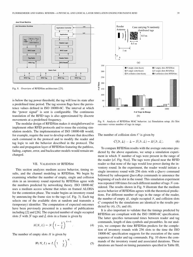
Fig. 8. Overview of RFIDSim architecture [25].
is below the tag power threshold, the tag will lose its state after
a predefined time period. The tag session flags have the persis-
tence values defined in ISO 18000-6C. The interval at which
the “power signal” is sent is configurable. The continuous
translation of the RFID tags is also approximated by discrete
movements at a predefined frequency.
The modular design of RFIDSim makes it straightforward to
implement other RFID protocols and to reuse the existing sim-
ulation models. The implementation of ISO 18000-6B would,
for example, require the user to develop software that describes
each command in the protocol and to modify the reader and
tag logic to suit the behavior described in the protocol. The
radio and propagation layer of RFIDSim featuring the pathloss,
fading, capture, error, and backscatter models would remain un-
changed.
VII. VALIDATION OF RFIDSIM
This section analyzes medium access behavior, timing re-
sults, and the channel modeling in RFIDSim. We begin by
examining whether the number of empty, single and collision
slots in an inventory round reported by RFIDSim agree with
the numbers predicted by networking theory. ISO 18000-6C
uses a medium access scheme that relies on framed ALOHA
for the contention phase. The reader begins an inventory round
by announcing the frame size to the tags (cf. Fig. 3). Each tag
selects one of the available slots at random and transmits a
(temporary) identifier. The computation of expected outcomes
have been previously presented in a number of publications
including [2] and [26]. The expected number of single occupied
slots with tags and slots in a frame is given by
(4)
The number of empty slots is given by
(5)
Fig. 9. Analysis of RFIDSim MAC behavior. (a) Simulation setup. (b) Slotoutcomes versus number of tags in range.
The number of collision slots is given by
(6)
To compare RFIDSim results with the average outcomes pre-
dicted by the above equations, we setup a simulation experi-
ment in which number of tags were present in the range of
the reader [cf. Fig. 9(a)]. The tags were placed near the RFID
reader so that none of the tags would lose power during the in-
ventory round. In the experiment, the reader would initiate a
single inventory round with 256 slots with a Query command
followed by subsequent QueryRep commands to announce the
beginning of each slot in the round. This simulation experiment
was repeated 100 times for each different number of tags con-
sidered. The results shown in Fig. 9 illustrate that the medium
access behavior of RFIDSim agrees with the theoretical predic-
tions. For different number of tags in the range of the reader,
the number of empty , single occupied , and collision slots
computed by the simulations are identical to the results pre-
dicted by (4), (5), and (6).
It is also important to validate that the timings predicted by
RFIDSim are compliant with the ISO 18000-6C specification.
The latter specifies turnaround times between reader and tag
commands, length of data symbols and preambles. In our anal-
ysis, we compare the time RFIDSim predicts for the comple-
tion of inventory rounds with 256 slots to the time the ISO
18000-6C specification suggests for the execution of the same
sequence of reader and tag commands. Fig. 10 shows the com-
mands of the inventory round and associated durations. These
durations are based on timing parameters specified in Table III,
Authorized licensed use limited to: Imperial College London. Downloaded on June 07,2010 at 19:36:24 UTC from IEEE Xplore. Restrictions apply.

40 IEEE TRANSACTIONS ON AUTOMATION SCIENCE AND ENGINEERING, VOL. 6, NO. 1, JANUARY 2009
Fig. 10. Durations of command sequences during tag inventory rounds. The du-rations are computed from the ISO 18000-6C parameters specified in Table III.
TABLE IIIISO 18000-6C TIMING PARAMETERS APPLIED
Fig. 11. Theoretical versus simulated duration of inventory round with 256slots in ISO 18000-6C.
which represent common choices for ISO 18000-6C operation
and which are within the range listed in the specification. The
total durations shown in Fig. 11 are a result of the multiplica-
tion the duration of empty, single occupied, and collision slots
with the expected number of corresponding outcomes predicted
by (4)–(6). Since the number of tags participating in the inven-
tory round influences its duration, we performed the tests with
different number of tags. The test setup is identically to the one
TABLE IVRFIDSIM SIMULATION PARAMETERS
described in the previously, where we analyzed the medium ac-
cess behavior [cf. Fig. 9(a)].
Fig. 11 shows that the RFID simulation results are in agree-
ment with the timings specified in ISO 18000-6C. The varia-
tion in the timings reported by RFIDSim results from the prob-
abilistic nature of the framed ALOHA scheme. It is evident that
inventory rounds with many single occupied slots takes signifi-
cantly longer than those with many empty or collision slot. This
results from the fact that a single occupied slot is followed by
the transmission of 128 bit long data packet that contains the
transponder identifier (EPC) (cf. Fig. 10). Since such an inven-
tory round involves a number of different reader and tag com-
mands, the timing analysis also implicitly verifies that RFIDSim
reader and tags send the correct messages with the appropriate
preamples.
The previous analysis focused on the medium access and log-
ical layer behavior of RFIDSim. Bit error, backscatter, pathloss,
and fading model of RFIDSim had no influence on the simula-
tion results since the tags were close to the reader. The prox-
imity to the reader meant that no tag lost power during the in-
ventory rounds and the received signal strength was relatively
high at tag and reader. We will now investigate to what extent
the pathloss and fading model of RFIDSim affect the received
signal strength as a tag is moved away from the RFID reader.
Fig. 12 shows the received signal strength at a tag that is moved
away from an RFID reader at a constant velocity of 1 m/s. The
figure shows the variation in received signal strength with the
RFIDSim pathloss model only and with the Rician fading and
pathloss model. The simulation experiment is characterized by
the parameters listed in Tables III and IV. Fig. 12 shows that
RFIDSim can model the deep fades that result from destructive
interference of multipath signals that cause RFID tags to lose
power and their state. With the pathloss model only, these deep
fades are not present.
Modeling these deep fades is important because they can
have a significant effect on the identification and data transfer
process. Fig. 13 illustrates how the number of tags participating
in an inventory round varies as a case with 200 tags is moved
away from the reader antenna at 1 m/s. As the RFID tags are
moving away from the reader antenna, tags enter a deep fade
more frequently during the inventory rounds. The RFID tags
Authorized licensed use limited to: Imperial College London. Downloaded on June 07,2010 at 19:36:24 UTC from IEEE Xplore. Restrictions apply.

FLOERKEMEIER AND SARMA: RFIDSIM—A PHYSICAL AND LOGICAL LAYER SIMULATION ENGINE FOR PASSIVE RFID 41
Fig. 12. Effect of Rician fading on received signal strength at RFID Tag. (a)Signal Strength versus distance. (b) Signal strength versus distance (magnified).
lose power and their state, e.g., number of slots in frame and
current slot number. Once they leave the deep fade and power
up, the RFID tags need to wait for the next Query command
to gather the information about the ongoing inventory process.
Without the Rician fading model (pathloss only), the number
of participating RFID tags is constant up to the point where the
received signal strength of the first tags in the case is less than
the tag sensitivity (cf. Fig. 13). The reduction of participating
RFID tags during an inventory round have important implica-
tions for throughput optimization. An optimal frame size at the
beginning of the frame with is unlikely to be optimal
towards the end of the frame because the effective number of
tags still powered is significantly reduced at this stage.
VIII. DISCUSSION—LIMITATIONS AND FUTURE WORK
The objective of RFIDSim was to develop a sufficiently ab-
stract representation of the RFID communication which can still
provide meaningful results. Fig. 14 shows that RFIDSim scales
to tag populations of 10 000 tags. The figure illustrates how the
time to simulate a single ISO 18000-6C inventory round with
256 slots increases as the number of tags that are present in the
range of the reader increases from 100 to 10 000. The simula-
tions are run on a notebook with a Intel Pentium M 1.50 GHz
CPU. In simulation time, the inventory round corresponds to
Fig. 13. Variation in size of tag populations participating in inventory roundswith and without Rician fading. (a) Simulation setup. (b) Number of tags par-ticipating in inventory round versus distance from reader.
Fig. 14. Time to complete simulated single inventory round with 256 slots withthe tags moving at a speed of 3 m/s.
about 200 ms (cf. Fig. 11), and the time to complete the simula-
tion takes approximately 10 min for 10 000 tags and 3 s for 10
tags.
While scalability to large number of RFID tags is important,
the RFID process also needs to be modeled accurately. The
previous section showed that RFIDSim models the timing and
medium access behavior specified in ISO 18000-6C accurately.
Since the wireless channel in multipath environments is nonsta-
tionary in time and space, the accurate prediction of the received
signal strength in a particular environment such as a warehouse
is known to be very difficult [20]. The received signal strength
Authorized licensed use limited to: Imperial College London. Downloaded on June 07,2010 at 19:36:24 UTC from IEEE Xplore. Restrictions apply.

42 IEEE TRANSACTIONS ON AUTOMATION SCIENCE AND ENGINEERING, VOL. 6, NO. 1, JANUARY 2009
is not only influenced by static objects such as walls and ceil-
ings reflecting the reader signal, but also by moving objects and
staff walking around in the vicinity of tags and readers. Without
on-site channel measurements, it is thus not possible to model
the wireless channel in a particular site accurately. In RFIDSim,
we chose to implement a statistical Rician-fading model instead.
The statistical fading model is capable of introducing the deep
fades that affect RFID operation. Important second-order statis-
tics such as the level crossing rates and average duration of fades
can be controlled to some extent by the interval at which the
power signal is transmitted to the tags. Previous work on indoor
channel measurements showed that these second-order statistics
are site and environment specific [27]. In RFIDSim, the samples
generated according to a Rician distribution are uncorrelated in
time and space. In reality, there is a correlation among the re-
ceived signal strength at locations in close proximity and in the
time domain [27]. RFIDSim is thus not capable of modeling a
specific RFID application exactly. Improvements resulting from
more accurate simulation approaches such as ray-tracing would
make the simulation environment less efficient and scalable.
RFIDSim currently also does not model the absorption of
the signal by the objects to which the RFID tags are attached.
In the simulation engine, the pathloss exponent is a constant
throughout the simulated area. In practice, the reader as well as
the tag signal are absorbed and reflected by the tagged objects.
Tag detuning, which results from the change of the tag antenna
impedance due to the material in its immediate vicinity, can
be incorporated by adjusting the tag sensitivity appropriately.
RFIDSim also does not model variations in the tag sensitivity
among different RFID tags. In practice, RFID tags vary in sen-
sitivity because of manufacturing tolerances in the tag antenna
manufacturing and assembly process.
While RFID reader antenna radiation patterns can be speci-
fied, the current version of RFIDSim only considers isotropic
and half-dipole tag antennas. The simulation engine currently
lacks support for multiple readers and multiple reader antennas.
Support for multiple readers increase the value of the simula-
tions significantly since we can now evaluate different reader
collision strategies, such as synchronization, listen-before-talk
and frequency hopping.
To compare the tag model implemented in RFIDSim with the
behavior of actual RFID tags, future work could also include
hardware-in-the-loop testing [28]. RFIDSim would be used to
generate the reader commands and to compute the propaga-
tion loss. The corresponding RFIDSim event comprising among
others the bits transmitted, received signal strength, and fre-
quency would then be converted into the appropriate waveforms
and directly applied to the input pins of a tag microchip. This
approach could be used to validate the state machine in the
RFIDSim tags and RFIDSim backscatter models.
IX. CONCLUSION
Radiofrequency identification poses a number of research
challenges. This includes protecting the privacy of the indi-
vidual and speeding up the identification of large tag popula-
tions. However, in practice, it is difficult to evaluate many of the
new approaches proposed to solve these issues. The evaluation
typically requires novel microchip designs for the tags, others
require update to the firmware of a reader. The result is that
frequently the impact of novel RFID approaches on the iden-
tification performance is difficult to assess. In this paper, we
present the RFID simulation engine, RFIDSim, that implements
the ISO 18000-6C RFID communication protocol. RFIDSim is
implemented in a discrete-event simulator and models signal
propagation using a pathloss model and a Rician distribution
based multipath model. There is also support for different
capture, backscatter, interference, and tag mobility models. The
low memory footprint and high throughput that results from the
use of the JiST simulation platform and the efficient simulation
models chosen provide scalability to simulations of thousands
of tags. The result is that RFIDSim can be used to simulate
typical RFID applications, such as conveyor belts and fork lifts
moving pallets with large tag populations. The simplicity with
which novel algorithms can be implemented on the simulated
tags and readers also means that the performance of different
transmission control strategies and settings in ISO 18000-6C
can be readily evaluated.
Since RFIDSim models the multipath fading statistically and
the absorption of signals by the tagged objects and tag antenna
detuning is neglected, the simulation results of RFIDSim will
not be identical to the outcomes of actual experiments with
RFID tags and readers in a specific application. RFIDSim is thus
not envisioned as a tool to predict the identification performance
in a specific scenario. We believe, however, that RFIDSim will
significantly facilitate the relative comparison of different trans-
mission control strategies, settings in ISO 18000-6C and privacy
and security approaches.
ACKNOWLEDGMENT
The authors would like to thank the graduate students
M. Wille, T. Vogel, and B. Gasser at ETH Zurich for their
contributions to the implementation of the RFIDSim software.
REFERENCES
[1] C. Floerkemeier, “Bayesian transmission strategy for framed ALOHAbased RFID protocols,” in Proc. IEEE Int. Conf. RFID, 2007, pp.228–235.
[2] H. Vogt, F. Mattern and M. Naghshineh, Eds., “Efficient object identi-fication with passive RFID tags,” in Proc. 1st Int. Conf., PERVASIVE
2002, Zurich, Switzerland, Aug. 2002, vol. 2414, Lecture Notes inComputer Science (LNCS), pp. 98–113.
[3] S. A. Weis, S. E. Sarma, R. L. Rivest, and D. W. Engels, “Securityand privacy aspects of low-cost radio frequency identification systems,”in Proc. 1st Annu. Conf. Security in Pervasive Computing, 2003, pp.201–212.
[4] K. Fall and K. Varadhan, The ns Manual. [Online]. Available: http://www.isi.edu/nsnam/ns/ns-documentation.html
[5] X. Zeng, R. Bagrodia, and M. Gerla, “GloMoSim: A library for parallelsimulation of large-scale wireless networks,” in Proc. 12th Workshop
on Parallel and Distributed Simulation, May 1998, pp. 154–161.[6] R. Bagrodia, R. Meyer, M. Takai, Y. Chen, X. Zeng, J. Martin, and
H. Y. Song, “Parsec: A parallel simulation environment for complexsystems,” Computer, vol. 31, no. 10, pp. 77–85, Oct. 1998.
[7] R. Barr, “An efficient, unifying approach to simulation using virtualmachines,” Ph.D. dissertation, Cornell University, Ithaca, NY, May2004.
[8] R. Barr, SWANS—Scalable Wireless Ad Hoc Network Simulator, UserGuide, 2004. [Online]. Available: http://jist.ece.cornell.edu/docs
[9] R. Barr, Z. J. Haas, and R. van Renesse, “JiST: An efficient approachto simulation using virtual machines,” Software—Practice and Experi-
ence, vol. 35, no. 6, pp. 539–576, May 2005.[10] Y. Han and H. Min, “System modeling and simulation of RFID,”
Auto-ID Labs Whitepaper, Sep. 2005.
Authorized licensed use limited to: Imperial College London. Downloaded on June 07,2010 at 19:36:24 UTC from IEEE Xplore. Restrictions apply.

FLOERKEMEIER AND SARMA: RFIDSIM—A PHYSICAL AND LOGICAL LAYER SIMULATION ENGINE FOR PASSIVE RFID 43
[11] K. S. Leong, M. L. Ng, and P. Cole, “Operational considerations insimulation and deployment of RFID systems,” in Proc. 17th Int. Zurich
Symp. Electromagnetic Compatibility, 2006, pp. 521–524.[12] Y. Kawakita and J. Mitsugi, “Anti-collision performance of Gen2 air
protocol in randam error communication link,” in Proc. SAINT 2006
Workshops, Jan. 2006, pp. 68–71.[13] S. Dominikus and M. Aigner, “Petra.” [Online]. Available: http://jce.
iaik.tugraz.at/sic/products/rfid_components/petra_software__1[14] A. Juels, “RFID security and privacy: A research survey,” IEEE J. Sel.
Areas Commun., vol. 24, no. 2, pp. 381–394, Feb. 2006.[15] L. Roberts, “ALOHA packet system with and without slots and cap-
ture,” Comput. Commun. Rev., vol. 5, no. 2, pp. 28–42, 1975.[16] M. Zorzi and R. Rao, “Capture and retransmission control in mobile
radio,” IEEE J. Sel. Areas Commun., vol. 12, no. 8, pp. 1289–1298,Oct. 1994.
[17] Class 1 Generation 2 UHF Air Interface Protocol Standard Version
1.0.9, EPCglobal, 2005. [Online]. Available: www.epcglobalinc.org[18] U. Karthaus and M. Fischer, “Fully integrated passive UHF RFID
transponder IC with 16.7-�W minimum RF input power,” IEEE J.
Solid-State Circuits, vol. 38, no. 10, pp. 1602–1608, Oct. 2003.[19] H. Hashemi, “The indoor radio propagation channel,” Proc. IEEE, vol.
81, no. 7, pp. 943–968, Jul. 1993.[20] T. S. Rappaport, Wireless Communications, 2nd ed. Englewood
Cliffs, NJ: Prentice-Hall, 2002.[21] K. S. Leong, M. L. Ng, and P. H. Cole, “The reader collision problem
in RFID systems,” in Proc. IEEE 2005 Int. Symp. Microwave, An-
tenna, Propagation and EMC Technologies for Wireless Communica-
tions (MAPE 2005), Beijing, China, 2005.[22] G. Turin, F. Clapp, T. Johnston, S. Fine, and D. Lavry, “A statistical
model of urban multipath propagation,” IEEE Trans. Veh. Technol., vol.21, no. 1, pp. 1–9, Feb. 1972.
[23] R. Bultitude, “Measurement, characterization and modeling of indoor800/900 MHz radio channels for digital communications,” IEEE
Commun. Mag., vol. 25, no. 6, pp. 5–12, Jun. 1987.[24] T. Rappaport and C. McGillem, “UHF fading in factories,” IEEE J. Sel.
Areas Commun., vol. 7, no. 1, pp. 40–48, Jan. 1989.[25] M. Wille, “Evaluation and Optimization of RFID Transmission Control
Strategies,” Master’s thesis, ETH Zurich, Zurich, Switzerland, Mar.2005.
[26] F. C. Schoute, “Dynamic frame length ALOHA,” IEEE Trans.
Commun., vol. COM-31, no. 4, pp. 565–568, Apr. 1983.[27] H. Hashemi, M. McGuire, T. Vlasschaert, and D. Throll, “Measure-
ments and modeling of temporal variations of the indoor radio propa-gation channel,” IEEE Trans. Veh. Technol., vol. 43, no. 3, pp. 733–737,Aug. 1994.
[28] H.-J. Herpel, M. Held, and M. Glesner, “Mcems toolbox—A hard-ware-in-the-loop simulation environment for mechatronic systems,”in Proc. 2nd Int. Workshop on Modeling, Analysis, and Simulation
on Computer and Telecommunication Systems, MASCOTS’94, Wash-ington, DC, 1994, pp. 356–357.
Christian Floerkemeier received the B.S. andM.Eng. degrees in electrical and information sci-ence with distinction from Cambridge University,Cambridge, U.K., in 1999 and the Ph.D. degree incomputer science from ETH Zurich, Switzerland, in2006.
He is currently a Research Scientist at the Massa-chusetts Institute of Technology (MIT), Cambridge.Before joining the Auto-ID Laboratory, MIT, he wasAssociate Director of the Swiss Auto-ID Laboratory,ETH Zurich. From 1999 to 2001, he worked as Head
of Software Development for Ubiworks, an Amsterdam-based software com-pany. His research interests include radio-frequency identification systems andpervasive computing.
Sanjay Sarma received the B.S. degree from theIndian Institute of Technology, Delhi, the M.S.degree from Carnegie Mellon University, Pittsburgh,PA, and the Ph.D. from the University of California,Berkeley.
He is an Associate Professor of MechanicalEngineering at the Massachusetts Institute of Tech-nology (MIT). In between degrees, he worked atSchlumberger Oilfield Services, Aberdeen, U.K. Hewas one of the founders of the Auto-ID Center, MIT,which developed many of the technical concepts
and standards of RFID. His current research projects are in the areas of radiofrequency identification, IC packaging, manufacturing, CAD/CAM, machinedesign, RFID applications, device networking, and smart devices.
Prof. Sarma is a recipient of the MIT MacVicar Fellowship, National Sci-ence Foundation CAREER Award, the Cecil and Ida Green Career DevelopmentChair at MIT, the Den Hartog Award for Excellence in Teaching, the KeenanAward for innovations in undergraduate education, the New England Businessand Technology Award, and the MIT Global Indus Award.
Authorized licensed use limited to: Imperial College London. Downloaded on June 07,2010 at 19:36:24 UTC from IEEE Xplore. Restrictions apply.