Embed Size (px)
Citation preview

Siemens FS 10 · 2008
RFID systems
4/2 Introduction
4/3 RFID systems for production
4/6 MOBY E4/7 Mobile data storage unit4/9 MDS E6004/10 MDS E6114/11 MDS E6234/12 MDS E6244/13 Write/read devices4/15 SIM 70 with ANT 04/17 SIM 70 with ANT 14/19 SLG 72/SIM 724/21 SLG 75 with ANTx4/25 SLA 714/26 STG E mobile handheld
terminal4/28 Configuring notes
4/30 MOBY I 4/31 Mobile data storage unit4/33 MDS 4014/34 MDS 4024/35 MDS 4034/36 MDS 4044/37 MDS 5064/38 MDS 5144/39 MDS 439E4/41 Write/read devices4/42 SLG 40/SLG 40S4/44 SLG 41/SLG 41S4/45 SLG 424/46 SLG 434/47 SIM 414/49 STG I mobile handheld
terminal4/51 Configuring notes
4/52 SIMATIC RF3004/54 Mobile data storage unit4/55 SIMATIC RF320T4/56 SIMATIC RF340T4/57 SIMATIC RF350T4/58 SIMATIC RF360T4/59 SIMATIC RF370T4/60 SIMATIC RF380T4/62 Write/read devices4/63 SIMATIC RF310R4/65 SIMATIC RF340R4/66 SIMATIC RF350R4/69 SIMATIC RF310M mobile
handheld terminal
4/71 MOBY U4/73 Mobile data storage unit4/74 MDS U315/MDS U524/
MDS U5254/76 MDS U5894/78 MDS U Service
4/80 Write/read devices4/80 SLG U924/83 STG U mobile handheld
terminal 4/85 Configuring notes
4/87 RFID systems for logistics
4/89 MOBY D4/91 Mobile data storage unit4/93 MDS D1004/94 MDS D1244/95 MDS D1394/96 MDS D1604/97 MDS D3244/98 SmartLabel4/99 Write/read devices4/101 SLG D10/SLG D10S ba-
sic unit with ANT D5 and ANT D6 and ANT D10 antenna
4/104 SLG D10 ANT D5/SLG D10S ANT D5
4/106 SLG D11 ANT D5/SLG D11S ANT D5
4/108 SLG D12/SLG D12S4/110 STG D mobile handheld
terminal4/112 Configuring notes
4/114 SIMATIC RF6004/116 Mobile data storage unit4/116 SIMATIC RF620L4/117 SIMATIC RF630L4/119 SIMATIC RF640T4/120 Write/read device and
antenna4/120 SIMATIC RF660R
SIMATIC RF660A
4/123 RFID systems for locating
4/123 MOBY R4/126 Mobile data storage unit4/128 MDS R2004/129 MDS R2024/130 MDS R2074/131 Write/read devices4/132 SLG R21/R234/134 TRIG R2014/135 STG R mobile handheld
terminal4/136 Configuring notes
4/137 Communication modules
4/139 ASM 4504/141 ASM 4564/144 SIMATIC RF180C4/147 SIMATIC RF170C4/149 ASM 470/4754/151 ASM 424,
ASM 754/724
4/153 Software4/154 SIMATIC RF-MANGER
4/156 Accessories for RFID systems
4/158 Documentation

RFID SystemsIntroduction
4/2 Siemens FS 10 · 2008
4
RFID systems –for optimization of material flow and logisticsA constant flow of information is essential for seamless, efficient processes. In a wide range of different sectors, the intelligent RFID systems MOBY D, MOBY E, MOBY I, MOBY R, MOBY U, SIMATIC RF300 and RF600 ensure that you are always in the picture. This system family offers you considerable advantages over conventional identification systems.
Important data accompany a product or object from the start. Contactless data transfer provides for high levels of industrial compatibility. And the uniform system integration ensures easy and low-cost integration in the application. In short: With the RFID systems, you can perfectly control and optimize your material flow and your logistics.
Meaningful data from the outset
The RFID systems ensure that meaningful data accompanies a product or object from the very beginning. The mobile data memories (MDS or tag/transponder) are attached to the product, product carrier, object or its transport or packing unit and are written by non-contact methods. This means that all the applica-tion-specific data is available on the mobile data memory. This is true whether you are dealing with vehicle body parts in the auto-motive industry or order picking boxes. Up to 32 KB of data can be stored and individually read and supplemented when re-quired at the various workstations or manufacturing stations. This all means that the flow of material and data is synchronized optimally.
Contactless data transfer and a high degree of industrial compatibility
Powerful write/read devices (SLG) in various rugged designs ensure fast and reliable data transfer between the mobile data memories and the higher-level systems (PLC, PC, ...).
The data and power are transmitted inductively by an electro-magnetic alternating field or by radio waves. This principle of contactless data transfer works reliably in the presence of con-tamination or through non-metallic materials.
Perfectly matched components
The RFID systems consist of perfectly matched individual components:• Mobile data memories (tags)• Read/write devices and mobile handheld terminals (readers)• Antennas• Interfaces for connection to the automation system
(PROFIBUS, Ethernet)• Software for system integration
Suitable for every sector• Assembly lines• Conveyor systems• Industrial manufacturing• Warehouses• Logistics• Distribution• Order picking
Broad range of mobile data memories
A wide range of different mobile data memories is available using a variety of storage technologies (fixed code, EEPROM or FRAM/SRAM) and geometric designs. Their strength is not only their high level of data security but also the excellent high de-gree of protection against ambient conditions such as contami-nation, temperature fluctuations, washing water or shock load.
Flexible system integration
No matter what the requirements are: The RFID systems allow easy system integration into SIMATIC or SINUMERIK, in the PROFIBUS, Ethernet or a PC environment, and can be con-nected to any controller.
A wide range of communication modules, function blocks and powerful drivers and function libraries make integration into the application a quick an easy affair.
Highlights• Save time in production and logistics• Fully automatic, fast identification, with 100% transmission
reliability• Production and quality data can be saved directly on the
product• Insensitive to temperature fluctuations and contamination• Broad range of repeatedly reusable data memories –
from SmartLabels to 32 KB tags• Flexible system integration: serial, via PROFIBUS or
Ethernet• Easy integration into SIMATIC reduces engineering
costs• Support for ISO 14443, ISO 15693, ISO 18000-2,
ISO 18000-4 standards as well as EPCglobal andISO/IEC 18000-6

RFID systems for productionIntroduction
4/3Siemens FS 10 · 2008
4
RFID systems for production – strong in performance and ruggedConditions can sometimes be extremely harsh in the vicinity of assembly lines and industrial production. This is not a problem for the RFID systems and the systems specially developed for in-dustrial applications. These are highly effective for both reading and writing as well as extremely reliable and feature high de-grees of protection up to IP68.
They are characterized by a high level of data security and a large memory capacity, they can manage large volumes of data, communicate at lightning speed and are extremely resistant to interference. Because they are also especially easy to configure and install, they not only ensure reliable identification but also provide cost savings over the complete production line.
Finely graded systems are available for optimizing material flow and for controlling production to suit simple or complex tasks.
Application• Main assembly lines in the automotive industry such as body
shop, paint shop, final assembly• Production lines for engines, gearboxes or steering gear• Conveyor systems for the assembly of anti-skid brake sys-
tems, airbags, brake systems, doors and cockpits• Assembly lines for household electrical appliances, consumer
electronics or electronic communication equipment• Assembly lines for PCs, low-power motors, contactors or
switches• Production lines in the glass and ceramics industry
Highlights• Suitable for use under the harshest conditions –
high degree of protection up to IP68 as well as being insensitive to interference
• Large range of data memories – from the most compact sizes for flush mounting in conveyor systems with small workpiece holders through to high-temperature versions
• Seamless integration into SIMATIC reduces engineering costs
• Production and quality data can be saved directly on the product
Production
MOBY E MOBY I SIMATIC RF300 MOBY U
Read/write distance Up to 0.1 m Up to 0.15 m Up to 0.2 m Up to 3.0 m
Frequency 13.56 MHz 1.81 MHz 13.56 MHz 2.4 GHz
Standards ISO 14443-A ISO 18000-4

RFID systems for productionIntroduction
4/4 Siemens FS 10 · 2008
4
■ Technical specifications
MOBY E MOBY I
Write/read distance Up to 100 mm Up to 150 mm
Data transmission rate ≥ 2.55 ms/byte reading, ≥ 2.8 ms/byte writing Typically 0.8 ms/byte
Memory EEPROM FRAM
Standards ISO 14443-A
Approvals ETS 300330 (Europe); FCC Part 15 (USA), UL/CSA EN 300330 (Europe), FCC Part 15 (USA), UL/CSA
Bulk capability • (only with SIM) –
Multitag capability • (only with SIM) –
Frequency 13.56 MHz 1.81 MHz
Mobile data storage (tags) Designation Memory size
Operating temperature
Degree of protection
Designation Memory size Operating temperature
Degree of protection
MDS E600MDS E611MDS E623MDS E624
752 Byte752 Byte752 Byte752 Byte
-25 ... +60 °C-25 ... +75 °C-25 ... +85 °C-25 ... +125 °C
IP68IP67IP67/IPX9KIP67/IPX9K
MDS 402MDS 401MDS 403MDS 404MDS 506MDS 514MDS 439E
8 KB FRAM8 KB FRAM8 KB FRAM8 KB FRAM32 KB FRAM32 KB FRAM8 KB FRAM
-25 ... +70 °C-25 ... +85 °C-25 ... +85 °C-25 ... +70 °C-25 ... +70 °C-25 ... +85 °C-25 ... +110 °C
(+220 °C)
IP68/IPX9KIP67IP68/IPX9KIP68/IPX9KIP68IP68/IPX9KIP68
Write/read devices Designation Operating temperature
Degree of protection Designation Operating temperature
Degree of protection
Stationary, with detached antenna
SIM 70 with ANT 0SIM 70 with ANT 1SLG 75
-25 ... +75 °C
-25 ... +75 °C
-25 ... +75 °C
IP65/IP67
IP65/IP67
IP65
SLG 40S (incl. antenna)SLG 40(incl. antenna)
-25 ... +70 °C
-25 ... +70 °C
IP65
IP65
Stationary, with integrated antenna
SLG 72SIM 72
-25 ... +75 °C-25 ... +75 °C
IP65IP65
SLG 41SSLG 41SLG 42SLG 43SIM 41
-25 ... +70 °C-25 ... +70 °C-25 ... +70 °C-25 ... +70 °C
0 ... +60 °C
IP65IP65IP65IP65IP54
Mobile handheld terminal with integrated antenna
STG E -20 ... +50 °C IP54 STG I -20 ... +50 °C IP54
Antennas Designation Operating temperature
Degree of protection Designation Operating temperature
Degree of protection
SLA 71ANT 1ANT 12ANT 18ANT 30ANT 4
-25 ... +70 °C-25 ... +70 °C-25 ... +70 °C-25 ... +70 °C-25 ... +70 °C-25 ... +70 °C
IP65IP65IP65IP65IP65IP65
Connection to the automation system
directly via communication module (ASM)
directly via communication module (ASM)
SIMATIC S7-300, S7-400 • •PROFIBUS DP 1111• •PROFINET • •Serial interface to other controllers, PCs, any other systems
• • • •
Page 4/6 4/30

RFID systems for productionIntroduction
4/5Siemens FS 10 · 2008
4
SIMATIC RF300 MOBY U
up to 200 mm1) 150 … 3,000 mm Write/read distance
50 byte/s or 3 KB/s Approx. 8 or 4.8 KB/s without bulk (net) Data transmission rate
FRAM/EEPROM RAM Memory
ISO 18000-4 Standards
CE, UL1), FCC, CSA EN 300440-2, FCC Part 15C, UL/CSA Approvals
• • (max. 12) Bulk capability
• (max. 4) • (max. 12) Multitag capability
13.56 MHz 2.4 GHz ... 2.4835 GHz Frequency
Designation Memory size
Operating temperature
Degree of protection
Designation Memory size
Operating temperature
Degree of protection
Mobile data storage (tags)
RF320TRF340TRF350TRF360TRF370TRF380T
20 bytes8188 bytes32765 bytes8188 bytes65276 bytes32765 bytes
-25 ... +85 °C-25 ... +85 °C-25 ... +85 °C-25 ... +75 °C-25 ... +85 °C-25 ... +110 °C (+220 °C)
IP67/IPX9KIP68/IPX9KIP68IP67IP68IP68
MDS U315MDS U524MDS U525MDS U589
MDS U Service
2 KB RAM32 KB RAM32 KB RAM32 KB RAM
32 KB RAM
-25 ... +70 °C-25 ... +85 °C-25 ... +85 °C-25 ... +85 °Cto 220 °C cycl.-25 ... +70 °C
IP65IP68IP65IP68
IP40
Designation Operating temperature
Degree of protection Designation Operating temperature
Degree of protection Write/read devices
RF350R -25 ... +70 °C IP65 Stationary, with detached antenna
RF310RRF340R
-25 ... +70 °C-25 ... +70 °C
IP67IP67
SLG U92 -25 ... +70 °C IP65 Stationary, with integrated antenna
RF310M -10 ... +50 °C IP54 STG U -20 ... +60 °C IP54 Mobile handheld terminal with integrated antenna
Designation Operating temperature
Degree of protection Designation Operating temperature
Degree of protection Antennas
directly via communication module (ASM)
directly via communication module (ASM)
Connection to the automation system
• • SIMATIC S7-300, S7-400
1111• • PROFIBUS DP
1111• 1111• PROFINET
• (via RS422) • Serial interface to other controllers, PCs, any other systems
4/52 4/71 Page
1) Available soon

RFID systems for productionMOBY E
Introduction
4/6 Siemens FS 10 · 2008
4
■ Overview
MOBY E is a contactless identification system that has been specially designed for applications in logistics, distribution and industrial production.
Depending on requirements (EEPROM, size, ambient condi-tions, large clearance etc.), different data memories and write/read devices are available. Thanks to their low price, these data memories can be used, for example, as an "electronic barcode substitute" or "delivery note".
The MOBY E identification system boasts the following features:• 13.56 MHz identification system with write/read distance of up
to 100 mm• Designed for the upper and medium performance range• Extensive range of battery-free data memories (752 bytes
EEPROM, up to + 150 °C) including a special data memory for tool identification.
• Very high level of reliability even in the presence of contamina-tion, temperature fluctuations and electromagnetic interfer-ence.
• Simple integration into SIMATIC and the PROFIBUS DP• Can be connected via serial interface to any system, e.g. PC
with DOS / Windows 95/NT
■ Benefits
• The standard MOBY E components permit the secure and quick construction of application-specific identification sys-tems, so that capacities are freed up for the generation of the application software.
• Worldwide support, configuration and service support.
■ Application
MOBY E is used wherever containers, boxes, carriers, work-piece carriers, tools and hangers have to be identified reliably, quickly, automatically and without contact.
The main applications for MOBY E are:• Logistics (identification of pallets, charge carriers, containers
etc.)• Distribution (data memory as "electronic barcode supplement"
or "delivery note")• Parts identification (e.g. data storage is attached to prod-
ucts/pallets).• Assembly lines (e.g. data memory is attached to workpiece
carriers)• Conveyor systems (e.g. data memory is attached to the
hanger of an overhead conveyor).
■ Function
MOBY identification systems ensure that important data accom-panies the product from the very beginning.
Mobile data memories ("electronic goods notes") are used in place of barcodes and already contain all product-specific data in addition to the product number. Up to 752 byte of user data can be stored and managed in this way. Enough to enable qual-ity data to be stored as well.
Using stationary as well as mobile read/write devices (SLGs), the necessary information (production data, transport routes, etc.) can be read without contact (inductively), and even be sup-plemented or modified without the need for a direct line-of-sight link. MOBY records the data of objects quickly and reliably. MOBY thereby ensures effective and cost-effective automation.
■ Technical specifications
Type Contactless RF identification system for the lower and medium performance range
Transmission frequency data/energy
13.56 MHz
Memory capacity 752 byte user memory4 byte fixed codeas serial number
Memory type EEPROM
Write/read cycles > 1 000 000/unlimited
Data management Bytewise access (16-byte block organization internally)
Data transmission rate from mobile data storage unit to read/write device
≥ 2.8 ms/byte
Read/write distance Up to 100 mm
Operating temperature -25 to +125 °C
Degree of protection IP67, IP68
Can be connected to SIMATIC S5/S7, PC, non-Siemens PLC, PROFIBUS DP
Special features • CRC checksums for secure data transmission
• High resistance to interference frequencies
• Multitag and password function (SIM only)
Approvals ETS 300330 (Europe),FCC Part 15 (USA), UL/CSA

RFID systems for productionMOBY E mobile data storage unit
Introduction
4/7Siemens FS 10 · 2008
4
■ Overview
1) Extract:Test equipment: Steam jet-air ejector 0 °C, 30 °C, 60 °C, 90 °CWater flow: 0 to 15 l/min at 100 bar (75 °C)Distance: 10 to 15 cm
■ Design
The MOBY E data storage mainly comprises logic, an antenna and an EEPROM memory.
■ Function
If an MDS moves into the transmission field of the SLG, the necessary power for all circuit components is generated and monitored by means of the energy supply unit. The pulse-coded information is prepared in such a way that it can be processed further as pure digital signals. The handling of data, including check routines, is performed by the control unit which also manages the user memory.
Type Feature
MDS E600 Universal data storage unit (752 byte EEPROM) in credit card format (85 mm x 54 mm x 0.8 mm)• Degree of protection IP68• Temperature range up to +60 °C• Max. read/write distance 70 mm
MDS E611 Universal data storage unit (752 byte EEPROM) in credit card format (85 mm x 54 mm x 2.5 mm)This mobile data medium can also be used in harsh environments and under extreme conditions• Degree of protection IP67• Temperature range up to +75 °C• Max. read/write distance 100 mm
MDS E623 Small data memory (752 byte EEPROM, Ø 10 mm x 4.5 mm ), specially for tool coding according to DIN 69873• Degree of protection
IP67/IPX9K 1) to DIN EN 60529 / VDE 0470-1
• Temperature range up to +85 °C• Max. read/write distance 6 mm
MDS E624 Universal compact data memory (752 byte EEPROM), Ø 27 mm x 4 mm• Degree of protection
IP67/IPX9K 1) to DIN EN 60529 / VDE 0470-1
• Temperature range up to +125 °C• Max. read/write distance 40 mm

RFID systems for productionMOBY E mobile data storage unit
Introduction
4/8 Siemens FS 10 · 2008
4
■ Technical specifications
Field data of MDS and SLG (all dimensions in mm)
The field data for all MOBY E components of the MDS and SLG are shown in the tables below. Thus it becomes particularly easy to select the right MDS and SLG. All the technical data listed is typical data and is applicable for an ambient temperature of between 0 °C and +50 °C and a supply voltage of between 22 V and 27 V DC.
Operating/limit distance (without influence of metal)
Distance from MDS to MDS
Type MDS E600 MDS E611 MDS E623 MDS E624
SLG 70 with ANT 0/SIM 70 with ANT 0
- - 0 - 4/6 0 - 8/15
SLG 70 with ANT 1/SIM 70 with ANT 1
0 - 50/70 10 - 70/100 - 0 - 25/40
SLG 72 / SIM 72 0 - 50/70 10 - 70/100 - 0 - 30/40
SLA 71 0 - 50/70 10 - 70/100 - 0 - 25/40
SLG 75 with ANT 1 0 - 50/70 10 - 70/100 - 0 - 25/40
SLG 75 with ANT 4 0 - 50/70 10 - 70/100 - 0 - 25/40
SLG 75 with ANT 12 - - 0 - 4/5 -
SLG 75 with ANT 18 - - 0 - 4/6 0 - 8/15
SLG 75 with ANT 30 - - - 0 - 18/24
Type MDS E600 MDS E611 MDS E623 MDS E624
SIM 70 with ANT 0 - - > 30 > 50
SIM 70 with ANT 1 > 400 > 400 - > 250
SLG 72/SIM 72/ SLA 71 > 400 > 400 - > 250
SLG 75 with ANT 1 > 400 > 400 - > 250
SLG 75 with ANT 4 > 400 > 400 - > 250
SLG 75 with ANT 12 - - > 20 -
SLG 75 with ANT 18 - - > 30 > 50
SLG 75 with ANT 30 - - - > 60

RFID systems for productionMOBY E mobile data storage unit
MDS E600
4/9Siemens FS 10 · 2008
4
■ Overview
Universal data memory (752 byte EEPROM) in credit card format (85 mm x 54 mm x 0.8 mm), degree of protection IP68, tem-perature range up to +60 °C and a max. write/read distance of 70 mm.
■ Technical specifications
■ Selection and Ordering data
A: Subject to export regulations AL = N and ECCN = EAR99H
■ Dimensions
Mobile data storage unit MDS E600
Memory size 752 byte of EEPROM available
MTBF 2 x 10⁶ hours
Read cycles Unlimited
Write cycles, min. 200000
at ≤ 40 °C, typical > 1000000
Data retention time > 10 years (at < +40 °C)
Read/write distance, max. 70 mm (see field data)
Memory organization Bytewise access (16-byte block organization internally)
Energy source Inductive power transmission
Shock/vibration ISO 10373/ISO 7810
Torsion and bending load ISO 10373/ISO 7816-1
Mounting technique Fixing lug/adhesive
Recommended distance to metal ≥ 20 mm, e.g. using spacer 6GT2190-0AA00 in conjunction with fixing lug 6GT2190-0AB00
Degree of protection to EN 60529 IP68
Resistance to chemicals See configuration manual
Housing ISO card
• Dimensions (Lx W x H) in mm 85.6. x 54 x 0.8
• Color/material Anthracite/white/PVC
Ambient temperature
• During operation -25 … +60 °C
• During storage and transport -25 … +60 °C
Weight, approx. 6 g
Field data in mm
MDS E600 to: SIM 70 with ANT 1 SLG 75 with ANT 1
SLG 75 with ANT 4 SLG 72/SIM 72 SLA 71
Operating distance (Sa) 0 ... 50 0 ... 50 0 ... 50 0 ... 50
Limit distance (Sg) 70 70 70 70
Transmission window (L) 60 220 75 / 50 60
Minimum distancefrom MDS to MDS
> 400 > 400 > 400 > 400
Order No.
Mobile data storage MDS E600 A 6GT2 300-0AA00
Minimum order quantity:50 units
Accessories
Fixing lug A 6GT2 390-0AA00
For MDS E600
Fixing lug 6GT2 190-0AB00
For MDS E600/E611
Spacer 6GT2 190-0AA00
For fixing lug,thickness 20 mm
���� ��� �
� ���
���� ���
��������������

RFID systems for productionMOBY E mobile data storage unit
MDS E611
4/10 Siemens FS 10 · 2008
4
■ Overview
Universal data memory (752 byte EEPROM) in credit card format (85 mm x 54 mm x 2.5 mm), degree of protection IP67, tem-perature range up to +85 °C and a max. write/read distance of 100 mm.
■ Technical specifications
■ Selection and Ordering data
■ Dimensions
Mobile data storage unit MDS E611
Memory size 752 byte of EEPROM available
MTBF 2 500 000 h
Read cycles unlimited
Write cycles, min. 200 000
at ≤ 40 °C, typical > 1 000 000
Data retention time > 10 years (at < +40 °C)
Read/write distance, max. 100 mm (see field data)
Memory organization Byte-oriented access (16-byte internal block organization)
Energy source Inductive power transmission
Shock/vibration 50 g/20 g to EN 60721-3-7
Torsion and bending load none
Fixing Fixing lug/screws
Recommended distance from metal ≥ 20 mm
Degree of protection as per EN 60529
IP67
Chemical stability See Configuration Manual
Housing EPOXY card
• Dimensions (L x W x H) in mm 85.8 x 54.1 x 2.5
• Color/material Anthracite/black/epoxy plate
Ambient temperature
• in operation -25 to +75 °C
• During transportation and storage -40 to +85 °C
Weight, approx. 21 g
Field data in mm
MDS E611 to: SIM 70 with ANT 1SLG 75 with ANT 1
SLG 75 with ANT 4 SLG 72/SIM 72 SLA 71
Operating distance (Sa) 20 ... 70 10 ... 70 20 ... 70 10 ... 70
Limit distance (Sg) 100 100 100 100
Transmission window (L) 80 250 90 / 60 80
Minimum distancefrom MDS to MDS
> 400 > 400 > 400 > 400
Order No.
Mobile data storage MDS E611 6GT2 300-0BB00
Minimum order quantity: 10 units
Accessories
Fixing lug 6GT2 190 0AB00
For MDS E600/E611
Spacer 6GT2 190-0AA00
For fixing lug, thickness 20 mm
60 ± 0,2
G_KT01_XX_00172
85,6 ± 0,2
54 ±
0,2
2,
5±
0,2
R3
3,2

RFID systems for productionMOBY E mobile data storage unit
MDS E623
4/11Siemens FS 10 · 2008
4
■ Overview
Small data storage unit (Ø 10 mm x 4.5 mm, 752 byte EEPROM) specially designed for tool coding according to DIN 69873. It can be mounted flush in metal and can also be used in small workpiece holders.
■ Technical specifications
1) Extract:Test equipment: Steam jet-air ejector 0 °C, 30 °C, 60 °C, 90 °CWater flow: 0 to 15 l/min at 100 bar (75 °C)Distance: 10 to 15 cm
■ Selection and Ordering data
■ Dimensions
Mobile data storage unit MDS E623
Memory size 752 byte of EEPROM available
MTBF 2 500 000 h
Read cycles Unlimited
Write cycles, min. 200 000
at ≤ 40 °C, typical > 1 000 000
Data retention time > 10 years (at < +40 °C)
Read/write distance, max. 6 mm (see field data)
Memory organization Byte-oriented access (16-byte internal block organization)
Energy source Inductive power transmission
Shock/vibration toEN 60721-3-7,Class 7 M3
100 g /20 g
Torsion and bending load Not permissible
Fixing Glue, e.g. UHU Plus endfest 300
Recommended distance from metal Flush mounted
Degree of protection to
• EN 60 529 IP67
• DIN EN 60529 / VDE 0470-1 IPX9K1)
Resistance to chemicals See Configuration Manual
Housing DIN pill
• Dimensions Ø 10 mm x 4.5 mm to DIN 69873
• Color/material Black/epoxy resin
Ambient temperature
• During operation -25 to +85 °C
• During transportation and storage -40 to +100 °C
Weight, approx. 4 g
Field data in mm
MDS E623 to: SIM 70 ANT 0,SLG 75 with ANT 18
SLG 75 with ANT 12
Metal-free installation
Operating distance (Sa) 0 to 6 0 - 4
Limit distance (Sg) 6 5
Transmission window (L) 4 (center deviation ±2) 8 (center deviation ±4)
Flush-mounted in metal
Operating distance (Sa) 0 to 3.5 0 to 3
Limit distance (Sg) 4 4
Transmission window (L) 3 (center deviation ±2) 4 (center deviation ±2)
Minimum distance from MDS to MDS > 30 > 20
Order No.
Mobile data storage unit MDS E623
6GT2 300-0CD00
Minimum order quantity: 10 units
G_K
T01_
de_0
0043
ø 10
4,5

RFID systems for productionMOBY E mobile data storage unit
MDS E624
4/12 Siemens FS 10 · 2008
4
■ Overview
Universal compact data memory (Ø 27 mm × 4 mm, 752 byte EEPROM) with degree of protection IP67/IP X9K 1), a temperature range of up to +125 °C and a max. write/read distance of 40 mm.
■ Technical specifications
1) Extract:Test equipment: Steam jet-air ejector 0 °C, 30 °C, 60 °C, 90 °CWater flow: 0 to 15 l/min at 100 bar (75 °C)Distance: 10 to 15 cm
■ Selection and Ordering data
■ Dimensions
Mobile data storage unit MDS E624
Memory size 752 byte of EEPROM available
MTBF 2 500 000 h
Read cycles Unlimited
Write cycles, min. 200 000
at ≤ 40 °C, typical > 1 000 000
Data retention time > 10 years (at < +50 °C)
Read/write distance, max. 40 mm (see field data)
Memory organization Byte-oriented access (16-byte internal block organization)
Energy source Inductive power transmission
Shock/vibration to EN 60721-3-7, Class 7 M3
100 g/20 g
Torsion and bending load Not permissible
Fixing Adhesive/M3 screws
Recommended distance from metal ≥ 20 mm
Degree of protection to
• EN 60 529 IP67
• DIN EN 60529 / VDE 0470-1 IPX9K1)
Ex approval ATEX Zone 2G
Resistance to chemicals See Configuration Manual
Housing Button
• Dimensions Ø 27 mm x 4 mm
• Color/material Black/epoxy resin
Ambient temperature
• During operation -25 to +125 °C
• During transportation and storage -40 to +150 °C
Weight, approx. 5 g
Field data in mm
MDS E624 to: SIM 70 with ANT 0
SLG 75 with ANT 1
SLG 75 with ANT 4
SLG 75 with ANT 18
SIM 70 withANT 1, SLA 71
SLG 72 SLG 75 withANT 30
Operating distance (Sa)
0 to 8 0 to 25 0 to 25 0 to 8 0 to 25 0 to 30 0 to 18
Limit distance (Sg) 15 40 35 15 40 40 24
Transmission window (L)
12 38 200 12 38 60 14
Minimum distance from MDS to MDS
> 50 > 250 > 250 > 50 > 250 > 250 > 60
Order No.
Mobile data storage unit MDS E624
6GT2 300-0CE00
Minimum order quantity:20 units
�
�������������
� ��
��
�
��

RFID systems for productionMOBY E write/read devices
Introduction
4/13Siemens FS 10 · 2008
4
■ Overview
The SLG/SIM ensures inductive communication and energy sup-ply to the MDS and for the serial connection to various systems (SIMATIC, PC, etc.).
Various different SLGs/SIMs are available for small, medium and large distances to the MDS to satisfy specific customer require-ments.
A rugged enclosure supports use under harsh industrial condi-tions and ensures high resistance to many chemical sub-stances.
Type Feature
SIM 70 with ANT 0 A write/read device with separate antenna optimized for use in small assembly lines(dimensions (mm) Ø 18 x 1 x 50)• Max. read/write distance 15 mm• Degree of protection IP65• Temperature range up to +70 °C• With RS232/RS422 interface for
connection to PC/PLC
SIM 70 with ANT 1 Universal write/read device with detached antenna (dimensions (mm) 75 x 75 x 20)• Max. read/write distance 100 mm• Degree of protection IP65• Temperature range up to +70 °C• With RS232/RS422 interface for
connection to PC/PLC
SLA 71 Universal low-cost, compact write/read antenna for connection to ASM 724/754(dimensions (mm) 75 x 75 x 20)• Max. read/write distance 100 mm• Degree of protection IP65• Temperature range up to +70 °C
SLG 72 UniversalUniversal write/read device with integrated antenna (dimensions (mm) 160 x 80 x 40)• Max. read/write distance 100 mm• Degree of protection IP65• Temperature range up to +70 °C• RS 422 interface for connection
to ASM 475/473/452/456 ...
SIM 72 Same as above but with RS232/RS422 interface for con-nection to PC/PLC
SLG 75 Write/read device with connector for an external antenna, with RS 422 interface for connection to ASM 475/473/452/456 ...
ANT1 Universal compact antenna (dimensions (mm) 75 x 75 x 20)• Max. read/write distance 100 mm• Degree of protection IP65• Temperature range up to +70 °C• Cable length 3 m
ANT 4 Antenna for production systems and assembly lines (dimensions (mm) 320 x 80 x 30) For high speeds over a long transmission field• Max. read/write distance 100 mm• Degree of protection IP65• Temperature range up to +70 °C• Cable length 1 m, plugged in on
electronics side
ANT12 Small antenna (dimensions (mm) Ø 12 x 1.5 x 40) for tool identifica-tion (with MDS E623)• Max. read/write distance 5 mm• Degree of protection IP65• Temperature range up to +70 °C• Cable length 3 m
ANT18 Universal compact antenna (dimensions (mm) Ø 18 x 1.5 x 58) for assembly lines with small work-piece holders• Max. read/write distance 100 mm• Degree of protection IP65• Temperature range up to +70 °C• Cable length 3 m
ANT 30 Universal compact antenna (dimensions (mm) Ø 30 x 1.5 x 58) for assembly lines with small work-piece holders• Max. read/write distance 24 mm• Degree of protection IP65• Temperature range up to +70 °C• Cable length 3 m
Type Feature

RFID systems for productionMOBY E write/read devices
Introduction
4/14 Siemens FS 10 · 2008
4
■ Function
The SLG/SLA converts the commands (read MDS, etc.) received by the interface module (ASM) and generates via the antenna a magnetic alternating field for the contactless communication and transmission of power to the MDS. The transmittable volume of data between SLG/SLA/SIM and MDS depends on:• the speed at which the MDS moves through the transmission
window of the SLG/SLA• the length of the transmission window
Failsafe protocols and access mechanisms achieve a high degree of data security and guarantee fast, secure and noise-resistant communication.
The SIM combines an ASM and an SLG in one rugged enclo-sure. It can be supplied with an RS422/RS232 interface so that it can be connected to any higher-level system:• PC• Computer• Non-Siemens PLC
All SIM versions are operated with a 3964R procedure. The following C libraries are available on the "RFID Systems Soft-ware & Documentation" CD for quick and easy integration into the application:• CCT32 (for Windows 95/NT 4.0), extended function range
including password protection, access authorization and multitag recognition
■ Technical specifications
Field data
Minimum distance from SLG to SLG (antennas)
SIM 70 with ANT 0 SIM 70 with ANT 0 > 125 mm
SIM 70 with ANT 1 SIM 70 with ANT 1 > 800 mm
SLG 72 / SIM 72 SLG 72/SIM 72 > 800 mm
SLG 75 with ANT 1 SLG 75 with ANT 1 > 800 mm
SLG 75 with ANT 4 SLG 75 with ANT 4 > 800 mm
SLG 75 with ANT 12 SLG 75 with ANT 12 > 80 mm
SLG 75 with ANT 18 SLG 75 with ANT 18 > 125 mm
SLG 75 with ANT 30 SLG 75 with ANT 30 > 200 mm

RFID systems for productionMOBY E write/read devices
SIM 70 with ANT 0
4/15Siemens FS 10 · 2008
4
■ Overview
Optimized for use in small assembly lines, write/read device with detached antenna (dimensions (mm) Ø 18 × 1 × 50), max. write/read distance 15 mm, degree of protection IP65, temperature range up to +75 °C, with RS 232/RS 422 interface for connection to PC/PLC.
■ Selection and Ordering data
■ Technical specifications
Order No.
SIM 70 with ANT 0 6GT2 305-0AA00
Accessories
MOBY software 6GT2 080-2AA10
FB/FC for SIMATIC, 3964R driver for DOS/Windows 95/NT/2000/XP, C libraries, PC presentation program RFID documentation
Write/read device SIM 70 with ANT 0
Inductive interface to the MDS Remote antenna
Write/read distance max. 15 mm, see MDS field data
Transmission frequency (energy/data)
13.56 MHz
Serial interface RS 232/RS 422 to PC/PLC
Max. cable length at 24 V DC 30 m (RS-232)
Connector 15-pin subminiature connector (pin)
Data transmission rate 9600 baud
Procedure 3964 R
Software functions
• Programming Dependent on PC/PLC etc.
• Available software (included on MOBY software CD)
C-library for PC CT32 (Windows 95/NT 4.0)
• Commands Read, write, initialize MDS ..., multitag and password function
Digital input/output via 15-pin sub-D connector
1/1, short-circuit proof
MTBF (at +25 °C) 2.5 x 10⁵ hours
Rated supply voltage value/permissible range
Via connectors 24 V DC / 12 V to 30 V DC
Power consumption(at room temperature)
• Inrush current, momentary Max. 700 mA
• Operation typ. 180 mA
Enclosure
• Dimensions in mm- for antenna head M18 x 1.0 x 50- for electronics without connector 160 x 80 x 40
• Color- antenna/SLG housing Anthracite/anthracite
• Material- antenna/SIM/SLG housing Krastin/PA 12
Degree of protection to EN 60529
Enclosure/Antenna (front side) IP67/IP67
Shock resistant to EN 60721-3-7 30 g, Class 7M2
Vibration resistant to EN 60721-3-7 1,5 g, Class 7M2
Attachment of enclosure 2 x M5 screws
Attachment of the antenna 2 plastic nuts M18 x 5
Ambient temperature
• Operation -25 °C to +75 °C
• Storage and transport -40 °C to +85 °C
Weight, approx. 0.51 kg

RFID systems for productionMOBY E write/read devices
SIM 70 with ANT 0
4/16 Siemens FS 10 · 2008
4
■ Dimensions
SIM 70 with antenna ANT 0
��
���
�����
�
���
�����
�������
��
��
����
������
��
��
������� !"#!� ��#���$"�$"�!�����%%�&��"#!� �'
����()(�$"�&��*��&�)'+�,��((
-�$%"�%"�*!.�����(
�!"���."�&
�!"���'�&"
/%���0�"1� 2���!"����."�&
3��"�!.�"�&���4���
�
�,
,�

RFID systems for productionMOBY E write/read devices
SIM 70 with ANT 1
4/17Siemens FS 10 · 2008
4
■ Overview
Universal write/read device with detached antenna (dimensions (mm) 75 × 75 × 20), max. write/read distance 100 mm, degree of protection IP65, temperature range up to +75 °C, with RS 232/RS 422 interface for connection to PC/PLC.
■ Selection and Ordering data
■ Technical specifications
Order No.
SIM 70 with ANT 0 6GT2 305-0AB00
Accessories
MOBY software 6GT2 080-2AA10
FB/FC for SIMATIC, 3964R driver for DOS/Windows 95/NT/2000/XP, C libraries, PC presentation program RFID documentation
Write/read device SIM 70 with ANT 1
Inductive interface to the MDS Remote antenna
Write/read distance max. 100 mm, see MDS field data
Transmission frequency (energy/data)
13.56 MHz
Serial interface RS 232/RS 422 to PC/PLC
Max. cable length at 24 V DC 30 m (RS 232)
Connector 15-pin subminiature connector (pin)
Data transmission rate 9600 baud
Procedure 3964 R
Software functions
• Programming Dependent on PC, PLC etc.
• Available software (included on MOBY software CD)
C-library for PC CCT32 (Windows 95/NT 4.0)
• Commands Read, write, initialize MDS ..., multitag and password function
Digital input/output via 15-pin sub D connector
1/1, short-circuit proof
MTBF (at +25 °C) 2.5 x 10⁵ hours
Rated supply voltage value/permis-sible range
Via connectors 24 V DC / 12 V to 30 V DC
Current input (at room temperature)
• Inrush current, momentary Max. 700 mA
• Operation typ. 180 mA
Enclosure
• Dimensions in mm- for antenna head 75 x 75 x 2- for electronics without connector 160 x 80 x 40
• Color- antenna/SLG housing Anthracite/anthracite
• Material
- antenna/SIM/SLG housing PA 12
Degree of protection to EN 60529
Enclosure/antenna (front side) IP65/IP67
Shock resistant to EN 60721-3-7 30 g, Class 7M2
Vibration resistant to EN 60721-3-7 1,5 g, Class 7M2
Attachment of enclosure 2 x M5 screws
Attachment of the antenna 2 x M5 screws
Ambient temperature
• Operation -25 °C to +75 °C
• Storage and transport -40 °C to +85 °C
Weight, approx. 0.62 kg

RFID systems for productionMOBY E write/read devices
SIM 70 with ANT 1
4/18 Siemens FS 10 · 2008
4
■ Dimensions
SIM 70 with antenna ANT 1
���
�����
���
�
��
�
�
�����
�
������� !"#!� ��#���$"�$"�!�����%%�&��"#!� �'
����()(�$"�&��*��&�)'+�,��((
-�$%"�%"�*!.�����(
���
�����
�������
��
�,
,�
,�

RFID systems for productionMOBY E write/read devices
SLG 72/SIM 72
4/19Siemens FS 10 · 2008
4
■ Overview
SLG 72
Universal write/read device with integral antenna (dimensions (mm) 160 x 80 x 40), max. write/read distance 100 mm, degree of protection IP65, temperature range up to +75 °C
SIM 72
Like the SLG 72, but with RS232/RS422 interface for connection to PC/PLC.
■ Technical specifications
Write/read device SLG 72 SIM 72
Inductive interface to the MDS
Write/read distance max. 100 mm, see MDS field data
Transmission frequency (energy/data) 13.56 MHz
Serial interface RS 422 to ASM RS 232/RS-422
Max. cable length at 24 V DC 1000 m (ASM-SLG) 30 m (RS 232)
Connector 6-pin SLG connectorto DIN 43651
15-pin subminiature connector (pin)
Data transmission rate 19200 baud 9600 baud
Procedure MOBY I procedure 3964 R
Software functions
• Programming Dependent on PC, PLC etc.
• Available software (included on MOBY software CD) See ASM and associated S5/S7 – FB/FC
C-library for PC CCT32 (Windows 95/NT 4.0)
• Commands Read, write, initialize MDS ...
Multitag and password function
Digital input/output via 15-pin sub-D connector
- 1/1, short-circuit proof
MTBF (at +25 °C) 2.5 x 10⁵ hours
Rated supply voltage value/permissible range Via connectors24 V DC /20 V to 30 V DC
Via connectors24 V DC /12 V to 30 V DC
Current input
(at room temperature)
• Inrush current, momentary Max. 700 mA Max. 700 mA
• Operating (24 V DC) typ. 180 mA Typ. 180 mA without DO
Enclosure
• Dimensions in mm 160 x 80 x 40
• Color Anthracite
• Material PA 12
Degree of protection to EM 60529 IP65
Shock resistant to EN 60721-3-7 30 g, Class 7M2
Vibration resistant to EN 60721-3-7 1.5 g, Class 7M2
Attachment of enclosure 2 x M5 screws
Ambient temperature
• Operation -25 °C to +75 °C
• Storage and transport -40 °C to +85 °C
Weight, approx. 0.55 kg

RFID systems for productionMOBY E write/read devices
SLG 72/SIM 72
4/20 Siemens FS 10 · 2008
4
■ Selection and Ordering data
■ Dimensions
SIM 72 with integrated antenna
Order No.
Write/read device SLG 72 6GT2 301-0CA00
with integrated antenna
SIM 72 6GT2 305-0CA00
with integrated antenna
Accessories
MOBY software 6GT2 080-2AA10
FB/FC for SIMATIC, 3964R driver for DOS/Windows 95/NT/2000/XP, C libraries, PC presentation program RFID documentation(German + English)
View A

RFID systems for productionMOBY E write/read devices
SLG 75 with ANT x
4/21Siemens FS 10 · 2008
4
■ Overview
Write/read device with RS 422 interface for connection to ASM, with connector for an external antenna:• ANT 1, universal compact antenna
(dimensions (mm) 75 x 75 x 20)• ANT 4, for production plants and assembly lines.
Due to the long transmission field, high speeds are possible. Dimensions (mm) 320 x 80 x 30
• ANT 12, small antenna (dimensions (mm) Ø 12 x 1.5 x 40) for tool identification (with MDS E623)
• ANT 18, universal compact antenna (dimensions (mm) Ø 18 x 1.5 x 58) for assembly lines with small workpiece holders
• ANT 30, universal compact antenna (dimensions (mm) Ø 30 x 1.5 x 58) for assembly lines with small workpiece holders
■ Technical specifications
Write/read device SLG 75 with ANT x
Interface to remote antennas ANT 1, ANT 4, ANT 12, ANT 18 or ANT 30
Connector 4-pin (socket)
Serial interface RS422 to ASM
Max. cable length at 24 V DC 1000 m (ASM-SLG)
Connector 6-pin SLG-connector to DIN 43651 (pin on device side)
Transmission rate 19200 baud
Procedure MOBY I procedure
Software functions
• Programming See ASM and associated S5/S7 – FB/FC
• Commands Read, write, initialize MDS ...
MTBF (at +25 °C) 2.5 x 10⁵ hours
Rated supply voltage value/permissible range
Via connectors 24 V DC / 20 V to 30 V DC
Power consumption (at room temperature)
• Inrush current, momentary max. 700 mA
• Operation typ. 180 mA
Housing
• Dimensions for electronics without connector (in mm)
160 x 80 x 40
• Color Anthracite
• Material PA 12
Degree of protection as per EN 60529
IP65
Shock-resistantto EN 60721-3-7, Class 7M2
30 G
Vibration-resistantto EN 60721-3-7, Class 7M2
1.5 g, 200-500 Hz
Attachment of enclosure 2 x M5 screws
Ambient temperature
• Operating -25 to +70 °C
• During transportation and storage -40 to +85 °C
Weight, approx. 0.52 kg

RFID systems for productionMOBY E write/read devices
SLG 75 with ANT x
4/22 Siemens FS 10 · 2008
4
Field data SLG 75 with antenna
■ Selection and Ordering data
A: Subject to export regulations AL = N and ECCN = EAR99H
Antenna ANT 1 ANT 4 ANT 12 ANT 18 ANT 30
Inductive interface to the MDS 13.56 MHz
Max. write/read distance ANT - MDS (Sg) 100 mm 5 mm 15 mm 24 mm
Interface to SLG 75
Plug connection 4-pin (pins on antenna side)
Antenna cable length (cannot be changed)
3 m 1 m 3 m
Enclosure dimensions in mm 75 x 75 x 20(L x W x H)
320 x 80x 30(L x W x H)
M12 x 1,0 x 40 (Ø x thread x L)
M18 x 1,0 x 55(Ø x thread x L)
M30 x 1,5 x 58(Ø x thread x L)
Color Anthracite Pale turquoise
Material Plastic PA 12 Plastic Krastin
Degree of protection as per EN 60 529 IP67 IP67 (front)
Shock-resistant to EN 60 721-3-7, Class 7M2
50 g Maximum value, no continuous load
Vibration-resistant to EN 60 721-3-7, Class 7M2
20 g (3 to 500 Hz) maximum value, no continuous load
Ambient temperature
• in operation - 25 to + 70 °C
• During transportation and storage - 40 to + 85 °C
MTBF (at 40 °C) 2.5 x 10⁵ hours
Weight, approx. 80 g 950 g 45 g 120 g 150 g
SLG 75 ANT 1 ANT 4 ANT 12 ANT 18 ANT 30
Operating distance (Sa), dependent on MDS
0 to 70 mm 0 to 70 mm 0 to 4 mm 0 to 8 mm 0 to 18 mm
Limit distance (Sg), dependent on MDS
100 mm 100 mm 5 mm 15 mm 24 mm
Diameter of the transmission window (Ld)
MDS-dependent MDS-dependent ∅ 8 mm MDS-dependent ∅ 14 mm
Minimum distance from SLG to SLG (D)
> 800 mm > 800 mm > 80 mm > 125 mm > 200 mm
Order No.
SLG 75 6GT2 398-1AF00
Without antenna
ANT 1 antenna 6GT2 398-1CB00
For SLG 75
ANT 4 antenna A 6GT2 398-1CE00
For SLG 75
ANT 12 antenna 6GT2 398-1CC00
For SLG 75
ANT 18 antenna 6GT2 398-1CA00
For SLG 75
ANT 30 antenna 6GT2 398-1CD00
For SLG 75
Accessories
CD "RFID Systems Software & Documentation"
6GT2 080-2AA10
FB/FC for SIMATIC, 3964R driver for DOS/Windows 95/NT/2000/XP, C libraries, PC presentation program RFID documentation

RFID systems for productionMOBY E write/read devices
SLG 75 with ANT x
4/23Siemens FS 10 · 2008
4
■ Dimensions
Write/read device SLG 75 without antenna
ANT 1 antenna
ANT 12 antenna
��
���
�����
,� �
�
��
���
�����
��������
� �
��
�
����
��������������
��������������
(���()(�$"�&��*��&�)'+�,��((
-�$%"�%"�*!.��(
����,�#���$"�%)**"&� �! "%"#!� ��#'�'�&"
�!"���."�&
�� �!"���'�&"
��,
3��"�!.�"�&
��!#.����
5�&"�0�"1� 2��!"����."�&
����,
������
�����
���
�����
���,
�
��

RFID systems for productionMOBY E write/read devices
SLG 75 with ANT x
4/24 Siemens FS 10 · 2008
4
ANT 18 antenna
ANT 30 antenna
ANT 4 antenna
��
�����
������
�����
���
�����
���
�
�
(���()(�$"�&��*��&�)'+�,��((
-�$%"�%"�*!.��(
������#���$"�%)**"&� �! "%"#!� ��#'�'�&"
�!"���."�&
�!"���'�&"
���
3��"�!.�"�&
��!#.����
5�&"�0�"1� 2��!"����."�&
��
����
������
�����
���
�����
����
���
(���()(�$"�&��*��&�)'+�,��((
-�$%"�%"�*!.��(
�����#���$"�%)**"&� �! "%"#!� ��#'�'�&"
�!"���."�&
�!"���'�&"
���
3��"�!.�"�&
��!#.����
5�&"�0�"1� 2��!"����."�&
Ø
FS10_00178
5
1 m
> 20 mm
320
�5,5 80
305

RFID systems for productionMOBY E write/read devices
SLA 71
4/25Siemens FS 10 · 2008
4
■ Overview
The SLA 71 is a low-cost and compact MOBY E write/read antenna with a maximum write/read distance of 100 mm. The SLA 71 is connected to the interface modules ASM 724 or ASM 754 by means of an additional connecting cable (5 m). The maximum cable length between SLA 71 and ASM can be extended to 55 m by means of two 25 m extension cables.
Due to the compact design and the high degree of protection (IP65), the SLA 71 can be used universally.
■ Technical specifications
■ Dimensions
■ Selection and Ordering data
Write/read antenna SLA 71
Inductive interface to the MDS
Data transmission frequency (energy/data)
13.56 MHz
Read/write distance to MDS, max. 100 mm (see field data under "Write/Read Devices")
Serial interface, connectable to ASM 724/754
Max. cable length to SLA 71 55 m
Plug connection 0.5 m cable with 8-pin M12 connector (pin on device side); 5 m connecting cable 6GT2391-1AH50 required
Software functions See ASM
Power supply Via ASM
Enclosure
• Dimensions (W x H x D) in mm 75 x 75 x 20
• Color Anthracite
• Material PA12
Degree of protection to EN 60 529 IP65
MTBF (at 40 °C) 1 x 10⁵ hours
Mounting 2 x M5 screws
Ambient temperature
• Operation -25 … + 70 °C
• Storage and transport -40 °C … +85 °C
Weight, approx. 0.15 kg
Order No.
Write/read device SLA 71 6GT2 301-2BB00
Write/read antenna
Accessories
Extension connecting cable
For antenna cable
• 10 m 6GT2 391-1BN10
• 25 m 6GT2 391-1BN25
CD "RFID Systems Software & Documentation"
6GT2 080-2AA10
FB/FC for SIMATIC, 3964R driver for DOS/Windows 95/NT/2000/XP, C libraries, PC presentation program,RFID documentation
� �
��
�
����
��������������
����������������

RFID systems for productionMOBY E write/read devices
STG E mobile handheld terminal
4/26 Siemens FS 10 · 2008
4
■ Overview
The STG E is a powerful mobile handheld terminal with integral write/read antenna for applications in the field of production logistics, distribution and service. In addition, it is an indispens-able tool for commissioning and testing.
■ Design
The STG E mobile handheld terminal consists of one basic unit (Basis PSION Workabout PRO) and a removable compact read/write head. It has a splash water-proof enclosure (IP54), LCD color monitor 1/4 VGA, 320 x 240 pixels, TFT portrait format, alphanumeric keyboard and various interfaces (for SD memory card, charging batteries, USB, Bluetooth, etc.).
■ Function
The pre-installed MOBY software provides service and test functions for reading, writing, etc. of the MOBY data memory:• Reading data from the data memory • Writing data to the data memory • Reading and displaying the ID number of the data memory
(to the extent available)• Displaying and editing the data in hexadecimal, ASCII,
decimal and binary formats • Activate/deactivate password
User applications that were developed for the predecessor model Workabout MX can be transferred to this terminal with little effort. For this purpose, various optional development tools for the PC are available directly from PSION. This is opening up new applications in the field of logistics and distribution, for example, the handheld terminal enables commissioning data to be recorded or processed offline and forwarded to the PC/computer with a time delay.
■ Technical specifications
STG E mobile handheld terminal
Processor 400 MHz Intel Xscale PXA255
Operating system Microsoft Windows CE .NET 4.20
RAM/Flash EEPROM memory 128 MB/32 MB
User program MOBY standard application
Screen TFT color touch display, ¼ VGA 320 x 240 (portrait format); adjustable backlighting
Keyboard alphanumeric
Sound Piezo signal transmitter
Power supply • Lithium-ion battery(3.7 V; 3000 mAh)
• Quick charging possible(automatic shut-off) or 3 x 1.5 V type AA
• Backup battery: 3 V ML 2032 lithium cell
Interfaces • LIF interface (low insertion force interface) for battery charging and communication with the PC using a docking and loading station (USB)
• CF interface for expansion cards (e.g. WLAN)
Dimensions 305 x 90 x 44 [mm]
Weight (incl. battery) Approx. 0.5 kg
Ambient temperature
• During operation -10 °C ...+50 °C
• Storage (without batteries) -25 °C ...+60 °C
Relative humidity, non-condensing 5 ... 90 %
Degree of protection IP54 (splash water proof)
EMC EN 55022, EN 55024
Integral read/write head, inductive interface to MDS
Read/write distance to MDS up to 30 mm, depending on MDS
Energy/data transmission frequency 13.56 MHz
Serial interface (to basic unit) TTL, 3964R protocol
Functionality of the SW application Standard user interface for read-ing/writing of data memories, etc.

RFID systems for productionMOBY E write/read devices
STG E mobile handheld terminal
4/27Siemens FS 10 · 2008
4
■ Selection and Ordering data
A: Subject to export regulations AL = N and ECCN = EAR99HD: Subject to export regulations AL = N and ECCN = 4A994
■ Accessories
For optional components, please visit http://www.psionteklogix.com
For example:• SD expansion cards• Handles, belt loops• Vehicle holder with charging function
Order No.
STG E mobile handheld terminal with MOBY E write/read head
D 6GT2 303-0AA10
Basic unit (PSION Workabout PRO) with MOBY E read/write, battery, standard software pre-installed, without loading/docking station
Accessories
Loading/docking station A 6GT2 898-0BA00
For a mobile handheld terminal as well as a spare battery, incl. wide-range plug-in power supply 100 ... 240 V AC and country-specific adapters as well as USB cable
MOBY E read/write head 6GT2 003-1CA00
For basic unit (PSION Workabout mx and PSION Workabout PRO)
Basic unit D 6GT2 003-0AA10
Basic unit (PSION Workabout PRO) with adapter for MOBY RFID read/write heads
Spare battery A 6GT2 898-0CA00
For basic unit (PSION Workabout PRO), High Capacity 3000 mAh, Li-ion
CD: "RFID Systems Software & Documentation"
6GT2 080-2AA10
FB/FC for SIMATIC, 3964R driver for DOS/Windows 95/NT/2000/XP, C libraries, PC presentation program. MOBY documentation

RFID systems for productionMOBY E write/read devices
Configuring guide
4/28 Siemens FS 10 · 2008
4
■ Overview
Note
Detailed configuration and commissioning data is contained in the “Manual for Configuration, Assembly and Service”.
Transmission window
The write/read device generates an inductive alternating field. The field is at its strongest near the SLG and declines rapidly as the distance from the SLG increases. The distribution of the field depends on the structure and geometry of the antennas in the write/read device and MDS.
A prerequisite for the function of the MDS is a minimum field strength at the MDS that is achieved at a distance Sg from the write/read device.
The picture below shows the transmission window between MDS and SLG:
Sa: Operating distance between MDS and SLG
Sg: Limit distance (maximum clear distance between upper surface of SLG and MDS at which transmission can still func-tion under normal conditions)
L: Length of a transmission window
SP: Intersection of the axes of symmetry of the MDS
The active field for the MDS consists of a circle (see plan view). The MDS can be used as soon as the intersection of the MDS enters the circle of the transmission window. The direction of movement and rotation of the MDS has no effect.
Representation of speed relative to data quantity
The characteristics shown here should make it easier to preselect the MOBY E components MDS and SLG for dynamic use. The characteristics apply for operation within the transmission window (L) and the operating distance (Sa).
SLG 75 ANT 1/SLA 71/SLG 72 with MDS E600
SLG 75 ANT 1/SLG 72 with MDS E611
SLG 75 ANT 1/SLG 72 with MDS E624
Read transmission time of the ID number
�65
5/
�65
*55�
����
7�85��(�49�:�7&
7&
7�85��(��9 �9
����'(�''� �1��& 1'
���
���
�����
����
��
�8�9� �� ,� � �� �� �� � �� ;� ��� ��� �,� ��
�
��
,�
�
��
��
�
��
;�
���
���
�� ���8(<'9 8(<(��9
���
��
�
���
��
����
���
���
���
���
���
=��!"��65�����
>"�&��65�����
����� ��
���
���
�����
����
� �� ,� � �� �� �� � �� ;� ��� ����,� ����� �������8�9
��8(<'9
���
��
�
���
��
����
���
���
���
���
���
�
��
,�
�
��
��
��
�
��
;�
���
���8(<(��9���
����� ��
>"�&��65�����
=��!"��65�����
���
����
����
���
��8(<'9
���
��
�
���
��
����
���
���
���
���
���
� �� ,� � �� �� �� � �� ;� ����8�9
�
��
,�
�
��
��
��
�
��
;�
���
���8(<(��9���
����� ��
>"�&��65���,�
=��!"��65���,�
���
���
�����
����
Type Size of ID number Read ID no.
MDS E6xx 4 byte 20 ms

RFID systems for productionMOBY E write/read devices
Configuring guide
4/29Siemens FS 10 · 2008
4
SLG 75 ANT 4 with MDS E600
SLG 75 ANT 4 with MDS E611
SLG 75 ANT 4 with MDS E624
SLG 72 with MDS E600
SLG 72 with MDS E611
��8(<'9
���
���
��
,��
���
���
���
��
,��
���
���
�8�9
�
�
��
;�
�,�
���
���
,��
,��
,�
���
8(<(��9���
����� ��
>"�&��65�����
=��!"��65�����
��3
5����
������
� �� ,� � �� �� �� � �� ;� ��� ��� �,� ��
��8(<'9
���
���
��
,��
���
���
���
��
,��
���
���
�8�9
�
�
��
;�
�,�
���
���
,��
,��
,�
���
8(<(��9���
���
���
��
,��
���
���
���
��
,��
���
�
�
��
;�
�,�
���
���
,��
,��
,�
���
����� ��
>"�&��65�����
=��!"��65�����
��3
5����
������
� �� ,� � �� �� �� � �� ;� ������ �,� �� ��� ������
��8(<'9
� �� ,� � �� �� �� � �� ;� ����8�9
�
8(<(��9���
���
���
��
,��
���
���
���
��
,��
���
���
�
��
;�
�,�
���
���
,��
,��
,�
���
����� ��
>"�&��65���,�
=��!"��65���,�
��3
5����
�����,
� �� ,� � �� �� �� � �� ;� ��� ��� �,� ��
��8(<'9
���
��
�
���
��
����
���
���
���
���
���
�8�9
�
��
,�
�
��
��
��
�
��
;�
���
���8(<(��9���
����� ��
>"�&��65�����
=��!"��65�����
��3
5����
�����
� �� ,� � �� �� �� � �� ;� ������ �,� �� ��� ������
��8(<'9
���
��
�
���
��
����
���
���
���
���
���
�8�9
�
��
,�
�
��
��
��
�
��
;�
���
���8(<(��9���
����� ��
>"�&��65�����
=��!"��65�����
��3
5����
������

RFID systems for productionMOBY I
Introduction
4/30 Siemens FS 10 · 2008
4
■ Overview
The MOBY I contactless identification system has been suc-cessfully used for many years in a host of applications world-wide. It is specially designed for industrial production applica-tions where there is a great demand for reliability, dynamic writing and reading, high degree of protection etc.
Depending on requirements (size, ambient conditions, large dis-tance etc.), different data memories and write/read devices are available.
Powerful communication modules including software interface are used for connection to SIMATIC, PROFIBUS DP or to PCs/non-Siemens PLCs.
The MOBY I identification system boasts the following features:• 1.81 MHz identification system with write/read distance of up
to 150 mm• Designed for the upper and medium performance range• In use worldwide for many years• Extensive range of rugged, battery-free data memories
(FRAM) for a vast range of applications• Data memory with increased degree of protection IPX9K1)
(steam jet-air ejector 100 bar ...)• Heat-resistant data memory for the automotive industry
(paint shops), up to +220 °C cyclically• Very high level of reliability even in the presence of contamina-
tion, temperature fluctuations and electromagnetic interfer-ence
• Simple Integration into SIMATIC and the PROFIBUS DP• Can be connected via serial interface to any system, e.g. PC
with DOS / Windows 98/NT
■ Benefits
• The standard MOBY I components permit the secure and quick construction of application-specific identification systems, so that capacities are freed up for the generation of the application software.
• Worldwide support, configuration and service support.
■ Application
MOBY I is used, for example, where workpiece carriers, skids, hangers have to be automatically identified quickly and reliably without contact.
Main applications of MOBY I• Assembly technology (data memory attached directly to the
workpiece carrier)• Processing production (e.g. data memory attached direct to
product carrier)• Conveyor systems (e.g. data memory attached to overhead
monorail conveyor)• Assembly lines in the automotive industry (e.g. heat resistant
data storage).
■ Function
MOBY identification systems ensure that important data accom-panies the product from the very beginning.
Mobile data memories are first attached to the product or its transport or packing unit, e.g. workpiece carrier, then inscribed, modified and read using non-contact methods. All the informa-tion that is important for manufacturing and material flow control is thus available on the product.
■ Technical specifications
1) Extract:Test equipment: Steam jet-air ejector 0 °C, 30 °C, 60 °C, 90 °CWater flow: 0 to 15 l/min at 100 bar (75 °C)Distance: 10 to 15 cm
2) Not applicable for SIM 41, ASM 424
Type Contact-free UHF identification system for the medium to upper performance range
Transmission frequency data/energy
1.81 MHz/134 kHz
Memory capacity 8 KB or 32 KB
Memory type FRAM
Write/read cycles Depending on type of memory
Data management File or address-oriented
Data transfer rate from mobile data storage unit to read/write device
Typically 0.8 ms/byte
Write/read distance Up to 150 mm
Operating temperature -25 to +85 °C or +220 °C
Degree of protection IP65 to IP68/IPX9K1)
Can be connected to SIMATIC S5/S7, PC, non-Siemens PLC, PROFIBUS DP/FMS
Special features Optional DOS-like file manage-ment system
Approvals ETS 300 330 (Europe), FCC 2) Part 15 (USA), UL 2)/CSA 2)

RFID systems for productionMOBY I mobile data storage unit
Introduction
4/31Siemens FS 10 · 2008
4
■ Overview
A rugged enclosure supports use under harsh industrial conditions and makes the MDS resistant to many chemical sub-stances.
Note: FRAM has the electrical properties of a RAM, however, no batteries are required.1) Extract:
Test equipment: Steam jet-air ejector 0 °C, 30 °C, 60 °C, 90 °CWater flow: 0 to 15 l/min at 100 bar (75 °C)Distance: 10 to 15 cm
Type Feature
MDS 401 Compact data memory(8 KB FRAM, button-shaped, can be flush-mounted into metal), for the identification of small workpiece holders• Enclosure dimensions (mm)
Ø 27 x 9 • Degree of protection IP67• Temperature range up to +85 °C
MDS 402 Compact data memory (8 KB FRAM), e.g. for the identifi-cation of small workpiece carriers (MDS 302 compatible)• Enclosure dimensions (mm)
47.5 x 25 x 15 • Degree of protection
IP68/IPX9K1)
• Temperature range up to +70 °C
MDS 403 Compact data memory(8 KB FRAM), with a write/read clearance of up to 70 mm, e.g. for the identificationof small workpiece carriers (com-patible with MDS 302 enclosure)• Enclosure dimensions (mm)
47.5 x 25 x 15 • Degree of protection
IP68/IPX9K1)
• Temperature range up to +85 °C
MDS 404 Universal data memory(8 KB FRAM)• Enclosure dimensions (mm)
50 x 50 x 20(compatible to MDS 413E and MDS114)
• Degree of protection IP68/IPX9K1)
• Temperature range up to +85 °C
MDS 506 Universal data memory(32 KB FRAM)• Enclosure dimensions (mm)
75 x 75 x 40 • Degree of protection IP68 • Temperature range up to
+70 °C
MDS 514 Universal data memory(32 KB FRAM)• Enclosure dimensions (mm)
50 x 50 x 20 • Degree of protection
IP68/IPX9K 1)
• Temperature range up to +85 °C
MDS 439E Designed for skid identificationin paintshops, max. 220 °C cyclic, 8 KB FRAM• Enclosure dimensions (mm)
Ø 114 x 83 • Degree of protection IP68

RFID systems for productionMOBY I mobile data storage unit
Introduction
4/32 Siemens FS 10 · 2008
4
■ Technical specifications
Field data (operating distance Sa /limit distance Sg in mm)
The field data for all MOBY I components of the MDS and SLG are shown in the table below. It is thus easy to select the right MDS and SLG.
Note:
The listed field data are typical values and valid for a room temperature of +25 °C and a supply voltage of 24 V DC.
Type MDS 401MDS 402
MDS 403 MDS 404MDS 514
MDS 506 MDS 439E
SLG 40 2-8/10 - - - -
SLG 40S 2-6/8 - - - -
SLG 41/SLG 41S
0-6/10 4-15/30 0-12/25 - -
SLG 42 - 10-30/80 0-30/60 10-35/70 10-55/70
SLG 43 - - 0-50/90 20-100/150 20-80/125
SIM 41 - 4-25/40 0-20/33 0-25/40 0-25/33

RFID systems for productionMOBY I mobile data storage unit
MDS 401
4/33Siemens FS 10 · 2008
4
■ Overview
Compact data memory (8 KB FRAM, button shape, can be flush mounted in metal) for identifying small workpiece holders, enclo-sure dimensions Ø 27 mm x 9 mm, degree of protection IP67, temperature range up to +85 °C.
■ Technical specifications
The field data apply to write and read operations of the MDS.
■ Selection and Ordering data
■ Dimensions
Mobile data storage unit MDS 401
Memory size 8 KB FRAM
MTBF 1,500,000 h
Write/read cycles > 109
Read/write distance, max. 10 mm (see field data)
Memory organization Byte-oriented access
Shock (DIN IEC 60068-2-29) 50 g
Vibration (DIN IEC 60068-2-6) 20 g
Direction-dependent No
Mounting Adhesive or bracket supplied by customer
Degree of protection according to DIN EN 60529 / VDE 0470-1
IP67
Enclosure
• Color Black
• Material Macromelt Moulding
• Dimensions Ø 27 mm x 9 mm
Ambient temperature
• During operation -25 to +85 °C
• During transportation and storage -40 to +85 °C
Weight, approx. 7 g
Miscellaneous Flush mounting in metal permissible
Field data in mm
MDS 401 to: SLG 40 SLG 40S SLG 41/SLG 41S
Operating distance (Sa) 2 to 8 2 to 6 0 to 6
Limit distance (Sg) 10 8 10
Transmission window
• L: vertical - - 30
• 2L: horizontal - - 50
Diameter of the transmission window Ø 18 Ø 9 -
Minimum distance from MDS to MDS > 50 > 50 > 80
Order No.
Mobile data storage MDS 401 6GT2 000-0CA10
8 KB FRAM
For documentation, see Page 4/158
�
�
���
��� �!"!#�#$"�%"����
�
&�����'(
��������������

RFID systems for productionMOBY I mobile data storage unit
MDS 402
4/34 Siemens FS 10 · 2008
4
■ Overview
Compact data memory (8 KB FRAM) for identifying small work-piece holders for example (MDS 302 compatible), enclosure dimensions (in mm) 47.5 x 25 x 15, degree of protectionIP68/IP X9K 1), temperature range up to +70 °C.1) Extract:
Test equipment: Steam jet-air ejector 0 °C, 30 °C, 60 °C, 90 °CWater flow: 0 to 15 l/min at 100 bar (75 °C)Distance: 10 to 15 cm
■ Technical specifications
The field data apply to write and read operations of the MDS.
■ Selection and Ordering data
■ Dimensions
Mobile data storage unit MDS 402
Memory size 8 KB FRAM
MTBF (without battery, at 40 °C) 1,500,000 h
Write/read cycles > 109
Read/write distance, max.(SLG-dependent)
10 mm
Memory organization Byte-oriented access
Shock (DIN IEC 60068-2-29) 50 g
Vibration (DIN IEC 60068-2-6) 20 g
Mounting 2 x M3 screws
Degree of protection IP68/IPX9K1)
Enclosure
• Dimensions (mm) 47.5 x 25 x 15
• Color/material Ergo gray/polyamide 12
Ambient temperature
• During operation -25 to +70 °C
• During transportation and storage -40 to +70 °C
Weight, approx. 25 g
Miscellaneous MDS 302 compatible
Field data in mm
MDS 402 to: SLG 40 SLG 40S SLG 41/SLG 41S
Operating distance (Sa) 2 -8 2 - 6 0 - 6
Limit distance (Sg) 10 8 10
Transmission window
• L: vertical - - 30
• 2L: horizontal - - 50
Diameter of the transmission window Ø 18 Ø 9 -
Minimum distance from MDS to MDS > 50 > 50 > 80
Order No.
Mobile data storage MDS 402
6GT2 000-0CA20
8 KB FRAM
"!#�#$"
�����% �
��
�,��
���
��
���
�
��
,�
�������������;,
��
RFID systems for productionMOBY I mobile data storage unit
MDS 403
4/35Siemens FS 10 · 2008
4
■ Overview
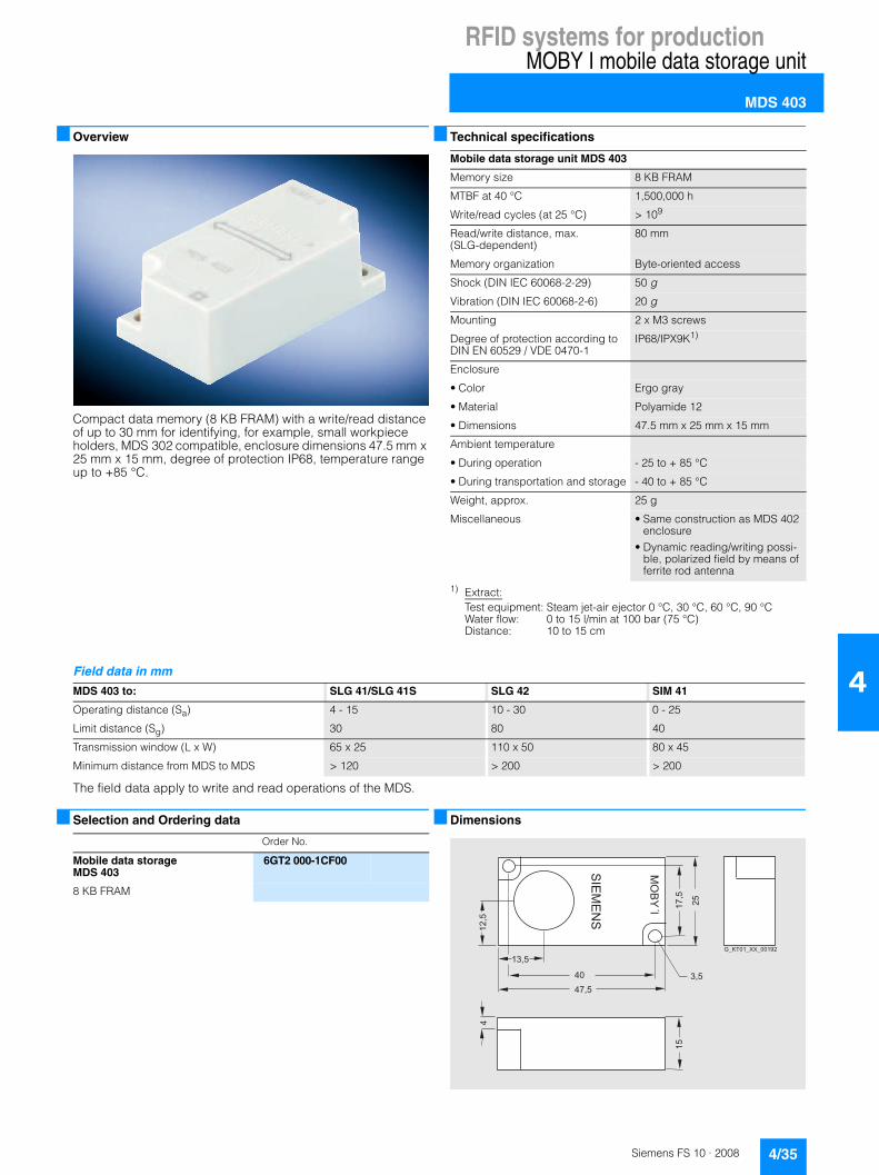
Compact data memory (8 KB FRAM) with a write/read distance of up to 30 mm for identifying, for example, small workpiece holders, MDS 302 compatible, enclosure dimensions 47.5 mm x 25 mm x 15 mm, degree of protection IP68, temperature range up to +85 °C.
■ Technical specifications
1) Extract:Test equipment: Steam jet-air ejector 0 °C, 30 °C, 60 °C, 90 °CWater flow: 0 to 15 l/min at 100 bar (75 °C)Distance: 10 to 15 cm
The field data apply to write and read operations of the MDS.
■ Selection and Ordering data
■ Dimensions
Mobile data storage unit MDS 403
Memory size 8 KB FRAM
MTBF at 40 °C 1,500,000 h
Write/read cycles (at 25 °C) > 109
Read/write distance, max.(SLG-dependent)
80 mm
Memory organization Byte-oriented access
Shock (DIN IEC 60068-2-29) 50 g
Vibration (DIN IEC 60068-2-6) 20 g
Mounting 2 x M3 screws
Degree of protection according to DIN EN 60529 / VDE 0470-1
IP68/IPX9K1)
Enclosure
• Color Ergo gray
• Material Polyamide 12
• Dimensions 47.5 mm x 25 mm x 15 mm
Ambient temperature
• During operation - 25 to + 85 °C
• During transportation and storage - 40 to + 85 °C
Weight, approx. 25 g
Miscellaneous • Same construction as MDS 402 enclosure
• Dynamic reading/writing possi-ble, polarized field by means of ferrite rod antenna
Field data in mm
MDS 403 to: SLG 41/SLG 41S SLG 42 SIM 41
Operating distance (Sa) 4 - 15 10 - 30 0 - 25
Limit distance (Sg) 30 80 40
Transmission window (L x W) 65 x 25 110 x 50 80 x 45
Minimum distance from MDS to MDS > 120 > 200 > 200
Order No.
Mobile data storage MDS 403
6GT2 000-1CF00
8 KB FRAM
"!#�#$"
�����% �
��
�,��
���
��
���
�
��
,�
�������������;,
��

RFID systems for productionMOBY I mobile data storage unit
MDS 404
4/36 Siemens FS 10 · 2008
4
■ Overview
Data memory for universal applications (8 KB FRAM), enclosure dimensions 50 mm x 50 mm x 20 mm, degree of protection IP68, temperature range up to +70 °C/momentarily +85 °C.
■ Technical specifications
1) Extract:Test equipment: Steam jet-air ejector 0 °C, 30 °C, 60 °C, 90 °CWater flow: 0 to 15 l/min at 100 bar (75 °C)Distance: 10 to 15 cm
The field data apply to write and read operations of the MDS.
■ Selection and Ordering data
■ Dimensions
Mobile data storage unit MDS 404
Memory size 8 KB FRAM
MTBF (at 40 °C) 1,500,000 h
Battery Without battery
Write/read cycles > 109
Read/write distance, max.(SLG-dependent)
90 mm
Memory organization Byte-oriented access
Shock (DIN IEC 60068-2-29) 50 g
Vibration (DIN IEC 60068-2-6) 20 g
Mounting 2 x M4 screws
Degree of protection according to DIN EN 60529 / VDE 0470-1
IP68/IPX9K1)
Enclosure
• Dimensions (mm) 50 x 50 x 20
• Color/material Ergo gray/polyamide 12
Ambient temperature
• During operation -25 to +70 °C
• During transportation and storage -40 to +70 °C
Weight 50 g
Field data in mm
MDS 404 to: SLG 41/SLG 41S SLG 42 SLG 43 SIM 41
Operating distance (Sa) 0 - 12 0 - 30 0 - 50 0 - 20
Limit distance (Sg) 25 60 90 33
Transmission window
• L: vertical 36 90 140 60
• 2L: horizontal 72 180 260 80
Minimum distance from MDS to MDS > 90 > 250 > 500 > 200
Order No.
Mobile data storage MDS 404
6GT2 000-0EG00
8 KB FRAM, with fixing frame
�65
���� ��
?
,�;
�
��
��
���
��
''"($%@�&��1��*
�."��65�#���$"�( )�!"&�)'��*!."�( )�!��*�2��("����!."�'. 1�(���"��
� )�!��*�2��("
���
����������;

RFID systems for productionMOBY I mobile data storage unit
MDS 506
4/37Siemens FS 10 · 2008
4
■ Overview
Data memory for universal applications (32 KB FRAM), enclo-sure dimensions 75 mm x 75 mm x 40 mm, degree of protection IP68, temperature range up to 70 °C.
■ Technical specifications
The field data apply to write and read operations of the MDS.
■ Selection and Ordering data
■ Dimensions
Mobile data storage unit MDS 506
Memory size 32 KB FRAM
MTBF (without battery, at 40 °C) 1,500,000 h
Write/read cycles > 109
Read/write distance, max.(SLG-dependent)
150 mm
Memory organization Byte-oriented access
Shock (DIN IEC 60068-2-29) 50 g
Vibration (DIN IEC 60068-2-6) 20 g
Mounting 2 x M5 screws
Degree of protection according to DIN EN 60529 / VDE 0470-1
IP68
Enclosure
• Dimensions (mm) 75 x 75 x 40
• Color/material Ergo gray/polyamide 12
Ambient temperature
• During operation -25 to +70 °C
• During transportation and storage -40 to +70 °C
Weight, approx. 200 g
Field data in mm
MDS 506 to: SLG 42 SLG 43 SIM 41
Operating distance (Sa) 10 - 35 20 - 100 0 - 25
Limit distance (Sg) 70 150 40
Transmission window
• L: vertical 120 220 85
• 2L: horizontal 190 400 100
Minimum distance from MDS to MDS > 300 > 600 > 300
Order No.
Mobile data storage MDS 506
6GT2 000-0DC00-0AA0
32 KB FRAM
�������������
��
����
�
�
���

RFID systems for productionMOBY I mobile data storage unit
MDS 514
4/38 Siemens FS 10 · 2008
4
■ Overview
Data memory for universal applications (32 KB FRAM), enclo-sure dimensions 50 mm x 50 mm x 20 mm, degree of protection IP68/IPX9K 1), temperature range up to +85 °C.1) Extract:
Test equipment: Steam jet-air ejector 0 °C, 30 °C, 60 °C, 90 °CWater flow: 0 to 15 l/min at 100 bar (75 °C)Distance: 10 to 15 cm
■ Technical specifications
The field data apply to write and read operations of the MDS.
■ Selection and Ordering data
■ Dimensions
Mobile data storage unit MDS 514
Memory size 32 KB FRAM
MTBF (at 40 °C) 1,500,000 h
Write/read cycles > 109
Read/write distance, max. (SLG-dependent)
90 mm
Memory organization Byte-oriented access
Shock (DIN IEC 60068-2-29)
50 G
Vibration (DIN IEC 60068-2-6)
20 G
Mounting 2 x M4 screws
Degree of protection IP68/IPX9K1)
Enclosure
• Dimensions 50 mm x 50 mm x 20 mm
• Color/material Ergo gray/polyamide 12
Ambient temperature
• During operation -25 to +85 °C
• During transportation and storage -40 to +85 °C
Weight 50 g
Field data in mm
MDS 514 to: SLG 41/SLG 41S SLG 42 SLG 43 SIM 41
Operating distance (Sa) 0 - 12 0 - 30 0 - 50 0 - 20
Limit distance (Sg) 25 60 90 33
Transmission window
• L: vertical 36 90 140 60
• 2L: horizontal 72 180 260 80
Minimum distance from MDS to MDS > 90 > 250 > 500 > 200
Order No.
Mobile data storage MDS 514
6GT2 000-0DG10
32 KB FRAM, with fixing frame
�65
���� ��
?
,�;
�
��
��
���
��
''"($%@�&��1��*
�."��65�#���$"�( )�!"&�)'��*!."�( )�!��*�2��("����!."�'. 1�(���"��
� )�!��*�2��("
���
����������;

RFID systems for productionMOBY I mobile data storage unit
MDS 439E
4/39Siemens FS 10 · 2008
4
■ Overview
Typical applications:• Primer coat, cataphoresis with the associated drying furnaces• Top coat area with drying furnaces• Washing areas at temperatures > +85 °C
■ Technical specifications
The field data apply to write and read operations of the MDS.
Cyclic operation of the MDS at temperatures > +100 °C
At ambient temperatures between +110 °C and +220 °C, care must be taken to ensure that the internal temperature of the MDS does not exceed the critical threshold of +110 °C. Each heating phase must therefore be followed by a cooling phase. Some limit cycles are listed in the table below:
Mobile data storage unit MDS 439E
Memory size 8 KB FRAM
MTBF (at 40 °C) 2,500,000 h
Write/read cycles > 109
Read/write distance, max. (SLG-dependent)
125 mm
Memory organization Byte-oriented access
Shock (DIN IEC 60068-2-29) 50 G
Vibration (DIN IEC 60068-2-6) 5 G
Mounting By means of optional bracket
Degree of protection according to DIN EN 60529 / VDE 0470-1
IP68
Ex approval ATEX Zone 2G
Enclosure
• Dimensions in mm (excluding weld seam)
Ø 114 x 83
• Color/material Brown/PPS
Ambient temperature
• During operation -25 °C to +110 °C/+220 °C cyclic
• During transportation and storage -40 to +110 °C
Weight without bracket 900 g
Field data in mm
MDS 439E to: SLG 42 SLG 43 SIM 41
Operating distance (Sa) 10 - 55 20 - 80 0 - 25
Limit distance (Sg) 70 125 33
Transmission window
• L: vertical 120 190 75
• 2L: horizontal 210 330 100
Minimum distance from MDS to MDS > 500 > 600 > 300
Cooling up Cooling down
Temperature Time Temperature Time
200 °C 2 h 25 °C > 8 h
200 °C 1 h 25 °C > 2 h
190 °C 2 h 25 °C > 7 h
190 °C 1 h 25 °C > 1 h 45 min
180 °C 2 h 25 °C > 5 h 30 min
170 °C 2 h 25 °C > 4 h 30 min

RFID systems for productionMOBY I mobile data storage unit
MDS 439E
4/40 Siemens FS 10 · 2008
4
■ Selection and Ordering data
A: Subject to export regulations AL = N and ECCN = EAR99H
■ Dimensions
Order No.
Mobile data storage unit MDS 439E
A 6GT2 000-0CD30-0AD0
8 KB FRAM
Accessories
Holder for MDS 439E
Short type A 6GT2 090-0QA00
Covering hood A 6GT2 090-0QB00
For skid support
�
��
��)��
��)��
)��
��)��
"!#�#$"
���)��*�
�+,��(����
&������'(��������������
;� ,�
��
,�
��� ���
5. �!�0"�'� ��8���,�;�?�A ��9
��!"���%+ B, �'.""!?("!�%�,���((�!.�#��C�,���6C���;�,�������
,
����
''"($%@
�!"����'�&" 2��65
E &�� �!� ��%8���,�;�?�A���9
���
���
�����
��;�

RFID systems for productionMOBY I write/read devices
Introduction
4/41Siemens FS 10 · 2008
4
■ Overview
The write/read device (SLG) provides inductive communication with the mobile data memories (MDS) and serial coupling to the communication modules (ASM).
A range of different SLGs are available for small, medium and large distances to the MDS meeting all customer requirements.
■ Function
The SLG implements the commands received from the commu-nication modules. These commands and the data to be written or read must be converted through an appropriate modulator/demodulator circuit.
The communication between MDS and SLG takes place over inductive alternating fields.
The transmittable quantity of information between SLG and MDS depends on:• the speed at which the MDS moves through the transmission
window of the SLG• the length of the transmission window
■ Technical specifications
Field data
Type Features
SLG 40S SLG with detached antenna (Ø 18 mm x 30 mm)e.g. for assembly lines with small workpiece holders• Max. read/write distance
8 mm• Degree of protection IP65 • Max. temperature: +70 °C
SLG 40 SLG with detached antenna (Ø 30 mm x 54 mm)e.g. for assembly lines with small workpiece holders• Max. read/write distance
10 mm• Degree of protection IP65 • Max. temperature: +70 °C
SLG 41 Universal compact SLG with rotating antenna head (BERO enclosure)• Max. read/write distance
30 mm• Enclosure dimensions (mm)
120 x 40 x 40 • Degree of protection IP65 • Max. temperature: +70 °C
SLG 41S Same as SLG 41, but with antenna rotated by 90°
SLG 42 Universal SLG• Max. read/write distance
70 mm• Enclosure dimensions (mm)
75 x 75 x 40 • Degree of protection IP65 • Max. temperature: +70 °C
SLG 43 Universal SLG• Max. read/write distance
150 mm• Enclosure dimensions (mm)
75 x 75 x 40 • Degree of protection IP65 • Max. temperature: +70 °C
SIM 41 Universal SLG with serial interface to PC/PLC• Max. read/write distance
40 mm• Enclosure dimensions (mm)
75 x 75 x 40 • Degree of protection IP54• Max. temperature: +70 °C
Minimum spacing from SLG to SLG in mm
SLG 40S > 50
SLG 40 > 50
SLG 41, SLG 41S 200
SLG 42 800
SLG 43 2000
SIM 41 700
Type Features

RFID systems for productionMOBY I write/read devices
SLG 40 / SLG 40S
4/42 Siemens FS 10 · 2008
4
■ OverviewSLG 40
Of particular benefit is the small mounting clearance between several SLG 40 antennas. The antenna head can be positioned very precisely for any application using the two screw nuts.
SLG 40S
Of particular benefit is the small mounting clearance between several SLG 40S antennas. The antenna head can be positioned very precisely for any application using the two screw nuts.
■ Application
The SLG 40 and the SLG 40S can be used to great advantage on small assembly lines.
■ Technical specifications
Read/write device SLG 40 SLG 40S
Inductive interface to the MDS
Transmission speed MDS to SLG Typically 0.8 ms/byte
Read/write distance max. 10 mm, see MDS field data max. 8 mm, see MDS field data
Transmission frequency (data/energy) 1.81 MHz/134 kHz
Distance SLG-to-SLG min. 50 mm
Special features Only one transmission field, centered over the antenna head
Serial interface to ASM RS-422, 6-pin SLG-connector to DIN 43651
Max. cable length (ASM-SLG) at 24 V DC max. 360 m
MTBF (at +40 °C) 2 x 10⁶ hours
Supply voltage
• Rated value 24 V DC
• Permissible range 20 V to 30 V DC
Current consumption
• No-load operation 25 mA
• Operation 90 mA
Casing
• Dimensions in mm
- Antenna head M30 x 1.5 x 54 M18 x 1,0 x 30
- Electronics without connector 125 x 40 x 75 75 x 75 x 40
• Color
- Antenna/SLG housing Anthracite with pastel turquoise head/ergo-gray
• Material
- Antenna/SLG housing Krastin/polyamide 12
Degree of protection according to DIN EN 60529 / VDE 0470-1 IP65
Shock (DIN IEC 60068-2-29) 50 G
Vibration (DIN IEC 60068-2-6) 20 G
Attachment of the SLG 4 screws
Ambient temperature
• During operation -25 °C to +70 °C
• During transportation and storage -40 °C to +85 °C
Weight, approx. 200 g 215 g

RFID systems for productionMOBY I write/read devices
SLG 40 / SLG 40S
4/43Siemens FS 10 · 2008
4
■ Selection and Ordering data
■ Dimensions
Write/read device SLG 40
Write/read device SLG 40S
Order No.
Write/read device forconnection to ASM
SLG 40S 6GT2 001-0EB00
Write/read device for connection to ASM, with separate antenna(Ø 18 mm x 30 mm)
SLG 40 6GT2 001-0EA10
Write/read device for connection to ASM, with separate antenna(Ø 30 mm x 54 mm)
Accessories
MOBY software 6GT2 080-2AA10
FB/FC for SIMATIC, 3964R driver for DOS/Windows 95/NT/2000/XP, C-libraries, PC presentation program, RFID documentation
���
���,�
���
����FC
��
�����FC
57����
57����
���
,�/%���0�"1� 2���!"����."�&
������� !"#!� ��'%""0"�#���$"�$"�!����%%�&��"#!� �'
����()(�$"�&��*��&�)'+�,��((
-�$%"�%"�*!.�����(
�!"����."�&
5#�"1��)!'
�!"����'�&"
���
����������;�
3��"�!.�"�&��4��� ���
�
��
�
�
�
��,�
��
����?C
57����<5,�
�
���
����������;
/%���0�"1� 2���!"����."�&
������� !"#!� ��'%""0"�#���$"�$"�!����%%�&��"#!� �'
����()(�$"�&��*��&�)'+�,��((
-�$%"�%"�*!.�����(
�!"����."�&
5#�"1��)!'
�!"����'�&"3��"�!.�"�&���4�

RFID systems for productionMOBY I write/read devices
SLG 41 / SLG 41S
4/44 Siemens FS 10 · 2008
4
■ Overview
SLG 41
The SLG 41 is a write/read device in the lower performance range. It can be used very effectively wherever the MDS carrier system (e.g. workpiece carrier) can be mechanically positioned with relative precision. Thanks to its swivel head (BERO enclo-sure), the SLG 41 can be adapted very well to the transport system.
In dynamic mode, only a small amount of data can be read or written between SLG 41 and the MDS.
SLG 41S
In contrast to the SLG 41, the antenna of the SLG 41S is rotated by 90 ° in the swivel head. This enables all positions of the trans-mission window to be implemented.
■ Technical specifications
■ Selection and Ordering data
■ Dimensions
Write/read device SLG 41 / SLG 41S
Inductive interface to the MDS
Transmission speed MDS to SLG Typically 0.8 ms/byte
Read/write distance max. 25 mm, see MDS field data
Transmission frequency (data/energy)
1.81 MHz/134 kHz
Distance SLG-to-SLG min. 200 mm
Special features BERO housing, swivel-mounted antenna head
Serial interface to ASM RS-422, 6-pin SLG-connector to DIN 43651
Max. cable length (ASM-SLG) at 24 V DC
360 m
MTBF (at +40 °C) 2 x 10⁶ hours
Supply voltage
• Rated value 24 V DC
• Permitted range 20 V to 30 V DC
Current consumption
• No-load operation 20 mA
• Operation 90 mA
Housing
• Dimensions (mm) 120 x 40 40
• Color Ergo gray
• Material Polyamide 12
Degree of protection to DIN EN 60529 / VDE 0470-1
IP65
Shock to DIN IEC 60068-2-29 50 g
Vibration to DIN IEC 60068-2-6 20 g
Fixing 4 screws
Tightening torque (at room temperature)
M5 ≤ 3 Nm
Ambient temperature
• Operating -25 °C to +70 °C
• During transportation and storage
-40 °C to +85 °C
Weight, approx. 210 g
Order No.
Write/read devicefor connecting to ASM
Write/read device SLG 41 6GT2 001-0AA00
Distributed applications in the low-end performance range
Write/read device SLG 41S 6GT2 001-0AA00-0AX0
Same as SLG 41, but with antenna rotated by 90°
Accessories
MOBY software 6GT2 080-2AA10
FB/FC for SIMATIC, 3964R driver for DOS/Windows 95/NT/2000/XP, C-libraries, PC presentation program, RFID documentation
�����
�����
��
��
��
����
�� ��
,�
,�
�;
�
����
��
����
�� ��
,�
,�
���;
�� �
����
57����5+
57����+
���
����������;�
/ '�!� �� 2��0 !�."�&1."�&"%�0"�"&
/ '�!� �� 2��0 !�."�&1."�&"%�0"�"&

RFID systems for productionMOBY I write/read devices
SLG 42
4/45Siemens FS 10 · 2008
4
■ Overview
The SLG 42 is a write/read device in the mid-performance range. Due to the larger antenna dimensions, the SLG 42 creates a much larger field than the SLG 41. This means that using the same data memories, a larger range can be achieved. In dynamic operation, larger quantities of data can be read/written by the MDS.
■ Technical specifications
■ Selection and Ordering data
■ Dimensions
Write/read device SLG 42
Inductive interface to the MDS
Transmission speed MDS to SLG Typically 0.8 ms/byte
Read/write distance max. 70 mm, see MDS field data
Transmission frequency (data/energy)
1.81 MHz/134 kHz
Distance SLG-to-SLG min. 800 mm
Serial interface to ASM RS422, 6-pin SLG-connector to DIN 43651
Max. cable length (ASM-SLG)at 24 V DC
max. 120 m
MTBF (at +40 °C) 2,000,000 h
Supply voltage
• Rated value 24 V DC
• Permitted range 20 V to 30 V DC
Current consumption
• No-load operation 60 mA
• Operation 180 mA
Housing
• Dimensions (mm) 75 x 75 x 40
• Color gray
• Material Polyamide 12
Degree of protection to DIN EN 60529 / VDE 0470-1
IP65
Shock to DIN IEC 60068-2-29 50 g
Vibration to DIN IEC 60068-2-6 20 g
Fixing 2 screws
Tightening torque (at room temperature)
M5 ≤ 2 Nm
Ambient temperature
• in operation -25 °C to +70 °C
• During transportation and storage -40 °C to +85 °C
Weight, approx. 250 g
Order No.
Write/read devices for connecting to ASM
Write/read device SLG 42 6GT2 001-0BA00
With TTY (20 mA current loop) interface
Accessories
CD "RFID Systems Software & Documentation"
6GT2 080-2AA10
FB/FC for SIMATIC, 3964R driver for DOS/Windows 95/NT/2000/XP, C-libraries, PC presentation program, RFID documentation
���
���
�44���
�;;
� �
�
��
���
���
�
�,�
�;

RFID systems for productionMOBY I write/read devices
SLG 43
4/46 Siemens FS 10 · 2008
4
■ Overview
The SLG 43 is a high-performance write/read device. A particu-lar advantage is that the device can be used with large MDS types (MDS 506/MDS 439E). An essential feature is the size of the transmission window. This compensates well for mechanical tolerances of the transport system. In dynamic mode, the large transmission window enables large quantities of data to be read or written.
■ Technical specifications
■ Selection and Ordering data
■ Dimensions
Write/read device SLG 43
Inductive interface to the MDS
Transmission speed MDS to SLG Typically 0.8 ms/byte
Read/write distance max. 150 mm, see MDS field data
Transmission frequency (data/energy)
1.81 MHz/134 kHz
Distance SLG-to-SLG > 2000 mm
Serial interface to ASM RS422, 6-pin SLG-connector to DIN 43651
Max. cable length (ASM-SLG) at 24 V DC
max. 85 m
MTBF (at +40 °C) 2,000,000 h
Supply voltage
• Rated value 24 V DC
• Permitted range 20 V to 30 V DC
Current consumption
• No-load operation 60 mA
• Operation 250 mA
Housing
• Dimensions (mm) 238 x 40 x 80
• Color Ergo gray
• Material Polyamide 12
Degree of protection to DIN EN 60529 / VDE 0470-1
IP65
Shock to DIN IEC 60068-2-29 50 g
Vibration to DIN IEC 60068-2-6 20 g
Fixing 4 screws
Ambient temperature
• in operation -25 °C to +70 °C
• During transportation and storage -40 °C to +85 °C
Weight, approx. 800 g
Order No.
Write/read devicefor connecting to ASM:
Write/read device SLG 43 6GT2 001-0CA10
With TTY (20 mA current loop) interface
Accessories
CD "RFID Systems Software & Documentation"
6GT2 080-2AA10
FB/FC for SIMATIC, 3964R driver for DOS/Windows 95/NT/2000/XP, C-libraries, PC presentation program, RFID documentation
���
����44���,��
,�,
�
,�
,,�
���
,� �;
������
��

RFID systems for productionMOBY I write/read devices
SIM 41
4/47Siemens FS 10 · 2008
4
■ Overview
The SIM module is a write/read device with integral antenna and serial interface for connection to the following systems:• Computer• PC• PLCs
A rugged housing supports use under harsh conditions and makes the MDS resistant to many chemical substances.
■ Function
The SIM combines a communications module (ASM) and a write/read device (SLG) in one enclosure with V.24 (RS232) interface.
It can be operated by means of various procedures (3964R, Lauf, SINEC L1 and SINUMERIK protocol).
For quick and easy integration into the application (PC with Windows 98/NT), the C library MOBY API (included on the CD "RFID Systems Software & Documentation") is available with the MOBY basic functions (read, write, etc.).
Configurator
■ Technical specifications
���
���������,��
�?# (���/-
,��B�6-
5C�
�65
Serial Interface Module SIM 41
Inductive interface to the MDS
Data transmission rate Typically 0.8 ms/byte
For read/write distance, see MDS field data
max. 40 mm, see MDS field data
max. transmission frequency (data/energy)
1.81 MHz/134 kHz
Serial interface 25-pin sub D connector (pin) with interlocking screw
Data transmission rate 2400 to 9600 baud
Max. cable length V.24: 30 m (shielded)
Software functions Read, write, initialize MDS, set MDS type ...
Programming Dependent on computer, PC
Available software (included on MOBY software CD)
MOBY API for Windows 98/NT 4.0, 3964R driver for DOS
Digital inputs
Quantity 2
Electrical isolation no
Input voltage
• For logical “0” -2 V to +5 V
• For logical “1” +12 V to +33 V (Ri = 10 kΩ)
Delay time < 10 ms
Digital outputs
Quantity 2
Electrical isolation No, (internal voltage supply) short-circuit-proofImax = 200 mA(per DO, or for 2 DOs)
Power supply
• Rated value 24 V DC
• Permissible range 20 to 30 V DC
Current consumption max. 220 mA (DO with no load)
Shock to DIN IEC 60068-2-29 30 g
Degree of protection according to DIN EN 60529 / VDE 0470-1
IP54
Ambient temperature
• During operation 0 °C to +60 °C
• During transportation and storage -20 °C to +70 °C
Dimensions (mm) 75 x 75 x 40
Weight, approx. 0.3 kg

RFID systems for productionMOBY I write/read devices
SIM 41
4/48 Siemens FS 10 · 2008
4
■ Selection and Ordering data
A: Subject to export regulations AL = N and ECCN = EAR99H
■ Dimensions
Order No.
Write/read device for direct connection to the PC or PLC
Write/read device SIM 41 A 6GT2 005-0AA10
with V.24 (RS 232) interface
Accessories
CD: "RFID Systems Software & Documentation"
6GT2 080-2AA10
FB/FC for SIMATIC, 3964R driver for DOS/Windows 95/NT/2000/XP, C-libraries, PC presentation program, RFID documentation
���
����44���,�,
,�
�
�
�
��
�
��
���
�
����

RFID systems for productionMOBY I write/read devices
STG I mobile handheld terminal
4/49Siemens FS 10 · 2008
4
■ Overview
The STG I is a powerful mobile handheld terminal with integral write/read antenna for applications in the field of logistics, distri-bution and service. In addition, it is an indispensable tool for commissioning and testing.
■ Design
The STG I mobile handheld terminal consists of one basic unit (Basis PSION Workabout PRO) and a removable compact read/write head. It has a splash water-proof enclosure (IP54), LCD color monitor 1/4 VGA, 320 x 240 pixels, TFT portrait format, alphanumeric keyboard and various interfaces (for SD memory card, charging batteries, USB, Bluetooth, etc.).
■ Function
The pre-installed MOBY software provides service and test functions for reading, writing, etc. of the MOBY data memory:• Reading data from the data memory • Writing data to the data memory • Reading and displaying the ID number of the data memory
(to the extent available)• Displaying and editing the data in hexadecimal, ASCII,
decimal and binary formats • Activate/deactivate password• MOBY file handler
User applications that were developed for the predecessor model Workabout MX can be transferred to this terminal with little effort. For this purpose, various optional development tools for the PC are available directly from PSION. This is opening up new applications in the field of logistics and distribution, for example, the handheld terminal enables commissioning data to be recorded or processed offline and forwarded to the PC/computer with a time delay.
■ Technical specifications
STG I mobile handheld terminal
Processor 400 MHz Intel Xscale PXA255
Operating system Microsoft Windows CE .NET 4.20
RAM/Flash EEPROM memory 128 MB/32 MB
User program MOBY standard application
Screen TFT color touch display , ¼ VGA 320 x 240 (portrait format); adjust-able backlighting
Keyboard alphanumeric
Sound Piezo signal transmitter
Power supply • Lithium-ion battery(3.7 V; 3000 mAh)
• Quick charging possible (automatic shut-off) or 3 x 1.5 V type AA
• Backup battery: 3 V ML 2032 lithium cell
Interfaces • LIF interface (low insertion force interface) for battery charging and communication with the PC using a docking and loading station (USB)
• CF interface for expansion cards (e.g. WLAN)
Dimensions 305 x 90 x 44 [mm]
Weight (incl. battery) Approx. 0.5 kg
Ambient temperature
• During operation -10 °C ...+50 °C
• Storage (without batteries) -25 °C ...+60 °C
Relative humidity, non-condensing 5 ... 90 %
Degree of protection IP54 (splash water proof)
EMC EN 55022, EN 55024
Integral read/write head, inductive interface to MDS
for MOBY I
Read/write distance to MDS up to 20 mm, depending on MDS
Energy/data transmission frequency 134 kHz/1.81 MHz
Serial interface (to basic unit) TTL, 3964R protocol
Functionality of the SW application Standard user interface for read-ing/writing of data memories, etc.

RFID systems for productionMOBY I write/read devices
STG I mobile handheld terminal
4/50 Siemens FS 10 · 2008
4
■ Selection and Ordering data
A: Subject to export regulations AL = N and ECCN = EAR99H
D: Subject to export regulations AL = N and ECCN = 4A994
■ Accessories
For optional components, please visit http://www.psionteklogix.com
For example:• SD expansion cards• Handles, belt loops• Vehicle holder with charging function
Order No.
Mobile handheld terminal STG I with MOBY I write/read head
D 6GT2 003-0CA10
Basic unit (PSION Workabout PRO) with MOBY I read/write, bat-tery, standard software pre-installed, without loading/dock-ing station
Accessories
Loading/docking station A 6GT2 898-0BA00
For a mobile handheld terminal as well as a spare battery, incl. wide-range plug-in power supply 100 ... 240 V AC and country-specific adaptersas well as USB cable
MOBY I write/read head 6GT2 003-1CA00
For basic unit (PSION Workabout mx and PSION Workabout PRO)
Basic unit D 6GT2 003-0AA10
Basic unit (PSION Workabout PRO) with adapter for MOBY RFID read/write heads
Spare battery A 6GT2 898-0CA00
For basic unit (PSION Workabout PRO), High Capacity 3000 mAh, Li-ion
CD: "RFID Systems Software & Documentation"
6GT2 080-2AA10
FB/FC for SIMATIC, 3964R driver for DOS/Windows 95/NT/2000/XP, C libraries, PC presentation program. MOBY documentation

RFID systems for productionMOBY I
Configuring instructions
4/51Siemens FS 10 · 2008
4
■ Overview
Configuring note
Detailed configuration and commissioning data is contained in the “Manual for Configuration, Assembly and Service”. For ordering data, refer to “Documentation”.
Transmission window
The write/read device generates an inductive alternating field. The field is at its strongest near the SLG and declines rapidly as the distance from the SLG increases. The distribution of the field depends on the structure and geometry of the antennas in the write/read device and MDS.
A prerequisite for the function of the MDS is a minimum field strength at the MDS that is achieved at a distance Sg from the write/read device. The drawing below shows the transmission window between MDS and SLG.
M: Center point of the transmission window
Sa: Operating range
Sg: Limit distance (maximum clear distance between upper sur-face of SLG and upper surface of MDS, at which the trans-mission can still function under normal conditions)
L: Length of a transmission window for vertical motion of the MDS
2L: Length of a transmission window for horizontal motion of the MDS
UL: The transmission gap lies between the two transmission windows. In this area it is not possible to work with the MDS. The transmission gap is a few millimeters long. In all further analyses, the UL is not taken into account (UL = 0 mm)
Representation of speed relative to data quantity
The characteristics shown should make it easier to preselect the MOBY I components MDS and SLG for dynamic use. The char-acteristics apply for vertical operation with single length of the transmission window (L) and the operating distance (Sa).
Example SLG 41
Example for SLG 42 (vertical operation)
Example for SLG 43 (vertical operation)
���
���������,�
��������
�������
�65
,7�7
7
*55�� �
57�
,7
7
� �
��4��!���'(�''� ��1��& 1�!����� 4���<,�5
����'(�''� ��1��& 1��!�5
�
�
57�
7
�
��
��
��
���
���
�
����� �� �� ����
����
�
�� �� �� �� �� �� �� �� ���
�����
���
���
��������
�
�������� ��!"��
����� ��������#�$% &��"��
�'��
�'��
�'��
�'��
�
��
��
���
����
���
�
����� �� �� ����
������ �� �� �� �� �� �� �� ��
���
����
��
���
���
��������
�
�
�
�'�
�'�
�
�
�'��
�'�
�
�������#�$% &��"��
�����
������ ��������#�$% &��"��
�������� ��!"��
��
����� �� �� ����
������ �� �� ��� ��� ��� ��� ��� ���
��
��
��
���
���
���
���
���
���
���
���������
�������� ��!"��
������ ��������#�$% &��"��
�������#�$% &��"��
�'�
�
�
�'�
�
�'�
�
�'��
�

RFID systems for productionSIMATIC RF300
Introduction
4/52 Siemens FS 10 · 2008
4
■ Overview
SIMATIC RF 300 is a non-contact identification system specially designed for use in industrial production for the control and optimization of the material flow. Thanks to its compact modular structure, it is particularly suited for small assembly lines and conveyor systems with restricted space for installation. The rug-ged components feature an attractive price/performance ratio.
Depending on the demands on the identification system, two versions of the system are available:• A particularly economical solution with a link to SIMATIC S7-
300 over the IQ-Sense interface for low requirements in terms of speed and data volume
• Write/read devices for high demands in terms of speed and data volume for connection to SIMATIC, PROFIBUS, PC or non-Siemens controllers (available soon)
The SIMATIC RF300 identification system boasts the following features:• 13.56 MHz operating frequency• Passive (without battery) transponders (tags)• Rugged, compact components• Very high immunity to noise• Extensive diagnostic functions• Extremely fast data transmission (except for IQ-Sense
interface)• Simple integration into SIMATIC and the PROFIBUS DP
■ Benefits
Minimization of commissioning time by direct connection of system to S7-300, PROFIBUS, Ethernet and non-Siemens PLC or PC.
Minimization of downtimes thanks to:• Fault-resistant data transmission • Specific diagnostics information• High data security under critical operating conditions
High-speed data processing thanks to high data transmission rates on the "air interface".
SIMATIC RF300 records the data of objects quickly and reliably. SIMATIC RF300 thereby ensures effective and cost-effective automation.
■ Application
The RFID system SIMATIC RF300 is used primarily for contact-free identification of containers, pallets and workpiece holders in a closed production cycle. This means that the data carriers (transponders, tags) remain in the production chain and are not shipped out with the products. Thanks to the compact enclosure dimensions of the transponders as well as of the write/read devices, SIMATIC RF300 is particularly suitable for (small) as-sembly lines where space is at a premium.
The main application areas of SIMATIC RF300 are:• Assembly and handling systems, assembly lines
(identification of workpiece carriers)• Production logistics (material flow control, identification of
containers and other vessels)• Parts identification (e.g. transponder is attached to product or
pallet)• Conveyor systems (e.g. overhead monorail conveyors)
■ Function
The MOBY and SIMATIC RF300 RFID systems ensure that highly-informative data accompany a product right from the start.
Tags ("electronic delivery notes") are used in place of barcodes and contain all production-specific data in addition to the prod-uct number. Up to 32 KB of user data can be stored and man-aged in this way. Enough to enable quality data to be stored as well.
Using stationary as well as mobile read/write devices, the nec-essary information (production data, transport routes, etc.) can be read from the tag without contact (inductively) and can even be added to or modified without the need for a direct line-of-sight link.

RFID systems for productionSIMATIC RF300
Introduction
4/53Siemens FS 10 · 2008
4
■ Technical specifications
Type Contactless, inductive RF identification system for industrial applications
Transmission frequency data/energy 13.56 MHz
Memory capacity • 20 byte to 64 KB user memory (r/w)
• 4 byte fixed code as serial number (ro)
Memory type EEPROM / FRAM
Write cycles EEPROM: > 100 000FRAM: unlimited
Read cycles unlimited
Data management Byte-oriented access
Data transmission rate from mobile data storage unit to read/write device
3 KB/s (IQ-Sense: 50 byte/s)
Write/read distance (system limit) Up to 150 mm
Operating temperature Reader: -25 °C to +70 °CTag: -40 °C to +85 °C
Degree of protection Reader: IP65 to IP67Tag: IP67 to IPx9K
Can be connected to • SIMATIC S7-300• PROFIBUS DP V1• PROFINET• PC• Non-Siemens PLC
Special features • High noise immunity• Compact components• Extensive diagnostic options• Reader with IQ-Sense interface
Approvals • ETS 300330 (Europe)• FCC Part 15 (USA) • UL/CSA CE

RFID systems for productionSIMATIC RF300 mobile data storage unit
Introduction
4/54 Siemens FS 10 · 2008
4
■ Overview
1) Extract:Test equipment: Steam jet-air ejector 0 °C, 30 °C, 60 °C, 90 °CWater flow: 0 to 15 l/min at 100 bar (75 °C)Distance: 10 to 15 cm
■ Design
A SIMATIC RF 300 data storage unit essentially consists of an electronic module, an antenna and an EEPROM or FRAM memory built into a rugged plastic enclosure.
■ Function
If a tag moves into the transmission field of the reader, the necessary power for all circuit components is generated and monitored by means of the energy supply unit. The pulse-coded information is prepared in such a way that it can be processed further as pure digital signals. The handling of data, including check routines, is performed by the control unit which also manages the user memory.
Type Features
SIMATIC RF320T Universal, compact data storage unit (20 + 4 byte EEPROM)∅ 27 mm x 4 mm, not suitablefor mounting directly on metal • Degree of protection
IP67/IPX9K1)
• Temperature range up to +85 °C
SIMATIC RF340T Universal data storage unit(8 KB FRAM + 24 byte EEPROM), 48 mm x 25 mm x 15 mm • Degree of protection
IP68/IPX9K1)
• Temperature range up to +85 °C
SIMATIC RF350T Universal data storage unit(32 KB FRAM + 24 byte EEPROM), 50 mm x 50 mm x 20 mm • Degree of protection IP68 • Temperature range up to +85 °C
SIMATIC RF360T Universal data storage unitin credit card format(8 KB FRAM + 24 byte EEPROM), 85.5 mm x 54.1 mm x 2.5 mm • Degree of protection IP67 • Temperature range up to +75 °C
SIMATIC RF370T Universal data storage unit (32 or 64 KB FRAM + 24 byte EEPROM), 75 mm x 75 mm x 40 mm • Degree of protection IP68 • Temperature range up to +85 °C
SIMATIC RF380T Heat-resistant data memory, designed for skid identificationin paint shops(32 KB FRAM + 24 byte EEPROM), housing dimensions (mm) Ø 114 x 83 • Degree of protection IP68 • Temperature range up to +220 °C
(cyclic)

RFID systems for productionSIMATIC RF300 mobile data storage unit
SIMATIC RF320T
4/55Siemens FS 10 · 2008
4
■ Overview
Universal, compact tag (20 + 4 byte EEPROM) in button format (Ø 27 mm x 4 mm), not suitable for mounting directly on metal.
■ Technical specifications
1) Extract:Test equipment: Steam jet-air ejector 0 °C, 30 °C, 60 °C, 90 °CWater flow: 0 to 15 l/min at 100 bar (75 °C)Distance: 10 to 15 cm
Field data in mm
■ Selection and Ordering data
A: Subject to export regulations AL = N and ECCN = EAR99H
■ Dimensions
Mobile data storage unit SIMATIC RF320T
Memory size 20 byte EEPROM (r/w),4 byte UID (ro)
MTBF 2,500,000 h
Read cycles Unlimited
Write cycles, min. 50 000
at ≤ 40 °C, typical > 1 000 000
Data retention time > 10 years (at < +40 °C)
Write/read distance (see field data)
Memory organization Byte-oriented access, write pro-tection possible in 4-byte blocks
Energy source Inductive power transmission
Shock/vibration to EN 60721-3-7, Class 7 M3
100 g/20 g
Torsion and bending load Not permissible
Mounting Adhesive/M3 screws
Recommended distance to metal ≥ 10 mm
Degree of protection to
• EN 60529 IP67
• DIN EN 60529 / VDE 0470-1 IPX9K1)
Enclosure Button
• Dimensions Ø 27 mm x 4 mm
• Color/material Black/epoxy resin
Ambient temperature
• During operation -25 ... +85 °C
• During transportation and storage -40 ... +125 °C
Weight, approx. 5 g
Mobile data storage unit SIMATIC RF320T
SIMATIC RF320T to: SIMATIC RF310R SIMATIC RF340R SIMATIC RF350R with ANT 1
SIMATIC RF350R with ANT 18
SIMATIC RF350R with ANT 30
Operating distance (Sa) 1 ... 10 1 ... 20 1 ... 20 0 ... 8 0 ... 11
Limit distance (Sg) 16 25 25 10 15
Transmission window (L) 30 45 45 10 15
Order No.
SIMATIC RF320T tag A 6GT2 800-1CA00
�
�������������
� ��
��
�
��

RFID systems for productionSIMATIC RF300 mobile data storage unit
SIMATIC RF340T
4/56 Siemens FS 10 · 2008
4
■ Overview
Universal data memory (8 KB FRAM + 24 byte EEPROM + 4 byte serial number), particularly suitable for small workpiece carriers.
■ Technical specifications
1) Extract:Test equipment: Steam jet-air ejector 0 °C, 30 °C, 60 °C, 90 °CWater flow: 0 to 15 l/min at 100 bar (75 °C)Distance: 10 to 15 cm
Field data in mm
■ Selection and Ordering data
A: Subject to export regulations AL = N and ECCN = EAR99H
■ Dimensions
Mobile data storage unit SIMATIC RF340T
Memory size 8 KB FRAM (r/w), 20 byte EEPROM (r/w), 4 byte UID (ro)
MTBF 1500000 h
Read cycles Practically unlimited (>1010)
Write cycles Practically unlimited (>1010)
Data retention time > 10 years (at < +40°C)
Write/read distance (see field data)
Memory organization Byte-oriented access, write protection possible in 4-byte blocks for the 20-byte EEPROM area
Energy source Inductive power transmission
Shock/vibration to EN 60721-3-7, 50 g / 20 g
Torsion and bending load Not permissible
Mounting 2 x M3 screws
Degree of protection to
• EN 60529 IP67/IPX9K1)
Dimensions in mm 48 x 25 x 15
Color/material Anthracite/polyamide 12
Ambient temperature
• During operation -25 to +85 °C
• During transportation and storage -40 to +85 °C
Weight, approx. 25 g
SIMATIC RF340T to: SIMATIC RF310R SIMATIC RF340R SIMATIC RF350R with ANT 1
SIMATIC RF350R with ANT 18
SIMATIC RF350R with ANT 30
Operating distance (Sa) 1 to 20 2 to 25 2 to 25 0 to 10 0 to 15
Limit distance (Sg) 26 35 35 13 20
Transmission window (L) 38 60 60 20 25
Order No.
SIMATIC RF340T tag A 6GT2 800-4BB00
�����
���
���
��
�
��
,�
35��������,
������
����
���

RFID systems for productionSIMATIC RF300 mobile data storage unit
SIMATIC RF350T
4/57Siemens FS 10 · 2008
4
■ Overview
Universal data memory (32 KB FRAM + 24 byte EEPROM)
■ Technical specifications
Field data in mm
-: Combination reader tag not released
■ Selection and Ordering data
A: Subject to export regulations AL = N and ECCN = EAR99H
Left: Mobile data memory.Upper right: Mounting frame.
Lower right: Installation diagram.The MDS can be mounted with the mounting frame as shown.
■ Dimensions
Mobile data storage unit SIMATIC RF350T
Memory size 32 KB FRAM (r/w), 20 bytes EEPROM (r/w), 4 bytes UID (ro)
MTBF 1500000 h
Read cycles Practically unlimited (>1010)
Write cycles Practically unlimited (>1010)
Data retention time > 10 years (at < +40°C)
Read/write distance (see field data)
Memory organization Byte-oriented access, write protection possible in 4-byte blocks for the 20-byte EEPROM area
Energy source Inductive power transmission
Shock/vibration to EN 60721-3-7, Class 7 M3
50 g/20 g
Torsion and bending load Not permissible
Fixing 2 x M4 screws
Recommended distance to metal Can be directly mounted onto metal
Degree of protection to EN 60529 IP68
Housing 8-sided, with fixing frame
L x W x H, in mm 50 x 50 x 20
Color/material Anthracite/polyamide 12
Ambient temperature
• During operation -25 to + 85 °C
• During transportation and storage -40 to +85 °C
Weight, approx. 25 g
SIMATIC RF350T to: SIMATIC RF310R SIMATIC RF340R SIMATIC RF350R with ANT 1
SIMATIC RF350R with ANT 18
SIMATIC RF350R with ANT 30
Operating distance (Sa) 2 to 22 5 to 35 5 to 35 - 0 to 16
Limit distance (Sg) 30 50 50 - 22
Transmission window (L) 45 60 60 - 25
Order No.
SIMATIC RF350T tag A 6GT2 800-5BD00
�65
���� ��
�;
;
�
;
��
��
���
��
35����
����,�

RFID systems for productionSIMATIC RF300 mobile data storage unit
SIMATIC RF360T
4/58 Siemens FS 10 · 2008
4
■ Overview
Universal data memory in credit card format (8 KB FRAM + 24 byte EEPROM).
■ Technical specifications
Field data in mm
-: Combination reader tag not released
■ Selection and Ordering data
A: Subject to export regulations AL = N and ECCN = EAR99H
■ Dimensions
Mobile data storage unit SIMATIC RF360T
Memory size 8 KB FRAM (r/w), 20 bytes EEPROM (r/w), 4 bytes UID (ro)
MTBF 1500000 h
Read cycles Practically unlimited (>1010)
Write cycles Practically unlimited (>1010)
Data retention time > 10 years (at < +40°C)
Read/write distance (see field data)
Memory organization Byte-oriented access, write protec-tion possible in 4-byte blocks for the 20-byte EEPROM area
Energy source Inductive power transmission
Shock/vibration to EN 60721-3-7 50 g/20 g
Torsion and bending load Not permissible
Fixing 2 screws M3 or with fixing lug 6GT2190-0AB00
Recommended distance to metal > 20 mm; e.g. using spacer 6GT2190-0AA00 in conjunction with fixing lug 6GT2190-0AB00
Degree of protection to EN 60529 IP68
Housing Credit card format
L x W x H, in mm 85.8 x 54.8 x 2.5
Color/material Anthracite / epoxy resin
Ambient temperature
• During operation -25 to +75 °C
• During transportation and storage -40 to +85 °C
Weight, approx. 25 g
SIMATIC RF360T to: SIMATIC RF310R SIMATIC RF340R SIMATIC RF350Rwith ANT 1
SIMATIC RF350R with ANT 18
SIMATIC RF350R with ANT 30
Operating distance (Sa) 2 to 26 8 to 40 8 to 40 - -
Limit distance (Sg) 35 60 60 - -
Transmission window (L) 45 70 70 - -
Order No.
SIMATIC RF360T tag A 6GT2 800-4AC00
Accessories
Fixing lug 6GT2 190-0AB00
For SIMATIC RF360T
Spacers 6GT2 190-0AA00
For fixing lug, thickness 20 mm The purpose of the spacer is to maintain the recommended dis-tance to the metal when installing the tag.
60
FS10_XX_00235
85,8
54,1
2,
5
R3
3,2

RFID systems for productionSIMATIC RF300 mobile data storage unit
SIMATIC RF370T
4/59Siemens FS 10 · 2008
4
■ Overview
Universal data storage unit in square format (32 or 64 KB FRAM + 24 byte EEPROM), 75 mm x 75 mm x 40 mm.
■ Technical specifications
Field data in mm
-: Combination reader tag not released
■ Selection and Ordering data
A: Subject to export regulations AL = N and ECCN = EAR99H
■ Dimensions
Mobile data storage unit SIMATIC RF370T
Memory size 32 or 64 KB FRAM (r/w), 20 byte EEPROM (r/w), 4 byte UID (ro)
MTBF 107 h
Read cycles Practically unlimited (>1010)
Write cycles Practically unlimited (>1010)
Data retention time > 10 years (at < +40°C)
Read/write distance (see field data)
Memory organization Byte-oriented access, write protection possible in 4-byte blocks for the 20-byte EEPROM area
Energy source Inductive power transmission
Shock/vibration to EN 60721-3-7, Class 7 M3
50 g/20 g
Torsion and bending load Not permissible
Fixing 2 M5 screws
Recommended distance to metal Can be directly mounted onto metal
Degree of protection to EN 60529 IP68
Housing Square format
L x W x H, in mm 75 x 75 x 40
Color/material Anthracite/polyamide 12
Ambient temperature
• During operation -25 to +85 °C
• During transportation and storage -40 to +85 °C
Weight, approx. 200 g
SIMATIC RF370T to: SIMATIC RF310R SIMATIC RF340R SIMATIC RF350Rwith ANT 1
SIMATIC RF350Rwith ANT 18
SIMATIC RF350R with ANT 30
Operating distance (Sa) - 15 ... 36 15 ... 45 - -
Limit distance (Sg) - 52 65 - -
Transmission window (L) - 75 70 - -
Order No.
SIMATIC RF370T tag A 6GT2 800-5BE00
With 32 KB FRAM
SIMATIC RF370T tag A 6GT2 800-6BE00
With 64 KB FRAM
41
FS
10_0
0237
75
75
75
5
5
Ø 5,2

RFID systems for productionSIMATIC RF300 mobile data storage unit
SIMATIC RF380T
4/60 Siemens FS 10 · 2008
4
■ Overview
Heat-resistant data memory, designed for skid identification in paint shops (32 KB FRAM + 24 byte EEPROM), housing dimensions (mm) Ø 114 x 83, temperature range up to +220 °C (cyclic).
■ Application
Typical applications are:• Primer application, cataphoresis with the associated drying
ovens • Outer paint coating area with drying ovens • Washing area with temperatures > +85 °C
■ Technical specifications
Field data in mm
-: Combination reader tag not released
■ Selection and Ordering data
A: Subject to export regulations AL = N and ECCN = EAR99H
SIMATIC RF380T
Memory size 32 KB FRAM (r/w), 20 byte EEPROM (r/w), 4 byte UID (ro)
MTBF 107 h
Read cycles Practically unlimited (>1010)
Write cycles Practically unlimited (>1010)
Data retention time > 10 years (at < +40 °C)
Write/read distance (see field data)
Memory organization Byte-oriented access, write protection possiblein 4-byte blocks for the 20-byte EEPROM area
Energy source Inductive power transmission
Shock/vibration to EN 60721-3-7 50 g/5 g
Torsion and bending load Not permissible
Mounting With special support (to be ordered separately)
Recommended distance to metal Can be directly mounted on metal
Degree of protection to EN 60529 IP68
Enclosure Round type
• Dimensions (Ø x H, in mm) 114 x 83
• Color/material Brown / PPS
Ambient temperature
• In operation (permanent) -25 to 110 °C
• In operation (cyclic) -25 to 220 °C
• During transportation and storage -40 to 110 °C
Weight, approx. 900 g
SIMATIC RF380T to: SIMATIC RF310R SIMATIC RF340R SIMATIC RF350R with ANT 1
SIMATIC RF350R with ANT 18
SIMATIC RF350Rwith ANT 30
Operating distance (Sa) - 15 to 47 15 to 53 - -
Limit distance (Sg) - 55 65 - -
Transmission window (L) - 86 70 - -
Order No.
SIMATIC RF380T tag A 6GT2 800-5DA00
With 32 KB FRAM
Accessories
Support for RF380T
• Short type A 6GT2 090-0QA00
• Long type A 6GT2 090-0QA00-0AX3
Shrouding cover A 6GT2 090-0QB00
For skid support
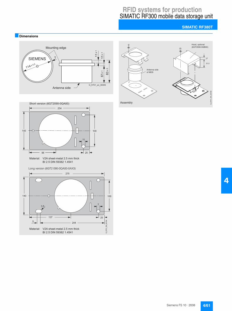
RFID systems for productionSIMATIC RF300 mobile data storage unit
SIMATIC RF380T
4/61Siemens FS 10 · 2008
4
■ Dimensions
�
��
��)��
��)��
)��
��)��
"!#�#$"
���)��*�
�+,��(����
&������'(��������������
;� ,�
��
,�
��� ���
� ,�
,�
��� ���
,���
��
5. �!�0"�'� ��8���,�;�?�A ��9
��!"���%+ B, �'.""!?("!�%�,���((�!.�#��C�,���6C���;�,�������
7 �*�0"�'� ��8���,�;�?�A ��?D �9
���
����������;�
��!"���%+ B, �'.""!?("!�%�,���((�!.�#��C�,���6C���;�,�������
Long version (6GT2 090-0QA00-0AX3)
,
����
''"($%@
�!"����'�&" 2��65
E &�� �!� ��%8���,�;�?�A���9
���
�����
�����;�

RFID systems for productionSIMATIC RF300 write/read devices
Introduction
4/62 Siemens FS 10 · 2008
4
■ Overview
■ Function
The reader implements the commands received from the com-munication module or the host system. These commands and the data to be written or read are processed by a corresponding digital/analog circuit in the reader and control communication with the tag.
The communication between tag and reader takes place over inductive alternating fields. The transmittable quantity of infor-mation between reader and tag depends on:• the speed at which the tag moves through the transmission
window of the reader• the length of the transmission window• the tag type (FRAM, EEPROM).
Type Features
SIMATIC RF310R Ideal for use on small assembly lines. Reader with integrated antenna.• Degree of protection IP67 • Temperature range up to +70 °C• Dimensions
55 mm x 75 mm x 30 mm• 2 interface versions
(IQ-Sense and RS422)
SIMATIC RF340R Ideal for use on assembly lines. Reader with integrated antenna.• Degree of protection IP67 • Temperature range up to +70 °C• Dimensions
75 mm x 75 mm x 40 mm• Interface RS422
SIMATIC RF350R Ideal for use on assembly lines. Reader for the connection of external MOBY E antennas (ANT1, ANT18, ANT30).• Degree of protection IP65 • Temperature range up to +70 °C• Dimensions
75 mm x 75 mm x 40 mm• Interface RS422

RFID systems for productionSIMATIC RF300 write/read devices
SIMATIC RF310R
4/63Siemens FS 10 · 2008
4
■ Overview
The SIMATIC RF310R is a write/read device (reader) in the lower performance range and can be used to great advantage in assembly lines thanks to its small, compact design.
This reader is available in two interface versions:• With IQ-Sense interface for the 8xIQ-Sense module SM338 on
S7-300/ET200M• With RS 422 interface for the RFID communication modules
ASM 456, 475, RF170C, RF180C
Thanks to the high degree of protection and the use of high-quality materials, the SIMATIC RF310R ensures problem-free use even under the toughest industrial conditions. Connection is either over a 4-pin M12 plug-in connector (IQ-Sense variant) or over an 8-pin M12 plug-in connector (RS 422 version).
■ Technical specifications
SIMATIC RF310R reader 6GT2801-0AA00 (for IQ-Sense) 6GT2801-1AA10 (for RS422)
Inductive interface to the tag
Transmission frequency (energy/data) 13.56 MHz 13.56 MHz
Read/write distance to the tag Max. 35 mm (see tag field data) Max. 35 mm (see tag field data)
Port
• to SIMATIC S7-300 8-IQ-Sense, 2-wire pole-independent; max. 2 readers on one module
-
• to RFID communication modules - RS422 (3964R protocol)
Baud rates - 19200, 57600, 115200 bit/s
Cable length reader-master module Max. 50 m (unshielded cable) Max. 1000 m (shielded cable)
Data transfer rate, reader-tag
• Writing, approx. 40 byte/s 3100 byte/s
• Reading, approx. 50 byte/s 3100 byte/s
Functions Read, write, initialize tag Read/write/initialize tag, scan status and diagnostics information, switch antenna on/off, repeat command, scan tag serial numbers (UID)
Multi-tag No Available soon
Power supply Via IQ-Sense master module (24 V DC) 24 V DC
Display elements 2-color LED (operating voltage, presence, error)
2-color LED (operating voltage, presence, error)
Plug-in connector M12, 4-pin M12, 8-pin
Enclosure
• Dimensions in mm 55 x 75 x 30 (without connector) 55 x 75 x 30 (without connector)
• Color Anthracite Anthracite
• Material PA 12 PA 12
Degree of protection to EN 60529 IP67 IP67
Shock-resistant to EN 60721-3-7, Class 7 M2 50 G 50 G
Vibration-resistant to EN 60721-3-7, Class 7 M2 20 g 20 g
Mounting 4 x M5 screws 4 x M5 screws
Tightening torque (at room temperature) ≤ 2 Nm ≤ 2 Nm
Ambient temperature
• During operation -25 … +70 °C -25 … +70 °C
• During transportation and storage -40 … +85 °C -40 … +85 °C
MTBF (at 40 °C) 1.3 x 10⁶ h 1.4 x 10⁶ h
Weight, approx. 200 g 200 g

RFID systems for productionSIMATIC RF300 write/read devices
SIMATIC RF310R
4/64 Siemens FS 10 · 2008
4
■ Selection and Ordering data
A: Subject to export regulations AL = N and ECCN = EAR99H
■ Dimensions
Field data in mm
Reader SIMATIC RF310R
Minimum distancefrom reader to reader
≥ 400 mm
Order No.
SIMATIC RF310R reader
• With IQ-Sense interface 6GT2 801-0AA00
• With RS422 interface (3964R protocol)
A 6GT2 801-1AA10
Accessories
IQ-Sense module SM 338 for S7-300 and ET 200M
6ES7 338-7XF00-0AB0
CD: "RFID Systems Software & Documentation"
6GT2 080-2AA10
FB/FC for SIMATIC, 3964R driver for DOS/Windows 95/NT/2000/XP, C libraries, PC presentation program. MOBY documentation
M12 cable plug
With PUR cable 4 x 0.34 mm2, straight connector for SIMATIC RF310R (IQ-Sense)
• 5 m 3RX8 000-0CB42-1AF0
• 10 m 3RX8 000-0CB42-1AL0
�����������
�
��
��
��
�
��
�����

RFID systems for productionSIMATIC RF300 write/read devices
SIMATIC RF340R
4/65Siemens FS 10 · 2008
4
■ Overview
The SIMATIC RF340R is a write/read device (reader) with inte-grated antenna for the medium performance range and can be used to great advantage in assembly lines thanks to its compact design. This reader is also particularly suitable for dynamic applications, in which the data carrier does not stop during the write/read process.
This reader has an RS 422 interface with transmission procedure 3964R for connection to the RFID communication modules ASM 456, 475, RF170C, RF180C.
Thanks to the high degree of protection and the use of high-qual-ity materials, the SIMATIC RF340R ensures problem-free use even under the toughest industrial conditions. It is connected by means of an 8-pin M12 connector.
■ Technical specifications
■ Selection and Ordering data
A: Subject to export regulations AL = N and ECCN = EAR99H
■ Dimensions
Reader SIMATIC RF340R
Reader SIMATIC RF340R
Inductive interface to the tag
• Transmission frequency (energy/data)
13.56 MHz
• Read/write distance to the tag See "Mobile data storage units" field data
Port RS422 (3964R protocol)
Transmission rates 19200, 57600, 115200 bit/s
Cable length reader-master module Max. 1000 m (shielded cable)
Data transfer rate, reader-tag Read / write: approx. 3,100 byte/s
Functions Read/write/initialize tag, scan status and diagnostics information, switch antenna on/off, repeat command, scan tag serial numbers (UID)
Multi-tag Available soon
Power supply 24 V DC
Display elements 2-color LED (operating voltage, presence, error)
Plug-in connector M12, 8-pin
Enclosure
• Dimensions in mm 75 x 75 x 40 (without device connector)
• Color Anthracite
• Material PA 12
Degree of protection to EN 60529 IP67
Shock-resistant to EN 60721-3-7, Class 7 M2
50 g
Vibration-resistant to EN 60721-3-7, Class 7 M2
20 g
Mounting 2 x M5 screws
Tightening torque (at room tempera-ture)
≤ 2 Nm
Ambient temperature
• During operation -25 … +70 °C
• During transportation and storage -40 … +85 °C
MTBF (at 40 °C) 1.2 x 10⁶ hours
Weight, approx. 250 g
Field data in mm
Reader SIMATIC RF340R
Minimum distancefrom reader to reader
≥ 500 mm
Order No.
Reader SIMATIC RF340R A 6GT2 801-2AA10
with integrated antenna
Accessories
CD: "RFID Systems Software & Documentation"
6GT2 080-2AA10
FB/FC for SIMATIC, 3964R driver for DOS/Windows 95/NT/2000/XP, C libraries, PC presentation program. MOBY documentation
Reader SIMATIC RF340R
41
FS
10_0
0205
90
75
75
5
5
Ø 5,2

RFID systems for productionSIMATIC RF300 write/read devices
SIMATIC RF350R
4/66 Siemens FS 10 · 2008
4
■ Overview
The SIMATIC RF350R is a universal write/read device (reader) for use with external antennas. Due to the different, pluggable antenna designs (flat antenna, round antennas), there are many possible applications in the area of industrial production, especially in assembly lines.
This reader has an RS 422 interface with transmission procedure 3964R for connection to the RFID communication modules ASM 456, 475, RF170C, RF180C.
Thanks to the high degree of protection and the use of high-qual-ity materials, the SIMATIC RF350R ensures problem-free use even under the toughest industrial conditions. It is connected by means of an 8-pin M12 connector.
One of each of the following antennas from the MOBY E spectrum can be operated on an RF350R:• ANT 1, universal flat antenna, also for dynamic applications
size (L x W x H in mm): 75 x 75 x 20• ANT 18, universal round antenna in M18 design for assembly
lines with small workpiece holders size (Ø x L in mm) M18 x 55
• ANT 30, universal round antenna for assembly lines with small workpiece holders size (Ø x L in mm) M30 x 58
■ Technical specifications
Reader SIMATIC RF350R
Inductive interface to the tag
• Transmission frequency (ener-gy/data)
13.56 MHz
• Port RS 422 (3964R protocol)
• Transmission rates 19200, 57600, 115200 bit/s
Cable length reader-master module Max. 1000 m (shielded cable)
Data transmission rate, reader-tag Read / write: approx. 3100 byte/s
Functions Read/write/initialize tag, scan status and diagnostics information, switch antenna on/off, repeat command, scan tag serial numbers (UID)
Multi-tag Available soon
Power supply 24 V DC
Display elements 2-color LEDs (operating voltage, presence, error)
Plug-in connector M12, 8-pin
Housing
• Dimensions in mm 75 x 75 x 40 (without device con-nector)
• Color Anthracite
• Material PA 12
Degree of protection to EN 60529 IP65
Shock-resistantto EN 60721-3-7, Class 7 M2
50 g
Vibration-resistant to EN 60721-3-7, Class 7 M2
20 g
Mounting technique 2 x M5 screws
Tightening torque(at room temperature)
≤ 2 Nm
Ambient temperature
• During operation -25 … + 70 °C
• During transportation and storage -40 … + 85 °C
MTBF (at 40 °C) 1.2 x 10⁶ hours
Weight, approx. 250 g
Antenna ANT 1 ANT 18 ANT 30
Inductive interface to the tag 13.56 MHz
Max. write/read distance ANT tag (Sg)
See "Mobile data storage units" field data
Port to RF350R
• Plug connection 4-pin (pins on antenna side)
• Antenna cable length (cannot be changed)
3 m
Housing dimensions in mm 75 x 75 x 20(L x W x H)
M18 x 55(Ø x L)
M30 x 58(Ø x L)
Color Anthracite Pale turquoise
Material Plastic PA 12 Plastic Krastin
Degree of protection to EN 60529 IP67 IP67 (front)
Shock-resistantto EN 60721-3-7, Class 7M2
50 g Maximum value, no continuous load
Vibration-resistantto EN 60721-3-7, Class 7M2
20 g (3 … 500 Hz) maximum value, no continuous load
Ambient temperature
• During operation - 25 … + 70 °C
• During transportation and storage - 40 … + 85 °C

RFID systems for productionSIMATIC RF300 write/read devices
SIMATIC RF350R
4/67Siemens FS 10 · 2008
4
Field data
■ Selection and Ordering data
A: Subject to export regulations AL = N and ECCN = EAR99H
■ Dimensions
Reader SIMATIC RF350
ANT 1 antenna
MTBF (at 40 °C) 2.5 x 10⁵ hours
Weight, approx. 80 g 120 g 150 g
Antenna ANT 1 ANT 18 ANT 30
RF350R with antenna ANT 1 ANT 18 ANT 30
Operating distance (Sa) See "Mobile data storage units" field data
Limit distance (Sg)
Diameter of the transmission window (Ld)
Minimum distance from antenna to antenna (D)
ANT1 800 400 400
ANT18 400 125 200
ANT30 400 200 200
Order No.
Reader SIMATIC RF350R A 6GT2 801-4AA10
Without antenna
ANT 1 antenna 6GT2 398-1CB00
for RF350R and SLG 75(MOBY E)
ANT 18 antenna 6GT2 398-1CA00
for RF350R and SLG 75(MOBY E)
ANT 30 antenna 6GT2 398-1CD00
for RF350R and SLG 75 (MOBY E)
Accessories
CD: "RFID Systems Software & Documentation"
6GT2 080-2AA10
FB/FC for SIMATIC, 3964R driver for DOS/Windows 95/NT/2000/XP, C libraries, PC presentation pro-gram. RFID documentation
41
FS
10_0
0206
96
75
75
5
5
Ø 5,2
� �
��
�
����
��������������
��������������

RFID systems for productionSIMATIC RF300 write/read devices
SIMATIC RF350R
4/68 Siemens FS 10 · 2008
4
ANT 18 antenna
ANT 30 antenna
��
�����
������
�����
���
�����
���
�
��
(���()(�$"�&��*��&�)'+�,��((
-�$%"�%"�*!.��(
������#���$"�%)**"&� �! "%"#!� ��#'�'�&"
�!"���."�&
�!"���'�&"
���
3��"�!.�"�&
��!#.����
5�&"�0�"1� 2��!"����."�&
��
����
������
�����
���
�����
����
�
��
(���()(�$"�&��*��&�)'+�,��((
-�$%"�%"�*!.��(
�����#���$"�%)**"&� �! "%"#!� ��#'�'�&"
�!"���."�&
�!"���'�&"
���
3��"�!.�"�&
��!#.����
5�&"�0�"1� 2��!"����."�&

RFID systems for productionSIMATIC RF300 write/read devices
SIMATIC RF310M mobile handheld terminal
4/69Siemens FS 10 · 2008
4
■ Overview
SIMATIC RF310M with loading/docking station
The SIMATIC RF310M is a powerful mobile handheld terminal with integral write/read antenna for applications in the field of production logistics, distribution and service. In addition, it is an indispensable tool for commissioning and testing.
■ Design
The SIMATIC RF310M mobile handheld terminal consists of one basic unit (Basis PSION Workabout PRO) and an integrated read/write unit for RF300 transponders (mobile data memory). It has a splash water-proof enclosure (IP54), LCD color monitor 1/4 VGA, 320 x 240 pixels, TFT portrait format, alphanumeric keyboard and various interfaces (for SD memory card, battery charging, USB, Compact Flash for expansion modules, Bluetooth, etc.).
■ Function
The supplied and pre-installed RF300 software provides service and test functions for reading, writing, etc. of the RF300 data memory:• Reading data from the data memory • Writing data to the data memory • Reading and displaying the ID number of the data memory • Displaying and editing the data in hexadecimal, ASCII,
decimal and binary formats • Activate/deactivate password
Based on the operating system and communication standard (WIN CE), the unit ensures simple integration into existing or planned infrastructures. Various optional development tools for the PC and a wide selection of accessories are available for this direct from PSION or Microsoft.
■ Technical specifications
Mobile handheld terminal SIMATIC RF310M
Processor 400 MHz Intel Xscale PXA255
Operating system Microsoft Windows CE .NET 4.20
RAM/Flash EEPROM memory 128 MB/64 MB
User program RF300 application RF310M.EXE
Screen TFT color touch display ,¼ VGA 320 x 240 (portrait format); adjustable backlighting
Keyboard alphanumeric
Sound Piezo signal transmitter
Power supply • Lithium-ion battery(3.7 V; 3000 mAh)
• Quick charging possible(automatic shut-off)or 3 x 1.5 V type AA
• Backup battery: 3 V ML 2032 lithium cell
Interfaces • LIF interface (low insertion force interface) for battery charging and communication with the PC, USB and Ethernet through load-ing station (USB)
• CF interface for expansion cards (e.g. WLAN)
Dimensions 280 x 92 x 42 [mm]
Weight (incl. battery) Approx. 0.5 kg
Ambient temperature
• During operation -10 °C ...+50 °C
• Storage (without batteries) -25 °C ...+60 °C
Relative humidity, non-condensing 5 ... 95 %
Degree of protection IP54 (splash water proof)
EMC EN 55022
Electrostatic; RF; EFT IEC 801-2; IEC 801-3; IEC 801-4
Integral read/write head, induc-tive interface to transponder
For SIMATIC RF300
Read/write distance to MDS up to 25 mm, depending on MDS
Energy/data transmissionfrequency
13.56 MHz
Serial interface (internal, to basic unit)
RS232, 3964R protocol
Functionality of the SW application Standard user interface for read-ing/writing of data memories, etc.

RFID systems for productionSIMATIC RF300 write/read devices
SIMATIC RF310M mobile handheld terminal
4/70 Siemens FS 10 · 2008
4
■ Selection and Ordering data
A: Subject to export regulations AL = N and ECCN = EAR99H
■ Accessories
For optional components, please visit http://www.psionteklogix.com
For example:• SD expansion cards• CF WLAN adapter• Handles, belt loops• Vehicle holder with charging function
Order No.
SIMATIC RF310M mobile handheld terminal
A 6GT2 803-0AA00
Basic unit (PSION Workabout PRO) with integrated read/write unit for RF300, batter, standard software pre-installed, without loading/docking station
Accessories
Loading/docking station A 6GT2 898-0BA00
For a mobile handheld terminal as well as a spare battery, incl. wide-range plug-in power supply 100 ... 240 V AC and country-specific adapters as well as USB cable
Spare battery A 6GT2 898-0CA00
For basic unit (PSION Workabout PRO), High Capacity 3000 mAh, Li-ion
CD: "RFID Systems Software & Documentation"
6GT2 080-2AA10
FB/FC for SIMATIC, 3964R driver for DOS/Windows 95/NT/2000/XP, C libraries, PC presentation program. MOBY documentation

RFID systems for productionMOBY U
Introduction
4/71Siemens FS 10 · 2008
4
■ Overview
MOBY U from Siemens is an identification system with excellent properties for use in industry and logistics. On the one hand it combines the performance of innovative HF technologies and, on the other hand, it ensures continuity for the user thanks to extensive compatibility with the tried and tested MOBY I identifi-cation system. Rugged housings and power-saving circuit logic permit many years of maintenance-free operation even in the toughest production environments.
MOBY U eliminates familiar sources of interference during UHF transmissions, such as reflections, electromagnetic interference and overreach, by means of appropriate technical measures.
Correspondingly constructed antennas ensure a homogeneous transmission field to guarantee reliable recognition of the mobile data memories (MDS) even from unfavorable locations.
In addition, special coding procedures ensure that the data transmission functions without errors and the data integrity is guaranteed. To this end, methods and algorithms that have been tried and tested in mobile radio technology (GSM, UMTS) have been transferred to the identification technology.
The MOBY U UHF identification system boasts the following features:• 2.4 MHz identification system with write/read distance of
up to 3,000 mm• Designed for the upper and medium performance range• Innovative technology (GSM/UMTS technology) guarantees
simple installation/migration and maintenance-free operation for many years: - Active suppression of overreach- Automatic frequency hopping- Homogeneous transmission field with circular polarization- Multitag-capability, max. 12 mobile data memories (MDS)- Automatic synchronization of up to 3 write/read devices- Service functions for fast error analysis- MOBY I call-compatible
• Extensive range of rugged data memories for a vast range of applications
• Special heat-resistant data storage unit for use in automotive industry (paintshops)
• Very high level of reliability even in the presence of contami-nation, temperature fluctuations and electromagnetic interfer-ence
• Simple Integration into SIMATIC/PROFIBUS DP-V1 and Industrial Ethernet
• Can be connected via serial interface to any system, e.g. PC with Windows 98/NT/2000/XP
• Mobile handheld terminal
■ Benefits
• MOBY U standard components ensure that application-spe-cific identification systems can be built up quickly and reliably and guarantee fast replacement under servicing conditions even many years later.
• Worldwide support, configuration and service support.
■ Application
The MOBY U identification system has been specially designed for applications in automobile production, logistics etc., where considerable demands are made, for example, in terms of im-munity to noise, large read/write distance in the case of a mobile data storage unit, fast and secure data transmission, simple installation and reliable functioning even in harsh environments. It used the universally approved ISM frequency band at 2.4 GHz and the radiated power is well below the limits recommended by major health authorities from around the world.
MOBY U covers a transmission range from a few centimeters to three meters and thus creates the requirement for an integrated identification solution, e.g. in automotive production.
Depending on the requirement, various data memories (max. 32 KB RAM) and write/read devices are available for connection to SIMATIC, PROFIBUS, Industrial Ethernet and PCs/PLCs.
The main applications for MOBY U are:• Main assembly lines in the automotive industry
(body in white, surface and assembly)• Vehicle identification/access control in transport companies,
vehicle depots, etc.• Container/ carrier identification in transport logistics and
distribution• Traffic control systems• Assembly lines
■ Function
Mobile data storage units ensure that important data (e.g. pro-duction/quality data) accompanies the product from the very beginning.
Mobile data storage units are first attached to the product or its transport or packing unit (e.g. container, pallet, chassis) then in-scribed, modified and read using non-contact methods. All the information that is important, e.g. for manufacturing and material flow control, is thus available on the product. A rugged enclo-sure supports use under harsh industrial conditions and makes the MDS resistant to many chemical substances.
Using stationary as well as mobile write/read devices (SLGs), the necessary information (production data, transport routes, etc.) can be read without contact from a mobile data storage unit and even be supplemented or modified without the need for a direct line-of-sight link.

RFID systems for productionMOBY U
Introduction
4/72 Siemens FS 10 · 2008
4
■ Technical specifications
1) See SLG U92- ordering data (Page 4/81).2) Also refer to the "Configuration, Assembly and Service Manual"
Type Contact-free UHF identification system for the medium to upper performance range
Transmission frequency 2.4 - 2.4835 GHz in the ISM band
Transmit power < 10 mW EIRP
Memory capacity (MDS)
• Fixed code memory 32-bit serial number
• Read-only memory 128 bits, to be written once by user
• Memory size Up to 32 KB RAM
Read/write cycles (MDS) Unlimited/ 109 at +25 °C
Data management (MDS) Byte or file-oriented access
Bulk capability, multitag capability Yes, up to 12 MDS
Multi-SLG Yes, up to 3 SLGs side by side (can be synchronized by cable)
Data transmission rate MDS - SLG(write/read)
Approx. 8 / 4.8 KB/s without bulk (net)
Read/write distance 150 mm to 3000 mm
Operating temperature (MDS) -25 °C to +85 °C/+220 °C cyclic
Degree of protection (MDS) Up to IP68
Can be connected to SIMATIC S7, PROFIBUS DP V1, Industrial Ethernet, PC, non-Sie-mens PLC, computer
Approvals2) RF: EN 300 440-2SAR: EN 50 371Safety: EN 60 950-1EMC: • EN 301 489-01• EN 301 489-03• ENV 50 204FCC Part 15C1)
UL/CSANo effect on heart pacemakers
Special features Innovative technology ensures simple installation/migration and maintenance-free operation:• Active suppression of overreach • Automatic frequency hopping• MOBY I call-compatible
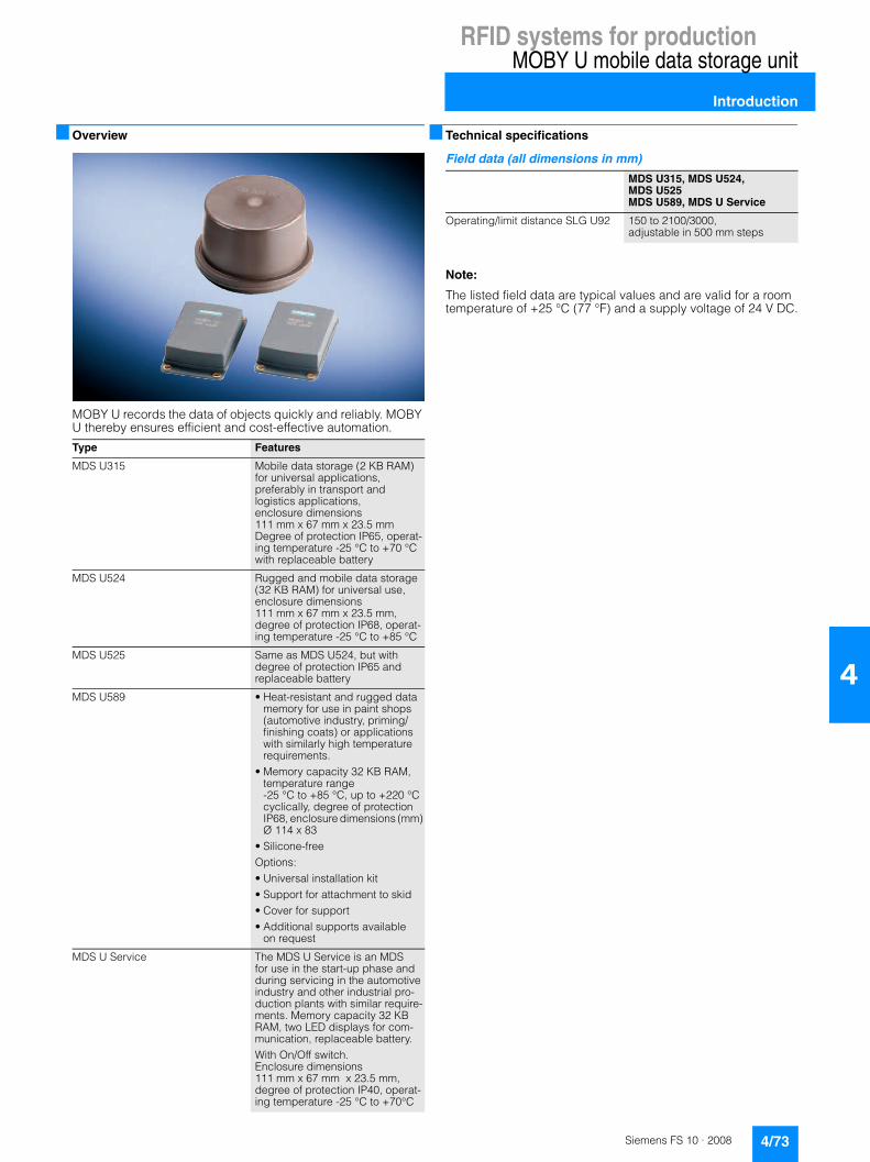
RFID systems for productionMOBY U mobile data storage unit
Introduction
4/73Siemens FS 10 · 2008
4
■ Overview
MOBY U records the data of objects quickly and reliably. MOBY U thereby ensures efficient and cost-effective automation.
■ Technical specifications
Field data (all dimensions in mm)
Note:
The listed field data are typical values and are valid for a room temperature of +25 °C (77 °F) and a supply voltage of 24 V DC.
Type Features
MDS U315 Mobile data storage (2 KB RAM) for universal applications, preferably in transport and logistics applications,enclosure dimensions111 mm x 67 mm x 23.5 mmDegree of protection IP65, operat-ing temperature -25 °C to +70 °Cwith replaceable battery
MDS U524 Rugged and mobile data storage (32 KB RAM) for universal use, enclosure dimensions 111 mm x 67 mm x 23.5 mm, degree of protection IP68, operat-ing temperature -25 °C to +85 °C
MDS U525 Same as MDS U524, but with degree of protection IP65 and replaceable battery
MDS U589 • Heat-resistant and rugged data memory for use in paint shops (automotive industry, priming/finishing coats) or applications with similarly high temperature requirements.
• Memory capacity 32 KB RAM, temperature range -25 °C to +85 °C, up to +220 °C cyclically, degree of protection IP68, enclosure dimensions (mm) Ø 114 x 83
• Silicone-free Options: • Universal installation kit• Support for attachment to skid• Cover for support• Additional supports available
on request
MDS U Service The MDS U Service is an MDS for use in the start-up phase and during servicing in the automotive industry and other industrial pro-duction plants with similar require-ments. Memory capacity 32 KB RAM, two LED displays for com-munication, replaceable battery. With On/Off switch. Enclosure dimensions 111 mm x 67 mm x 23.5 mm, degree of protection IP40, operat-ing temperature -25 °C to +70°C
MDS U315, MDS U524, MDS U525MDS U589, MDS U Service
Operating/limit distance SLG U92 150 to 2100/3000, adjustable in 500 mm steps

RFID systems for productionMOBY U mobile data storage unit
MDS U315/MDS U524/MDS U525
4/74 Siemens FS 10 · 2008
4
■ Overview
MDS U315
Mobile data storage unit (2 KB RAM) for universal applications, preferably in transport and logistics applications, enclosure dimensions 111 mm x 67 mm x 23.5 mm, degree of protection IP65, operating temperature -25 °C to +70 °C, with replaceable battery
MDS U524
Rugged and mobile data storage unit (32 KB RAM) for universal use, enclosure dimensions 111 mm x 67 mm x 23.5 mm, de-gree of protection IP68, operating temperature -25 °C to +85 °C
MDS U525
Same as MDS U524, but with degree of protection IP65 and replaceable battery
■ Technical specifications
1) The service life depends on the temperature, the time in which the MDS is located within the antenna field of the SLG (Zone 1 and 2) and the volume of data that is read/written.
Mobile data storage unit MDS U315 MDS U524 MDS U525
Memory size
• Fixed code memory 32-bit serial number
• Read-only memory 128 bit, to be written once by user
• Application memory 2 KB RAM 32 KB RAM
MTBF (at +40 °C) 2 400 000 h (without taking battery into account)
Write/read cycles unlimited / 109 at +25 °C
Write/read distance 150 mm to 3,000 mm
Bulk and multitag capability yes
Power supply Replaceable battery Battery Replaceable battery
Battery lifetime ≥5 years 1) ≥ 8 years 1)
Shock/vibration-resistant to DIN EN 60721-3-7, Class 7M3
50 g/10 g
Free fall height to DIN EN 60068-2-32 1 m
Torsion and bending load Not permissible
Suggested attachment 4 x M4 screws
Recommended distance to metal Can be directly mounted on metal
Degree of protection to EN 60529 IP65 IP68 IP65
Resistance to chemicals See configuration manual
Enclosure
• Dimensions (L x W x H) 111 mm x 67 mm x 23.5 mm
• Color/material Anthracite / plastic PA 12 GF 25
Ambient temperature
• During operation -25 °C to +70 °C -25 °C ... +85 °C
• During transportation and storage -40 °C to +85 °C
Weight, approx. 100 g
Special features Universal mobile data memory for the preferred deployment in transport and logistics
Rugged and mobile data memory for universal use

RFID systems for productionMOBY U mobile data storage unit
MDS U315/MDS U524/MDS U525
4/75Siemens FS 10 · 2008
4
Field data (all dimensions in mm)
MDS U315/MDS U524/MDS U525 to SLG U92
Ranges (Sg) of the SLG can be limited in 500 mm steps up to 3500 mm
The field data apply to write and read operations of the MDS.
■ Selection and Ordering data
A: Subject to export regulations AL = N and ECCN = EAR99H
■ Dimensions
Minimum Standard Maximum
Limit distance (Sg), approx.: 500 2000 3000
Operating distance (Sa) 350 1400 2100
Transmission window at Sa length / width 700700 (with FCC approval)
24002000 (with FCC approval)
30002100 (with FCC approval)
Order No.
Mobile data memoryMDS U315
A 6GT2 500-3BF10
2 KB RAM
Mobile data memory MDS U524
A 6GT2 500-5CE10
32 KB RAM
Mobile data memory MDS U525
A 6GT2 500-5CF10
32 KB RAM
���
���
����
��� �-�%"�-����%"�-����%"�-� ��%"�-� �
.����
��� ���
�������������

RFID systems for productionMOBY U mobile data storage unit
MDS U589
4/76 Siemens FS 10 · 2008
4
■ Overview
Heat-proof, rugged data storage unit for use in paintshops (automotive industry, primer/top coat) or applications with similar temperature requirements, memory capacity 32 KB RAM, tem-perature range -25 °C to + 85 °C, up to +220 °C cyclically, IP68 degree of protection, enclosure dimensions (mm) Ø 114 x 83
■ Technical specifications
1) The service life depends on the temperature, the length of time the MDS is located within the antenna field of the write/read device (Zones 1 and 2) and the volume of data that is read/written.
2) Applies only in connection with original bracket.
Field data (all dimensions in mm)
MDS U589 to SLG U92
Ranges (Sg) of the write/read device can be limited in 500 mm steps up to 3000 mm
Mobile data storage unit MDS U589 (heat-resistant)
Memory size
• Fixed code memory 32-bit serial number
• Read-only memory 128 bits, to be written once by user
• Application memory 32 KB RAM
MTBF (at +40 °C) 2,400,000 h (not taking the battery into account)
Read/write cycles Unlimited/ 109 at +25 °C
Read/write distance 150 mm to 3000 mm
Multitag capability Yes
Power supply Battery
Battery life ≥5 years 1)
Shock/vibration-resistant to DIN EN 60721-3-7, Class 7 M3
50 g / 5 g 2)
Free fall height to DIN EN 60068-2-32
1000 mm
Torsion and bending load not permissible
Suggested attachment See universal installation kit or skid support
Recommended distance from metal Can be directly mounted onto metal
Degree of protection per EN 60529 IP68
Chemical stability See Configuration Manual
Casing
• Dimensions (ø x H) 114 mm x 83 mm
• Color/material Brown/PPS
Ambient temperature
• During operation -25 °C to +85 °C, up to +220 °C cyclic
• During transportation and storage -40 °C to +85 °C
Weight, approx. 600 g
Special features Designed for integrated use in body-in-white and paintshops (KTL, top coat, ...)
Minimum Standard Maximum
Limit distance (Sg), approx.: 500 2000 3000
Operating distance (Sa) 350 1400 2100
Transmission window at Sa length / width 700700 (with FCC approval)
24002000 (with FCC approval)
30002100 (with FCC approval)

RFID systems for productionMOBY U mobile data storage unit
MDS U589
4/77Siemens FS 10 · 2008
4
Cyclic operation of the MDS at temperatures > 85 °C
At temperatures up to +85 °C, cyclic operation is not necessary, i.e. up to this temperature, the MDS can be in constant operation
■ Selection and Ordering data
A: Subject to export regulations AL = N and ECCN = EAR99H
■ Dimensions
Data carrier MDS U 589
Skid support
Universal holder with heat-proof data carrier MDS U589
Universal support
Heating up Cooling down
Temperature Time Temperature Time
220 °C Momentary 25 °C > 30 min
200 °C 1 h 25 °C > 4 h
200 °C 0,5 h 25 °C > 1 h
180 °C 1 h 25 °C > 3 h
Order No.
Mobile data memory MDS U589 6GT2 500-5JK10
32 KB RAM, up to 220 °C cyclic
Accessories
Skid-support for MDS U589
Short version A 6GT2 090-0QA00
Covering hood A 6GT2 090-0QB00
For skip support
Universal support 6GT2 590-0QA00
For MDS U589, e.g. for attachment to the body with a customer-specific adapter
�
��
��)��
��)��
)��
��)��
"!#�#$"
���)��*�
�+,��(����
&������'(��������������
,
����
''"($%@
�!"����'�&" 2��65
E &�� �!� ��%8���,�;�?�A���9
���
���
�����
��;�
� ���
� �
� � �
�
�
���
� �
�
��
�
� �
�
�
���������������
� � � � � � � �
� � � �
����
���
���
���� �
� � �

RFID systems for productionMOBY U mobile data storage unit
MDS U Service
4/78 Siemens FS 10 · 2008
4
■ Overview
MDS U Service
The MDS U Service is an MDS for use in the start-up phase and during servicing in the automotive industry and other industrial production plants with similar requirements.
Memory capacity 32 KB RAM, two LED displays for communica-tion, replaceable battery. With On/Off switch. Enclosure dimen-sions 111 mm x 67 mm x 23.5 mm, degree of protection IP40, operating temperature -25 °C to +70 °C
■ Technical specifications
1) After "voltage off" the information in the read-only memory is lost and must/can be written again.
2) The service life depends on the temperature. The MDS must not be located within the antenna range of the SLG (Zones 1 and 2).
3) The service life depends on the temperature, the length of time the MDS is located within the antenna field of the write/read device (Zones 1 and 2) and the volume of data that is read/written.
Mobile data storage unit MDS U Service
Memory size
• Fixed code memory 32-bit serial number
• Read-only memory 128 bit, to be written once by user1)
• Application memory 32 KB RAM
Read/write cycles Unlimited/ 109 at +25 °C
Read/write distance 150 mm to 3000 mm
Bulk and multitag capability Yes
Power supply Replaceable battery
Battery life
• MDS switched on, no communication and MDS outside antenna range approx. 1 year2)
• MDS switched on, with communication < 1 year3)
• MDS switched off ≥ 10 years
On/Off switch Voltage on/off
Indicators 2 LEDs
• Orange flashing Voltage On
• Green Communication
Torsion and bending load Not permissible
Suggested attachment 4 x M4 screws
Recommended distance from metal Can be directly mounted onto metal
Degree of protection as per EN 60529 IP40
Resistance to chemicals See Configuration Manual
Housing
• Dimensions (L x W x H) 111 mm x 67 mm x 23.5 mm
• Color/material Anthracite / plastic PA 12 GF 25
Ambient temperature
• During operation -25 °C to +70 °C
• During transportation and storage -40 °C to +85 °C
Weight, approx. 120 g
Special features MDS service for assignments during the start-up phase and for servicing. For implementation in the automotive industry and other industrial production plants with similar requirements.

RFID systems for productionMOBY U mobile data storage unit
MDS U Service
4/79Siemens FS 10 · 2008
4
Field data (all dimensions in mm)
MDS U service for SLG U92
Ranges (Sg) of the write/read device can be limited in 500 mm steps up to 3500 mm
The field data apply to write and read operations of the MDS.
■ Selection and Ordering data
■ Dimensions
Minimum Standard Maximum
Limit distance (Sg), approx.: 500 2000 3000
Operating distance (Sa) 350 1400 2100
Transmission window at Sa length / width 700700 (with FCC approval)
24002000(with FCC approval)
30002100 (with FCC approval)
Order No.
Mobile data storage MDS U Service
6GT2 500-5BF20
32 KB RAM
���
���
����
��� �-�%"�-����%"�-����%"�-� ��%"�-� �
.����
��� ���
�������������

RFID systems for productionMOBY U write/read device units
SLG U92
4/80 Siemens FS 10 · 2008
4
■ Overview
The compact and low-cost SLG U92 is a universal write/read device (SLG) with an integral antenna for applications where write/read distances of up to 3000 mm are required. Thanks to the automatic SLG synchronization via cable, it is possible to install up to three SLGs in a very small space.
Two different interfaces are available for the connection to a wide variety of systems:• RS 232; serial interface for connection to any system
(PC/PLC)• RS422; serial interface to the PC/PLC or to the MOBY interface
modules (SIMATIC RF170C, SIMATIC RF180C, ASM 475, ASM 456) for integration into SIMATIC S7, PROFIBUS, or Industrial Ethernet
Software tools such as the SIMATIC S7 functions (FB/FC45 / FC46 / FC55 / FC56) and the C library MOBY API for applications under Windows 98/NT/2000/XP allow for easy implementation in the respective application.
The integrated file management system (compatible with the familiar MOBY I file handler and supplemented with multitag-handling commands) ensures simple and user-friendly manage-ment of data on the mobile data memory.
For use in the USA and Canada, a version with radio approval FCC Part 15C is available.
■ Function
The SLG U92 operates with a transmission frequency in the ISM band between 2.4 and 2.4835 GHz. This supports transmission ranges from a few centimeters up to three meters for an ex-tremely low transmit power of < 10 mW EIRP and high net trans-mission rates up to 8 KB/s. Thanks to the selected transmission frequency, rugged modulation technique and appropriate check mechanisms, sources of electromagnetic interference can be disregarded and fault-free data transmission and data integrity are assured. MOBY U technology blocks the types of fault sources familiar in UHF transmissions such as reflections, interference and overrange. Matching antennas provide a homogeneous transmission field and ensure a detection rate of 100% for mobile data memories (MDS). There is no need for time-consuming shielding measures and antenna alignment.
The antenna field of the SLG can be activated and deactivated with a function call or triggered automatically by a sensor (BERO) for the duration of communication with an MDS.
For management of the data on the mobile data storage unit, there are two possibilities, as follows: • Byte-oriented addressing via absolute addresses
(start address, length)• Conveniently in a file management system
(compatible with the MOBY I file handler)
In file handler mode, the MOBY U write/read device always fetches the necessary file management information directly from the MDS and it can be operated in three steps:
1. For existing system solutions with MOBY I, MOBY U can be operated with the default settings and unmodified file handler functions without the MOVE and LOAD commands that are no longer required.
2. The default settings and requests for diagnostic data can be easily changed with just a few additional commands.
3. Utilization of all features including multitag processing. In this step, the commands and/or useful data can be uniquely assigned as well as the relevant MDS number.
Two LEDs indicate the current status (e.g. MDS in the field) and make start-up easier.
For easy start-up and diagnostics during normal operation, a separate service and diagnostics interface (RS232) is available. This interface can also be used by the service function "Load software in the SLG" to integrate future function expansions into existing applications without the need to replace the SLG.
The system interface (RS232 or RS422) can be used for serial connection to any other system (PC/PLC).
Type Features
SLG U92 Compact and low-cost write/read device with integral antenna for universal applications, write/read distances of up to 3000 mm (adjustable by software in 500 mm steps to 3500 mm) incl. file han-dler, degree of protection IP65, enclosure dimensions (mm) 290 x 135 x 42
SLG U92 with RS232 As above, but with RS232 inter-face for connection to PC/PLC
SLG U92 with RS422 As above, but with RS422 inter-face for connection to ASM (e.g. ASM 456, SIMATIC RF170C, ASM 475) or PC/PLC

RFID systems for productionMOBY U write/read device units
SLG U92
4/81Siemens FS 10 · 2008
4
■ Technical specifications
■ Selection and Ordering data
Write/read device SLG U92
Air interface to the MDS Integrated antenna
Transmission frequency 2.4 to 2.4835 GHz in the ISM band
Bandwidth 2 x 1 MHz within 83 MHz
Check mechanisms Forward-correction by means of systematic block code (CRC), ARQ procedure
Error rate < 1 reading error per 106 transactions
Data rate (write/read) (net) approx. 8 / 4.8 KB/s without bulkapprox. 4 / 2.4 KB/s for bulk size 2
Range (write/read) 150 mm to 3000 mm, see MDS field data
Local resolution Range can be limited in steps of between 500 mm and 3500 mm
Radiant power / intensity
• for SLG U92 versionwithout FCC approval
< 10 mW EIRP / <0.5 μW/cm2 (at a distance of 1 m)
• for SLG U92 versionwith FCC approval
< 50 mV/m at a distance of 3 m
Beam angle approx. 70° horizontal/vertical
Polarization Circular
Multi-identification capability up to 12 MDS
MDS recording time > 2 s for 12 MDS
Object speed (MDS) < 2 m/s if Sa = 1.5 m and read-ing/writing ≤ 2.5 KB data
SLG-SLG synchronization by means of semaphore control via second interface; max. 3 SLGs with one another
Minimum distance between two SLGs
> 6 m; if synchronized directlyside by side
Serial interface to ASM or PC
RS232 or RS422(SLG U92 variant),6-pin SLG connector according to EN 175201-804
Data transmission rate Automatic baud rate recognition 19.2 to 115.2 kbit/s (depending on cable length)
Transmission protocol 3964 R
Cable length, SLG - ASM/PC max. 1000 m (RS 422, shielded)
Cable length, SLG - PC max. 30 m / 300 m(RS 422, shielded)
Software functions
Commands MOBY file handler: Format data memory, create/delete file, write data to file, define access rights, etc. Direct reading/writing: read / write data, etc.
Programming FC45/FC46/FC55/FC56, see ASMC library for PC with Windows 98/NT/2000/XP
Service interface RS 232, 11-pin connectorto DIN EN 175201-804
Data transmission rate 19.2 kbit/s
Cable length SLG – PC (shielded) max. 20 m
Transmission protocol Terminal, ASCII characters
2 DI for BERO Triggering antenna field on/off
Cable length SLG – BERO (shielded)
max. 50 m
Interface for SLG-SLG synchroniza-tion (shielded)
max. cable length 30 m
Display elements 2 LEDs (data memory in field, errors, etc. )
MTBF (at +40 °C) 0.4 x 10⁶ hours
Power supply 24 V DC (rated value), 20 V DC to 30 V DC
Power consumption (transmitting) < 300 mA
Enclosure
• Dimensions (Lx W x H) in mm 290 x 135 x 42 (without connector)
• Color/material anthracite / plastic PA 12
• Mounting 4 x M6 screws
Shock/vibration-resistant to DIN EN 60721-3-7, Class 7 M3
30 g / 1.5 g
Degree of protection to EN 60529 IP65
Ambient temperature
• Operation -25 °C to +70 °C
• Transport and storage -40 °C to +85 °C
Weight, approx. 900 g
Special features • Active suppression of overreach• Automatic frequency hopping• Service functions for fast error
analysis • MOBY I - call-compatible (FC)
Order No.
SLG U92 with RS 422
Integral antenna 6GT2 501-0CA00
Integral antenna, FCC approval 6GT2 501-0BA00
SLG U92 with RS 232
Integral antenna 6GT2 501-1CA00
Integral antenna, FCC approval 6GT2 501-1BA00
Accessories
CD "RFID Systems Software & Documentation"
6GT2 080-2AA10
FB/FC for SIMATIC, 3964R driver for DOS/WINDOWS 95/NT/2000/XP, C-libraries, PC presentation program RFID documentation

RFID systems for productionMOBY U write/read device units
SLG U92
4/82 Siemens FS 10 · 2008
4
■ Dimensions
��
������
��
��� �-"/��-�
�
�
�
0"�� 1
��2(��"/��3+��3�+4�33+4(����+#$���� �������5+4&"�67�0"�� �+4�0"� �
���2(��3+��3�+4�33+4(����+
�#$���� �������5+4'48(3�(��45�3�
�4+����9
��������������
.�*�5+4���
�*
�*�

RFID systems for productionMOBY U write/read device units
STG U mobile handheld terminal
4/83Siemens FS 10 · 2008
4
■ Overview
The STG U is a powerful mobile handheld terminal with integral write/read antenna for applications in the field of production, logistics and service. In addition, it is an indispensable tool for commissioning and testing.
■ Design
The STG U mobile handheld terminal comprises a basic unit (based on the PSION Workaboutmx) and an antenna of the MOBY U type. It has a splash-proof housing (IP54), LCD display with 240 × 100 pixels, alphanumeric keypad and various inter-faces (for EEPROM card, charging the battery, RS232/TTL for the MOBY U antenna, battery charger interface incl. RS232 for connecting to the PC, etc.).
■ Function
The supplied MOBY software (memory card) provides service and test functions for reading, writing, etc. of the MOBY U data memory:• Reading data from the data memory• Writing data to the data memory• Reading and displaying the ID number of the data memory• Reading MDS status• Reading data from OTP memory• Writing data to OTP memory• Displaying and editing the data in hexadecimal, ASCII,
decimal and binary formats• Activating/deactivating password protection
On the basis of the optional C library, custom applications in-cluding a customized mask interface for the reading/writing of data memories can be very easily programmed. Various optional development tools for the PC and a wide selection of accesso-ries are available directly from PSION. This solution opens up new applications in the field of logistics and distribution. The handheld terminal for example allows for the offline recording and processing of commissioning data, which can then be for-warded to a PC/computer with a defined time delay.
■ Selection and Ordering data
A: Subject to export regulations AL = N and ECCN = EAR99HD: Subject to export regulations AL = N and ECCN = 4A994
■ Accessories
For optional components visit http://www.psionteklogix.com• "3link" connecting cable to the PC for easy exchange of data
between the PC and PSION Workaboutmx
• PSION Workaboutmx basic unit with large-area function keys and number pad
• Additional memory card with up to 8 MB memory• Docking station including rapid charger and software
for convenient exchange of data between the PSION Workaboutmx and the PC.
Technical specifications: See next page.
Order No.
STG U mobile handheld terminal
D 6GT2 503-0AA00
MOBY U handheld terminal STG U, complete (PSION Work-aboutmx), antenna STG U, battery, EEPROM card. With MOBY software, operating instructions, without power pack for STG U
Accessories
STG U antenna 6GT2 503-1AA00
For basic unit (PSION Workabout mx)
STG U power supply unit 6GT2 503-1DA00
Wide-range power supply unit 90 … 264 V AC, with cable switch, for the antenna STG U and the mobile handheld terminal STG U, with charging adapter
STG software A 6GT2 303-1CA00
For MOBY D, E, F, I and U, incl. operating instructions, 1 MB EEPROM card
CD: "RFID Systems Software & Documentation"
6GT2 080-2AA10
FB/FC for SIMATIC, 3964R driver for DOS/Windows 95/NT/2000/XP, C libraries, PC presentation program. MOBY documentation

RFID systems for productionMOBY U write/read device units
STG U mobile handheld terminal
4/84 Siemens FS 10 · 2008
4
■ Technical specifications
RAM/ROM 2 MB/2 MB
User program 1 MB (with MOBY service and test program)
Screen Graphic LCD screen with 240 × 100 pixels; gray scale; selectable backlighting
Keyboard Alphanumeric with 57 keys
Sound Piezo signal transmitter
Power supply NiCd battery pack with 2 type AA cells (850 mAh);fast-charging; automatic shutdownOperating time: approx. 20 hours (antenna inactive, display unlit)
Dimensions 282 mm x 235 mm x 93 mm (incl. MOBY U antenna)
Weight Approx. 1450 g(incl. MOBY U antenna)
Operating/storage temperature –20 °C … +60 °C/–25 °C … +70 °C (without battery)
Relative humidity 0 … 90 %, no condensation
Degree of protection IP54 (splash proof);for STG U only as complete unit
Impact resistance Max. drop onto concrete: 0.5 m
EMC EN 55022
Electrostatic; RF; EFT IEC 801-2; IEC 801-3; IEC 801-4
MOBY U antenna Air interface to the MDS
Transmission frequency 2.4 to 2.4835 GHz in the ISM band
Bandwidth 2 x 1 MHz within 83 MHz
Gross bit rate of the radio channel 384 Kbit/s
Data rate (write/read) (net) Approx. 8 / 4.8 KB/s without bulk
Antenna
• Direction of radiation Perpendicular to the rear panel of the MOBY U antenna
• Aperture angle Approx. 70 ° (conical antenna field)
• Polarization Circular
• Radiant power < 50 mV/m at a distance of 3 m
• Radiation density < 0.5 μW/cm2 at a distance of 1 m
Range (write/read) 150 … 3,000 mm
Local resolution Adjustable in steps of 0.5 m by means of range limitation
MDS recording time Approx. 3 s for 1 MDS(after actuation of the communica-tion key)
Power supply Lithium-ion battery pack 2SIP CGR18650 HG7.2 V 1.8 AhFast charging, automatic cutout,Service life approx. 500 charging cycles
Power consumption (antenna on) < 800 mA
Operating timeThe operating time corresponds to the ON time of the antenna; this means for every MDS function the time between pressing the commu-nication key and closing or termi-nating the selected MDS function.
> 2 months (antenna inactive)2 hours (antenna active)The antenna is switched on by means of the communication key only for communication and auto-matically switched off after the function has been performed.
Operating modes
• off Antenna switched off
• Search Ready to receive and evaluate search information sent by the MDS
• Communication Communication with the MDS: Write, read or initialize
Minimum distance to an SLG U92 or another STG U
> (set range + 0.5 m)
Serial interface (to basic unit) RS 232/115.2 Kbaud/3964R
Interface for battery charging 4-pin socket for connecting the STG U power supply unit
• Voltage / current 12 V DC / 1.225 A
• Charging period > 1.5 h (Lion battery pack 2SIP CGR18650 HG)
Control element Communication key(for triggering the communication)
Display elements LEDs
• LED for loading the batteries
- Lights up Power supply unit connected• Red: device is defective• Yellow: batteries are being
charged• Green: batteries are fully charged
- Does not light up Power supply unit is not connected
• LEDs for communication
- Lights up Communication key pressed and communication not complete• Red: battery capacity insufficient
for communication• Yellow: antenna is switched to ac-
tive
- Does not light up Communication terminated or not yet started
Enclosure
• Color Black
• Material VALOX® 357X
Approvals RF: EN 300 440-2SAR: EN 50 371Safety: EN 60 950-1EMC:• EN 301 489-01• EN 301 489-03• ENV 50 204FCC Part 15CUL/CSANot critical with regard to heart pacemakers
Programming Standard user interface for read-ing/writing of data memories, etc.
MOBY U antenna Air interface to the MDS

RFID systems for productionMOBY U write/read device units
Configuring instructions
4/85Siemens FS 10 · 2008
4
■ Overview
Note
Detailed information (clearance from metal, SLG-to-SLG clear-ance etc.) can be found in the "MOBY U Manual for Configura-tion, Assembly and Service“.
Field characteristics (battery-saving mode)
In contrast to the inductive RFID systems, UHF systems exhibit transmission behavior like electromagnetic waves. The wave length is approx. 13 cm. Metal surfaces reflect the waves and cannot be penetrated.
Despite a low radiation output, UHF systems have a relatively long range. The emission field has a directional characteristic which depends, however, on the antenna design. In order to keep the energy requirement low for the MDS and to make the determination of the location comprehensible, MOBY U has various function areas that are dependent on direction and distance. The three different zones of the transmission field are identified by different states and reactions of the components affected.
Cyclic operation of the MDS U589 at temperatures > 85 °C
At temperatures up to +85 °C, cyclic operation is not necessary, i.e. up to this temperature, the MDS can be in constant operation
Put simply, Zone 3 is an SLG-field-free area. The MDS "sleeps" and only listens momentarily every 0.5 s for a sign of life from an SLG. This means that the power consumption is very low. If other UHF users in the vicinity are occupying the same frequency band, it has no effect on the MDS, as the latter requires a special code to wake it up. If the MDS in the vicinity of an active SLG then receives this special code, it enters Zone 2 (see Fig.).It immediately accepts the SLG and responds briefly with its own identification. The SLG however ignores every MDS unless it is in Zone 1, whose radius parameter can be set in stages in the SLG. The power consumption in Zone 2 is not significantly higher than in Zone 3.
If the MDS enters Zone 1, it is duly registered by the SLG and the data exchange can begin. Now all read and write functions can be performed. However, as the transmission rate at the air inter-face is very high (80 Kbit/s), the overall communication time is very short. For example, all bytes of the 32 KB memory are read in about 8 seconds. This means that the data exchange imposes hardly any load on the battery.

RFID systems for productionMOBY U write/read device units
Configuring instructions
4/86 Siemens FS 10 · 2008
4
SLG U92 with integral antenna
Example: car body identification
Example: skid identification
�%"�-� �
"/��-�
���� �� ���������� ��
��������������
�%"�-� �
"/��-�
+4 +4
��������������
������
������

RFID systems for logisticsIntroduction
4/87Siemens FS 10 · 2008
4
RFID systems for logistics – Identifying potential for optimizationRFID systems have been setting new standards in control and management tasks in distribution and logistics for a number of years, especially in terms of reliability with applications ranging from the identification of containers and recognition of textiles in dispatch centers and even in frozen storage. The rewritable, low-cost data memories as well as SmartLabels can be reliably identified and read, even through dirt.
Systems are based on the ISO 15693 standard as well as EPCglobal and ISO/IEC 18000-6, so SmartLabels from different manufacturers can be used. With the "electronic delivery note", you always have all the information at hand. Simple as well as complex tasks are performed quickly and reliably. Whatever the requirements, the optimal system is available. Additional equip-ment such as a mobile handheld terminal provide additional flex-ibility in operation.
Application• Dispatch warehouse including order picking ("brown goods",
foodstuffs, tires, etc.).• Cold-storage depots (including order picking)• Container or vessel identification • Identification of load carriers, pallets, cases or mini-load con-
tainers• Distribution and loading control with electronic delivery note• Parts identification for textiles (e.g. professional rental cloth-
ing, operating room textiles) in laundries• Identification of window parts, items of furniture etc. in the lo-
gistics chain• Parts identification in the clothing industry (e.g. shirts, suits,
medical stockings) • Production and shipping• Goods distribution in open distribution chains, e.g. in parcel
and postal services, mail order companies or freight forward-ers
• Luggage transport and tracking• Machine and plant construction• Industrial production• Laboratory and test equipment
Highlights• Manage your procedures with rewritable
electronic data storage units/SmartLabels • Wide range of data storage units • Mobile and flexible with handheld terminals• Customized SmartLabel/Antenna for high-volume
applications
Logistics
MOBY D SIMATIC RF600
Write/read distance Up to 0.9 m Up to 5.0 m (two antennas side by side)
Up to 10.0 m (antennas in gate arrangement)
Frequency 13.56 MHz 865 - 868 MHz (Europe)902 - 928 MHz (North America)
Standards ISO 15693ISO 18000-3
EPCglobalISO 18000-6B, ISO 18000-6C

RFID systems for logisticsIntroduction
4/88 Siemens FS 10 · 2008
4
■ Technical specifications
1) Further tags and SmartLabels will be available soon2) This feature will be available in the future
MOBY D SIMATIC RF600
Write/read distance Up to 680 mm (900 mm with customer-specific antenna) Up to 5 m (up to 10 m for gate arrangement)
Data transmission rate ≥ 3.5 ms/byte reading, ≥ 9.5 ms/byte writing Up to 320 KB/s reading, up to 128 KB/s writing
Memory EEPROM
Standards ISO 15693 EPC Gen 1, EPC Gen 2, ISO 18000-6B, ISO 18000-6C
Approvals EN 300330 (Europe), FCC, IC ETSI EN 302208, FCC
Bulk capability • (PC version with RS 232) •Multitag capability • (PC version with RS 232) •Frequency 13.56 MHz adjustable: 865 - 868 MHz (Europe),
902 - 928 MHz (USA)
Mobile data memo-ries (tags/labels)
Name Memory size
Operating temperature
Degree of pro-tection
Designation1)
Memory size
Operating temperature
Degree of protec-tion
MDS D160MDS D100MDS D124MDS D139MDS D324Smart Label(customer-specific version for high quantities)
112 bytes112 bytes112 bytes44 bytes
992 bytes112/256 bytes
-25 ... +175 °C-25 ... +80 °C-25 ... +125 °C-25 ... +200 °C-25 ... +125 °C-25 ... +85 °C
IP68IP68IP67IP68IP67IP68
RF620LRF630L
RF640T
EPC 96 bitEPC 96 bit
216 bytes
-20 ... +70 °C-40 ... +85 °C(+80 °C cycl.)
-25 ... +85 °C
Accord-ing to version, none or IP65
IP68
Write/read devices Name Operating temperature
Degree of protection Name Operating temperature
Degree of protection
Stationary, with detached antenna
SLG D10SLG D10SSLG D11 ANT D5SLG D11S ANT D5
-20 ... +55°C-20 ... +55°C-25 ... +70°C-25 ... +70°C
IP65IP65IP65IP65
RF660R -25 ... +55 °C IP65
Stationary, with integrated antenna
SLG D12SLG D12S
-25 ... +70°C-25 ... +70°C
IP65IP65
Mobile handheld terminal with inte-grated antenna
STG D -20 ... +50 °C IP54
Antennas Name Operating temperature
Degree of protection Name Operating temperature
Degree of protection
ANT D5ANT D6ANT D10
-20 ... +55 °C-20 ... +55 °C-20 ... +55 °C
IP65IP65IP65
RF660A -25 ... +75 °C IP67
Connection to the automation system
directly via communication module (ASM)
directly via communications module (ASM) 2)
SIMATIC S7-300, S7-400
• •
PROFIBUS DP 1111• •PROFINET •Ethernet (TCP/IP) 1111 •Serial interface to other controllers, PCs, any other systems
• •
Page 4/89 4/114

RFID systems for logisticsMOBY D
Introduction
4/89Siemens FS 10 · 2008
4
■ Overview
MOBY D is a new RF identification system based on the Standard 15693 in the 13.56 MHz range. For the first time, the standard creates a common basis for SmartLabels from different manufacturers (e.g. I-Code, Tag-it).
Due to the reasonable prices of the SmartLabels in large volume applications and the simple system integration, MOBY D is the ideal identification system for the above applications.
Depending on the write/read distance, various write/read devices are available with integral or separate antennas.
The MOBY D identification system boasts the following features:• 13.56 MHz identification system for SmartLabels/data storage
based on I-Code 1 or ISO/IEC 15693 (I-Code SLI, Tag-it HFI) with a write/read clearance of up to 900 mm (MDS-/SLG-de-pendent)
• Special heat-resistant data storage (44-byte EEPROM) for paintshops up to +200 °C
• Very high level of reliability even in the presence of contamina-tion, temperature fluctuations and electromagnetic interfer-ence
• Can be connected via serial interface to any system, e.g. PC with Windows 9x/NT
• Simple integration into SIMATIC and the PROFIBUS DP
■ Benefits
Worldwide support, configuration and service support.
■ Application
Main applications of MOBY D:
Applications extend from simple identification, such as elec-tronic barcode substitution, supplementation, or delivery note in harsh environments, storage and distribution logistics, right up to product identification.
The design of the transponder permits a variety of flexible designs, guaranteeing optimum dimensioning for the widest variety of applications.
Low-cost SmartLabels for large volume applications: • Container and box identification in open systems• Distribution logistics and goods identification• Parcel and mail services, mail order businesses and freight
carriers• Baggage check-in and baggage tracking• Protection against plagiarism and theft
Advantages of SmartLabels over conventional barcode labels • Rugged and reliably recognizable, even when contaminated
(moisture, dust, etc.)• Maintenance-free and resistant to aging• Identification even of packages made of non-metallic
materials• Rewritable (unlimited read cycles, write cycles typically
1 000 000)
As many as 20 SmartLabels per second can be detected simultaneously (serial numbers in the case of bulk recognition). The data can be processed selectively in multitag mode.
Hardened data stores (closed systems) • Container and box identification in logistics and distribution• Production logistics and in assembly lines with higher tem-
perature requirements (e.g. paintshops, temperature range up to +200 °C)
• Parts identification (e.g. data storage is attached directly to product/pallet).
■ Function
MOBY identification systems ensure that important data accom-panies a product from the very start.Due to their extremely attractive price, SmartLabels can be uni-versally implemented as "an electronic barcode substitute" or as a "delivery note".
Using stationary as well as mobile write/read devices (SLGs), the necessary information (production data, transport routes, etc.) can be read without contact (inductively), and even be supplemented or modified without the need for a direct line-of-sight link.

RFID systems for logisticsMOBY D
Introduction
4/90 Siemens FS 10 · 2008
4
■ Technical specifications
1) On request
Type Contactless RF identification system
Transmission frequency data/energy
13.56 MHz
Memory capacity Dependent on chip used:• I-Code 1: 44-byte
user memory • I-Code SLI: 112-byte
user memory (ISO 15693)8 byte fixed code as serial number
Memory type EEPROM
Write/read cycles > 1 000 000/unlimited
Data management 4 byte, block by block
Data transmission rate MDS - SLG Approx. 3.5 ms/byte (reading); approx. 9.5 ms/byte (writing)
Write/read distance Up to 680 mm (900 mm with customer-specific antenna1))
Operating temperature (MDS) -25 to +80 °C, +125 °C, +175 °C, +200 °C
Degree of protection Up to IP68
Can be connected to PC with Windows 98/NT, PLC SIMATIC S7, PROFIBUS DP
Special features • For SmartLabels/data storage based on I-Code 1 or ISO/IEC 15693, e.g. I-Code SLI, Tag-it HFI
• CRC checksums for secure data transmission
• Bulk recognition and multitag function
Approvals CE, EN 300330, FCC, IC

RFID systems for logisticsMOBY D mobile storage unit
Introduction
4/91Siemens FS 10 · 2008
4
■ Overview
Customer-specific data memory
Customer-specific data memory (packaging, temperature range, geometry etc.) on request.
■ Design
The MOBY D data storage/SmartLabel mainly comprises logic with an integrated EEPROM memory and an antenna.
■ Function
If an MDS moves into the transmission field of the SLG, the nec-essary power for all circuit components is generated and moni-tored by means of the energy supply unit. The pulse-coded in-formation is prepared in such a way that it can be processed further as pure digital signals. The handling of data, including check routines, is performed by the control unit (SLG) which also manages the user memory.
Type Features
MDS D... Customer-specific SmartLabel (e.g. 112-byte EEPROM),e.g. in credit card format:• Degree of protection
up to IP68• Temperature range
up to +80 °C• Typ. dimensions in mm:
55 x 55, 86 x 54• Max. read/write distance
up to 900 mm (large customer-specific antenna/SmartLabel)
MDS D100 Universal data memory (112-byte EEPROM) in credit card format:• Degree of protection IP68 • Temperature range up to +80 °C• Max. read/write distance:
650 mm
MDS D124 Rugged data memory for deploy-ment in harsh industrial environ-ments and under extreme environmental conditions:• Degree of protection IP67 • Temperature range
up to +125 °C• Max. read/write distance:
180 mm
MDS D139 Re-usable data memory for use in paintshops of applications with high temperatures (44-byte EEPROM, (Ø 85 mm x 15 mm)):• Degree of protection IP68 • Temperature range
up to +200 °C• Max. read/write distance:
550 mm
MDS D160 The EEPROM data memory (Ø 16 mm x 3 mm) has been specially designed for harsh environments in the laundry and cleaning industry.• Main applications include:
- Rented work clothing - Rented laundry- OP textiles, hospital clothing- Hotel laundry- Dirt collection mats
• 112 byte EEPROM • Degree of protection IP68 • Temperature range
up to +175 °C• Max. read/write distance
160 mm
MDS D324 Rugged data memory for deployment in harsh industrial environments and under extreme environmental conditions:• Degree of protection IP67 • Temperature range
up to +125 °C• Max. read/write distance:
180 mm
Type Features

RFID systems for logisticsMOBY D mobile storage unit
Introduction
4/92 Siemens FS 10 · 2008
4
■ Technical specifications
Field data (operating/limit distance) of MDS and SLG(all dimensions in mm)
The field data (unaffected by metal) for all MOBY D components of the MDS and SLG are shown in the table below. Thus it becomes particularly easy to select the right MDS and SLG. The listed technical data are typical values and are valid for a room temperature of +25 °C and a supply voltage of 24 V DC.
Type MDS D... customer-specific, e.g. with SmartLabel 86 x 54
MDS D100 MDS D124 MDS D139 MDS D160 MDS D324
SLG D12/D12S 0 ... 150 0 ... 120 / 160 0 ... 50 / 70 0 ... 120 / 150 0 ... 45 / 65 0 ... 60 / 80
SLG D11/D11S ANT D5 0 ... 300 0 ... 300 / 380 0 ... 70 / 110 0 ... 240 / 300 0 ... 65 / 90 0 ... 100 / 150
SLG D10/D10S ANT D5 0 ... 500 0 ... 400 / 480 0 ... 130 / 180 0 ... 380 / 450 0 ... 120 / 160 0 ... 160 / 220
SLG D10/D10S ANT D6 0 ... 650 0 ... 550 / 650 0 ... 130 /180 0 ... 480 / 550 0 ... 120 / 160 0 ... 160 / 220
SLG D10/D10S ANT D10 0 ... 500 0 ... 400 / 480 0 ... 130 /180 0 ... 380 / 450 0 ... 120 / 160 0 ... 160 / 220

RFID systems for logisticsMOBY D mobile storage unit
MDS D100
4/93Siemens FS 10 · 2008
4
■ Overview
This mobile data storage unit is a passive, maintenance-free transponder based on ISO 15693 with I-Code SLI technology.
■ Application
Applications extend from simple identification, such as elec-tronic bar code substitution or supplementation, over storage and distribution logistics, to product identification.
This mobile data storage unit can also be used without any diffi-culty under harsh environmental conditions (e.g. at a tempera-ture up to +80 °C).
■ Technical specifications
■ Selection and Ordering data
A: Subject to export regulations AL = N and ECCN = EAR99H
■ Dimensions
Mobile data storage unit MDS D100
Memory size 112 byte EEPROM available 8-byte serial number (read-only code)
Protocol to ISO 15693
MTBF at +40 °C 2000000 h
Read cycles Unlimited
Write cycles, min. 100000
Write cycles, typical 1000000
Data retention time 10 years (at < +40 °C)
Read/write distance, max. 650 mm (see field data)
Memory organization 4 byte, block by block
Multitag capability Yes, depending on SLG
Energy source Inductive power transmission (without battery)
Vibration ISO 10 373/ISO 7810
Torsion and bending load ISO 10 373/ISO 7816-1
Mounting Fixing lug/adhesive
Recommended spacing from metal 25 mm (approx. 30 % reduction of the field data)
Degree of protection to EN 60529 IP68
Enclosure Laminated plastic card,printable on both sides
• Dimensions (L x W x H) in mm 85.6 x 54 x 0.9
• Color/material White/petrol / PC
Ambient temperature
• Operation -25 °C to +80 °C
• Transport and storage -25 °C to +80 °C
Weight, approx. 5 g
Field data in mm - without metallic influence
MDS D100 to: SLG D12/D12S SLG D11/D11S ANT D5
SLG D10/D10S ANT D5
SLG D10/D10S ANT D6
SLG D10/D10S ANT D10
Operating distance (Sa) 0 ... 120 0 ... 300 0 ... 400 0 ... 550 0 ... 400
Limit distance (Sg) 160 380 480 650 480
Transmission window (L) 120 Ø 300 Ø 320 520 1050
Minimum distance from MDS to MDS ≥ 500 ≥ 1000 ≥ 1000 ≥ 1500 ≥ 200
Order No.
Mobile data storage unit MDS D100
A 6GT2 600-0AD10
112 byte EEPROM, IP68, max. + 80 °C
Accessories
Fixing lug 6GT2 190 0AB00
for MDS D100
Spacer 6GT2 190-0AA00
For fixing lug, thickness 20 mm The purpose of the spacer is to maintain the recommended dis-tance to the metal when installing the tag.
���� ��� �
� ���
���� ���
��������������

RFID systems for logisticsMOBY D mobile storage unit
MDS D124
4/94 Siemens FS 10 · 2008
4
■ Overview
The MDS D124 is a passive, maintenance-free transponder based on ISO 15693 with I-Code SLI technology.
■ Application
This mobile data storage can also be used without any difficulty under harsh environmental conditions (e.g. at a temperature up to +125 °C).
■ Technical specifications
■ Selection and Ordering data
■ Dimensions
Mobile data storage unit MDS D124
Memory size 112 byte EEPROM available 8-byte serial number
Protocol to ISO 15693
MTBF 1500000 hours
Read cycles Unlimited
Write cycles, at +70 °C min. 100000
at ≤ 40 °C, typical 1000000
Data retention time > 10 years (at < +40 °C)
Read/write distance, max. 180 mm (see field data)
Memory organization Block by block access
Multitag capability Yes, depending on SLG
Energy source Inductive power transmission (without battery)
Shock/vibration-resistant to EN 60721-3-7, Class 7 M3
See configuration manual
Torsion and bending load Not permissible continuously
Mounting Adhesive, screws
Recommended spacing from metal > 25 mm
Degree of protection to EN 60529 IP67
Resistance to chemicals See configuration manual
Enclosure
• Dimensions Ø 27 mm x 4 mm
• Color/material Black/epoxy resin
Ambient temperature
• Operation -25 °C to +125 °C
• Transport and storage -40 °C to + 150 °C
Weight, approx. 5 g
Field data in mm - without metallic influence
MDS D124 to: SLG D12/D12S SLG D11/D11S ANT D5
SLG D10/D10S ANT D5
SLG D10/D10S ANT D6
SLG D10/D10S ANT D10
Operating distance (Sa) 0 ... 50 0 ... 70 0 ... 130 0 ... 130 0 ... 130
Limit distance (Sg) 70 110 180 180 180
Transmission window (L) 120 Ø 300 Ø 320 440 980
Minimum distance from MDS to MDS ≥ 300 ≥ 800 ≥ 800 ≥ 1200 ≥ 1800
Order No.
Mobile data storage unit MDS D124
6GT2 600-0AC00
112 byte EEPROM, IP67, max. + 150 °C
�
�������������
� ��
��
�
��

RFID systems for logisticsMOBY D mobile storage unit
MDS D139
4/95Siemens FS 10 · 2008
4
■ Overview
The MDS D139 is a passive, maintenance-free transponder based on the I-Code 1 technology.
■ Application
Low-cost, heat-resistant transponder for use in production logis-tics and assembly lines with high temperatures (max. +200 °C, e.g. in paintshops).
■ Technical specifications
1) Reduction of the operating/limit distance by about 20 % above 100 °C. At 200 °C processing is not possible.
■ Selection and Ordering data
■ Dimensions
Mobile data storage unit MDS D139
Memory size 44 byte EEPROM available 8-byte serial number
Protocol I-Code 1
MTBF 2000000 h
Read cycles Unlimited
Write cycles
• at +70 °C min. 10000
• at ≤ 40 °C, typical 500000
Data retention time > 10 years (at < +40 °C)
Read/write distance, max. 550 mm (see field data)
Memory organization Block by block access
Multitag capability Yes, depending on SLG
Energy source Inductive power transmission (without battery)
Shock/vibration-resistant toEN 60721-3-7,Class 7 M3
50 g/20 g
Torsion and bending load Not permissible
Mounting M5 screw
Recommended spacing from metal > 30 mm
Degree of protection to EN 60529 IP68
Ex approval ATEX Zone 2G
Resistance to chemicals See configuration manual
Enclosure
• Dimensions Ø 85 mm x 15 mm
• Color/material Black/plastic PPS
Ambient temperature
• Operation - °C to +140 °C 1)
- tested up to 4000 h continuous temperature, 1500 temperature cycles
+ 200 °C max.
- temporarily + 220 °C
• Transport and storage -40 ... +100 °C
Weight, approx. 50 g
Special features No silicone
Field data in mm – without metallic influence
MDS D139 to: SLG D12/D12S SLG D11/D11S ANT D5
SLG D10/D10S ANT D5
SLG D10/D10S ANT D6
SLG D10/D10S ANT D10
Operating distance (Sa)1) 0 ... 120 0 ... 240 0 ... 380 0 ... 480 0 ... 380
Limit distance (Sg)1) 150 300 450 550 450
Transmission window (L) 120 Ø 300 Ø 320 520 1050
Minimum distance from MDS to MDS ≥ 500 ≥ 1000 ≥ 1000 ≥ 1500 ≥ 2000
Order No.
Mobile data storage unit MDS D139
6GT2 600-0AA00
44 byte EEPROM, IP68, max. + 200 °C
Accessories
Spacer 6GT2 690-0AA00
�� ��
���
���
�%������
�

RFID systems for logisticsMOBY D mobile storage unit
MDS D160
4/96 Siemens FS 10 · 2008
4
■ Overview
■ Application
Typical applications include:• Rented work clothing• Hotel laundry• Surgical textiles• Hospital clothing• Dirt collection mats• Clothing for nursing homes/hostels
■ Technical specifications
1) Reduction of the operating/limit distance by about 20 % above 100 °C. At 140 °C processing is not possible.
■ Selection and Ordering data
A: Subject to export regulations AL = N and ECCN = EAR99H
■ Dimensions
Mobile data storage unit MDS D160
Memory size 112 byte EEPROM available 8-byte serial number
Protocol to ISO 15693
MTBF 2,500,000 h
Read cycles Unlimited
Write cycles, at +70°C min. 10000
at ≤ 40 °C, typical 1000000
Data retention time > 10 years (at < +40 °C)
Read/write distance, max. 160 mm (see field data)
Memory organization Block by block access
Multitag capability Yes, depending on SLG
Energy source Inductive power transmission (without battery)
Shock/vibration-resistant to EN 60721-3-7, Class 7 M3
See configuration manual
Torsion and bending load Not permissible continuously
Mounting Patch, sew, glue
Recommended spacing from metal > 25 mm
Degree of protection to EN 60529 IP68 (2 m, 24 hours)
Resistance to chemicals All chemicals normally usedin the washing process
Enclosure
• Dimensions Ø 16 mm x 3 mm ± 0.1 mm
• Color/material Black/epoxy resin
Ambient temperature
• Operation -25 to +85 °C Up to +120 °C 1) for 1000 hUp to +160 °C 1) for 35 hUp to +175 °C for 10 minutes
• Transport and storage -40 °C to + 85 °C
Weight, approx. 1.2 g
Special features at least 100 wash cycles24 hour regeneration time required between wash cycles
Field data in mm – without metallic influence
MDS D160 to: SLG D12/D12S SLG D11/D11S ANT D5
SLG D10/D10S ANT D5
SLG D10/D10S ANT D6
SLG D10/D10S ANT D10
Operating distance (Sa) 1) 0 ... 45 0 ... 65 0 ... 120 0 ... 120 0 ... 100
Limit distance (Sg) 1) 65 90 160 160 160
Transmission window (L) 120 280 Ø 300 480 980
Minimum distance from MDS to MDS ≥ 300 ≥ 800 ≥ 800 ≥ 1200 ≥ 1800
Order No.
Mobile data storage unit MDS D160
A 6GT2 600-0AB10
112 byte EEPROM, IP68, max. +175 °C, momentary
���������������������������
� � ����!�"�
��

RFID systems for logisticsMOBY D mobile storage unit
MDS D324
4/97Siemens FS 10 · 2008
4
■ Overview
The MDS D324 is a passive, maintenance-free transponder based on the ISO standard 15693 with my-d technology. It was developed for the application areas in production and distribu-tion logistics as well as product identification.
For the user, the usable application memory amounts to 992 byte.
This mobile data memory can also be easily used in harsh environments under extreme environmental conditions (e.g. with higher temperature load).
■ Technical specifications
Field data in mm (excluding metal influence)
■ Selection and Ordering data
Mobile data storage unit MDS D324
Memory size 992 byte EEPROM available8 byte serial number
Protocol According to ISO 15693
MTBF 1500000 h
Read cycles unlimited
Write cycles, at +70 °C, min. 10000
at ≤ 40 °C, typical 1000000
Data retention time > 10 years (at < +40 °C)
Read/write distance, max. 220 mm (see field data)
Memory organization Block-by-block access
Multitag capability Yes, depending on SLG
Energy source Inductive energy transfer(without battery)
Shock/vibration to EN 60721-3-7, Class 7 M3
See configuration manual
Torsion and bending load No continuous load permissible
Mounting glue, screw
Recommended distance to metal > 25 mm
Degree of protection to EN 60529 IP67
Resistance to chemicals See configuration manual
Enclosure
• Dimensions Ø 27 mm x 4 mm
• Color/material Black/epoxy resin
Ambient temperature
• During operation -25 ... +125 °C
• During transportation and storage -40 ... + 150 °C
Weight, approx. 5 g
MDS D324 to: SLG D12/D12S SLG D11/D11S ANT D5
SLG D10/D10S ANT D5
SLG D10/D10S ANT D6
SLG D10/D10S ANT D10
Operating distance (Sa) 0 ... 60 0 ... 100 0 ... 160 0 ... 160 0 ... 160
Limit distance (Sg) 80 150 220 220 220
Length of transfer window(L or Lx/Ly)
120/60 Ø 300 Ø 320 500/400 1000/280
Width of transfer window(B or Bx/By)
48/24 120 128 200/160 400/112
Minimum distance from MDS to MDS
≥ 300 ≥ 800 ≥ 800 ≥ 1200 ≥ 1800
Order No.
Mobile data memory MDS D324
A 6GT2 600-3AC00
Button, 992 byte EEPROM user memory, max. +125 ° C

RFID systems for logisticsMOBY D mobile storage unit
SmartLabel
4/98 Siemens FS 10 · 2008
4
■ Overview
■ Application
Thanks to their very reasonable price, the SmartLabels can be used universally as electronic "barcode substitutes” or “delivery notes".
■ Design
The design of the customer-specific SmartLabels permits a variety of flexible designs, ensuring optimum dimensioning for the widest variety of applications.
■ Technical specifications
■ Selection and Ordering data
Mobile data storage unit MDS D... (customized design)
Memory size (for I-code), e.g. 112 or 256 byte EEPROM available 8-byte serial number
Protocol to ISO 15693
Read cycles Unlimited
Write cycles at ≤ 40 °C, typical > 1000000
Data retention time > 10 years (at < +40 °C)
Read/write distance, max. 900 mm (see field data)
Memory organization Block by block access
Multitag capability Yes, depending on SLG
Energy source Inductive power transmission
Mounting E.g. single-sided adhesive attachment
Recommended spacing from metal > 10 mm
Degree of protection to EN 60529 Up to IP68
Resistance to chemicals On request
Enclosure
• Dimensions in mm e.g. 86 x 54 or 55 x 55
• Color/material E.g. upper side plastic Lower side double-sided transfer adhesive on silicon Paper
Ambient temperature
• Operation E.g. -25 °C to +85 °C
• Storage temperature +20 to +30 °C
Weight, approx. E.g. 3 g
Special features • Temperature range, size, degree of protection, mounting, operating distance etc. all depend on the customer-spe-cific design of the SmartLabels
• High-volume applications• On request
Order No.
SmartLabel On request
112 to 256 byte EEPROM, custom-specific version for high-volume applications

RFID systems for logisticsMOBY D write/read devices
Introduction
4/99Siemens FS 10 · 2008
4
■ Overview
The write/read device (SLG) ensures inductive communication and power supply to the MDS and for the serial connection (RS232 or RS422) to various systems (PC, PLC).
Write/read devices in the upper, medium and lower performance ranges are available to users for integration into SIMATIC S7 and PROFIBUS DP V1. The MOBY communication modules are used for connecting the write/read devices to SIMATIC and PROFIBUS DP V1.
Various different SLGs are available for small, medium and large distances to the MDS to satisfy customer requirements.
A rugged housing or antenna enclosure and a high degree of protection allow the use under tough environmental conditions and guarantees a high resistance to many chemical substances. New applications are opened up by the support of SmartLabels on the basis of the ISO/IEC 15693 standard, multitag capability, etc.
Type Features
SLG D10 ANT D5 Universal write/read device with detached antenna (340 mm x 325 mm x 38 mm)• Max. read/write distance: 480 mm• Degree of protection IP65• Temperature range up to +55 °C• With RS 232 interface
for connection to PC/PLC
SLG D10S ANT D5 Like SLG D10 ANT D5, but with RS422 interface for connection to SIMATIC S7/ PROFIBUS via ASM 452, ASM 456, ASM 473 or ASM 475
SLG D11 ANT D5 Universal write/read devicewith detached antenna (340 mm x 325 mm x 38 mm)• Max. read/write distance: 380 mm• Degree of protection IP65• Temperature range up to +55 °C• With RS 232 interface
for connection to PC/PLC
SLG D11S ANT D5 Like SLG D11 ANT D5, but with RS422 interface for connection to SIMATIC S7/ PROFIBUS via ASM 452, ASM 456, ASM 473 or ASM 475
SLG D12 Universal write/read device with integral antenna (160 mm x 80 mm x 40 mm)• Max. read/write distance: 160 mm• Degree of protection IP65• Temperature range up to +55 °C• With RS 232 interface
for connection to PC/PLC
SLG D12S Like SLG D12, but with RS422 interface for connection to SIMATIC S7/ PROFIBUS via ASM 452, ASM 456, ASM 473 or ASM 475
SLG D10 basic unit Write/read device with plugfor connection of an external antenna (ANT D5 / ANT D6 / ANT D10)• Degree of protection IP65• Temperature range up to +55 °C• RS 232 interface for connection
to PC/PLC
SLG D10S basic unit Write/read device with plug for connection of an external antenna (ANT D5 / ANT D6 / ANT D10)• Degree of protection IP65• Temperature range up to 55 °C• RS422 interface for connection to
SIMATIC S7/ PROFIBUS via ASM 452, ASM 456, ASM 473 or ASM 475
ANT D5 Universal antenna (340 mm x 325 mm x 38 mm), connectable to basic units SLG D10/SLG D10S• Degree of protection IP65• Temperature range up to 55 °C• Cable length 3.6 m (permanently
connected on antenna side)
ANT D6 Universal antenna(580 mm x 480 mm x 110 mm), connectable to basic units SLG D10/SLG D10S• Degree of protection IP65• Temperature range up to 55 °C• Cable length 3.3 m (connectable at both
ends, included in scope of delivery)
ANT D10 Antenna (1150 mm x 365 mm x 115 mm) for storage, logistics and distribution.Ideally suited to the clothing industry/laundries. For connection to SLG D10and D10S. Advantageous geometry for small tags and a long transmission field.Main areas of application: Container identification, goods identifi-cation, package and postal services, dispatch, haulage, clothing industry, laundries• Degree of protection IP65• Temperature range up to 55 °C• Cable length 3.3 m
(connectable at both ends, included in scope of delivery)
• Cover included in scope of supply
Type Features

RFID systems for logisticsMOBY D write/read devices
Introduction
4/100 Siemens FS 10 · 2008
4
■ Design
The following serial interfaces including software tools (on the CD "RFID Systems Software & Documentation") are available for quick and easy integration into the application:• RS232 with binary protocol
- For serial interfacing to any system (PC/PLC)- C++ library MDWAPI (for Windows 9x/2000/NT) with ex-
tended range of functions including password protection, access authorization and multitag operation
• RS422 with 3964R protocol - For serial interface to the MOBY communication modules
(ASM 450, ASM 452, AM 473, ASM 475) or any system, e.g. gateways
- FC45 (without multitag, etc.) for SIMATIC S7-300/400, S7 PROFIBUS Master
■ Function
The SLG converts the commands (read MDS etc.) received by the PC or interface module (ASM) and generates by means of the antenna a magnetic alternating field for the contactless com-munication and power transmission to the MDS.
Failsafe protocols and access mechanisms achieve a high de-gree of data security and guarantee fast, secure and noise-resis-tant communication. The transmittable volume of data between SLG/antenna and MDS depends on:• the speed at which the MDS moves through the transmission
window of the antenna• the length of the transmission window
■ Technical specifications
Field data in mm
Minimum distance from SLG to SLG
SLG D12/SLG D12S SLG D12/SLG D12S > 600 mm
SLG D11 ANT D5/SLG D11S ANT D5 SLG D11 ANT D5/SLG D11S ANT D5 > 1200 mm
SLG D10 ANT D5/SLG D10S ANT D5 SLG D10 ANT D5/ SLG D10S ANT D5 > 2000 mm
SLG D10 ANT D6/SLG D10S ANT D6 SLG D10 ANT D6/ SLG D10S ANT D6 > 2000 mm
SLG D10 ANT D10/SLG D10S ANT D10 SLG D10 ANT D10/SLG D10S ANT D10 > 2000 mm

RFID systems for logisticsMOBY D write/read devices
SLG D10/SLG D10S basic unitwith ANT D5 and ANT D6 and ANT D10 antenna
4/101Siemens FS 10 · 2008
4
■ Overview
The SLG D10 / SLG D10S basic units are write/read devices in the upper performance range and can be operated with the ANT D5, ANT D6 and ANT D10 antennas.
The write/read devices are equipped with an RS232 serial inter-face for connection to PCs/PLCs or RS422 interface which per-mits communication via the communications modules ASM 456, RF170C, RF180C, ASM 475 to SIMATIC S7 or PROFIBUS/PROFINET.
Connectable switch and antennas:
Antenna switch
The antenna switch enables several individual antennas or portal solutions to be operated with only one write/read device (SLG D10 / SLG D10S).
ANT D5
An antenna for universal applications designed for warehouse, logistics and distribution applications. The high degree of protection (IP65) enables the antenna to be used under harsh industrial conditions.
ANT D6
An antenna in the upper performance range, designed for warehouse, logistics and distribution applications. It can be used wherever high speeds are required together with a large write/read distance.
ANT D10
The ANT D10 is suitable for use in warehouses, logistics and distribution. An antenna with this geometry is required in the clothing industry and laundries in particular.
■ Technical specifications
Basic units SLG D10 SLG D10S
Inductive interface to the MDS Remote antenna
Transmission frequency (energy/data) 13.56 MHz; ISO/IEC 15693
Data memories / transponders supported For SmartLabels based on standard ISO/IEC 15693 e.g.: I Code SLI, Tag-it HFI, plus I-Code 1
Multitag capability Yes, approx. 20 data memories/s No
Read/write distance, max. see MDS field data
Transmit power Up to 10 W
Serial interface RS232 to PC/SPS RS422 to ASM 475
Max. cable length at 24 V DC 30 m 300 m
Connector 9-pin subminiature connector (pin)
Data transmission rate 1200 baud to 115.2 Kbaud (adjustable) Up to 115.2 Kbaud (depending on ASM)
Procedure Binary with CRC 16-security 3964R protocol
Software functions
• Programming C library for PCs with Windows 9x/2000 and NT
FB/FC45 for S7
• Commands Read data from MDS, write data to MDS, access rights, multitag, etc.
Read data from MDS, write data to MDS
Rated supply voltage value/permissible range via 4-pin connector M12 (IP65) 24 V DC/20 V – 30 V DC
Power consumption (at room temperature)
• Inrush current, momentary Up to 2.8 A/50 ms
• Operation Typ. 0.9 A
Dimensions (in mm)for electronics without connector
320 x 145 x 100
Color/Material Anthracite/aluminum
Degree of protection to EN 60529 IP65
Shock-resistant acc. to EN 60721-3-7, Class 7M2 30 g
Vibration-resistant acc. to EN 60721-3-7, Class 7M2 1 g (9 Hz to 200 Hz); 1,5 g (200 Hz to 500 Hz)
Attachment of enclosure 4 x M6 screws
Ambient temperature
• During operation - 20 to + 55 °C
• During transportation and storage - 25 to + 70 °C
MTBF 75000 h
Weight 3.5 kg

RFID systems for logisticsMOBY D write/read devicesSLG D10/SLG D10S basic unitwith ANT D5 and ANT D6 and ANT D10 antenna
4/102 Siemens FS 10 · 2008
4
Antenna ANT D5 ANT D6 ANT D10
Inductive interface to the MDS 13.56 MHz
Read/write distance, max. See field data
Interface to SLG D10 / SLG D10S
• Plug connection TNC
• Antenna cable length(included in scope of delivery)
3.6 m (plugs into SLG) 3.3 m (connectable on both sides)
Antenna dimensions in mm 340 x 325 x 38 (without range adjustment kit)
580 x 480 x 110 (without cover) 1150 x 365 x 115 (with cover)
Antenna color Black Black/gray Pastel turquoise
Antenna material Plastic ASA Aluminum/plastic
Degree of protection to EN 60529 IP65
Shock-resistant acc. to EN 60721-3-7, Class 7M2
30 g
Vibration-resistant acc. to EN 60721-3-7, Class 7M2
1 g (9 Hz to 200 Hz); 1.5 g (200 Hz to 500 Hz)
Attachment of the antenna 4 x M5 screws 4 x M6 screws
Ambient temperature
• During operation -20 to +55 °C
• During transportation and storage -25 to +70 °C
MTBF 300000 h
Weight 1.0 kg 3.3 kg 10 kg
Antenna duplexer
Max. input power 10 W
Transmission frequency 13.56 MHz
Power supply Not required
Connector (inputs and outputs) TNC
Dimensions (L x W x H) in mm 160 x 80 x 40 without connector
• Color Anthracite
• Material Plastic PA 12
• Mounting 2 x M5 screws
Vibration-resistant to EN 60721-3-7, Class 7 M2 1 g (9 to 200 Hz)1.5 g (200 to 500 Hz)
Shock-resistant to EN 60721-3-7, Class 7 M2 30 g
Degree of protection to EN 60529 IP65
Resistance to chemicals On request
Ambient temperature
• During operation -25 to +65 °C
• During transportation and storage -25 to +75 °C
MTBF 300000 h
Weight, approx. 400 g
Approval CE

RFID systems for logisticsMOBY D write/read devices
SLG D10/SLG D10S basic unitwith ANT D5 and ANT D6 and ANT D10 antenna
4/103Siemens FS 10 · 2008
4
■ Selection and Ordering data
A: Subject to export regulations AL = N and ECCN = EAR99H
■ Dimensions
Basic unit (left), antenna ANT D5 (right)
Antenna ANT D6
Antenna ANT D10
Order No.
Write/read device SLG D10 A 6GT2 698-1AA00
Basic unit (without antenna) with RS 232 serial interface for connection to PC/PLC
Write/read device SLG D10S A 6GT2 698-2AA00
Basic unit (without antenna) with RS 422 serial interface for con-nection to SIMATIC S7/PROFIBUS via ASM 456 or ASM 475
Accessories
Antenna ANT D5 A 6GT2 698-5AA00
For SLG D10 / SLG D10S basic units
Range adjustment kit for ANT D5
A 6GT2 698-5AB00
Antenna ANT D6
For SLG D10 / SLG D10S basic units
6GT2 698-5AF00
Covering hood for ANT D6
Serves as protection against contact
6GT2 690-0AB00
Antenna ANT D10 6GT2 690-0AD00
For SLG D10 / SLG D10S basic units, cover and antenna cable included in scope of supply
Antenna switch
For connecting several antennas (ANT D5 or ANT D6) to one SLG D10 / SLG D10S, IP65,-25 °C to +65 °C
A 6GT2 690-0AC00
MOBY D cables
• Cable between ANT D6 and SLG D10/SLG D10S, antenna switch; length 3.3 m
A 6GT2 691-0CH33
• Cable extension between ANT D6 and SLG D10/SLG D10S, antenna switch; length 7.2 m
A 6GT2 691-0DH72
CD: "RFID Systems Software & Documentation"
6GT2 080-2AA10
FB/FC for SIMATIC, 3964R driver for DOS/Windows 95/NT/2000/XP, C libraries, PC presentation program. RFID documentation
���
���
���
���
���
���
(
���
�����
���
��������
�
��)��������������%��*
�$%���+������
,$�-��-��*".�'���
���/�0��"�1"����1$�������"����$--�%���1"����
�
��)�����'���
FS10_00239
50
6,5
M6
6,5
M650M6
M6
220
270
303
320370403580
480
110
50
890
FS10
_002
38
50
6,5
6,5
M O B Y D
940
973
1150
105155188365
M6
M6
115

RFID systems for logisticsMOBY D write/read devices
SLG D10 ANT D5/SLG D10S ANT D5
4/104 Siemens FS 10 · 2008
4
■ Overview
■ Technical specifications
Type SLG D10 ANT D5 SLG D10S ANT D5
Inductive interface to the MDS Remote antenna
Transmission frequency (energy/data) 13.56 MHz; ISO/IEC 15693
Data memories / transponders supported For SmartLabels based on standard ISO/IEC 15693 e.g.: I Code SLI, Tag-it HFI
Multitag capability Yes, approx. 20 data memories/s Available soon
Read/write distance, max. 1) 480 mm, see MDS field data
Antenna cable length (included in scope of delivery)
3.6 m
Transmit power Up to 4 W
Serial interface RS232 to PC/SPS RS422 to ASM 456, ASM 475, RF170C, RF180C
Max. cable length at 24 V DC 30 m 300 m
Connector 9-pin subminiature connector (pin)
Data transmission rate 1200 baud to 115.2 Kbaud (adjustable) Up to 115.2 Kbaud (depending on ASM)
Procedure Binary with CRC 16-security 3964R protocol
Software functions
• Programming C library for PCs with Windows 9x/2000 and NT FB/FC45 for S7
• Commands Read data from MDS, write data to MDS, access rights, multitag, etc.
Read data from MDS, write data to MDS
Rated supply voltage value/permissible range Via 4-pin device connector M12 (IP65) 24 V DC/20 V – 30 V DC
Power consumption (at room temperature)
• Inrush current, momentary Up to 2.8 A/50 ms
• Operation Typ. 0.9 A
Enclosure
• Dimensions in mm- For antenna 340 x 325 x 38- For electronics without connector 320 x 145 x 100
• Color of antenna/SLG enclosure Black/anthracite
• Material antenna/SLG enclosure Plastic ASA/aluminum
Degree of protection to EN 60529, enclosure/antenna (front)
IP65/IP65
Antenna connector (connectable to SLG) TNC connector
Shock resistant to EN 60721-3-7 30 g, Class 7M2
Vibration resistant to EN 60721-3-7 1 g (9 Hz to 200 Hz) 1.5 g (200 Hz to 500 Hz), Class 7M2
Attachment of enclosure 4 x M6 screws
Attachment of the antenna 4 x M5 screws

RFID systems for logisticsMOBY D write/read devices
SLG D10 ANT D5/SLG D10S ANT D5
4/105Siemens FS 10 · 2008
4
1) In order to guarantee optimum field data in metallic environments, the antenna is calibrated at the factory at a distance of 100 mm from metal (see clearance kit 6GT2 690-0AB00).
■ Selection and Ordering data
A: Subject to export regulations AL = N and ECCN = EAR99H
■ Dimensions
Ambient temperature
• During operation -20 to +55 °C
• Transport/storage -25 to +70 °C
MTBF
• Readers 75000 h
• Antenna 300000 h
Weight
• Basic unit 3.5 kg
• Antenna 1 kg
Type SLG D10 ANT D5 SLG D10S ANT D5
Order No.
Write/read device SLG D10 ANT D5
A 6GT2 601-0AA00
With RS 232 serial interface
Write/read device SLG D10S ANT D5
A 6GT2 602-0AA00
With RS 422 serial interface
Accessories
Range adjustment kitfor ANT D5
6GT2 690-0AB00
Antenna duplexer A 6GT2 690-0AC00
For connecting several antennas (ANT D5 or ANT D6)to one SLG D10 / SLG D10S, IP65, -25 °C to +65 °C
CD "RFID Systems Software & Documentation"
6GT2 080-2AA10
FB/FC for SIMATIC, 3964R driver for DOS/Windows 95/NT/2000/XP, C-libraries, PC presentation program, RFID documentation
���
���
���
���
���
���
(
���
�����
���
��������
�
��)��������������%��*
�$%���+������
,$�-��-��*".�'���
���/�0��"�1"����1$�������"����$--�%���1"����
�
��)�����'���

RFID systems for logisticsMOBY D write/read devices
SLG D11 ANT D5/SLG D11S ANT D5
4/106 Siemens FS 10 · 2008
4
■ Overview
■ Technical specifications
Type SLG D11 ANT D5 SLG D11S ANT D5
Inductive interface to the MDS Remote antenna
Transmission frequency (energy/data) 13.56 MHz; ISO/IEC 15693
Data memories / transponders supported For SmartLabels based on standard ISO/IEC 15693 e.g.:I Code SLI, Tag-it HFI, plus I-Code 1
Multitag capability Yes, approx. 20 data memories/s no
Read/write distance, max. 1) 380 mm, see MDS field data
Antenna cable length 3.6 m
Transmit power 1 W
Serial interface RS232 to PC/SPS RS422 to ASM 456, ASM 475, RF170C, RF180C
Max. cable length at 24 V DC 30 m 300 m
Connector 9-pin subminiature connector (pin)
Data transmission rate 1200 baud to 38.4 Kbaud (adjustable) Up to 38.4 Kbaud
Procedure/data backup Binary with CRC 16-security 3964R protocol
Software functions
• Programming C library for PCs with Windows 9x/2000 and NT
FB/FC45 for S7
• Commands Read data from MDS, write data to MDS, access rights, multitag, etc.
Read data from MDS, write data to MDS
Rated supply voltage value/permissible range
Via 4-pin device connector M12 (IP65) 24 V DC/20 V – 30 V DC
Power consumption (at room temperature)
• Inrush current, momentary Up to 600 mA/50 ms
• Operation Typ. 150 mA
Enclosure
• Dimensions in mm- For antenna 340 x 325 x 38- For the electronics 160 x 80 x 40 without connector
• Color of antenna/SLG enclosure Black/anthracite
• Material antenna/SLG enclosure Plastic ASA/plastic PA 12
Antenna connector (connectable to SLG) TNC connector
Degree of protection to EN 60529, enclosure/antenna (front)
IP65
Shock resistant to EN 60721-3-7, Class 7M2Total shock response spectrum, Type II
30 g
Vibration-resistant acc. to EN 60721-3-7, Class 7M2
1 g (9 to 200 Hz); 1.5 g (9 to 500 Hz)

RFID systems for logisticsMOBY D write/read devices
SLG D11 ANT D5/SLG D11S ANT D5
4/107Siemens FS 10 · 2008
4
1) In order to guarantee optimum field data in metallic environments,the antenna is calibrated at the factory at a distance of 100 mmfrom metal (see clearance kit 6GT2 690-0AB00).
■ Selection and Ordering data
A: Subject to export regulations AL = N and ECCN = EAR99H
■ Dimensions
Attachment of enclosure 2 x M5 screws
Attachment of the antenna 4 x M5 screws
Ambient temperature
• During operation -25 to +55 °C
• During transportation and storage -25 to +70 °C
MTBF
• Readers 200000 h
• Antenna 300000 h
Weight
• Basic unit Approx. 0.6 kg
• Antenna Approx. 1 kg
Type SLG D11 ANT D5 SLG D11S ANT D5
Order No.
Write/read device SLG D11 A 6GT2 601-0AC00
With separate antenna ANT D5With RS 232 serial interface
Write/read device SLG D11S A 6GT2 602-0AC00
With separate antenna ANT D5With RS 422 serial interface
Accessories
Range adjustment kit for ANT D5
6GT2 690-0AB00
CD "RFID Systems Software & Documentation"
6GT2 080-2AA10
FB/FC for SIMATIC, 3964R driver for DOS/Windows 95/NT/2000/XP, C libraries,PC presentation program MOBY documentation ���
2
���
���
��4����3����
���
���3� �
��
���
(
����
�� ��
�
���/�0��"�1"����1$�������"����$--�%���1"����
�����������%��*�$%���+������
,$�-��-��*".��3���
���4�(
5����"�
�������������,

RFID systems for logisticsMOBY D write/read devices
SLG D12/SLG D12S
4/108 Siemens FS 10 · 2008
4
■ Overview
■ Technical specifications
Type SLG D12 SLG D12S
Inductive interface to the MDS Integrated antenna
Transmission frequency (energy/data)
13.56 MHz; ISO/IEC 15693
Data memories / transponders supported For SmartLabels based on the ISO/IEC 15693 standard e.g. I-Code SLI, Tag-it HFI, additional I-Code 1
Multitag capability Yes, approx. 20 data memories/s Yes, available soon
Max. 160 mm, see MDS field data
Serial interface RS232 to PC/SPS RS422 to ASM 456, ASM 475, RF170C, RF180C
Max. cable length at 24 V DC 30 m 300 m
Connector 9-pin subminiature connector (pin)
Data transmission rate 1200 baud to 38.4 Kbaud (adjustable) Up to 38.4 Kbaud
Procedure Binary with CRC 16-security 3964R protocol
Software functions
• Programming C library for PCs with Windows 9x/2000 and NT FB/FC45 for S7
• Commands Read data from MDS, write data to MDS, access rights, multitag, etc.
Read data from MDS, write data to MDS
Rated supply voltage value/permissible range Via 4-pin device connector M12 (IP65) 24 V DC/20 V – 30 V DC
Power consumption (at room temperature)
• Inrush current, momentary Max. 600 mA
• Operation Typ. 150 mA
Enclosure
• Dimensions in mm 160 x 80 x 40
• Color Anthracite
• Material Plastic PA 12
• Attachment of enclosure 2 x M5 screws
Degree of protection to EN 60529 IP65
Shock-resistant acc. to EN 60721-3-7, Class 7M2
30 g
Vibration-resistant to EN 60721-3-7, Class 7M2
1.0 g (9 to 200 Hz); 1.5 g (200 to 500 Hz)
Ambient temperature
• During operation -25 to +55 °C
• During transportation and storage -25 to +70 °C
MTBF 200000 h
Weight, approx. 0.5 kg

RFID systems for logisticsMOBY D write/read devices
SLG D12/SLG D12S
4/109Siemens FS 10 · 2008
4
■ Selection and Ordering data
A: Subject to export regulations AL = N and ECCN = EAR99H
■ Dimensions
Order No.
Write/read device SLG D12 A 6GT2 601-0AB00
With RS 232 serial interface and integrated antenna
Write/read device SLG D12S A 6GT2 602-0AB00
With RS 422 serial interface and integrated antenna
Accessories
CD "RFID Systems Software & Documentation"
6GT2 080-2AA10
FB/FC for SIMATIC, 3964R driver for DOS/Windows 95/NT/2000/XP, C libraries, PC presentation program. RFID documentation
�2�
"��2
��2���
��
���4�(
6
7
��
����
( �
����
���
���
��
�'�

RFID systems for logisticsMOBY D write/read devices
STG D mobile handheld terminal
4/110 Siemens FS 10 · 2008
4
■ Overview
The STG D is a powerful mobile handheld terminal with integral write/read antenna for applications in the field of production logistics, distribution and service. In addition, it is an indispens-able tool for commissioning and testing.
■ Design
The STG D mobile handheld terminal consists of one basic unit (Basis PSION Workabout PRO) and a removable compact read/write head. It has a splash water-proof enclosure (IP54), LCD color monitor 1/4 VGA, 320 x 240 pixels, TFT portrait format, alphanumeric keyboard and various interfaces (for SD memory card, charging batteries, USB, Bluetooth, etc.).
■ Function
The pre-installed MOBY software provides service and test functions for reading, writing, etc. of the MOBY data memory:• Reading data from the data memory • Writing data to the data memory • Reading and displaying the ID number of the data memory
(to the extent available)• Displaying and editing the data in hexadecimal, ASCII,
decimal and binary formats • Activate/deactivate password
User applications that were developed for the predecessor model Workabout MX can be transferred to this terminal with little effort. For this purpose, various optional development tools for the PC are available directly from PSION. This is opening up new applications in the field of logistics and distribution, for example, the handheld terminal enables commissioning data to be recorded or processed offline and forwarded to the PC/computer with a time delay.
■ Technical specifications
STG D mobile handheld terminal
Processor 400 MHz Intel Xscale PXA255
Operating system Microsoft Windows CE .NET 4.20
RAM/Flash EEPROM memory 128 MB/32 MB
User program MOBY standard application
Screen TFT color touch display, ¼ VGA 320 x 240 (portrait format); adjustable backlighting
Keyboard alphanumeric
Sound Piezo signal transmitter
Power supply • Lithium-ion battery(3.7 V; 3000 mAh)
• Quick charging possible(automatic shut-off) or 3 x 1.5 V type AA
• Backup battery: 3 V ML 2032 lithium cell
Interfaces • LIF interface (low insertion force interface) for battery charging and communication with the PC using a docking and loading sta-tion (USB)
• CF interface for expansion cards (e.g. WLAN)
Dimensions 305 x 90 x 44 [mm]
Weight (incl. battery) Approx. 0.5 kg
Ambient temperature
• During operation -10 °C ...+50 °C
• Storage (without batteries) -25 °C ...+60 °C
Relative humidity, non-condensing 5 ... 90 %
Degree of protection IP54 (splash water proof)
EMC EN 55022, EN 55024
Integral read/write head, inductive interface to MDS
Read/write distance to MDS up to 80 mm, depending on MDS
Energy/data transmission frequency 13.56 MHz
Serial interface (to basic unit) TTL, 3964R protocol
Functionality of the SW application Standard user interfacefor reading/writingof data memories, etc.

RFID systems for logisticsMOBY D write/read devices
STG D mobile handheld terminal
4/111Siemens FS 10 · 2008
4
■ Selection and Ordering data
A: Subject to export regulations AL = N and ECCN = EAR99HD: Subject to export regulations AL = N and ECCN = 4A994
■ Accessories
For optional components, please visit http://www.psionteklogix.com
For example:• SD expansion cards• Handles, belt loops• Vehicle holder with charging function n
Order No.
STG D mobile handheld terminal with MOBY D read/write head
A 6GT2 603-0AA10
Basic unit (PSION Workabout PRO) with MOBY D read/write, battery, standard software pre-installed, without loading/docking station
Accessories
Loading/docking station A 6GT2 898-0BA00
For a mobile handheld terminalas well as a spare battery, incl. wide-range plug-in power supply 100 ... 240 V AC and country-specific adapters as well as USB cable
MOBY D read/write head A 6GT2 603-1AA10
For basic unit (PSION Workabout mx and PSION Workabout PRO)
Basic unit D 6GT2 003-0AA10
Basic unit (PSION Workabout PRO) with adapter for MOBY RFID read/write heads
Spare battery A 6GT2 898-0CA00
For basic unit (PSION Workabout PRO), High Capacity 3000 mAh, Li-ion
CD: "RFID Systems Software & Documentation"
6GT2 080-2AA10
FB/FC for SIMATIC, 3964R driver for DOS/Windows 95/NT/2000/XP, C libraries, PC presentation program. MOBY documentation

RFID systems for logisticsMOBY D
Configuring instructions
4/112 Siemens FS 10 · 2008
4
■ Overview
Note
Detailed configuration and commissioning data is contained in the “Manual for Configuration, Assembly and Service”.
Transmission window
The write/read device generates an inductive alternating field. The field is at its strongest near the antenna and declines con-siderably as the distance from the antenna increases. The distri-bution of the field depends on the structure and geometry of the antennas in the write/read device and MDS.
A prerequisite for the function of the MDS is a minimum field strength at the MDS that is achieved at a distance Sg from the write/read device. The picture below shows the transmission window between MDS and SLG:
Sa: Operating distance between MDS and SLG
Sg: Limit distance (maximum clear distance between upper sur-face of antenna and MDS, at which the transmission can still function under normal conditions)
L: Length of a transmission window
SP: Intersection of the axes of symmetry of the MDS
The transmittable quantity of information between SLG and MDS depends on:• the speed at which the MDS passes the antenna ("passing
speed")• Length of the inductive alternating field of the SLG, through
which the MDS moves ("transmission window").
Communication between SLG and MDS
The communication between SLG and MDS is asynchronous.
�%"
�%"
"�"�
/
&$��%�
/
"7
���������
�4��'�(''(+�
$+������
���������
:(�+:
���
�����
������
Data transmission rate SLG - MDS
Read ≥ 3.5 ms/byte
Write ≥ 9.5 ms/byte
Transmission time of ID number
• SLG D10 ANT 5, ANT D6, ANT D10
• SLG D10S ANT 5
30 ms (8 byte at 115.2 kbit/s)
• SLG D12S ANT 5, ANT D6, ANT D10
• SLG D11S ANT 5
90 ms (8 byte at 19.2 kbit/s)
• SLG D12 ANT D5, ANT D6, ANT D10
• SLG D11 ANT D5
60 ms (8 byte at 38.4 kbit/s)

RFID systems for logisticsMOBY D
Configuring instructions
4/113Siemens FS 10 · 2008
4
Speed at which SLG passes over(for a transponder in the field)
Type SLG D10 ANT D10 SLG D10 ANT D6 SLG D10 ANT D5 SLG D11 ANT D5 SLG D12
UID number (8 byte) ≤ 15 m/s ≤ 8.0 m/s ≤ 5.0 m/s ≤ 3.5 m/s ≤ 2.5 m/s
I-Code 1, e.g. MDS D139
Read (with 4 byte of user data) ≤ 10 m/s ≤ 6.5 m/s ≤ 3.5 m/s ≤ 3.0 m/s ≤ 2.0 m/s
Write (with 4 byte of user data) ≥ 7,5 m/s ≤ 5.0 m/s ≤ 2.8 m/s ≤ 2.5 m/s ≤ 1.5 m/s
Read (with 44 byte of complete user data)
≤ 6 m/s ≤ 3.8 m/s ≤ 2.0 m/s ≤ 1.8 m/s ≤ 1.0 m/s
Write (with 44 byte of complete user data)
≤ 2.5 m/s ≤ 1.4 m/s ≤ 0.8 m/s ≤ 0.6 m/s ≤ 0.3 m/s
I-Code SLI, e.g. MDS D100
Read (with 4 byte of user data) ≤ 10 m/s ≤ 6.0 m/s ≤ 3.5 m/s ≤ 1.6 m/s ≤ 1.4 m/s
Write (with 4 byte of user data) ≤ 9 m/s ≤ 5.5 m/s ≤ 3.0 m/s ≤ 1.2 m/s ≤ 1.2 m/s
Read (with 112 byte of complete user data)
≤ 7.5 m/s ≤ 4.0 m/s ≤ 2.4 m/s ≤ 1.4 m/s ≤ 1.0 m/s
Write (with 112 byte of complete user data)
≤ 2 m/s ≤ 1.0 m/s ≤ 0.6 m/s ≤ 0.4 m/s ≤ 0.2 m/s
Type SLG D10S ANT D10 SLG D10S ANT D6 SLG D10S ANT D5 SLG D11S ANT D5 SLG D12S
UID number (8 byte) ≤ 6.0 m/s ≤ 3.8 m/s ≤ 2.0 m/s ≤ 1.0 m/s ≤ 0.8 m/s
I-Code 1, e.g. MDS D139
Read (with 4 byte of user data) ≤ 5.5 m/s ≤ 3.5 m/s ≤ 1.8 m/s ≤ 1.0 m/s ≤ 0.8 m/s
Write (with 4 byte of user data) ≤ 4.5 m/s ≤ 2.5 m/s ≤ 1.4 m/s ≤ 0.8 m/s ≤ 0.6 m/s
Read (with 44 byte of complete user data)
≤ 4.5 m/s ≤ 2.8 m/s ≤ 1.5 m/s ≤ 0.7 m/s ≤ 0.6 m/s
Write (with 44 byte of complete user data)
≤ 2.2 m/s ≤ 1.2 m/s ≤ 0.7 m/s ≤ 0.5 m/s ≤ 0.3 m/s
I-Code SLI, e.g. MDS D100
Read (with 4 byte of user data) ≤ 6.5 m/s ≤ 4.0 m/s ≤ 2.2 m/s ≤ 3.0 m/s ≤ 1.2 m/s
Write (with 4 byte of user data) ≤ 5.5 m/s ≤ 3.4 m/s ≤ 1.8 m/s ≤ 2.8 m/s ≤ 1.0 m/s
Read (with 112 byte of complete user data)
≤ 5.0 m/s ≤ 3.0 m/s ≤ 1.6 m/s ≤ 2.2 m/s ≤ 0.8 m/s
Write (with 112 byte of complete user data)
≤ 2.0 m/s ≤ 1.0 m/s ≤ 0.6 m/s ≤ 0.5 m/s ≤ 0.2 m/s

RFID systems for logisticsSIMATIC RF600
Introduction
4/114 Siemens FS 10 · 2008
4
■ Overview
SIMATIC RF600 is a contact-free RFID system (RFID: Radio Frequency IDentification), that has been specially designed for applications in logistics and supply chain management.
SIMATIC RF600 operates in the UHF frequency band and is designed for identifying tags based on the EPCglobal standard. It is, therefore, the ideal system for storing and reading out infor-mation in EPC format (EPC: Electronic Product Code) on low-cost SmartLabels (single-use data carriers) and to transfer it to higher-level software systems for further processing.
■ Benefits
Due to the omission of manual counting, recording and subse-quent procedures, cost savings are achieved and recording errors are minimized.
By using low-cost, passive SmartLabels, goods can be auto-matically identified throughout the entire logistics chain. Wrong information at the goods transfer points is avoided and the consistency of data and information is secured.
The throughput of the supply chain can be increased by identi-fying several articles simultaneously which increases productiv-ity.
SIMATIC RF600 opens up opportunities for integration in down-stream software systems. The flow of goods and information can then be linked in "realtime". As soon as the data that is associ-ated with an item is read, e.g. when the item has passed through a loading gate, the information in the supply management chain can be automatically updated and then, for example, reordering can be triggered.
By tracking and tracing goods, transparency is increased throughout the system: The route of an item can be traced at any time.
■ Application
SIMATIC RF600 is primarily used for non-contact identification of containers or palettes and for detection of goods in bulk. These applications are usually open circulating routes in which passive SmartLabels are applied to goods, products, bundles or trans-port units. The system proves its worth in these applications with high read rates, high-speed data transmission and the ability to cope with long read distances.
The system is also suitable for reading and writing reusable data carriers (Industrial Tags), conventionally used in closed circulat-ing routes.
The main application areas therefore range from recognition of goods in loading and unloading bays, through goods flow control on conveyor systems as far as implementation in ware-houses or distribution centers and for fill level checks in high-bay stores. Industrial applications in factories, e.g. in paint shop con-veyors or assembly lines in the automotive industry, are just as common.
■ Design
Optional: Flexible installation of antenna with articulated bracket thanks to the Antenna Mounting Kit. The package includes a 75 mm x 75 mm Vesa adapter.

RFID systems for logisticsSIMATIC RF600
Introduction
4/115Siemens FS 10 · 2008
4
■ Function
SIMATIC RF identification systems ensure that important data accompanies the product from the very beginning.
Different tags are used to store product-specific data and infor-mation: Depending on the field of application, SmartLabels or Industrial Tags.
In the case of tags to the EPCglobal standard, information re-garding the manufacturer of the goods, the article class and the respective serial number is coded in 96 bit (EPC Gen1). Tags of the second generation of the EPCglobal standard (EPC Gen2) allow customer or product information to be stored additionally.
In the case of tags based on the ISO 18000-6B standard (reusable data carriers), data volumes up to 216 byte can be stored which can be freely defined by the user.
■ Technical specifications
1) This interface will only be available in the future
Type SIMATIC RF600
Conformity ETSI EN 302208, FCC
Area of application Europe, USA
Frequency range (adjustable) • 865 … 868 MHz (Europe)• 902 … 928 MHz (USA)
Transmit power (adjustable) • 0.1 … 2 W ERP (Europe)• 0.4 … 4 W EIRP (USA)
Tag read range Up to 5 m Up to 10 m (with portal arrangement)
Standards supported EPC Gen 1, EPC Gen 2, ISO 18000-6B
Interfaces RS232, RS422 1),ETHERNET, DI/DO
Certification CE, UL, FCC

RFID systems for logisticsSIMATIC RF600 mobile data storage unit
SIMATIC RF620L
4/116 Siemens FS 10 · 2008
4
■ Overview
The SIMATIC RF620L Smartlabel is passive and maintenance-free based on UCODE technology (EPC V1.19).
■ Application
Due to their structure, the Smartlabels are suitable for different applications. The application areas range from simple identifica-tion such as electronic barcode replacement/supplementation, through warehouse and distribution logistics, right up to product identification.
■ Function
The purpose of the Smartlabel is to save the "Electronic Product Code" (EPC).
■ Technical specifications
■ Selection and Ordering data
Type SmartLabel SIMATIC RF620L
IC type UCODE EPC V1.19
Frequency
• Europe 865 ... 668 MHz
• USA 902 ... 928 MHz
EPC code 96 bits
Protocol as per ISO18000-6B
Multitag Yes
Data retention 10 years
Power supply Electromagnetic emission, power transmission without battery
Typical read/write distance 0 ... 4 m
Created for fixing on paper, boxNot suitable for fixing on metal or liquid containers
Type of installation Adhesive on one side(self-adhesive labels)
Antenna size 20 x 88 mm
Antenna material Copper
Dimensions 101x152 mm (4" x 6")
Material Paper
Color White
Printability with thermotransfer procedure
Delivery format Minimum order amount 1500 items (500 on one roll)
Operating temperature -20 °C … +70 °C
Storage temperature +15 °C … +25 °C
Storage life < 2 years, determined by the shelf life of the label
Degree of protection None, Smartlabel should be protected from humidity
Order No.
SmartLabel SIMATIC RF620L 6GT2810-1AB00for paper and cardboardMinimum order quantity 1500 units (500 units on a roll)

RFID systems for logisticsSIMATIC RF600 mobile data storage unit
SIMATIC RF630L
4/117Siemens FS 10 · 2008
4
■ Overview
6GT2810-2AB00
The Smartlabel SIMATIC RF630L is designed to be passive and maintenance-free based on the UHF Class 1 Gen2 technology.
■ Application
The application areas range from simple identification, such as an electronic substitute for a barcode or supplement to a bar-code through storage and distribution logistics as far as product identification.
■ Function
The Smartlabel is used to save the "Electronic Product Code" (EPC).
6GT2810-2AB01
6GT2810-2AB02
■ Technical specifications
IC type /technology EPC Class 1 Gen2 EPC Class 1 Gen2 EPC Class 1 Gen2
Order No. 6GT2810-2AB00 6GT2810-2AB01 6GT2810-2AB02
Frequency for Europe (865-868 MHz) ✓
Frequency for USA (902-928 MHz) ✓
Protocol acc. to ISO 18000-6C ✓
EPC code 96 bit
Additional user memory No
Multitag Yes
Write cycles 100000
Data retention at +25 °C 10 years
Power supply Electromagnetic emission, power transfer without battery
Typical read/write distance
• Paper/cardboard 0.2 to 8 m
• Plastic sheet 0.2 to 8 m
• Plastic (boxes, surface resistance >10 MOhm
0.2 to 4 m
• Wood (dry, < 30% residual dampness)
0.2 to 4 m
• Glass 0.2 to 4 m
Designed for mounting on Paper/cardboard (not suitable for fixing directly onto metal)
Type of mounting Single-sided adhesive (self-adhesive label) Single-sided adhesive (self-adhesive inlay)
Type of antenna Shortened dipole
Antenna material Aluminium

RFID systems for logisticsSIMATIC RF600 mobile data storage unit
SIMATIC RF630L
4/118 Siemens FS 10 · 2008
4
■ Selection and Ordering data
A: Subject to export regulations AL = N and ECCN = EAR99H
Dimensions 101 mm x 152 mm (4“ x 6“) 101 mm x 50 mm (4“ x 2“) 97 mm x 27 mm
Material surface Paper Plastic PET
Color White Clear
For printing Yes, heat transfer method Yes, heat transfer method(currently only using Toshiba B-SX4T)
Type of delivery Min. order quantity 1600 units(800 units on a roll)
Min. order quantity 1000 units(1000 units on a roll)
Min. order quantity 2000 units(2000 units on a roll)
Operating temperature -40 °C to +65 °C to +80 °C (200 cycles)
Storage temperature, recommended +15 °C ... +25 °C
Storage humidity, recommended 40% ... 60%
Storage capability 2 years, determined by durability of the adhesive
Degree of protection The label must be protected from damp IP65
IC type /technology EPC Class 1 Gen2 EPC Class 1 Gen2 EPC Class 1 Gen2
Order No. 6GT2810-2AB00 6GT2810-2AB01 6GT2810-2AB02
Order No.
SIMATIC RF630L SmartLabel
For storing the "Electronic Product Code" (EPC). Prices apply to one SmartLabel.
• Paper, glued on one side,101 mm x 152 mm (4“ x 6“); Minimum order quantity 1600 units (800 units on a roll).
A 6GT2810-2AB00
• Paper, glued on one side, 101 mm x 50 mm (4“ x 2“); Minimum order quantity 1000 units (1000 units on a roll)
A 6GT2810-2AB01
• Plastic PET, glued on one side,97 mm x 27 mm (3.8" x 1.1“); Minimum order quantity 2000 units (2000 units on a roll).
A 6GT2810-2AB02

RFID systems for logisticsSIMATIC RF600 Mobile Datenspeicher
SIMATIC RF640T
4/119Siemens FS 10 · 2008
4
■ Overview
The target applications for SIMATIC RF640T are industrial asset management, RF identification of tools, containers and metallic equipment.
This tool tag is available in two frequency variants: 868 MHz (Europe) and 915 MHz (USA).
■ Benefits
• Small, intelligent and rugged for industrial applications • Ideal for attaching directly to metal surfaces, without spacer
(e.g. containers, boxes, tools and tool holders) • High degree of protection and resistant to mineral oils,
lubricants and cleaning solvents
■ Application
• For direct mounting onto metal surfaces with a typical detec-tion range of 1.8 m. Up to 216 byte of user data can be stored in addition to 8-byte ID numbers.
• Machine and plant construction • Industrial production • Laboratory and test equipment
■ Technical specifications
■ Selection and Ordering data
A: Subject to export regulations AL = N and ECCN = EAR99H
Type RF640T
IC type UCODE HSL
Frequency
• Version for Europe 865 - 868 MHz
• Version for USA 902 - 928 MHz
Serial number UID 8 bytes
User memory 216 bytes
Lock information (write protection) 28 bytes
Protocol in accordance with ISO 18000-6B
Data retention 10 years
Read cycles unlimited
Write cycles
• minimum 100000
• typical 500000
Read distance (with reader RF660R and antenna RF660A)
• minimum 0.2 to 1.5 m
• typical 0.2 to 2.0 m
write distance (with reader RF660R and antenna RF660A)
• minimum 0.2 to 1.2 m
• typical 0.2 to 1.5 m
Designed for attaching to Metal
Mounting 2 x M4 screws
Dimensions (H x D) 50 x 8
Material Plastic PA12
Color anthracite
Ambient temperature
• Operation -25 °C to + 85 °C
• Storage -40 °C to +125 °C
Mechanical stress (to EN 60721-3-7, class 7 M3)
• Shock 100 g
• Vibration 20 g
• Torsion not permissible
Degree of protection to DIN EN 60529(45 min immersion in water; water depth 1 m from top edge of housing at +20 °C)
IP68
Resistance to chemicals as for PA 12
Ex approval ATEX Zone II 2GD; Ex ib IIC T6 to T3
Approvals CE/FCC
Order No.
SIMATIC RF640T
For attaching to metal surfaces
• for Europe (868 MHz frequency)
A 6GT2 810-0DC00
• for the U.S.A. (915 MHz frequency)
A 6GT2 810-0DC10

RFID systems for logisticsSIMATIC RF600 write/read device and antennaSIMATIC RF660RSIMATIC RF660A
4/120 Siemens FS 10 · 2008
4
■ Overview
The UHF portal reader SIMATIC RF660R uses the two, three or four SIMATIC RF660A antennas connected to read the tag data and supplies it to downstream systems through the system inter-faces (Ethernet or RS422 1)). Alternatively, XML command se-quences can be used to instruct the reader to pass the data on to a client application. For further details on configuration and the runtime response of the SIMATIC RF660R, please refer to the associated documentation.
At least two, but up to four, SIMATIC RF660A antennas must be connected for correct operation of the SIMATIC RF660R. Different antennas must be used depending on the installation location (U.S.A. or Europe):• Europe:
SIMATIC RF660A (EU) Order No. 6GT2812-0AA00• U.S.A.:
SIMATIC RF660A (U.S.A.) Order No. 6GT2812-0AA01
The frequency bands approved for the respective region must be set on the reader by means of software configuration.
The reader can be easily configured using the SIMATIC RF660R configuration software. This is available on the CD "RFID Sys-tems Software & Documentation" that can be ordered separately (Order No. 6GT2080-2AA10).
For proper functioning of the SIMATIC RF660R, the correspond-ing SIMATIC RF660A antennas and the appropriate Siemens an-tennas and interface cables must be used (see ordering data).
■ Benefits
Technical characteristics of the SIMATIC RF660 system:• UHF frequencies support new applications in logistics and
throughout the complete delivery chain.• The standards implemented in the system in accordance with
EPCglobal and ISO 18000-6B allow different protocols to be used between the reader and tag. Tags based on different standards can, at the same time, also be detected and pro-cessed by the system.
• Implementation of the EPCglobal standards of Generation 2 (EPC Gen2) provides investment security and high perfor-mance.
• Large read distances, high tag detection rates despite high traversing speeds of the goods to be identified in the field secures SIMATIC RF660 a place in the high-end range of today’s RFID systems.
• Thanks to problem-free bulk detection of tagged goods, SIMATIC RF660 is suitable for identification tasks in non-ho-mogeneous goods flows.
• The two serial interfaces and Ethernet ensure that it can be integrated into different system landscapes (IT and auto-mation).
• Three digital inputs and outputs support the direct connection of process-related devices such as optical and acoustic signal encoders, proximity switches, light barriers, etc.
• The ruggedness of the overall system guarantees problem-free, flexible operation under a wide range of different ambient conditions.
• For companies globally active in manufacturing, logistics and trade, the ability to operate the system in both the European and US UHF frequency bands means easier implementation and less complexity in the system landscape.
■ Application
The stationary UHF portal reader SIMATIC RF660R complete with up to four antennas of the SIMATIC RF660A type is suitable for applications in logistics and supply chain management.
The system operates in the European and US UHF frequency band and is designed for identifying tags based on the EPCglobal standard.
■ Function
SIMATIC RF660 allows rewritable data carriers to be read and written which, in accordance with the UCODE specification, can also store large volumes of data. The system is therefore also suitable for use in so-called closed applications that are found typically in the industrial environment. The high degree of pro-tection of the complete system ensures problem-free operation even under harsh industrial conditions.
Thanks to the two system interfaces (Ethernet and RS4221)) and the RS232 interface that is intended for configuration and diag-nostic purposes, SIMATIC RF660 is a universally implementable system. Easy connection to LAN networks with the TCP/IP proto-col is just as possible as integration in an existing Siemens auto-mation landscape.
SIMATIC RF Communication Modules are used to connect to SIMATIC controllers and they can be directly connected to the system through the RS422 interface2).
1) This interface will be available in the future 2) This feature will be available in the future

RFID systems for logisticsSIMATIC RF600 write/read device and antenna
SIMATIC RF660RSIMATIC RF660A
4/121Siemens FS 10 · 2008
4
■ Technical specifications
UHF stationary portal reader SIMATIC RF660R
Frequency range (adjustable)• Europe 865 … 868 MHz
• USA 902 … 928 MHz
Transmit power(adjustable in steps of 100 mW)• Europe 0.1 W to 2 W ERP
• USA 0.4 W to 4 W ERP
Tag read range• With 2 x 2 antennas,
mounted opposite each other10 m max.
• With 2 antennas, antennas mounted side by side
5 m max.
Number of antennas 2 to 4 (configurable)
Impedance (nominal) 50 Ω
Standards • EPC Gen 1• EPC Gen 2• ISO 18000-6B / ISO 18000-6C• Mixed mode operation
Number of tags read per second• EPC Gen 2 100 read actions/s
• ISO 18000-6B > 50 read actions/s
Simultaneous reading of several tags (bulk reading capacity), number of tags• EPC Gen 2 max. 110 tags
• ISO 18000-6B max. 75 tags
Data transmission rate for reading• EPC Gen 2 • 320 KB/s at 3 m
• 80 KB/s at 5 m
• ISO 18000-6B • 160 KB/s at 3 m• 40 KB/s at 5 m
Data transmission rate for writing• EPC Gen 2 • 128 KB/s at 3 m
• 53.3 KB/s at 5 m
• ISO 18000-6B 40 KB/s at 5 m
Tag reading rate (%)• EPC Gen 2 > 99,9 %
• ISO 18000-6B > 99,9 %
Additional functions • Read triggered through digital input
• Data buffer• Configuration
by means of software• Firmware update
Interfaces• Antenna 2 … 4
• RS232 1
• RS422 1
• Ethernet RJ 45 1
• Digital in/out 3 x 24 V DC, 0.5 A each
Certification • CE• UL
Conformity ETSI EN 302208, FCC
Area of application Europe, USA
Antenna connection 4 antennas, reverse polarity TNC
Ambient temperature
• During operation -25 to +55 °C
• During transportation and storage -40 to +85 °C
Degree of protection IP65
Dimensions L x B x H (in mm) 320 x 145 x 102
Antenna for use in Europe SIMATIC RF660A - UHF antenna
Impedance (nominal) 50 Ohm
Polarization Circular
Frequency band 865 – 868 MHz
Conformity ETSI ES 302208
Mounting Optional: Flexible mounting with jointed arm by means of antenna mounting kitVarious mounting possibilities with supplied mounting adapter plate Vesa 75 x 75 mm
Weight 1.6 kg
Color Pastel turquoise
Ambient temperature
• During operation -25 to +75 °C
• During transportation and storage -40 to +85 °C
Degree of protection IP67
Dimensions L x H x B (in mm) 313 x 313 x 80
Antenna for use in USA SIMATIC RF660A - UHF antenna
Impedance (nominal) 50 Ohm
Polarization Circular
Frequency band 902 … 928 MHz
Wiring Reverse polarity TNC
Conformity FCC Title 47, Part 15.247
Mounting Optional: Flexible mounting with jointed arm by means of antenna mounting kitVarious mounting possibilities with supplied mounting adapter plate Vesa 75 x 75 mm
Weight 1.5 kg
Color Pastel turquoise
Ambient temperature
• During operation -25 to +75 °C
• During transportation and storage -40 to +85 °C
Degree of protection IP67
Dimensions L x B x H (in mm) 313 x 313 x 80

RFID systems for logisticsSIMATIC RF600 write/read device and antennaSIMATIC RF660RSIMATIC RF660A
4/122 Siemens FS 10 · 2008
4
■ Selection and Ordering dataPrimary
A: Subject to export regulations AL = N and ECCN = EAR99H
■ Dimensions
Antenna Mounting Kit
Reader SIMATIC RF660R
Order No.
SIMATIC RF660R reader A 6GT2 811-0AA00
UHF stationary portal reader for UHF frequencies 865 – 868 MHz and 902 – 928 MHz
SIMATIC RF660A antenna for Europe
A 6GT2 812-0AA00
Circular polarized antenna for UHF frequency 865 – 868 MHz
SIMATIC RF660Aantenna for USA
A 6GT2 812-0AA01
Circular polarized antenna for UHF frequency 902 – 829 MHz
Accessories
Note:For proper functioning of the SIMATIC RF660R reader and the SIMATIC RF660A antenna, the appropriate antenna and interface cables must be used as well as the corresponding power supply.
Antenna cable
PE material, UV-resistant, halogen-free, 50 Ω impedance, reverse polarity TNC,internal contact as socket
• Length 10 m, Ø 5 mm, UL certified
A 6GT2 815-0BN10
• Length 20 m, Ø 7,6 mm A 6GT2 815-0AN20
• Length 20 m, Ø 7.6 mm, UL certified, exclusively for USA
A 6GT2 815-0BN20
Interface cable RS232, RS422
Material PUR, UV-resistant, halogen-free, PVC-free, with UL approval, M12 socket, 8-pole to Sub-D socket, 9-pole
• RS232, length 5 m, Ø 5.3 mm A 6GT2 891-0GH50
• RS232, length 10 m, Ø 5.3 mm A 6GT2 891-0GN10
• RS422, length 2 m, Ø 5.3 mm A 6GT2 891-0FH20
• RS422, length 5 m, Ø 5.3 mm A 6GT2 891-0FH50
• RS422, length 10 m, Ø 5.3 mm A 6GT2 891-0FN10
• RS422, length 20 m, Ø 5.3 mm A 6GT2 891-0FN20
• RS422, length 50m, Ø 5.3 mm A 6GT2 891-0FN50
Interface cable Ethernet
Material PVC, UV-resistant, halogen-free, impedance 100 Ω ± 15 Ω, symmetrical (1 … 100 MHz), RJ45 to RJ45, IP67, CAT5e
• Ethernet length 10 m, Ø 6.5 mm
A 6GT2 891-0HN10
• Ethernet, length 20 m, Ø 6.5 mm
A 6GT2 891-0HN20
DI/DO cable, PUR materialblack, shielded, M12, 8 x 0.25 mm², length 5 m
3RX8000-0CD81-1GF0
Antenna mounting kit A 6GT2 890-0AA00
For flexible mounting with jointed arm, VESA adapter 75 x 75 mm is supplied
Wide-range input power supply
Primary side: 100 – 240 V AC,120 – 353 V DC, secondary side: 24 V DC, 3 A, stable at no load, with continuous short-circuit protection
• EU plug version A 6GT2 898-0AA00
• UK plug version A 6GT2 898-0AA10
Cable for wide-range input power supply
6GT2 491-1HH50
24 V DC, length 5 m
CD "RFID Systems Software & Documentation"
6GT2 080-2AA10
SIMATIC RF660R configuration software, RFID documentation
Order No.
;"��������
���<
����
��
�
���<
��<
��
��
��
� � � �
��
� �
� � � � � � � � � � � � � � �
���
� � � � � �
�

RFID systems for locatingIntroduction
4/123Siemens FS 10 · 2008
4
RFID systems for localization,reaction and optimization in real-timeFrom vehicle localization in the automotive industry to the track-ing and separation of materials in the chemicals industry through to complex materials management and dispatch systems in logistics: With the RFID system MOBY R, you have a good over-view in every sector. This real-time locating and localization system in the identification systems sector opens up completely new possibilities for you in the cost-effective structuring of your process sequences.
■ Application
• Transparent localization in real-time• Wireless material call system• Stacker/vehicle localization and control• Localization of maintenance personnel• Localization of boxes of materials and containers• Tracking of supplier vehicles, e.g. haulage vehicles• Safety functions such as access control• Vehicle or personnel tracking
Highlights• Fast, up-to-date and precise:
Localization in realtime mode• Limitless overview: Visualization online• More efficient process procedures for greater efficiency • For large areas indoors and outdoors
Location
MOBY R
Read/write distance Up to 300 m
Frequency 2.4 GHz
Standards FCC Part 15 Class BEN 55022, EN 55024TÜV GS acc. to EN 60950EMC Guideline 89/336/EEC

RFID systems for locatingIntroduction
4/124 Siemens FS 10 · 2008
4
■ Technical specifications
MOBY R
Locating distance 100 m indoors, 300 m outdoors
Max. locating accuracy 3 m
Reading distance 200 m indoors, 1000 m outdoors
Read cycles unlimited
Memory 32 bits
Approvals FCC Part 15 Class B, EN 55022, EN 55024, TÜV GS to EN 60950, EMC Guideline 89/336/EEC
Frequency 2.4 to 2.483 GHz
Mobile data storage (tags) Name Memory size Operating temperature
Degree of protection
Standard data storagePushbutton data storageReference/wireless time data storage
MDS R202MDS R207MDS R200
32-bit fixed code32-bit fixed code–
-25...+65 °C-25...+50 °C-25...+65 °C
IP67IP54IP67
Write/read devices Name WLAN integrated Operating temperature
Degree of protection
SLG R21SLG R23
–•
-40...+50 °C IP55 NEMA 3 and NEMA 12
Mobile handheld terminal with inte-grated antenna
STG R -10...+50 °C Splash proof
Traverse sensor TRIG R201 -30...+60 °C IP65
Write distance Selectable in 8 steps from 1.1 to 7.5 m
Approvals FCC Part 15 Class B; EN 55022 Class B; EN 55024; TÜV GS to EN 60950; EMC guideline 89/336/EEC; ETS 300683; EN 300330
Software Visibility server software
Required basic software Microsoft Server operating system and Microsoft SQL database
Antennas Outdoors Indoors Transmission angle
Circular beam antenna set outdoors
• • 360°
Circular beam antenna set, indoors – • 360°
Flat beam antenna set • • 180°
Connection to the automation system
directly
SIMATIC S7-300, S7-400
PROFIBUS DP
Ethernet (TCP/IP) •WLAN •

RFID systems for locatingMOBY R
Introduction
4/125Siemens FS 10 · 2008
4
■ Overview
MOBY R is a real-time locating system with a range of up to 300 m in the open and 100 m in buildings, with an accuracy of up to 3 m for identifying and locating objects.
■ Application
The MOBY R system is suitable not only for real-time locating of the widest variety of objects of almost any quantity and the widest range of different formats (e.g. material boxes, contain-ers, etc.), but also for large areas (e.g. airports, rental car operators, car manufacturers, etc.).
Main applications of MOBY R: • Vehicles -> locating, tracking• Containers -> locating, tracking, protection against theft• Access and vehicle access control• Loading monitoring• Trucks, semitrailers -> locating• Vehicle control• Material tracking/requirements -> hospitals, production lines
■ Integration
The road to a functioning real-time locating system with MOBY R
A real-time-locating application requires a certain degree of technical knowledge for successful implementation and start-up throughout all phases of the project. Reading the technical documentation with product introduction is not sufficient for acquiring the necessary technical knowledge. For this reason, a MOBY R project sequence is broken down into three steps:
1. Creation of a proposal for the system design
This is a qualified assessment of the customer requirements and their fulfillment with MOBY R. Several discussions with the customer are necessary for this purpose. A CAD drawing of the area to be covered is necessary. If environmental conditions are
ambiguous, an on-site visit is necessary. Charging for the travel costs for an on-site visit has to be clarified in advance with A&D SC SM (Regions Manager) After this work, an approx. estimate of the project costs (budget plan) can be passed on to the customer. A proposal for the system design is also prepared. The system design (2nd step) has to be ordered by the cus-tomer.
B".�#%"�� )�!�"�(���%'
=��"%"''B C/�/. �"
/6 <,6�5#���"�'=��"%"''��"''�*��*8-�%%���"%"("!�@9
��*��2 ��% #�!��*�65�>,�,
7 #�!��*(�4�����(
�"%"("!�@(�4�������(
��,���$<*=�3�
��,���$<*=�3�
��,���$<*=�3�
57��>,,��>,�1�!.���!"*��!"&7 #�!��*� ##"''�/ ��!8>�75?=�3����,���$<*9
���
�����>7 #�!��*�5"�0"�
� $�%"�- (()��#�!� �
��,���$<*=�3�
��,���$<*=�3�
���
�������� ���

RFID systems for locatingMOBY R
Introduction
4/126 Siemens FS 10 · 2008
4
2. System design
For the system design, the areas where the hardware has to be mounted have to be defined right down to the exact centimeter in a plan and per photo. Locating accuracy, cabling, and con-nection of the software to the company network are also clarified. All relevant information is compiled into one document and serves as a basis for system implementation (3rd step). For larger systems, under certain circumstances, a period of several weeks is necessary for the system design. Once the system de-sign is completed, a precise proposal of the total costs can be prepared for the customer. The system design is also the basis of a project contract with the customer. That is particularly impor-tant because later structural changes can lead to delicate cost changes.
3. System implementation (assembly and commissioning)
During installation, it is particularly important to implement the system design correctly. On the software side, verification is provided to the customer that localization in the defined areas functions with guaranteed reliability and precision.
Order and project execution
To ensure that MOBY R projects are successfully completed, we place the highest value on MOBY R specialists being informed of the real-time-locating projects. They also initiate the internal order process and the delivery of MOBY R components and pro-vide support with technical clarifications.
Specialists for MOBY R
Below you will find 2 addresses for MOBY R specialists. All project questions for discrete production have to be released via A&D AS AP IS. Projects outside discreet production can be implemented via I&S IS E&C as service provider.
It is essential that the MOBY R projects are communicated and released through one of these addresses, otherwise the compo-nents will not be delivered:• I&S IS E&C PS 2
Andreas TraumerPhone: +49 (0) 911 [email protected]
• A&D AS AP ISHans-Jürgen BuchardPhone: +49 (0) 911 [email protected]
Roadmap for a MOBY R application
■ Technical specifications
FS10
_002
65
Customer application
free
of c
harg
ew
ith c
osts
Sales offices in the regions have identified a potential MOBY R application.
MOBY R specialist establishes an approximate budget plan for the customer. The budget plan is just an estimate and is no bid. Similarly, a bid is drawn up for the system design of the MOBY R application. This often requires a visit on-site.
MOBY R creates the system design. Using the configuration tools of MOBY R, the specialist creates a precise component and installation plan, in conjunction with part lists. This lays the groundwork for a binding bid.
MOBY R specialists/integrators monitor the assembly work and place the software/hardware in operation.
Contract for project
Acceptance by customer
Evaluation of appromate-costs, presentation of bid for system design
System design: Bid from Siemens includes detailed installation and hardware plans
Implementation and commissioning by highly qualified MOBY R specialists
Data transmission frequency 2.4 to 2.483 GHz
Memory capacity 32 bit
Read cycles unlimited
Locating distance 100 m indoors – 300 m outdoors
Max. locating accuracy 3 m
Reading distance 200 m indoors – 1000 m outdoors
Operating temperature range -25 to +65 °C
Degree of protection IP67
Can be connected to 10BT / 100 BTx / Wireless LAN
Special features User-configurable flashing rateFlashing activation can be changed by means of MDS trigger 128 barcode with fixed code no.
Approvals FCC Part 15 Class BEN 55022, EN 55024TÜV GS to EN 60950EMC Guideline 89/336/EEC

RFID systems for locatingMOBY R mobile data storage unit
Introduction
4/127Siemens FS 10 · 2008
4
■ Overview
The MOBY R mobile data storage units can be attached to equipment or objects such as pallets, containers, vehicles etc.
Type Features
MDS R200 A reference data memory comprises two MDS R202 and an aluminum bracket
MDS R202 Compact data storage unit with an adjustable flashing rate Enclosure dimensions 105 x 44 x 21 (mm)
MDS R207 Data storage unit with manual call buttonenclosure dimensions 120 x 75 x 40 (mm)
Accessories
Mirror bracket Stirrup for the secure attachment of the MDS R202 on a vehicle’s rear mirror

RFID systems for locatingMOBY R mobile data storage unit
MDS R200
4/128 Siemens FS 10 · 2008
4
■ Overview
The reference data storage unit MDS R200 comprises two MDS R202 and an aluminum bracket.
■ Function
The reference data storage MDS R200 is used during configura-tion in order to create reference points for locating purposes. The MDS R200 is attached at fixed points in the plant using the bracket supplied.
The reference data storage MDS R200 can be used for two dif-ferent functions. Both MDS R202 data storages are programmed with the aid of STG R handheld terminals for the different func-tions:• MDS R200 as reference data storage in order to create
reference points for the localization.• MDS R200 as time synchronization data storage of the
antennas SLG R21 / R22 / R23; in order to time-synchronize antennas via the air interface, in case there is no direct line of sight contact. This function is only required in "Wireless Timing“ mode.
These different functions must be taken into account in the configuration of the plant software.
For further details, see MDS R202.
■ Selection and Ordering data
F: Subject to export regulations AL = N and ECCN = 5A991
Order No.
Mobile data storage unitMDS R200
F 6GT2 700-0FE10

RFID systems for locatingMOBY R mobile data storage unit
MDS R202
4/129Siemens FS 10 · 2008
4
■ Overview
The MDS R202 data storage unit can be attached to equipment or objects such as pallets, containers, vehicles etc.
Its rugged enclosure makes the MDS R202 extremely durable for use both inside buildings and outdoors.
■ Function
The antennas of the MOBY R system receive the signals of the MDS and locate it very precisely with the aid of a coordinate system.
Fed by a battery with long service life, the radio signal of the MDS R 202 can be set to a flash rate of between 5 seconds and 9 hours. This enables fast moving components to be located in cycles of seconds. For slow or rarely moving objects, a flash rate of several minutes is fully adequate. During transport or when only the locating function is being performed, the flash cycle can also be switched off. At a typical flashing rate of six minutes, the battery service life is approximately seven years.
Each MDS has a unique 32-bit identification number that is transmitted with each flash. The ID number is also printed on the data medium as a 128 bar code. The bar coding permits seam-less integration into existing systems, thereby facilitating a cost-effective solution.
A momentary location of the MDS is often required at portals and control points. The TRIG R201 trigger can be used here for immediate activation of the MDS and for locating. The handheld STG R is required for configuring the MDS.
■ Technical specifications
■ Selection and Ordering data
A: Subject to export regulations AL = N and ECCN = EAR99HF: Subject to export regulations AL = N and ECCN = 5A991
Mobile data storage unit MDS R202
Typical locating distancein buildings
100 m
Typical locating distance outdoors
300 m
Typical reading distancein buildings
200 m
Typical reading distance outdoors
1000 m
User-configurable flashing rate 5 s to 9 h
Read cycles Unlimited
Memory size 32-bit fixed code
Bar code 128 bar codes with fixed code no.
TRIG R 201 – activation Max. 6 m
Directional recognition Yes, with TRIG R 201
Frequency range 2.4 to 2.483 GHz
Power source Lithium-thionyl-chloride batteries, size "AA"
Replacement battery no
Typical battery service life 7 years (depending on flashing rate)
Operating temperature range - 25 °C to +65 °C
Storage temperature range - 40 °C to +70 °C
Degree of protection IP67
Housing:
• Color Anthracite
• Material ABS
• Dimensions (Lx W x H) in mm 105 x 44 x 21
Weight 53 g
MTBF (at 20 °C) 300,000 h
Shock (MIL-STD-810 D) 5 grms
Vibration (MIL-STD-810 D) 40 g
Free fall (MIL-STD-810 D) 1.2 m
Attachment / support options • Attachment eyes for screws / rivets
• 2 integral attachment eyes, cable ties etc.
• Vehicle rear-view mirror bracket
Approvals • FCC Part 15 Class B• EN 55022 Class B• EN55024• TÜV GS acc. to EN 60950• EMC Guideline 89/ 336/ EEC
Order No.
Mobile data storage unit MDS R202
F 6GT2 700-0FE00
Accessories
MOBY R mirror clamp A 6GT2 790-0AD00
For the secure attachment of the MDS R202

RFID systems for locatingMOBY R mobile data storage unit
MDS R207
4/130 Siemens FS 10 · 2008
4
■ Overview
The MDS R207 is a manual data memory with display. It is the main component for MOBY R as a spare part request system that offers a flexible, cordless solution. This means that a cabled network structure is no longer required and Kanban systems (based on paper) can be dispensed with.
■ Function
The MDS R207 is a compact unit with a durable call pushbutton and an LCD, on which the elapsed time since the last activation is displayed.
Each container of replacement parts is equipped with a wireless MDS R207, which transmits its ID number as soon as the opera-tor presses the call pushbutton. This signal is received by a net-work via MOBY R antennas. A spare part administration software program processes this signal and forwards this information to a third system. From here the message can be forwarded to terminals or paging systems. Possible transmission media in-clude Intranet, phone, e-mail, fax, WLAN, etc.
■ Technical specifications
■ Selection and Ordering data
F: Subject to export regulations AL = N and ECCN = 5A991
Mobile data storage unit MDS R207
Typical reading distance in build-ings
100 m
Typical reading distance outdoors 300 m
User-configurable flashing rate 5 s to 1 h
Read cycles unlimited
Memory size 32-bit fixed code
Barcode 128 bar codes with fixed code No.
Frequency range 2.4 to 2.483 GHz
Power source 2 lithium-thionyl batteries, size "AA"
Typical battery service life 5 years (depending on actions)
Operating temperature range 0 to + 50 °C
Storage temperature range - 40 to + 60 °C
Relative humidity 0 % to 100 % (with condensation)
Degree of protection IP54
Housing
• Color yellow
• Dimensions (L x W x H) in mm 120 x 75 x 40
Weight 170 g
MTBF (at 20 °C) 300 000 h
Free fall (MIL-STD-810D) 1.2 m
Approvals • FCC Part 15 Class B• EN 55022 Class B• EN55024• TÜV GS acc. to EN 60950• EMC Guideline 89/ 336/ EEC
Order No.
Mobile data storage unit MDS R207
F 6GT2 700-0FH43
Mobile data storage unit with call key and time display of the time since the last activation

RFID systems for locatingMOBY R write/read devices
Introduction
4/131Siemens FS 10 · 2008
4
■ Overview
■ Application
An SLG is an antenna for real-time locating of mobile data carriers (MDS). The MDS is attached to objects that are to be tracked and located (e.g. cars, containers, trucks)
A trigger is attached to portals and gates that are to be monitored. If an object with an MDS moves through this portal, the object is immediately located.
■ Design
An SLG consists of the antenna electronics and an external 220 V power supply unit. The power supply unit is included in the scope of delivery. In order to operate an SLG, another antenna set is required, which needs to be ordered separately.
A trigger transmits an electromagnetic field to its immediate environment. To increase the size of the field, several triggers can be set up adjacent to one another. To determine the direction of objects, two triggers can be set up in sequence. The power supply unit for the trigger is not included in the scope of delivery.
■ Function
Several SLGs are connected to a server over LAN or WLAN. The server calculates by means of triangulation the precise coordinates of an MDS and stores this data in a database. The "visibility server software“ (VSS) is required for operating the server. The license for this software is included in the scope of delivery of an SLG. The software CD, however, must be ordered separately.
A trigger causes an MDS that is moved in the proximity of a trigger to send its ID number (to flash). The data is received by the SLG. As the position of the trigger is known to the server, the MDS can be pinpointed. The IDs of the MDS and trigger are stored in the database.
Using the VSS software, the position data of the MDS can be scanned and displayed on the screen. If this function is not sufficient, customized evaluation programs can be generated. To do this, you require the SDK development software. The SDK provides the tools for reading the data from the database.
Some applications require the data of a passing object very quickly. (e.g. to open a barrier or gate). The "XML Publisher“ software is available for this purpose. The XML Publisher makes TCP/IP-based messages available to other programs.
Type Feature
SLG R21 Standard antenna electronics for 802.3 LAN cabling
SLG R23 Standard antenna electronicsfor 802.3 LAN cabling, plus 802.11b/g wireless LAN communication via Cisco 1231 access point
Trig R201 Triggers an MDS located in the vicinity of the Trig R201 to start flashing immediately
Antenna selection for SLG R21/R23
Universal omni-directional antenna set
Universal omni-directional antenna set for mounting out-doors, for all SLGs
Omni-directional antenna setfor the office environment
Omni-directional antenna set for mounting indoors, for all SLGs
Flat beam antenna set Antenna set with a directional field of 180° aperture angle for all SLGs

RFID systems for locatingMOBY R write/read devices
SLG R21/R23
4/132 Siemens FS 10 · 2008
4
■ Overview
The open MOBY R infrastructure allows very simple expansion of the plant with antennas, data carriers and WLAN devices. MOBY R enables the complete plant infrastructure to be re-duced, resulting in enormous savings in cable laying and also increasing plant availability.
The SLG R21/R23 permits real-time locating (RTL) in connection with a low-cost WLAN 802.11b infrastructure. If the SLG R21 is configured as a MOBY R antenna, this permits the real-time locating of MDS flash signals. The configuration of the SLG R23 as a cordless access point enables real-time locating plus an integrated cordless access point in order, for example, to trans-mit critical information to mobile terminals.
The different antennas provide the customer with very flexible application options.
■ Function
The antennas receive the data carrier flashing signals with the aid of an advanced digital signal processor. The SLG R21/R23 are capable of locating a large number of MDS over a wide area. The antennas transmit the information to the MOBY R configur-ing software, where it is graphically displayed and signal lists are generated or messages are issued (Internet, printer, telephone, etc.). The antennas communicate with one another and with the MOBY R configuring software by means of a Standard Ethernet cable (SLG R21/R23) or via 802.11b wireless LAN (SLG R23).
■ Technical specifications
SLG R21 SLG R23
Power supply 18 ... 36 V DC
Power consumption 20 W 25 W
Power supply module Input 90 … 250 V AC, output 36 V DC / 3 A
LAN 10 BaseT / 100 BaseTX Ethernet
Wireless LAN no 802.11b/g compatible
Access Point (type) no Cisco 1242
Diagnostics / configuration interface RS 232 Sub-D 9-pin, via TCP/IP
Timing interface 3 connectors for 4-wire CAT 5 cable (each twisted to two wires) or without cable in outdoor applications (depending on the configuration)
Ambient conditions / physical properties
Operating temperature range - 40 ... + 50 °C
Storage temperature range - 40 ... + 70 °C
Degree of protection IP55 NEMA 3 and NEMA 12
Enclosure
• Color white
• Dimensions (Lx W x H) in mm 267 x 292 x 76 267 x 292 x 100
Weight 3.6 kg 3.9 kg
Approvals • FCC Part 15 Class B• EN 55022 Class B• EN 55024• TÜV GS acc. to EN 60950• EMC Guideline 89/ 336/ EEC
Accessories
Antennas • Antenna for outdoor or indoor use, omni-directional antenna• Antenna for indoor use, omni-directional antenna• Antenna for outdoor or indoor use, flat antenna, directional field

RFID systems for locatingMOBY R write/read devices
SLG R21/R23
4/133Siemens FS 10 · 2008
4
■ Selection and Ordering data
A: Subject to export regulations AL = N and ECCN = EAR99HF: Subject to export regulations AL = N and ECCN = 5A991G: Subject to export regulations AL = N and ECCN = 5D991
Order No.
Write/read devices SLG R21 F 6GT2 701-1AA10
incl. license
Write/read devices SLG R23 F 6GT2 701-1AF10
incl. license
Accessories
Universal omni-directional antenna set
F 6GT2 701-0AC00
for SLG R21/R23, for indoor and outdoor use
Omni-directional antenna set F 6GT2 701-0AD00
for SLG R21/R23, for indoor use only
Flat panel directional antenna set
F 6GT2 701-0AE00
for SLG R21/R23,for indoor and outdoor use
Antenna support F 6GT2 790-0AE00
for SLG R21/R23 on masts
Extension cable F 6GT2 791-0AN15
(15 m)for SLG R21/R23 power supply
CD MOBY R Visibility Server Software
6GT2 781-1AE00
CD MOBY R development software (SDK)
G 6GT2 781-0BE00
CD MOBY R Trigger XML Publisher
G 6GT2 781-0CE00

RFID systems for locatingMOBY R write/read devices
TRIG R201
4/134 Siemens FS 10 · 2008
4
■ Overview
The field of the TRIG R201 is almost spherical and can be ad-justed in steps up to a range of 6 meters. For longer distances, such as very long doors or wider areas, there is the option of connecting as many as three TRIG R201 to achieve full cover-age over a wide area.
The MDS trigger TRIG R201 is used for instantaneous triggering the predefined flashing of an MDS R202.
■ Design
The TRIG R201 is protected against dust and water. Each TRIG R201 comes with an installation kit for flexible adjustment of the position. It can be operated with 24 V AC or 36 V DC.
■ Function
When an MDS R202 enters the field of a TRIG R201, the MDS activates preprogrammed, typically fast, flashing. More localiza-tion points are registered when the object tracking requires it. Such as direction-dependent passing of passages and gates or the transition from one zone into another. When the MDS trans-mits the flashing sequence activated by the TRIG R201, this contains the MDS ID plus a configurable ID number for the TRIG R201. Up to 32768 different numbers can be set on the TRIG R201.
■ Technical specifications
■ Selection and Ordering data
A: Subject to export regulations AL = N and ECCN = EAR99HF: Subject to export regulations AL = N and ECCN = 5A991
Active field Average up to maximal
• Level 8 (large) 3.7 to 7.6 m
• Level 7 3.0 to 5.8 m
• Level 6 2.4 to 4.3 m
• Level 5 1.8 to 3.4 m
• Level 4 1.2 to 2.4 m
• Level 3 0.9 to 1.8 m
• Level 2 0.6 to 1.2 m
• Level 1 (small) 0.3 to 0.8 m
Power supply 24 V AC or 36 V DC
Power loss, max. 4.2 W
Max. operating current 250 mA
Interface RS232C
Protocol 8 data bits, 1 stop bit,no parity, 19,2 kbd
Connector 12 pin circular connector
Limit values, field intensity 125 A/m on housing(ANSI/IEEE C 95.1)51.5 dB µA/m at 10 m (ETSI)
Propagation limit 18.9 µV/m at 300 m (FCC)
Operating temperature -30 to +60 °C
Storage temperature -40 to +70 °C
Humidity 0 – 100% (no condensation)
Diameter 22.9 cm
Depth 12.7 cm
Weight 1 kg
Degree of protection IP65
Enclosure material Food-standard polyester laminate
Attachment / support options
Fixing bracket (included) for ceiling or wall mounting
Official approvals • FCC Part 15 Class B• EN 55022 Class B• EN55024• TÜV GS acc. to EN 60950• EMC Guideline 89/336/EEC
Order No.
Write/read device Trig R201 F 6GT2 704-1AA10
Accessories
Power supply unit for 1 to 3 Trig R201s
A 6GT2 790-0AA00

RFID systems for locatingMOBY R write/read devices
STG R mobile handheld terminal
4/135Siemens FS 10 · 2008
4
■ Overview
The STG R handheld terminal is used in order to configure all MDS R200, R202, MDS R207 and TRIG R201 devices. Likewise, it can be used for installing SLG R21, SLG R22 or SLG R23 devices. A simple user interface enables the user to read data or set parameters.
■ Design
Every STG R handheld terminal comprises an antenna, a PC card, an RJ45 interface, a charging station, an interface cable and software.
■ Function
An integral bar code scanner allows the fast input of data carrier IDs. The handheld terminal STG R uses a standard computer platform. A MOBY R-specific PC card and antenna are inte-grated. The distance between the MDS R202 and the STG R is about 30 cm to ensure that only the intended data carriers are programmed. TRIG R201 can be parameterized using the 3 m interface cable supplied. The range to antennas is more than 60 m.
■ Technical specifications
■ Selection and Ordering data
F: Subject to export regulations AL = N and ECCN = 5A991
Screen Super-twist graphics LCD with backlighting; 128 x 160 pixels
Keyboard Alphanumeric with 57 keys; 5 function keys; 2 scanner trigger keys
Bar code scanner Laser diode 650 nm; scan module rotates 180°; scan rate 36 scans/s; Laser Class II
Operating system ROM-DOS 6.22
Processor Am486 PC compatible Low Power; 32-bit; 33 MHz
Memory Flash 2 MB; RAM 8 MB
Interfaces 10-pin RJ45 connector; serial interface COM1; RS232Radio interface 2.4 GHz for com-munication with the MOBY R SLG; max. range 300 m
Power supply Rechargeable NiMH battery pack; rechargeable lithium backup bat-tery
Power consumption Standby/switched off ~ 2 mA;switched on /no action ~ 50 mA; operating > 80 mA
Operating temperature -10 to +50 °C
Storage temperature -20 to +70 °C
Humidity 5 - 95 % (no condensation)
Length 24.8 cm
Width at top (incl. antenna) 11.4 cm
Handle width 7.0 cm
Height 3.7 cm
Weight 584 g
Housing Polycarbonate/ABS mixed plastic; chemical-resistant
Max. drop onto concrete 1.2 m
Degree of protection Splash proof
Approvals • FCC Part 15 Class B• EN 55022 Class B• EN 55024• TÜV GS acc. to EN 60950• EMC Guideline 89/ 336/ EEC• CDRH Class II• IEC 60825 Class II
Order No.
STG R mobile handheld terminal
F 6GT2 703-0AA00

RFID systems for locatingMOBY R
Configuring instructions
4/136 Siemens FS 10 · 2008
4
■ Overview
• In general, all MOBY R systems are to be configured by A&D PT or by other specialist personnel authorized by Siemens.
• In the first stage, a technical project consultation is required. This generates a rough configuration for the project budget-ing.
• The overall concept of the system design agreed upon with the customer includes the MOBY R components recognizable at this point, as well as their points of installation that are determined with the aid of the configuration tool.
• The quantities determined are used as the basis of the contract.
• The application software required for the convenient use of MOBY R is not included in the scope of delivery.
■ Selection and Ordering data
Type Feature
Demo Test setting for demonstration purposes and for verifying the function of MOBY R in the actual functional environment.
System design Service for generating the system design by MOBY specialist personnel. The result is the basis of the contract for the offer.
System implementation Service for the commissioning of the MOBY R hardware and soft-ware. Involvement in the integra-tion of MOBY R into the customer’s IT infrastructure
Training Training courses for system integrators, system partners and system support engineers comprising both theoretical and practical parts.
Order No.
Service
• MOBY R DEMOTest setting
6GT2 794-0AC00
• MOBY R SDSystem design
6GT2 794-0AB00
• MOBY R SISystem implementation
6GT2 794-0AB01
MOBY R training 6GT2 794-0AD00

RFID systemsCommunications modules
Introduction
4/137Siemens FS 10 · 2008
4
There are various powerful communication modules (ASM) for integrating MOBY identification systems in SIMATIC, SINUMERIK, SIMOTION, PROFIBUS and PROFINET.
Selection aid for communication modules and software
1) The programming interface is described for connecting to any system.
��������� ��!�
��������� "##$����%���!���&�����'�(��)��*�* *
���+"+�����,++����%��* -����������%����'�(
���������. ��� ��&�������� ��&� �*�
����)�-�� �*����*���*�(�����)/�������(��)��*��������'�(
���
�����
������;�
System ASM without file handler RFID system Available software
SIMATIC S7-300 (direct), S7-300/400, PC with SIMATIC WinAC via ET 200M, SINUMERIK 840D/810D
ASM 475 RF300, E, I, U, D FC/FB45; FC55 (multitag)
ASM 470 E, I FC47
Serial link 1), to PCs, PLCs, any other systems
Direct via SLG Dx, D MOBY D MDWAPI, MOBY API,C library incl. drivers for Windows 98/NT/2000/XP
Direct via SIM x I
Direct via SIM 7x E
Direct via SLG U92 U
Direct via RF3xxR (RS422) RF300
ASM 424 I, E MOBY API, C library incl. drivers for Windows 98/NT/2000/XP
ASM 724 E (SLA7x only)
PROFIBUS DP 1)
(SIMATIC S7; PC, any other systems)ASM 450 E, I FC44 for S7-300/400,
PC with SIMATIC WinAC
SIMATIC S7-300/-400, PC with SIMATIC WinAC, via ET 200pro
RF170C RF300, I, E, U, D FC/FB45; FC55 (multitag)
PROFIBUS DP-V1 1)
(SIMATIC S7; PC, any systems)ASM 456 RF300, I, E, U, D FC/FB45 for S7-300/400, PC with
SIMATIC WinAC, FC55 (multitag, ASM 456), FB101/116/132 (ASM 456 only)
ASM 754 E (SLA7x only)
PROFINET IO RF180C RF300, I, E, U, D FB45
System ASM with file handler MOBY system Available software
SIMATIC S7; PC, any system, SIMOTION SCOUT
ASM 456 I, U FC56/FB101/116/132
SIMATIC S7-300 (direct), SIMATIC S7-300/400, via ET 200M
ASM 475 I, U FC56
SIMATIC S7-300/400, PC with SIMATIC WinAC, via ET 200pro
RF170C I, U FC56

RFID systemsCommunications modules
Introduction
4/138 Siemens FS 10 · 2008
4
■ Function
Corresponding software blocks (FB, FC, libraries) ensure simple and quick integration into the application.
As many as four write/read devices can be connected in series to one ASM communication module (depending on the type of ASM), with a maximum connecting cable length of 1000 m (depending on the ASM, SLG, etc.). Corresponding procedures guarantee a very high reliability of data transmission.
The following options exist for the serial connection of MOBY to any system (PC, PLC, etc.):• Via a communication module to which the write/read devices
(SLG) or write/read antenna (SLA) are connected.• Direct via a write/read device with a serial interface
(SIM or SLG Ux, SLG Dx)
Notes on software and licensing:
When purchasing a communication module or SIM x/SLG x,no software or documentation is supplied. The CD "RFID sys-tems Software & Documentation" contains all the available FBs/FCs for SIMATIC, C libraries for Windows 95/98/NT/2000/XP, demo programs, etc. and is to be ordered separately. In addition, the CD contains the complete RFID documentation (German and English) in PDF format.
The purchase of a communication module or SIM/SLG includes a payment for the use of the software, including documentation, on the CD "RFID Systems Software & Documentation" and the purchaser acquires the right to make copies (copy license) insofar as they are required as part of the project for the plant.
The contract pertaining to the use of software products against a one-off payment shall apply.

RFID systemsCommunications modules
ASM 450
4/139Siemens FS 10 · 2008
4
■ Overview
The low-cost communications module ASM 450 is an auto-nomous PROFIBUS DP slave for the operation of MOBY compo-nents via the PROFIBUS DP:• SIMATIC S7 (including FB/FC software)• SINUMERIK• SICOMP IMC, PC, PLC
Thanks to their high degree of protection and ruggedness, they are particularly suitable for machine-level use.
■ Design
Configuration
The ASM communications modules are mounted on the ET 200X standard module. The relevant configuration and mounting instructions should be referred to in the ET 200X manual. Expansion modules from the ET 200X spectrum cannot be used.
■ Function
The PROFIBUS DP procedure according to EN 50170 Vol. 2 PROFIBUS for the communication between ASM and SIMATIC S5/S7 (or any PROFIBUS master) and the MOBY-specific proce-dures for communication between ASM and SLG are imple-mented on the ASMs.
The data in the MDS is accessed as follows:• Direct addressing via absolute addresses
On the PROFIBUS DP, the ASM occupies a node address on the bus that is set on the basic module. The ASM is integrated into the hardware configuration by means of a device master (GSD) file. Then the ASM can be configured by means of the software tool HW_Config of the SIMATIC Manager or another PROFIBUS tool.
Error messages and operating states (MDS in the field, trans-mission, etc.) are indicated additionally by means of LEDs and simplify commissioning and service.
For the connection to any PROFIBUS DP master, the software interface is disclosed in the documentation.
The IP67 connectors (Order No. 6ES7194-1AA01-0XA0) are to be ordered separately!
ASM 450 (for MOBY E/I)
The ASM 450 has two SLG interfaces. When using two SLG interfaces, the module operates in multiplex mode so that the MDS can only be read reliably when it is not moving. The data in the MDS is accessed direct by means of absolute addresses.
Using the software functions FC44 for the SIMATIC S7, the ASM operates in cyclic mode, i.e. the data throughput depends among other things on the size of the address window (max. 208 bytes), number of slaves, etc.
70�;!�-"�%7��'�4��+,��*�*�"�������7-
70�;!�-"�3���
�%"
�+�5,4��470�;!�-"�'���(+�'
&��3+�2*�7�
�%"
��=5+4"/�'
�'�"/�
��"/�>�+��5+4��;(�����4?
@�"����4�3���������
��
@
�������#$����� �

RFID systemsCommunications modules
ASM 450
4/140 Siemens FS 10 · 2008
4
■ Technical specifications
■ Selection and Ordering data
A: Subject to export regulations AL = N and ECCN = EAR99H
Communication modules ASM 450
Serial interface to user PROFIBUS DP
Procedure conforms to: EN 50170 Vol. 2 PROFIBUS
Connection to PROFIBUS PG 11 gland (3 x 6ES7194-1AA01-0XA0, not included in scope of delivery)
Data transmission rate 9.6 Kbaud to 12 Mbaud (automatic detection)
Max. block length 208 byte
Serial interface to SLG Connector
Max. cable length 500 m, SLG-dependent, (standard length 2 m)
Connectable SLGs SLG 7x or SLG 4x in multiplex mode
Data transmission rate 19.2 Kbaud to 57.6 Kbaud (depending on the MOBY family)
Software function
Programming Depending on the PROFIBUS DP Master
Function blocks
SIMATIC S7 FC44
MDS addressing Direct via addresses
Commands Initialize MDS, read data, write data, etc.
Digital inputs/outputs 2/2
Galvanic isolation Yes
Power supply
Permissible range 20 … 30 V DC (rated value 24 V DC)
Current consumption Max. 180 mA; typ. 130 mA (without SLG)
Ambient temperature
During operation 0 °C … +55 °C
During transportation and storage -40 °C … +70 °C
Degree of protection IP67
Dimensions (W x H x D) in mm 134 x 110 x 55 (without bus connector)
Weight, approx. 0.5 kg
Order No.
ASM 450 communication module
6GT2 002-0EB00
Max. 2 SLGs can be connected in multiplex mode, without connectors
Accessories
Connector 6ES7194-1AA01-0XA0
For ASM 450 for the PROFIBUS DP interface and 24 V supply, 3 units per ASM 450 are neces-sary
Integrated plug connector 6ES7 194-1FC00-0XA0
for ASM 450; T functionality; spare part
MOBY M12 dual-pin connector for ASM 450
6GT2 090-0BC00
For mounting individual ASM SLG, without cable
MOBY E, I, U connecting cable
Preassembled, between ASM 450 and SLG, angled connector, in the following lengths:
• 2 m (preferred length) 6GT2 091-1CH20
• 5 m A 6GT2 091-1CH50
• 10 m A 6GT2 091-1CN10
• 20 m A 6GT2 091-1CN20
• 50 m 6GT2 091-1CN50
Preassembled, between ASM 450 and SLG, angled connector 2 m long
A 6GT2 091-2CH20
CD "RFID Systems Software & Documentation"
6GT2 080-2AA10
FB/FC for SIMATIC, 3964R driver for DOS/Windows 95/NT/2000/XP, C-libraries, PC presentation program, RFID documentation

RFID systemsCommunications modules
ASM 456
4/141Siemens FS 10 · 2008
4
■ Overview
The cost-effective ASM 456 communication module is a stand-alone PROFIBUS DP slave used to operate the RFID systems MOBY D/E/I/U and SIMATIC RF300 over PROFIBUS DP/DP-V1:• SIMATIC S7 (including FB/FC software)• SINUMERIK• SICOMP IMC, PC, PLC• SIMOTION (with integrated software library)
Thanks to their high degree of protection and ruggedness, they are particularly suitable for machine-level use. The modular structure with different PROFIBUS connection systems allows them to be used in all applications. The system-wide, plug-in connection technique ensures rapid start-up.
■ Benefits
• Two parallel MOBY channels ensure real-time mode at dynamic read points.
• Modular design with different bus interfacing possibilities ensures universal implementation.
• SLG connection using an 8-pin M12 connector for quick mounting of all components.
• Easy changeover from ASM 452 to ASM 456 thanks to 100% software compatibility.
• High-performance hardware ensures fast data exchange with the SLG (reader). Consequently the data are available for the application even faster.
• Easy downloading of firmware via SIMATIC Manager for func-tion expansions and error rectification ensure high-availability of the RFID system.
• The parameterizable MOBY-specific PROFIBUS diagnostics facilitate start-up and troubleshooting.
• A wide selection of pre-assembled PROFIBUS connecting cables can be ordered for ASM 456. This saves time and money during installation and assures better quality.
■ Application
The ASM 456 communication module has been specially de-signed for a wide range of applications in industrial automation and logistics. Thanks to the high degree of protection of IP67, the ASM 456 can be installed in the process without a control cabinet.
Used primarily for the ASM 456:• Mechanical engineering, automation systems, conveyor
systems• Ancillary assembly lines in the automobile industry/suppliers• Small assembly lines• Production, packaging, textile, plastics and printing machines
SIMOTION
■ Design
/>�3C�G5�6/(�'!"��( &)%""�*��5?����-/G
�������
! � !."�/>�3C�G5�$)'���!�#����!'
��
�,
,��57�
�65
���57�
�65
����,01
,��B�2 � 5��������&�57�'
��3
5��
�����
���

RFID systemsCommunications modules
ASM 456
4/142 Siemens FS 10 · 2008
4
■ Function
The ASM 456 comprises a basic module and a connection block that must be ordered separately. When connecting PROFIBUS, the customer can choose between ECOFAST connections and M12, 7/8" connections.
One or two read/write devices are connected to the ASM with a read/write device cable pre-assembled and ready to use. The standard length of the cable is 2 m. If other cable lengths to the SLG are required, an extension cable measuring between 2 m and 50 m can be used. The cable can also be assembled by the customer as required.
The PROFIBUS DP procedure according to EN 50170 Vol. 2 PROFIBUS for the communication between ASM and SIMATIC S5/S7 (or any PROFIBUS master) and the MOBY-specific proce-dures for communication between ASM and SLG are imple-mented on the ASMs.
In principle, access to the data in the MDS can take place as follows: • Direct addressing via absolute addresses• Conveniently via the MOBY file handler (MOBY I/U only) using
file names
On the PROFIBUS DP/DP-V1, the ASM occupies a node address on the bus that is set on the connection block. The ASM is inte-grated into the hardware configuration by means of a device master (GSD) file. Then the ASM can be configured by means of the software tool HW_Config of the SIMATIC Manager or another PROFIBUS tool.
Error messages and operating states (MDS in the field, trans-mission, etc.) are indicated additionally by means of LEDs and simplify commissioning and service.
The ASM 456 has two SLG interfaces. The data in the MDS can be directly accessed by means of absolute addresses (FB/FC45, FC55) or more conveniently using the MOBY file han-dler (FC 56) by means of the file names. The ASM is operated in non-cyclic mode over PROFIBUS DP V1. Consequently, a very large amount of data can be transferred to/from the ASM without overloading the PROFIBUS cycle. This has advantages when transferring large volumes of data. In addition, the ASM can pro-cess concatenated MDS commands very quickly in this mode.
Function blocks FB101/116/132 in the SIMATIC S7 are available for the "RFID standard profile" mode. The data in the MDS can be addressed either via absolute addresses or via the file handler. This mode additionally integrates the communication module in SIMOTION.
■ Technical specifications
Communication module ASM 456
Ambient temperature
• During operation • 0 to 55 °C temperature change10 K/h, all mounting positions
• Or -25 to 60 °C
• Storage -40 to +70 °C 20 K/h
Relative humidity
• During operation 15 up to max. 95%, no condensation
• Storage 5 up to max. 95%, no condensation
Atmospheric pressure
• During operation 1080 to 795 hPa (corresponds to altitude of -1000 to 2000 m)
• Storage 1080 to 660 hPa (corresponds to altitude of -1000 to 3500 m)
Contaminant concentration SO2: < 0.5 ppm (rel. humidity < 60%, no condensation)H2S: < 0.1 ppm (rel. humidity < 60%, no condensation)
Power supply Rated value: 24 V DCPermissible range: 20 V to 30 V DC
Current consumption • Max. 200 mA without write/read device
• Typ. 80 mA without write/read device
• Max. 800 mA with two write/read devices
Degree of protection IP67
Housing color IP Basic 714
Dimensions (W x H x D) in mm
• ASM 456 only 60 x 210 x 30
• ASM 456 with ECOFAST connection block
60 x 210 x 60
Weight (without connection block) Approx. 210 g
Fixing 2 screws M5 x 20 mm
PROFIBUS EN 50170
• Transmission rate 9.6 kbit/s … 12 Mbit/s
• Protocol DP-V1
Serial SLG interface(gross transmission rate)
• MOBY I/E: 19200 bit/s• MOBY U/D: 19200, 38400,
57600, 115200 bit/s• SIMATIC RF300: 19200, 57600,
115200 bit/s
Cable length to write/read device
• Standard length 2 m
• Optional preassembled cable 5 m, 10 m, 20 m, 50 m
• Cable for self-assembly Depending on write/read device, up to 1000 m
Supply voltage to write/read device 24 V / up to 0.3 Aper write/read device

RFID systemsCommunications modules
ASM 456
4/143Siemens FS 10 · 2008
4
■ Selection and Ordering data
1) This cable is available in different lengths (see length codes in appendix, page 6/3).
A: Subject to export regulations AL = N and ECCN = EAR99H
■ Dimensions
Order No.
ASM 456 communications module
A 6GT2002-0ED00
For connection of 2 write/read devices
Accessories for ECOFAST connection
ECOFAST connection block A 6ES7194-3AA00-0AA0
PROFIBUS ECOFAST HYBRID plug 180
• With male insert (5 per pack) 6GK1 905-0CA00
• With socket insert (5 per pack) 6GK1 905-0CB00
PROFIBUS ECOFAST termination plug with terminating resistors
6GK1 905-0DA10
ECOFAST hybrid cable (pre-assembled)
6XV1 830-7Bxxx1)
ECOFAST hybrid cable (non-assembled)
6XV1 830-7AH10
Accessories M12, 7/8'' connection
M12, 7/8" connection block A 6ES7194-3AA00-0BA0
M12 terminating resistor for PROFIBUS (5 per pack)
6GK1 905-0EC00
PROFIBUS cable with pre-assembled M12 connectors
6XV1 830-3Dxxx1)
Cable for supply voltage with pre-assembled 7/8" connectors
6XV1 822-5Bxxx1)
PROFIBUS FC standard cable non-assembled
6XV1 830-0EH10
PROFIBUS M12 connecting plug(5 per pack)
• With pin insert 6GK1 905-0EA00
• With socket insert 6GK1 905-0EB00
Connecting plug 7/8"for voltage (5 per pack)
• With pin insert 6GK1 905-0FA00
• With socket insert 6GK1 905-0FB00
Sealing caps 7/8“for unused 24 V outlets(1 pack = 10 items)
6ES7 194-3JA00-0AA0
Accessories MOBY
SLG cable for MOBY I/E/U; 2 m A 6GT2091-0FH20
SLG cable for MOBY I/E/U; 5 m A 6GT2091-0FH50
SLG cable for MOBY D; 2 m A 6GT2691-0FH20
SLG cable RF300extension cable MOBY I/E/U/D and SIMATIC RF300; 2 m
A 6GT2891-0FH20
SLG cable RF300extension cable MOBY I/E/U/D and SIMATIC RF300; 5 m
A 6GT2891-0FH50
SLG cable RF300extension cable MOBY I/E/U/D and SIMATIC RF300; 10 m
A 6GT2891-0FN10
SLG cable RF300extension cable MOBY I/E/U/D and SIMATIC RF300; 20 m
A 6GT2891-0FN20
SLG cable RF300extension cable MOBY I/E/U/D and SIMATIC RF300; 50 m
A 6GT2891-0FN50
M12 sealing caps, for unused reader connections (10 items)
3RX9 802-0AA00
Order No.
MO
BY
ASM
456
MO
BY
ASM
456
FS10
_901
11
24
2860
210

RFID systemsCommunications modules
SIMATIC RF180C
4/144 Siemens FS 10 · 2008
4
■ Overview
The SIMATIC RF180C is a communication module for direct connection of Siemens RFID systems to PROFINET IO. The readers (SLGs) of the RFID systems MOBY D, U and RF300 can be operated on SIMATIC RF180C.
Due to the high degree of protection and its ruggedness, SIMATIC RF180C is ideally suited to use at machine level. The uniform plug-in connection system ensures rapid commis-sioning.
■ Benefits
• Two parallel MOBY channels ensure real-time operation of the dynamic read points
• Reader connection with an 8-pole M12 connector for rapid assembly of all components
• Easy changeover from PROFIBUS applications to PROFINET with SIMATIC RF180C thanks to software compatibility
• The integrated switch allows several PROFINET modules to be installed in star or bus topology. Each application can then be built up quickly and inexpensively
• Powerful hardware ensures rapid data communication with the reader (SLG). So that the data are available to the applica-tion more quickly
• Simple firmware downloading in the case of function expan-sions and error rectification ensures high availability of the RFID system
• Adjustable and parameterizable RFID-specific diagnostics facilitate commissioning and troubleshooting
• A broad selection of pre-assembled connecting cables can be ordered for connecting PROFINET and readers to SIMATIC RF180C. This saves time and money during installation and increases the quality
• The hardware configuration with a base unit and connection block ensures that SIMATIC RF180C is prepared for other con-nection techniques, such as fiber-optic cables
■ Application
The PROFINET communication module SIMATIC RF180C has been specially designed for a wide range of applications in industrial automation and logistics. Due to the high degree of protection IP67, SIMATIC RF180C can be installed in the pro-cess outside the control cabinet.
Main applications for SIMATIC RF180C:• Machine manufacturing, automation systems, conveyor
systems • Ancillary assembly lines in the automotive industry / suppliers • Small assembly lines
■ Design
■ Function
The SIMATIC RF180C comprises a basic module and a connec-tion block that must be ordered separately.
The connection block is available in the version M12, 7/8''. PROFINET is connected through an M12 plug, whereas the supply voltage is connected through a 7/8'' plug. There are 2 connections for PROFINET as well as for the power supply. This ensures that SIMATIC RF180C can be connected to addi-tional bus stations without the need for external distribution devices. The removable connection block allows a base module to be replaced without interrupting the supply voltage to other bus stations.
SIMATIC RF180C is integrated in SIMATIC STEP 7 via the GSDML file. SIMATIC RF180C can then be configured via the SW tool HW_Config of SIMATIC Manager or another PROFINET tool.
�������
/>�3C����C�(�'!"��( &)%""�*��5?����-/G
! � !."�/>�3C����C����!�#����!'
,��>"�&"�
��*�<��65
���>"�&"�
,��B�2 �>3���-���&�>"�&"�
��3
5��
�����
�,,�

RFID systemsCommunications modules
SIMATIC RF180C
4/145Siemens FS 10 · 2008
4
A pre-assembled reader cable is used to connect one or two readers to the communication module. The standard cable length is 2 m. If other reader cable lengths are required, an extension cable from 2 to 50 m in length can be used. The cable can also be assembled by the customer as required.
The data in the transponder can be accessed in the following manner: Direct addressing via absolute addresses
Error messages and operating states (tag in field, transfer, etc.) are also displayed on LEDs and support commissioning and service.
SIMATIC RF180C has two reader interfaces from which the read-ers are also supplied with voltage. There is a solid-state fuse in SIMATIC RF180C for the reader power supply. The maximum current permitted for the readers per SIMATIC RF180C is 1 A. It is not important here whether the current is drawn by 1 or 2 readers.
The application accesses the tag via FB45. FB45 accesses the tag via absolute addresses. For large volumes of data and com-plex tag operations, the FB45 can process chained commands.
Data is exchanged between SIMATIC RF180C and the applica-tion by means of acyclic data records. This ensures that a large quantity of data can be transferred from/to SIMATIC RF180C without loading the bus cycle. This is advantageous when large volumes of data are being transferred. SIMATIC RF180C can also process chained tag commands in this mode extremely quickly.
■ Technical specifications
Type SIMATIC RF180C
Supply voltage
• Rated value 24 V DC
• Permissible range 20 … 30 V DC
Current consumption
• Without reader, typ. 100 mA
• With two readers, max. 1000 mA
Serial reader interface (gross transmission rate)
• MOBY I/E 19200 bit/s
• MOBY U/D, RF300 19200, 57600, 115200 bit/s
Cable connector 2 x connector plug M12, 8-pin
Cable lengths to the reader
• Standard lengths 2 m
• Optional pre-assembled cable 5 m, 10 m, 20 m, 50 m
Self-assembled cable Reader/SLG-dependent. Up to 1000 m
Supply voltage to the reader 24 V
Max. current per reader
• 2 readers connected 0.5 A
• 1 reader connected 1.0 A
Ambient temperature
• During operation -0 ... 60 °C
• During storage -40 ... +70 °C, 20 K/h
Shock load during operation acc. to IEC 61131-2
30 g
Vibratory load during operation acc. to IEC 61131-2
0.75 mm (10 Hz to 58 Hz)10 g (58 Hz to 150 Hz)
Housing
• Material Thermoplastic (fiberglass reinforced)
• Color IP Basic 714
• Degree of protection IP67
Dimensions (W x H x D) in mm
• SIMATIC RF180C without connection block
60 x 210 x 30
• SIMATIC RF180C with connection block
60 x 210 x 54
Weight
• Base module only 210 g
• Connection block only 230 g

RFID systemsCommunications modules
SIMATIC RF180C
4/146 Siemens FS 10 · 2008
4
■ Selection and Ordering data
1) This cable is available in different lengths (see length codes in appendix, page 6/3).
A: Subject to export regulations AL = N and ECCN = EAR99H
■ Dimensions
Order No.
SIMATIC RF180C communica-tion module
A 6GT2 002-0JD00
For PROFINET, for connecting 2 readers; without a connection block
Accessories for MOBY
Connection block for SIMATIC RF180C for connecting 2 readers over an M12 cable connector
A 6GT2 002-1JD00
SLG cable for MOBY I/E/U; 2 m A 6GT2 091-0FH20
SLG cable for MOBY I/E/U; 5 m A 6GT2 091-0FH50
SLG cable for MOBY D; 2 m A 6GT2 691-0FH20
SLG cable for RF300Extension cable for MOBY I/E/U/D/RF300; 2 m
A 6GT2 891-0FH20
SLG cable for RF300Extension cable for MOBY I/E/U/D/RF300; 5 m
A 6GT2 891-0FH50
SLG cable for RF300Extension cable for MOBY I/E/U/D/RF300; 10 m
A 6GT2 891-0FN10
SLG cable for RF300Extension cable for MOBY I/E/U/D/RF300; 20 m
A 6GT2 891-0FN20
SLG cable for RF300Extension cable for MOBYI/E/U/D/RF300; 50 m
A 6GT2 891-0FN50
M12 sealing caps for unused reader connections (10 units)
3RX9 802-0AA00
Accessories for connection to the network
PROFINET cable with M12 plugs, pre-assembled;for trailing
6XV1 870-8Axxx1)
Cable for supply voltage pre-assembled with 7/8'' plugs
6XV1 822-5Bxxx1)
PROFINET standard cable 2x2, Type A, not pre-assembled; minimum order quantity 20 m
6XV1840-2AH10
PROFINET M12 plug connector; rugged metal housing; fast connect system; D-coded (pack of 1)
6GK1901-0DB10-6AA0
7/8'' cable connectorfor voltage (pack of 5)
• With male insert 6GK1 905-0FA00
• With female insert 6GK1 905-0FB00
IE M12 cabinet bushing for con-version from M12 (D-coded) to RJ45; (pack of 5)
A 6GK1901-0DM20-2AA5
IE FC RJ45 PLUG 180 RJ45 plug connector with rugged metal housing and FC connec-tion system; straight cable outlet (pack of 1)
6GK1901-1BB10-2AA0
SIM
ATIC
RF1
80C
SIM
ATIC
RF1
80C
FS10
_901
15
24
2860
210

RFID systemsCommunications modules
SIMATIC RF170C
4/147Siemens FS 10 · 2008
4
■ Overview
The SIMATIC RF170C is a communication module for connect-ing the Siemens RFID systems to the ET 200pro distributed I/O system. The readers (SLGs) of all RFID systems can be operated on the SIMATIC RF170C.
Thanks to its high degree of protection and ruggedness, ET 200pro is particularly suitable for machine-level use. The modular structure with PROFIBUS and PROFINET connection systems allows them to be used in all applications. The system-wide, plug-in connection technique ensures rapid start-up.
■ Benefits
• Two parallel MOBY channels ensure real-time mode at dynamic read points.
• By selecting the relevant header module, the RFID systems can be connected via PROFIBUS or PROFINET.
• The modular design with interface modules for PROFIBUS and PROFINET supports universal implementation.
• Reader connection using an 8-pin M12 connector for fast installation of all components.
• Easy changeover from ET 200X with ASM 473 to ET 200pro with SIMATIC RF170C thanks to 100% software compatibility.
• High-performance hardware ensures fast data exchange with the SLG (reader). Consequently the data are available for the application even faster.
• Easy downloading of firmware via SIMATIC Manager for func-tion expansions and error rectification ensure high-availability of the RFID system.
• The parameterizable RFID-specific diagnostics support start-up and troubleshooting
• A wide selection of pre-assembled connecting cables can be ordered for ET 200pro and SIMATIC RF170C. This saves time and money during installation and assures better quality.
■ Application
The ET 200pro distributed I/O system with the SIMATIC RF170C communication module has been specially designed for a wide range of applications in industrial automation and logistics. Thanks to the high degree of protection of IP67, the SIMATIC RF170C can be installed without a control cabinet.
Used primarily for the SIMATIC RF170C:• Mechanical engineering, automation systems, conveyor
systems • Ancillary assembly lines in the automobile industry/suppliers • Small assembly lines
■ Design
■ Function
The SIMATIC RF170C comprises an electronics module and a connection block that must be ordered separately. The interface module is available in the PROFIBUS or PROFINET variants. For the PROFIBUS connection, you can choose from the connection systems of ECOFAST, M12, 7/8", or screwed cable gland. For the PROFINET interface module, M12, 7/8" connection is available.
Integration of SIMATIC RF170C into SIMATIC STEP 7 is achieved by means of an object manager (OM). The GSD file of the ET 200pro system is available for integration into non-Siemens sys-tems. Then the SIMATIC RF170C can be configured by means of the software tool HW_Config of the SIMATIC Manager or another PROFIBUS/PROFINET tool.
One or two readers are connected to the interface module using an off-the-shelf reader cable. The standard length of the cable is 2 m. If other cable lengths to the reader are required, an exten-sion cable measuring between 2 m and 50 m can be used. The cable can also be assembled by the customer as required.
In principle, access to the data in the transponder can take place as follows. • Direct addressing via absolute addresses • Conveniently via the MOBY file handler (MOBY I/U only) using
file names
Error messages and operating states (tag in the field, transmis-sion, etc.) are indicated additionally by means of LEDs and sim-plify commissioning and service.
/>�3C�G5�<�/>�3C���(�'!"��( &)%""�*��5?����-/G
! � !."�/>�3C�G5�$)'���!�#����!'
,��>"�&"� ���>"�&"�
,��B�2 ����,���� ��>3��-��&�>"�&"�
��3
5��
�����
��
��*�<��65
���'�(� )���!��+##/�)
��������� 2.#�
�������
�������

RFID systemsCommunications modules
SIMATIC RF170C
4/148 Siemens FS 10 · 2008
4
The SIMATIC RF170C has two reader interfaces from which the readers are also supplied with power. In the SIMATIC RF170C, the power supply for the readers has an electronic fuse. The maximum permissible current per SIMATIC RF170C for the readers is 0.8 A. It is of no importance here whether the current is drawn by one or two readers.
The data in the MDS can be directly accessed by means of ab-solute addresses (FB/FC45, FC55) or more conveniently using the MOBY file handler (FB, FC 56) by means of the file names. When the ET 200pro is operated with a PROFINET interface, use of the FB (FB45, FB56) is mandatory.
Communication between the SIMATIC RF170C and the con-troller is acyclic. Consequently, a very large amount of data can be transferred to/from the SIMATIC RF170C without overloading the bus cycle. This has advantages when transferring large volumes of data. In addition, the SIMATIC RF170C can process concatenated tag commands very quickly in this mode.
■ Technical specifications
■ Selection and Ordering data
A: Subject to export regulations AL = N and ECCN = EAR99H
■ Dimensions
SIMATIC RF170C communication module
Connector block for SIMATIC RF170C
Communication module SIMATIC RF170C
Ambient temperature
• During operation -25 … +55 °C
• During storage -40 … +70 °C 20 K/h
Relative humidity 5 to max. 100%
Atmospheric pressure 795 … 1080 hPa
Resistance to shock as for ET 200pro
Vibration as for ET 200pro
Power supply
• Nominal value 24 V DC
• Permitted range 20.4 V … 28.8 V DC
Current consumption
• Without reader typ. 130 mA
• With 2 readers Max. 1000 mA
Enclosure
• Degree of protection IP67
• Enclosure material Thermoplastic(reinforced with glass fiber)
• Housing color IP Basic 714
Dimensions (W x H x D) in mm
• SIMATIC RF170C without connection block
90 x 130 x 35
• SIMATIC RF170C with connection block
90 x 130 x 60
Weight
• Without connection block approx. 270 g
• With connection block approx. 770 g
Serial reader interface(gross transmission rate)
MOBY I/E: 19200 baudMOBY U/D, RF300: 19200, 57600, 115200 baud
Connectors 2 x M12 coupler plug, 8-pole
Cable length to reader
• Standard length 2 m
• Optional preassembled cables 5 m, 10 m, 20 m, 50 m
• Cable for self-assembly According to write/read device. Up to 1000 m
Supply voltage to reader 24 V
Max. current; 2 readers connected
0.4 A per reader
Max. current; 1 readers connected
0.8 A per reader
Order No.
SIMATIC RF170C communications module
A 6GT2 002-0HD00
For connecting to the distributed I/O system ET 200pro
Accessories
Connection block for SIMATIC RF170C, for connection of 2 readers using M12 connectors
A 6GT2 002-1HD00
SLG cable for MOBY I/E/U; 2 m A 6GT2 091-0FH20
SLG cable for MOBY I/E/U; 5 m A 6GT2 091-0FH50
SLG cable for MOBY D; 2 m A 6GT2 691-0FH20
SLG cable RF300extension cable MOBY I/E/U/D and SIMATIC RF300; 2 m
A 6GT2891-0FH20
SLG cable RF300extension cable MOBY I/E/U/D and SIMATIC RF300; 5 m
A 6GT2891-0FH50
SLG cable RF300extension cable MOBY I/E/U/D and SIMATIC RF300; 10 m
A 6GT2891-0FN10
SLG cable RF300extension cable MOBY I/E/U/D and SIMATIC RF300; 20 m
A 6GT2891-0FN20
SLG cable RF300extension cable MOBY I/E/U/D and SIMATIC RF300; 50 m
A 6GT2891-0FN50
M12 sealing caps, for unused reader connections (10 units)
3RX9 802-0AA00
89,9
121,
413
1,2
SIM
ATIC
RF1
70C
FS10
_901
14
90
FS10
_901
16
120
130
READER 1
READER 2

RFID systemsCommunications modules
ASM 470/475
4/149Siemens FS 10 · 2008
4
■ Overview
The ASM 470 and 475 are low-cost modules for connecting the MOBY D, E, I, U and RF300 identification systems to the S7-300 and ET 200M.
■ Application
The ASM 470 and ASM 475 communications modules integrate the MOBY identification systems into the following systems:• SIMATIC S7-300• S7-400, PC (CP5412 (A2)) via ET 200M• SINUMERIK 840D/810D
A maximum of two SLGs can be connected and operated in parallel mode (ASM 470 only in multiplex mode).
■ Design
Configuration
■ Function
As many as eight ASM communication modules can be plugged into one SIMATIC S7-300 rack and operated. In a configuration with several racks (max. 4), the ASMs can be plugged into and operated on any rack. This means that as many as 32 ASMs can be operated in the maximum configuration of a SIMATIC S7-300. The electrical isolation between SLG and SIMATIC S7-300 bus ensures a noise-resistant setup.
Error messages and operating states (MDS in field, command active etc.) are indicated using LEDs.
Communication between the ASM 475 and S7-CPU takes place by means of acyclic message frames of the P-bus, so that the useful data (max. 238 byte) is transmitted very quickly and effec-tively. The ASM 475 is fully integrated into the diagnostics of the SIMATIC Manager by means of an Object Manager (OM). Depending on the PROFIBUS master, as many as 126 ET 200M modules can be operated on one PROFIBUS line.
ASM 470 (for MOBY I/E)
The data in the MDS is accessed direct by means of physical addresses using the ASM 470. Communication with the ASM takes place in the process image in blocks of 12 byte and is slower than with the ASM 475. Via ET 200M, it can be operated on any non-Siemens PROFIBUS master.
ASM 475 (for MOBY I/E/U/D/RF300)
The data in the MDS is accessed direct by means of physical addresses using the ASM 475. The data is transferred between FC/FB45, FC55 and ASM at great speed and without placing a great load on the CPU. In the MOBY I/U mode, the ASM can also be operated with the FC56 (file handler).
■ Dimensions
Communication module ASM 475
Technical specifications and Selection and Ordering data:See next page.
5���� 5����
57� 57�
�65 �65
���,��;�?�����
�#����#��#����
5.�"%&�')�� �!�"%"("�!8��5�;�?� ��?� �92 ��,�( &)%"'5.�"%&�!"�(���%
8��5�;�?�� ��?� �9
FS10
_901
12
40 116,9
125

RFID systemsCommunications modules
ASM 470/475
4/150 Siemens FS 10 · 2008
4
■ Technical specifications
■ Selection and Ordering data
1) The connecting cables can be extended using the RF300 connectingcable for the ASM 456. These connecting cables are supplied in thelengths 2 m, 5 m, 10 m, 20 m and 50 m (6GT2 891-0Fxxx)
Communication modules ASM 470 ASM 475 ASM 475 (with MOBY I/U file handler)
Serial interface to SLG RS422
SLG connection point Max. 2 pieces via screw terminals in front connector
Interface/cable length,max. connectable length
RS422/1000 m, depending on SLG and cable type
Connectable SLGs MOBY I/E (multiplex mode) MOBY I/E/U/D/RF300 MOBY I/U
Interface for 24 V DC Via screw terminals in front connector
Function blocks
SIMATIC S7 FC47 FC/FB45, FC55 (multitag) FC56
MDS addressing Direct access via addresses Access via DOS-like file system
Commands Initialize MDS, read data from MDS, write data to MDS, etc.
Format MDS, read file, write file, etc.
Dialog function yes (MOBY I) no
Power supply
• Nominal value 24 V DC
• Permitted range 20 to 30 V DC
Electrical isolation between S7-300 and MOBY Yes
Current consumption from S7 bus terminal, max.
100 mA
Power loss, typically 1 W
Ambient temperature
Operation
• Horizontal configuration of SIMATIC 0 ... +60 °C
• Vertical configuration of SIMATIC 0 ... +40 °C
Transport and storage -40 ... +70 °C
Dimensions (W x H x D) in mm 40 x 125 x 120
Weight, approx. 0.2 kg
Order No.
MOBY communication module ASM 470
6GT2 002-0FA10
For SIMATIC S7-300 and ET 200M
MOBY communication module ASM 475
6GT2 002-0GA10
For SIMATIC S7-300 and ET 200M, parameterizable
Accessories
Front connector (1 x per ASM) 6ES7 392-1AJ00-0AA0
MOBY E, I, U connecting cable
Preassembled, between ASM 470/475 and write/read device, angled connector, in the following lengths:
2 m 6GT2 091-0EH20
5 m A 6GT2 091-0EH50
10 m A 6GT2 091-0EN10
20 m A 6GT2 091-0EN20
50 m A 6GT2 091-0EN50
Preassembled, between ASM 470/475 and write/read device, straight connector, in the follow-ing lengths:
A: Subject to export regulations AL = N and ECCN = EAR99H
2 m A 6GT2 091-2EH20
5 m A 6GT2 091-2EH50
10 m 6GT2 091-2EN10
50 m 6GT2 091-2EN50
MOBY D connecting cablePre-assembled, between the ASM 475 and SLG D1xS, 9-pin Sub-D connector in the following lengths:
5 m A 6GT2 491-0EH50
20 m A 6GT2 491-0EN20
50 m 6GT2 491-0EN50
SIMATIC RF300 connecting cablepreassembled, between ASM 475 and RF3xxR, IP65, straight connec-tor, in the following lengths 1):
2 m A 6GT2 891-0EH20
5 m A 6GT2 891-0EH50
CD: "RFID Systems Software & Documentation"
6GT2 080-2AA10
FB/FC for SIMATIC, 3964R driver for DOS/Windows 95/NT/2000/XP, C-libraries, PC presentation program, RFID documentation
Order No.

RFID systemsCommunications modules
ASM 424, ASM 754/724
4/151Siemens FS 10 · 2008
4
■ Overview
Up to 4 write/read devices or antennas can be connected in par-allel to the low-cost connection modules. The user can select between two interfaces:• PROFIBUS DP-V1 (ASM 754)• RS232/RS422; serial interface to PC/PLC (ASM 424, ASM 724)
■ Design
Mounting
For easy mounting on a standard rail, an optional adapter is available.
Configuration
■ Function
Up to four write/read devices or antennas from the correspond-ing MOBY system can be connected to the rugged housing. Data in the MDS is accessed directly over the physical ad-dresses. The extended MOBY E functions (multitag, access rights, password, etc.) are not supported.
Error messages and operating states (MDS in the field, trans-mission, etc.) are indicated additionally by means of LEDs and simplify commissioning and service.
PROFIBUS DP-V1 interface (ASM 754)
Communication to the application uses the acyclic protocol service of PROFIBUS DP-V1. The station address on PROFIBUS is set directly on the ASM by means of a DIP switch.
The functions FC45 or FC55 (multitag) are available to SIMATIC S7 users for easy integration in the application. The ASM is inte-grated into the hardware configuration via a GSD file. The ASM can then be configured via the SW tool HW_Config of SIMATIC Manager or another PROFIBUS tool.
For connection to any PROFIBUS DP-V1 master, the program-ming interface is described in the FC45 documentation.
RS232/RS422 interface (ASM 424, ASM 724)
A WINDOWS 98/NT/2000 C library (MOBY API, DLL functions) incl. 3964R driver with basic functions (open/close channel, read data from data memory, etc.) is available to the PC user for his application.
MOBY E
Up to four SLA 7x can be connected in parallel to the ASM 754/724 which, however, operate internally in multiplex mode.If more than one SLA 7x is connected, the MOBY E data memory can only be reliably read or written in the stationary state.
MOBY I/E
Up to four SLG 4x or SLG 7x can be connected in parallel to the ASM 424. MOBY data memories can be read or written simulta-neously on all 4 SLGs.
��=A
���=����������
0" � 60"�
"/� "/� "/� "/�
�%" �%" �%"�%" �������#$������
+4
RFID systemsCommunications modules
ASM 424, ASM 754/724
4/152 Siemens FS 10 · 2008
4
■ Technical specifications
■ Selection and Ordering data
A: Subject to export regulations AL = N and ECCN = EAR99H
Communication module ASM 754 ASM 424, ASM 724
Serial interface to user PROFIBUS DP-V1,9-pin Sub-D connector(Order No. 6ES7 972-0BA 12-0AX0)
RS232/RS4229-pin Sub-D connector
Cable length, max See PROFIBUS 30 m for RS232,500 m for RS422
Procedure/protocol EN 50170 Vol. 2 PROFIBUS 3964 R
Data transmission rate 9600 Kbit/s up to 12 Kbit/s(automatic detection)
38.4 bit/s
Block length, max 4 words cyclic/ 238 byte acyclic 238 byte
Serial interface to SLA/SLG 4 x 9-pin Sub-D socket
Cable length, max 55 m to SLA; 1000 m to SLG
Connectable SLG/SLA MOBY I/E: max. 4 x SLG 4x or SLG 7x (parallel mode)MOBY E: max. 4 x SLA 7x (multiplex mode)Note: Mixed mode is not possible
Software function
Programming Depending on the PROFIBUS DP-V1 master Depending on the PC/PLC
Available software (CD "RFID Systems Software & Documentation“)
FC45 for SIMATIC S7-300/400 C library MOBY API for PC with Windows 89/NT
• MDS addressing Access directly via addresses
• Commands Initialize MDS, read data from MDS, write to MDS, etc.
Power supply
• Rated value 24 V DC (separate connector)
• Permissible range 20 … 30 V DC
Current consumption 250 mA
Starting current, max. 1.1 A (without SLA)
Mounting 4 x M5 screws
Degree of protection IP40 (higher degree of protection on request)
MTBF (at 40 °C) 100,000 hours
Housing
• Dimensions (W x H x D) in mm 205 x 130 x 60 (without connector)
• Material Aluminum
• Color Anthracite
Ambient temperature
• Operation -25 … +55 °C (condensation not permitted)
• For transport and storage -40 … +85 °C (condensation not permitted)
Weight, approx. 1.3 kg
Order No.
ASM 424 communication module
6GT2 002-2CE00
With serial interface RS232/RS422, max. 4 SLG 4x or4 SLG 7x can be connected
ASM 724 communication module
A 6GT2 302-2CE00
With serial interface RS 232/RS422, max. 4SLA 7x can be connected
754 communication module 6GT2 302-2EE00
With PROFIBUS DP-V1 interface, max. 4 SLG 7x can be connected
Accessories
CD: "RFID Systems Software & Documentation"
6GT2 080-2AA10
FB/FC for SIMATIC, 3964R driver for DOS/Windows 95/NT/2000/XP, C-libraries, PC presentation program, RFID documentation
Order No.

RFID systemsSoftware
Software
4/153Siemens FS 10 · 2008
4
■ Overview
SIMATIC RF-MANAGER
SIMATIC RF-MANAGER is software that is used for quick and easy creation and commissioning of RFID applications both for preprocessing and routing the delivered tag data to a higher-level enterprise system (data & device management).
In the current version, RF-MANAGER 2007, readers (write/read devices) of the RF660R type are supported exclusively. Depend-ing on the scope of the RFID application, different software packages are available that differ in accordance with the num-ber of supported readers (up to 50).
■ Benefits
• Management and operation of readers (write/read devices)• Collection, visualization and preprocessing of tag data• Routing of tag data to higher-level enterprise systems
■ Application
Both RF-MANAGER and the RF600 Data Manager support read-ers (write/read devices) of the RF660R type and can be used for applications with this reader.
The main applications of the RF660R range from the recognition of goods in loading bays, at goods receipt and goods dispatch through goods flow control on conveyor belts as far as imple-mentation in warehouses or distribution centers and in fill level control of high-bay warehouses. Industrial use in factories, e.g. in paintshops or on assembly lines in the automotive indus-try, is also possible.

RFID systemsSoftware
SIMATIC RF-MANAGER
4/154 Siemens FS 10 · 2008
4
■ Overview
SIMATIC RF-MANAGER is data & device management software for RFID applications:• For fast, easy creation and commissioning of RFID applica-
tions• For smooth operation of the connected readers
(write/read devices)• For pre-processing tag data and routing it to a higher-level
enterprise system
In the current version, RF-MANAGER 2007, readers of the RF660R type are supported exclusively.
RF-MANAGER comprises the components of the Engineering System and Runtime. The Engineering System is used to per-form all the necessary configuration tasks and to parameterize the components involved. The RFID project created in this man-ner is subsequently executed in the Runtime system. Runtime can execute on the same PC as the Engineering System or on a different PC or a Microbox 420.
Depending on the scope of the RFID application, different soft-ware packages are available. Each product type contains both an Engineering System and Runtime. The packages only differ with regard to the number of readers supported by Runtime. Several Runtime licenses can also be added.
The following RF-MANAGER packages are available:• SIMATIC RF- MANAGER 2007 – 1 Reader• SIMATIC RF- MANAGER 2007 – 5 Readers• SIMATIC RF- MANAGER 2007 – 20 Readers• SIMATIC RF- MANAGER 2007 – 50 Readers
■ Benefits
• Configuring instead of programming and therefore easy and convenient creation of RFID applications.
• Fast commissioning and diagnosis of complex RFID systems with ready-made solution assistance.
• Pre-processing / filtering of the tag data makes special condi-tioning of the tag data in the enterprise system superfluous.
• Independent of the enterprise system used thanks to an open interface (ALE2)).
• Future-oriented thanks to EPCglobal1) compatible software architecture.
• Hardware and software from a single source and therefore perfectly interacting components.
■ Application
With RF-MANAGER, various scenarios can be implemented in combination with RF660R readers (write/read devices). For ex-ample, identification of products, automatic acquisition of goods flow or RFID-supported asset management
The emphasis here is:• throughout all sectors to:
- Asset management- Incoming and outgoing goods- Warehouse management
• Especially in the automotive, food & beverage, chemical & pharmaceutical sectors on: - Tracking & tracing- Material handling control
Depending on the application, commissioning, monitoring and diagnosis of the readers is considerably simplified by using RF-MANAGER.
■ Function
Engineering system for configuring RFID applications:• Efficient mass data editors• Clearly comprehensible graphical editors• Multi-language user interface• Project assistant with different scenarios
Management of RFID readers (write/read devices):• Support for up to 50 RF660R readers in parallel• Special online dialogs for fine tuning and monitoring of the
RFID application• Display of status information and error messages• Support for maintenance scenarios (e.g. expansion of the
plant without downtime)
Pre-processing of tag data:• Multi-level filtering• Reading and writing• Displaying and routing on
EPCglobal1) compatible:• Implementation of the EPCglobal reader protocol layer for
communication with the readers• Open ALE2) interface for communication with higher-level
enterprise systems
1) Non-for-profit organization that defines commercial and technical standards for EPC networks.
2) Application Level Events

RFID systemsSoftware
SIMATIC RF-MANAGER
4/155Siemens FS 10 · 2008
4
■ Technical specifications
■ Selection and Ordering data
C: Subject to export regulations AL = N and ECCN = EAR99S
SIMATIC RF-MANAGER
General data
Current version 2007
Supported devices SIMATIC RF660R
Target systems • Standard PC• SIMATIC Microbox PC 420
Functions • Commissioning, management and diagnosis of RFID devices
• Collection, filtering, displaying and writing of RFID data
• Conditioning and transfer of RFID data to higher-level applications
Type of delivery
• Product CD • RF-MANAGER configuring software
• RF-MANAGER Runtime• Automation License Manager• Documentation as PDF• Getting Started project and ALE
demo client• RF660R Configuration Software
• License disk (for Automation Li-cense Manager)
• Floating license for configuring software
• Floating license for Runtime (as countable licenses)
Packages • RF-MANAGER 2007 – 1 Reader (1 reader is supported)
• RF-MANAGER 2007 – 5 Readers (5 readers are supported)
• RF-MANAGER 2007 – 20 Read-ers (20 readers are supported)
• RF-MANAGER 2007 – 50 Read-ers (50 readers are supported)
Languages
• Documentation English, German
• Configuring software English, German
• Runtime software English, German
Hardware requirements
Configuring software
• Processor Pentium IV with 1.6 GHz processor or higher
• Graphics • Resolution: 1024 x 768 or higher/ 1280 x 1024 recommended
• Colors: At least 256
• Main memory At least 1.0 GB / 2.0 GB recommended
• Memory space required on the hard disk
At least 1.5 GB
• Additional hardware • CD-ROM drive (for installing the software)
• 3.5"/1.44 MB floppy drive or mobile USB data carrier(for transferring licenses)
Runtime software
• Processor • Standard PC: Pentium III with 933 MHz processor or higher
• SIMATIC Microbox PC 420: Pentium III with 933 MHz processor
• Graphics • Resolution: 640 x 480 or higher• Colors: At least 256
• Main memory • Standard-PC: 512 MB minimum / 1024 MB recommended
• SIMATIC Microbox PC 420: 512 MB
• Memory space required on the hard disk
• Standard-PC: at least 256 MB, without the archives
• SIMATIC Microbox PC 420: Compact Flash card with at least 512 MB
• Additional hardware • CD-ROM drive (for installing the software)
• 3.5"/1.44 MB floppy drive or mo-bile USB data carrier (for transferring licenses)
Software requirements
Operating system • Standard-PC: Windows XP Professional + SP2
• SIMATIC Microbox PC 420: Windows XP Embedded + SP2
Additional software • Microsoft Internet ExplorerV6.0 SP1 / SP2
• Adobe Acrobat Reader 5.02
Order No.
SIMATIC RF-MANAGER
Data & Device Management Software for RFID applications, Version 2007
• License for one reader C 6GT2080-3CA00-7AA5
• License for 5 readers C 6GT2080-3CC00-7AA5
• License for 20 readers C 6GT2080-3CE00-7AA5
• License for 50 readers C 6GT2080-3CG00-7AA5
SIMATIC RF-MANAGER

RFID systemsAccessories
4/156 Siemens FS 10 · 2008
4
■ Selection and Ordering data
Order No.
Connecting cables
SLG connecting cable, pre-assembled for MOBY E/I/U
• Between ASM 424 and SLG
- SLG connector, angled
5 m A 6GT2 091-0AH50
10 m A 6GT2 091-0AN10
20 m A 6GT2 091-0AN20
50 m 6GT2 091-0AN50
- SLG connector, straight
10 m 6GT2 091-2AN10
50 m A 6GT2 091-2AN50
• Between ASM 470/475 and SLG
- SLG connector, angled
2 m 6GT2 091-0EH20
5 m A 6GT2 091-0EH50
10 m A 6GT2 091-0EN10
20 m A 6GT2 091-0EN20
50 m A 6GT2 091-0EN50
- SLG connector, straight
2 m A 6GT2 091-2EH20
5 m A 6GT2 091-2EH50
10 m 6GT2 091-2EN10
50 m 6GT2 091-2EN50
• Between ASM 450 and SLG
- SLG connector, angled
2 m 6GT2 091-1CH20
5 m A 6GT2 091-1CH50
10 m A 6GT2 091-1CN10
20 m A 6GT2 091-1CN20
50 m 6GT2 091-1CN50
- SLG connector, straight2 m A 6GT2 091-2CH20
SLG connecting cable
• Between ASM 470/475 and SLG D1xS
- 5 m A 6GT2 491-0EH50
- 20 m A 6GT2 491-0EN20
- 50 m 6GT2 491-0EN50
• Between ASM 450 and SLG D1xS
- 2 m A 6GT2 491-1CH20
- 5 m 6GT2 491-1CH50
- 20 m A 6GT2 491-1CN20
SLG cable
Without plug between ASM and SLG; type 6 x 0.25 mm2
• 50 m A 6GT2 090-0AN50
• 120 m A 6GT2 090-0AT12
• 800 m A 6GT2 090-0AT80
SLA connecting cable
Between SLA 71 and ASM 724/754
5 m 6GT2 391-1AH50
Extension connecting cable
for 6GT2 391-1AH50
10 m 6GT2 391-1BN10
25 m 6GT2 391-1BN25
Cable for SLG U92 On request
Service interface, without plug
Connecting cablefor SLG synchronization
On request
Between two SLG U92, pre-assembled, with angled 11-pole SLG connector at both ends
RS232 connecting cable A 6GT2 391-1DH50
Between PC and SIM 7x, with connecting cable for DI/DO and 24 V plug, 5 m length (6GT2 090-0HB00 power supply unit must be ordered separately),
RS232 connecting cable A 6GT2 491-1DH50
Between PC and SIM 80, with connecting cable for DI/DO, length 5 m
RS232 connecting cable
Between PC and SLG D 1x
• 5 m 6GT2 691-0BH50
• 20 m 6GT2 691-0BN20
RS232 connecting cable
Between PC and ASM 424/724
• 5 m 6GT2 391-0BH50
• 20 m 6GT2 391-0BN20
RS232 connecting cable
Between PC and SLG U92, with connecting cable for 24 V plug (M12 socket), angled plug
• 5 m 6GT2 591-1CH50
• 20 m 6GT2 591-1CN20
Cable for SM 456 See page 4/143
Cable for RF180C See page 4/146
Cable for RF170C See page 4/148
Order No.

RFID systemsAccessories
4/157Siemens FS 10 · 2008
4
A: Subject to export regulations AL = N and ECCN = EAR99H
Note: The CD "RFID Systems Software & Documentation" contains the complete RFID documentation in PDF format.
■ Dimensions
Wide-range power supply 6GT2494-0AA0
Connector
Plug, at the ASM end:
9-pole Sub-D connector (pins) with screw locking for connecting cable between an ASM 424/724/754 and SLG
• 1 unit 6GT2 090-0BB00
• 1 packing unit (10 units) 6GT2 090-0BB10
Connector on SLG side(MOBY I, E, U)
6-pole DIN 43651 connector with socket contacts for crimping
• With angled output
- 1 unit A 6GT2 090-0BA00
- 1 packing unit (10 units) A 6GT2 090-0BA10
• With straight output
- 1 unit A 6GT2 090-0UA00
Connector for SLG U92 service interface
6GT2 590-0BA00
11-pole, with angled output
Connector for SIM 7x 6GT2 390-1AA00
Degree of protection IP65, 15-pole Sub-D connector
Connector for SLG and SIM of MOBY D
6GT2 490-1AA00
Degree of protection IP65, 9-pole Sub-D connector
Double M12 connector 6GT2 090-0BC00
For ASM 450, without SLG cable
PROFIBUS connectors 6ES7 972-0BA12-0XA0
for ASM 450, 9-pole Sub-D con-nector for 2 PROFIBUS cables (for other connectors, see Catalog IK PI)
Order No.
Miscellaneous accessories
Wide-range power supply for communication module
A 6GT2 494-0AA00
ASM 424/456/724/754, SLG Ux, SLG D1x;100 … 230 V AC / 24 V; 2.2 A, 2 x 24 V outputs, incl. 2 x 24 V plug (M12 pin)
24 V DC connecting cable 6GT2 491-1HH50
For wide-range power supply 6GT2 494-0AA00, length 5 m
24 V plug (M12 socket) A 6GT2 390-1AB00
For ASM 424/724/754/SLG Ux (over PC connecting cable), SLG D1x
Adapter baseplate 6GT2 390-0BA00
For mounting onto standard rails, can be used with ASM 424/724/754/
Order No.
Ø
FS
10_0
0202
176
580
205
190
65
7,5
7,5
573
Ø 5

RFID systemsDocumentation
4/158 Siemens FS 10 · 2008
4
■ Selection and Ordering data
Order No.
CD "RFID Systems Soft-ware & Documentation"
6GT2 080-2AA10
The CD contains:• FB/FC for SIMATIC, 3964R• Driver for DOS/
Windows 95/NT/2000/XP• C libraries• PC demonstration pro-
gram• RFID documentation in
PDF format, especially RFID system manuals, programming instructions and operating instructions
7


![Attacking RFID Systems - index-of.co.ukindex-of.co.uk/Etc/Attacking RFID System [Lukas Grunwald].pdf · Attacking RFID Systems Exploiting ID and ticketing applications Lukas Grunwald](https://img.dokumen.tips/doc/110x75/5f14316e27a41909d36ba913/attacking-rfid-systems-index-ofcoukindex-ofcouketcattacking-rfid-system.jpg)