Embed Size (px)
Citation preview

RFID Laser TagSenior Design 2006-2007
By
Chandler BartholomewNick Diel
Jorge JordanNathaniel QuillenTom TangelderMack Warren
Prepared to partially fulfill the requirements forEE402
Department of Electrical and Computer EngineeringColorado State UniversityFort Collins, CO 80523
Report Approved:_____________________________________ Project Advisor
______________________________________ Senior Design Coordinator

Abstract
The goal of this project has been to implement location based tracking utilizing RFID in a laser tag environment. This project encompass many aspects of electrical and computer engineering. The project focuses on circuit design, communications, software, optics and state of the art RFID technology. A PCB board has been developed to control an AMD Geode processor; the entire system communicates using 802.11 wireless technology. This system also implements a server/client software system to pull the whole system together.
This semester we initially started still attempting to utilize the custom PCB and AMD geode system. However, we began to realize this solution would not yield results before the end of the semester. After approximately six months of debugging we moved from the Geode base and decided to implement the system using off the shelf PDAs and the .NET framework in order to be able to having a working system that would allow us to focus on the core issues of the project, mainly location tracking.
Throughout the semester we have found that the system does offer an enhancement to current laser tag systems. The biggest area of improvement would be in the location tracking. The current system yields a 5-8m accuracy, which in some environments may be adequate. However in smaller more enclosed scenarios a more accurate resolution may be required.
RFID Laser Tag Senior Design 2006-2007 2
Table of Contents
Abstract................................................................................................................................2Table of Contents.................................................................................................................3List of Figures......................................................................................................................4List of Tables.......................................................................................................................4Project Overview.................................................................................................................5Work in Progress.................................................................................................................7
Software Design...............................................................................................................7Gun Overhaul.................................................................................................................11Gun Protocol Overview.................................................................................................14Nearest Neighbor Algorithm.........................................................................................17Infrared LED Focusing..................................................................................................20PCB Board Design.........................................................................................................23
Project Budget and Costs – Custom x86 Implementation.................................................28Project Budget and Costs – .NET PDA Implementation...............................................31
Projected Market................................................................................................................32Future Plans for Development...........................................................................................33
Hardware........................................................................................................................33Software.........................................................................................................................33Location Tracking..........................................................................................................33
Ethics.................................................................................................................................34References..........................................................................................................................35Appendix A - Common Abbreviations..............................................................................36
RFID Laser Tag Senior Design 2006-2007 3

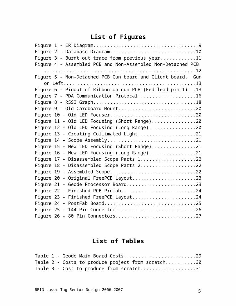
List of FiguresFigure 1 - ER Diagram........................................................................................................9Figure 2 - Database Diagram.............................................................................................10Figure 3 - Burnt out trace from previous year...................................................................11Figure 4 - Assembled PCB and Non-Assembled Non-Detached PCB..............................12Figure 5 - Non-Detached PCB Gun board and Client board. Gun on Left......................13Figure 6 - Pinout of Ribbon on gun PCB (Red lead pin 1)................................................13Figure 7 - PDA Communication Protocal.........................................................................16Figure 8 - RSSI Graph.......................................................................................................18Figure 9 - Old Cardboard Mount.......................................................................................20Figure 10 - Old LED Focuser............................................................................................20Figure 11 - Old LED Focusing (Short Range)...................................................................20Figure 12 - Old LED Focusing (Long Range)...................................................................20Figure 13 - Creating Collimated Light..............................................................................21Figure 14 - Scope Assembly..............................................................................................21Figure 15 - New LED Focusing (Short Range).................................................................21Figure 16 - New LED Focusing (Long Range).................................................................21Figure 17 - Disassembled Scope Parts 1............................................................................22Figure 18 - Disassembled Scope Parts 2............................................................................22Figure 19 - Assembled Scope............................................................................................22Figure 20 - Original FreePCB Layout...............................................................................23Figure 21 - Geode Processor Board...................................................................................23Figure 22 - Finished PCB Prefab.......................................................................................24Figure 23 - Finished FreePCB Layout...............................................................................24Figure 24 - PostFab Board.................................................................................................25Figure 25 - 144 Pin Connector...........................................................................................26Figure 26 - 80 Pin Connectors...........................................................................................27
List of Tables
Table 1 - Geode Main Board Costs...................................................................................29Table 2 - Costs to produce project from scratch................................................................30Table 3 - Cost to produce from scratch.............................................................................31
RFID Laser Tag Senior Design 2006-2007 4
Project Overview
The goal of this project is to develop a system utilizing radio frequency identification tags or RFID tags to enhance laser tag. The final implementation of this project should be able to track player movements and actions across a grid of RFID tags and based upon these movements have the players interact in various types of games. Teams or players can win games by staying in certain zones for a specific amount of time or by accomplishing specific objectives. This adds a dimension of play that was previously unavailable in laser tag and mimics modern games that our target audience is very familiar with. This project is a continuation of a project from a 2005 senior design team. Our goals have been primarily refining and building upon their fundamental design.
In order to accomplish the task of tracking player movements the design that was settled on by last years team was to place active RFID tags in a grid spaced approximately every 5-10 feet. The players then had specially equipped laser tag guns that were outfitted with a RFID tag reader. As the players move across the grid of tags the RFID reader picks up its surrounding tags in order to determine the player position on the grid. The challenges of this task are that the location is calculated based upon a RSSI value from each tag essentially each tags signal strength. The RSSI values however can fluctuate significantly based upon the environment and age of tag. Reflections from various surfaces on the playing field can significantly impact the RFID readers perceived signal strength. The difference in tags signal strength is also not necessarily detectable given our desired resolution of approximately 3 meters. This has proven to be one of our largest hurdles in our overall design and possible solutions will be addressed later in this report.
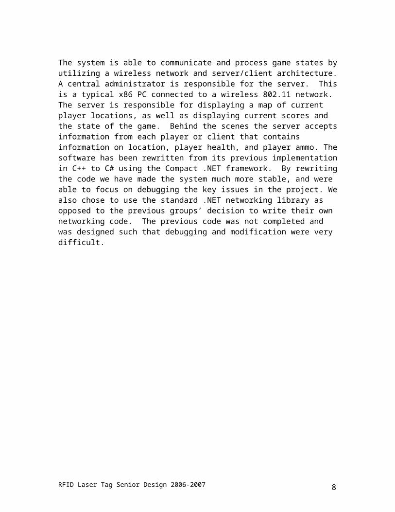
The system is able to communicate and process game states by utilizing a wireless network and server/client architecture. A central administrator is responsible for the server. This is a typical x86 PC connected to a wireless 802.11 network. The server is responsible for displaying a map of current player locations, as well as displaying current scores and the state of the game. Behind the scenes the server accepts information from each player or client that contains information on location, player health, and player ammo. The software has been rewritten from its previous implementation in C++ to C# using the Compact .NET framework. By rewriting the code we have made the system much more stable, and were able to focus on debugging the key issues in the project. We also chose to use the standard .NET networking library as opposed to the previous groups’ decision to write their own networking code. The previous code was not completed and was designed such that debugging and modification were very difficult.
RFID Laser Tag Senior Design 2006-2007 5

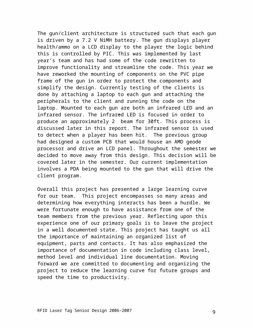
The gun/client architecture is structured such that each gun is driven by a 7.2 V NiMH battery. The gun displays player health/ammo on a LCD display to the player the logic behind this is controlled by PIC. This was implemented by last year’s team and has had some of the code rewritten to improve functionality and streamline the code. This year we have reworked the mounting of components on the PVC pipe frame of the gun in order to protect the components and simplify the design. Currently testing of the clients is done by attaching a laptop to each gun and attaching the peripherals to the client and running the code on the laptop. Mounted to each gun are both an infrared LED and an infrared sensor. The infrared LED is focused in order to produce an approximately 2” beam for 30ft. This process is discussed later in this report. The infrared sensor is used to detect when a player has been hit. The previous group had designed a custom PCB that would house an AMD geode processor and drive an LCD panel. Throughout the semester we decided to move away from this design. This decision will be covered later in the semester. Our current implementation involves a PDA being mounted to the gun that will drive the client program.
Overall this project has presented a large learning curve for our team. This project encompasses so many areas and determining how everything interacts has been a hurdle. We were fortunate enough to have assistance from one of the team members from the previous year. Reflecting upon this experience one of our primary goals is to leave the project in a well documented state. This project has taught us all the importance of maintaining an organized list of equipment, parts and contacts. It has also emphasized the importance of documentation in code including class level, method level and individual line documentation. Moving forward we are committed to documenting and organizing the project to reduce the learning curve for future groups and speed the time to productivity.
RFID Laser Tag Senior Design 2006-2007 6

Work in Progress
Software Design
The previous group decided to develop on an x86 compatible system using Linux C++ and a SDL graphics system. This lead to many problems including increased development time, increased power, inability to expand, and many more. So we decided to switch to a Windows mobile based system using the .NET Compact framework. This decreased development time drastically, because it is much easier to program in higher level languages. The power consumption on an x86 platform would have only allowed for short amounts of game play, while the windows mobile environment allows for hours of battery life. To expand this system it is possible to use an off the shelf PDA and cable, which is much easier and cheaper than custom motherboards and LCD screens.
.Net Advantages
Backed by Microsoft Large development community Lots of standard libraries Speed of programming Code Reuse (Client and Server)
Windows Mobile Challenges
Our original plan for the client program involved an ASP.Net web page to display all the information, we thought this would take most of the strain off the PDA and simply require it to view a web page. This plan failed due to the lack of power from the windows mobile browsers, none of them supported the CSS and java script functionality we needed. Then we thought that the .Net Compact framework would have the same functionality as the .Net framework, but this proved not to be true. Many of the basic features of the included windows forms controls had been changed, such as background image support and event monitoring order. This forced us to use slightly different code on the client and server.
RFID Laser Tag Senior Design 2006-2007 7
Version Control
For ease of development we have placed all of our code and documentation into SVN repository. This allows all of us to make and track changes easily without the hassle of merging all of our changes every time we wish to build. There are four nodes under the trunk node, client, server, calibrator, and documentation. The client and server node both contain a Shared node, the client node's shared node does not actually exist in version control but all code changes to that node are pushed and pulled to and from the server node's shared node. This affectively creates a shared node which both projects can edit and both projects will get the changes. This is done by defining a SVN property called external in the client node, which contains two items per line, the name of the node you wish to create and the path to the external node. If there are spaces in your path you must replace them with HTML style “%20” spaces.
Software Rework
The learning curve on this project was very steep to begin. The goals between this year’s team and last year’s team were very different. Last years team was focused more on producing a proof of concept. This seems to have led to a lot of changes in the design of the system and a lack of solid documentation the existence of ambiguous/arbitrary error codes lead to longer debugging and code evaluation time. The lack of access to their subversion repository and last minute changes done at E-Days last year resulted in an inconsistent software state. Without the assistance of a team member from last year we were unaware of small changes that would have prevented the system from working properly. This assisted in our decision to redesign the code using the .NET framework and redesign essentially the entire code base.
Client / Server Improvements
The original client / server program experienced many random errors and was very unpredictable. Typical client connections lasted less than a minute. This was possibly due to the custom networking code that was chosen rather than utilizing a standard networking library.
The client has now been redesigned to display a map of the game environment and display the player and other teammates on the screen. Because we are implementing this on a PDA we also have the ability to tap the screen and show player statistics. The map display control is shared between the client and the server and many other classes have been shared between the two programs. This has increased the maintainability of the code dramatically. We have also made significant strides to increase the amount of commenting done in the code, as opposed to the previous year’s implementation. This will make future modifications and debugging much quicker and easier.
RFID Laser Tag Senior Design 2006-2007 8
Database Design
The current design utilizes a relational database to store all of the needed information in the system. This includes the grid of tags used to compute the nearest neighbor algorithm, the player information and team information. This design was computed through a E-R diagram which is shown in Figure 1. The resulting tables are shown in Figure 2. The current implementation makes use of a Microsoft SQL Express 2005 database. This is currently being run on the game server and allows both the server and clients to access it.
The software has been written in such a way that all of the methods to access the database are kept in one class dbMgr. This class is shared between the client and the server for consistency and maintainability. Each method in the class takes a set of parameters and then passes these to a stored procedure which is stored on the database.
The Maps table stores a field called gridID which allows the user to select from multiple maps stored in the table. The table then stores the x,y coordinates of specific points on the grid. This is followed by 8 RSSI values which are used in the nearest neighbor algorithm. Finally, the table stores the x,y coordinates for any available neighbors for each point. The primary key of this table is the Grid ID, LocX, LocY.
The Players table stores each player’s PlayerID, which is used to uniquely identify the player. Each player has the common attributes of player name, health, armor, clips, rounds and current x,y position. Each player is also associated with a team through a TeamID field. Each player also has a status attribute which is used to indicate various player statuses such as “alive”, “dead”, “VIP”, “hostage”. Each player has a selected field which is currently being utilized to change the background color of players on the display when the game admin selects them. The primary key of this table is PlayerID.
The Teams table stores a Team ID, Team Name and background color. The background color is used to determine the background color for each team on the team display. The primary key of this table is TeamID.
Figure 1 - ER Diagram
RFID Laser Tag Senior Design 2006-2007 9

Figure 2 - Database Diagram
RFID Laser Tag Senior Design 2006-2007 10

Gun Overhaul
Initial plans for the project were largely focused on software concerns: PIC Basic PRO code efficiency, more accurate location tracking, game design, and interfaces. The largest problems we faced while coding always led back to a hardware concern. It was with this motivation that a Gun overhaul was deemed necessary, to provide a more robust work environment in which to focus purely on software.
During the course of the overhaul, we touched on the following areas: modularizing the guns to prevent cable breakage / wear-and-tear, manufacturing more working guns for proper simulation, finding replacement parts, documenting gun hardware, and calibrating the IR LEDs.
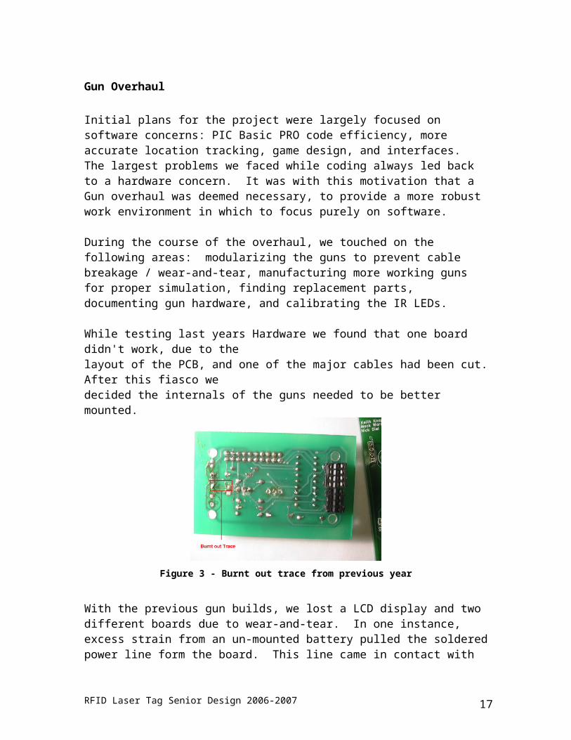
While testing last years Hardware we found that one board didn't work, due to the layout of the PCB, and one of the major cables had been cut. After this fiasco we decided the internals of the guns needed to be better mounted.
Figure 3 - Burnt out trace from previous year
With the previous gun builds, we lost a LCD display and two different boards due to wear-and-tear. In one instance, excess strain from an un-mounted battery pulled the soldered power line form the board. This line came in contact with the metal backplane of the voltage regulator, causing a short which rendered the board and the LCD useless. To avert this problem, we fixed the guns with a new barrel; a 7 ½” 3” PVC extension which we used to house the battery pack. The battery is mounted securely within the barrel, and should not need to be removed. Two inches from the back of the barrel we drilled a hole large enough for the battery connector to come through. By making a similar hole in the handle part of the gun, this allowed the connector to be attached / detached externally. This allowed for the barrel-battery to be removed for charging without disassembling the gun. The serial port’s wires were very fragile and dangling, and snapped several times. By mounting the serial port in the handle of the gun, above the trigger, we were able to remove all strain from the connector itself. By doing this, the USB -> serial connector could be attached or removed as needed, it is out of the way, and different clients can be attached or removed from the gun without fear of breakage. The LCD plugs into the back of the gun board, and was mounted through the gun cap.
RFID Laser Tag Senior Design 2006-2007 11

Previously the non-plugin side was floating. In order to prevent this, placing two nylon spacers between LCD and board around the screw mounts secured this problem, and keeps the connection sturdy. Finally, a pin is put in place on the top side of the gun to keep the board containing cap on the gun.
At the start of the project we were told there were two complete working guns, and full hardware for an additional two. In reality one worked "fully" and we had working parts for one additional gun.
Due to the afore mentioned disasters we had to order two additional boards, and three additional LCD screens in order to get our goal of four working guns accomplished. Unfortunately the LCD was no longer being produced by Hantronix, so a new one of the same form factor had to be found. The closest one that could be found used a 14 pin interface instead of a 16 pin interface, and the dimensions of the holes for mounting was slightly different. After receiving the order we found that it would plug into the 16 pin interface and work just fine.
Figure 4 - Assembled PCB and Non-Assembled Non-Detached PCB
During the course of this semester, after breakage, part shortages, and re-design, we are left with 4 working gun boards, compared to the one we started with. Three of these were soldered and assembled this year. This includes making new IR sensor boards. When the client PCB board was ordered, gun boards were also ordered on the same block. This leaves us currently with enough PCB gun boards for 4 – 5 more guns. The cleanest, but most time consuming way we were able to separate the two boards was with a razor. Use the razor to file off enough of a groove, then the boards can be snapped apart. A very thin bladed hacksaw also will work, although not quite as cleanly.
RFID Laser Tag Senior Design 2006-2007 12

Figure 5 - Non-Detached PCB Gun board and Client board. Gun on Left
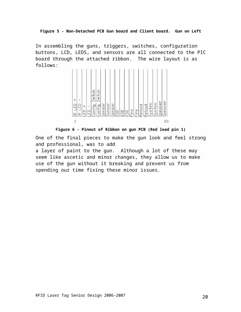
In assembling the guns, triggers, switches, configuration buttons, LCD, LEDS, and sensors are all connected to the PIC board through the attached ribbon. The wire layout is as follows:
Figure 6 - Pinout of Ribbon on gun PCB (Red lead pin 1)
One of the final pieces to make the gun look and feel strong and professional, was to add a layer of paint to the gun. Although a lot of these may seem like ascetic and minor changes, they allow us to make use of the gun without it breaking and prevent us from spending our time fixing these minor issues.
RFID Laser Tag Senior Design 2006-2007 13

Gun Protocol Overview
The guns and sensors of the laser tag system are designed to have the sender and sensors in the same system to simplify the overall system by not making the client responsible to interface with the guns and sensors. The guns and sensors are connected to a microcontroller which sends the bits through an IR LED and monitors the sensors made up of IR decoders that receive the IR bits sent by other guns. The IR bits are encoded by bit length encoding. The bits are modulated by a 40 kHz carrier wave. The gun sends two data bytes. The first is the team and the player of the shooter. The first three bits are the team and the last five are the player. For example, 0010011 would be team 1 and player 3. The second data-byte contains the hit points of the firing gun. For example if the second byte is 00011001, which is 25 in decimal, the hit will reduce the hit player’s health by 25 points.
Variable Configuration
The guns have a great deal of functionality. The guns have nine configurable variables. These variables are: myteam, myplayer, rounds, clips, fire_sel, rel_time, friend_fire, kevlar, and health. Each variable have two different ways of being configured. The first way, the guns have a configuration switch; this is a toggle switch that when in the on position the menu button will be able to access the player restart menu and the configuration menu. When in the off position the configuration menu is not reachable. In the configuration menu the trigger changes the values of the selected variable, and the configuration button moves to the next variable. To leave the configuration menu the trigger button should be pressed in the save screen of the configuration menu. If the first way of configuring the variables via the configuration menu is not needed, the configuration switch can be removed from the circuit, which will effectively leave the switch in the off position permanently. The second way the variables can be configured is by the client. The gun is interfaced to the client through the serial port. Now each variable will be described and what values it can be set to.
Myteam is self descriptive; its value is the team to which the gun belongs. What is not clear is there are seven teams 00100000, 01000000, 01100000, 10000000, 10100000, 11000000, and 11100000. So to set these values through the client the team value must be set to the corresponding decimal value: 32, 64, 96, 128, 160, 192, and 224 respectively. When programming the gun from the client setting it to 0 will simply not change the previous value.
Myplayer is the player id of the player’s gun. This value can be set between 31 and 1. There is no special encoding for this variable the client can set it to any value between 1 and 31. When programming the gun from the client setting it to 0 will simply not change the previous value.
RFID Laser Tag Senior Design 2006-2007 14

Rounds is the number of rounds in a clip. Rounds can be set from 1 to 251 and 251 is unlimited. When programming the gun from the client setting it to 255 will simply not change the previous value.Clips is the number of clips the player has. The number of clips can be set from 1 to 99. The total number of ammo is rounds * clips. When programming the gun from the client setting it to 255 will simply not change the previous value.
Fire_sel stands for fire select. There are two settings 0 and 1. 0 is semi-automatic fire, 1 is automatic fire. When programming the gun from the client setting it to 255 will simply not change the previous value.
Rel_time stands for reload time. This is the amount of time in seconds reload will take. Reload time can be set from 1 to 30 seconds. When programming the gun from the client setting it to 255 will simply not change the previous value.
Friend_fire stands for friendly fire. This determines if players on the same team can hit each other or not. This can be set to 0 and 1. If friend_fire is set to 1 players can hit each other. When programming the gun from the client setting it to 255 will simply not change the previous value.
Kevlar is body armor. This will reduce the hit points of one shot by half. Every time a player is hit the shield value will be reduced by one. When programming the gun from the client setting it to 255 will simply not change the previous value.
Health is the amount of health points a player has. Health can be set from 1 to 250. 100 is the normal setting. When programming the gun from the client setting it to 255 will simply not change the previous value.
On power up, the gun waits for a configuration packet. Once received, it waits for the game to start. This is initiated by the PDA sending the same configuration packet. This allows a packet or two to be dropped but still have proper functionality. The gun then sends a packet containing its current status anytime it again receives that same packet.
RFID Laser Tag Senior Design 2006-2007 15

The following is the communication protocol the PIC abides to:
Figure 7 - PDA Communication Protocal
RFID Laser Tag Senior Design 2006-2007 16
Nearest Neighbor Algorithm
Introduction
In order to add the radar element to the laser tag game a location tracking scheme had to be implemented. In addition it was recognized that today’s active RFID tags are relatively inexpensive and the industry has a desire to be able to track their location. So with this in mind it was decided to build a location tracking scheme based on active RFID tags. In order to scale to a large area inexpensively the active RFID tags were placed throughout the room while every player’s gun would have a RFID reader. This is contract to traditional location tracking where each moving object has a tag attached to it and readers are placed through environment, though it was felt that this would not scale well finically in a large area where the number of players per square foot is relatively low.
Last Year Implementation
Last year’s implementation attempted to use a triangulation method to determine the location of a player. During actual use it was found that triangulation was returning results that were unacceptable for laser tag. In a room the size of 20 feet by 50 feet triangulation could not determine even the side of the room you are on accurately. In addition, due the nature of the floating point operations in the triangulation algorithm there are infinite number of locations one player could be in and one would never be in the exact same place twice, even if the player has not moved. Also one of the main reasons triangulation failed is due to the high frequency of the active RFID tags, 433MHz, which can reflect off of numerous things increasing your signal strength as one gets farther away from the tag. With all of these issues it was decided a new location tracking scheme was needed.
This Year Implementation
First it was decided to use the existing RFID readers and RFID tags due mainly to financial constraints. Second after doing research it was decided we could potentially get better results if we switch to a nearest neighbor algorithm to determine a players location. The research we did indicated that the best location tracking schemes in academia used a nearest neighbor algorithm in addition to different types of filters and other statistical movement prediction techniques. The best results they were able to achieve were on the order of 3 to 5 meters accuracy. While 3 to 5 meters accuracy is not sufficient for a small laser tag arena it would be a giant improvement over the previous implementation using triangulation.
It was decided to start out with just a basic nearest neighbor algorithm and a moving average filter for the RSSI values. In order to accomplish the nearest neighbor algorithm a calibration phase was needed. This calibration phase built a table of X,Y coordinates that describes what the RSSI values look like from the tags in range. During real-time
RFID Laser Tag Senior Design 2006-2007 17

play the nearest neighbor algorithm would determine based on the current readings which X,Y coordinate it best matches and that would be the location of the payer.
In terms of software, a calibration program was written to make it possible to quickly calibrate a playing environment. The client software had a moving average filter implemented for all incoming RSSI values in addition it would run the nearest neighbor algorithm to find the players location. A SQL table was used to transport the calibration table between the calibration program and the client.
Results
During implementation it was found we were not achieving the results we wanted. Our accuracy was found to be on the order of 5 to 7 meters, which is unacceptable for influencing a laser tag game. We also identified several reasons for our poor performance. These include issues with both our equipment and our algorithm.
One of the main problems with our equipment was the simplicity of the RFID reader. The reader’s main purpose is to read a tag’s ID, though it happens to also report an RSSI value. It is felt that since the reader’s main purpose is not to report RSSI values the values we do get are rather imprecise. One of the main side affects of this is there are many missed readings from individual tags. Below is a graph that shows readings of a single tag while staying in a fixed location.
Figure 8 - RSSI Graph
In addition to the missed readings, a tags RSSI value could vary little through out a laser tag environment making it hard to distinguish between different points. Below is a topology maps showing the RSSI values of a tag through out the entire environment.
Our algorithm was incapable of compensating for the side effects of the equipment used. Our algorithm had a sophisticated mechanism to detect missed readings and because of the large number of missed readings, this resulted in all of the RSSI values being averaged down and making it harder to distinguish between different locations. Also the
RFID Laser Tag Senior Design 2006-2007 18

nearest neighbor algorithm works best when different tags are in range and or tags have must higher RSSI values at different location. Since in our small environment a tags RSSI value could decrease very little over the playing area and was generally in range through out the entire environment, distinguishing locations was very hard to do.
The side effects of our equipment have a couple of positive benefits for location tracking. First the equipment is relatively inexpensive and makes it scale very well in a large playing area especially where the number of players per square foot is low. The tags have a large range which means in a large area you do not need as many of them as you would with other tags. The reader is small and light adding very little mass and size of the gun. The accuracy of our system would be sufficient in a very large playing area giving you accurate information where people are within 5-7 meters.
Future Work
There are several approaches that can be made to improve our accuracy. The first involves improving the algorithm to compensate for the side effects of our equipment, while we haven’t identified any specific solutions we have identified several problems that should be addressed. Ideas such as a decaying method of for missed readings could improve the current algorithm, but further research is needed to be done first.
The second area of improvement is a change of equipment. A reader that is capable of providing more accurate RSSI values in addition to missing fewer readings could greatly improve accuracy. Also tags with less transmit power would be highly beneficial for a small playing field, though this would prove to be less beneficial in a large playing area.
While doing our initial research we found many academia papers were using RFID tags that work on an 802.11b/g infrastructure. We feel this should be investigated as a potential solution for our project. This is because there has been much research done with this equipment in terms of location tracking and because our clients use 802.11b for communication so wireless infrastructure is already needed.
RFID Laser Tag Senior Design 2006-2007 19
Infrared LED Focusing
To test the IR LED focusing, we modified a Logitech webcam by removing the RED IR filter, and inserting a visual light filter. This allowed us to take picture and video of exactly what our beams looked like.
What we found was that the old system worked decently well. The problem was its mounting. The previous mounting involved setting the LED in a cardboard back plate as seen in Figure 10. It was very difficult to actually aim the beam, but the size of the beam was roughly inline with specifications. At 50 Ft, the size of the beam was roughly 16” in diameter. At 10 Ft, it was roughly 4” in diameter, as seen in Figures 12 and 13. The energy concentration was more scattered than we would have liked, though.
Figure 9 - Old Cardboard Mount Figure 10 - Old LED Focuser
Figure 11 - Old LED Focusing (Short Range)
Figure 12 - Old LED Focusing (Long Range)
RFID Laser Tag Senior Design 2006-2007 20
The problem we see here is a variance in the beam that changes directly with distance. Theoretically, placing a point source of light at the focal point of a lens should yield a perfectly collimated beam of light, Figure 14. In practice, this is very hard to reproduce, especially with only PVC fittings to work with.
Figure 13 - Creating Collimated Light
Figure 14 - Scope Assembly
To get a better mount and focusing, we used a 48mm lens with a 4” focal point. This smaller lense allowed us to form a scope that would be mounted on top of the gun, and can be more easily aligned. The LED is mounted in a holder in the center of a ¾” cap. This cap goes into a series of connectors. This then fits into a 1.5” PVC pipe. The lens is placed on the end, and held on with a coupler. This setup can be seen in Figures 18-20. This mounting can be seen in Figures .The results were very satisfactory, with a very strong energy concentration, as seen in Figures 16 and 17.
Figure 15 - New LED Focusing (Short Range)
Figure 16 - New LED Focusing (Long Range)
RFID Laser Tag Senior Design 2006-2007 21

Figure 17 - Disassembled Scope Parts 1 Figure 18 - Disassembled Scope Parts 2
Figure 19 - Assembled Scope
RFID Laser Tag Senior Design 2006-2007 22

PCB Board Design
The platform that was used last semester was based on the Geode processor. Although the system was never implemented and abandoned, a good portion of the year was spent on the design of this system. The previous year designed a netlist for the motherboard and connections to the peripherals. This year, the netlist was taken to the next step and designed for a 4 layer PCB. After manufacturing and weeks of testing, it was found that the original netlist was flawed. The platform was then changed to use PDA’s instead of the Geode system. This section covers the printed circuit board design and manufacturing for the RFID laser tag system.
There are two boards used in this system, the gun board and the motherboard for the Geode module. The gun board had been developed and manufactured in past semesters. The design process had begun on the Geode board last semester and continued this year. Here the requirements, design and manufacturing process are going to be discussed regarding the Geode module.
Figure 20 - Original FreePCB Layout Figure 21 - Geode Processor Board
The board design was based off of the designs developed by last years, 2005, senior design team. This board was designed to function as the motherboard for the geode processor. The Geode system was meant to be implemented in the guns along with the gun board. The board and processor was supposed to run the client software, communicate with the main server and show data on a TFT display mounted to the gun. A picture of the Geode processor board may be seen in figure 1. The supported devices are listed as two USB ports, two serial ports, audio and video. The size of the board was also taken into consideration during the design process. The circuits on the board are spread over four layers. The top and bottom layer are signal layers and the inner two layers are power supply and ground. The board was designed to mount on the guns along
RFID Laser Tag Senior Design 2006-2007 23

with the LCD display. The PCB had been designed in FreePCB, a free printed circuit board utility that is distributed under GPL. This software was used because it was free and has the ability to generate gerber files that are used by the PCB manufacturer Advanced Circuits. One goal of this years design team was to continue the development process on this board to the point where the board can be implemented in the proof of concept.
Due to the limited documentation on the designs, the first step was to examine the board designs to determine what needed to be done to move the board forward in the design process. Last years team had used schematics from Advantech to base their circuit designs from. These same schematics were utilized to check and verify some of the circuits on the designs. The exact point where the last team had left off was not known. It was found that the designs were in a rough state. A schematic from FreePCB may be seen in figure 2. Most of the components were placed, but the clearances between parts needed to be adjusted and certain parts used in the designs were no longer available. A new BOM was started to help determine the part availability and quantity. Replacement parts were found and the layout was changed to work with the new footprints. Some minor parts needed to be changed because of limited availability. Once all the parts were found and their availability was verified, the designs were analyzed.
Figure 22 - Finished PCB Prefab Figure 23 - Finished FreePCB Layout
The next step in the design process was to analyze existing designs and to do final layout. Like stated earlier, the designs were rough. A couple of design rules were used in the final layout. First, a basic rule is to limit the traces to have changes in direction of 45 degrees maximum. A 90 degree corner may be realized by combining two 45 degree corners. The reason for this is that a 90 degree angle on a trace may look like a discontinuity. The traces were close to their final positions, but there were places that needed further design considerations. Some of the traces had 90 degree direction changes. These needed to be changed to multiple 45 degree changes as to limit signal degradation. A Second rule that was followed was to limit the size of loops that the traces make. A
RFID Laser Tag Senior Design 2006-2007 24

loop is basically an antenna. If there is a loop close to another trace or input, it can generate noise in that signal. This was accomplished by carefully laying out the traces in a manner such that the loop sizes were limited. A third rule to the layout was to connect the signal circuits ground to the power ground at one point. The reason for this is that transients on power grounds can be much greater than on signal grounds. Signal circuits usually don’t have the capability to handle the magnitude of the transients seen on power circuits. This was also accomplished in the PCB by careful layout. The new PCB design may be seen in figure 3. It should be noted that the layout differences are hardly noticeable, but the functional differences quite large. The PCB manufacturer, Advanced Circuits was chosen to build the printed circuit board. This company does not offer blind vias in their products. Because of this, the ground planes and the supply planes had to be modified so that any vias didn’t accidentally cause a short. This was done by making cut out areas in the planes to allow proper spacing for the vias. The company Advanced Circuits, the PCB manufacturer, has an online layout checking tool that was used to determine if the designs could be manufactured. This tool was utilized to make sure the board would be made and operate to specifications. The designs were submitted to Advanced Circuits in Denver, Colorado to be built. The manufactured PCB may be seen in figure 4. The components for the board were ordered from various online companies such as Digikey and Mouser. The costs for the board and the components may be seen in the budget section of this report. After the PCB was manufactured the components had to be attached.
Figure 24 - PostFab Board
The next step in the development process was to assemble the Geode motherboard. Most of the components of the board were surface mount with a very fine pitch. Outside companies were researched for board assembly. The companies all required an excess of parts and at least a week for manufacturing. This and the cost motivated the team to hand solder the PCB. Over a period of a week the components were attached to the board. A magnifying stand along with a fine tipped soldering iron was used to solder the PCB. The first step in the process was to tin the pads. This is placing a small amount of solder to
RFID Laser Tag Senior Design 2006-2007 25

each pad so that it is easier to attach the components. A little solder was melted onto the tip of the iron. Then the pad was heated by the iron. The solder on the tip flows and covers the pad. The part was then placed on the pads. Each pin on the part was then touched to heat the pin and melt the solder to attach the part. This process worked well. Some of the finer pitch parts were much more difficult to work with. For these parts care had to be taken to avoid bridging the pins. After each part was attached, the contacts were visually inspected to ensure conduction was possible and that bridging had been avoided. After the system was built it was tested and found to be inoperable as will be explained in the next session.
Geode Motherboard Finalization
The current designs for the motherboard utilizing the geode processor are still in need of work. The current status of the board is inoperable. The problems stem from an incomplete design and not design errors. The circuits currently implemented in the designs have been reviewed and don’t seem to have any problems. As is, the board will not post. There are a couple of actions that need to be taken to resolve this issue. The first would be to correctly terminate unused signals on the board. A second action is to verify that the bios is configured for the design specifications of the board. In performing these actions, it is believed that this board will perform to expectations.
One problem found with the current designs is that there are signals floating from the Geode processor that need to be correctly terminated. The netlist listed the signals not being utilized by the other systems to be left floating. This includes the pci bus and some communications that have been left floating. On the pci system, there are a couple of reset and data hold signals that have been left floating. It is believed that this is one reason as to why the bios is not posting. If there are active reset signals on the bus when the bios is trying to initialize peripheral devices, then the process will not complete and the processor will not post. The pins whose signals need to be pulled up or down and their signal names are listed at the end of this document.
Figure 25 - 144 Pin Connector
This fix will require the redesign of the board. This will be involved due to the number of signals to be added and rerouted. There is available space on the back side of the current board. It is suggested running the signals through a series zero ohm resistor to either signal ground or 3.3 volt vcc. The current signals may need to be rerouted to make space for the added traces and resistors. The picture to the right shows the 144 pin connector. The pads and traces in red will have to be manipulated to terminate the signals correctly. As seen above, there is little room,
RFID Laser Tag Senior Design 2006-2007 26

but it is possible if the traces are moved and modified to make space for the new traces. The figure below is the 80 pin header. This will be the difficult section to reroute simply because the area is already congested. It is possible though. As stated earlier, there is space available on the back of the motherboard for the signals and traces. The layout may have to be creative.
Figure 26 - 80 Pin Connectors
Fortunately there are only 11 signals on this header that need to be terminated. The rest of them may be left floating. It is important to not move the header as the location must be the same to interface with the processor. If it is moved, it may not be in the right location to connect to the processor board. Use of a R0402 footprint and resistor would work as these are small enough that proper spacing may be obtained. The traces should be rerouted to that they will come straight into the pads and still have enough room for the resistors. The library included in this directory contains data sheets on chips used in the designs. These may be utilized in further designs or to locate replacement parts in case these parts become obsolete. In performing the actions listed, I believe the system would be in working order.
RFID Laser Tag Senior Design 2006-2007 27

Project Budget and Costs – Custom x86 Implementation
The following budget and cost analysis covers our introduction to the project, and first reworks of its design. We will then go over our new framework, and its improved cost advantages.
As we began working on this project it became quite clear we were finishing the proof of concept started last year. With this in mind we were not able to come up with a definitive budget as we did not know what exactly was needed. As we started out we did have a set of immediate goals that needed to be accomplished and with those goals there was a known cost from last year associated with them. With this information Dr. Chen gave us the go ahead to order these pieces. Other than that as things came up we worked with Dr. Chen to decide if a purchase was necessary. Included in this task we had to find suppliers who were willing to sell us the parts we need at low quantities. This alone proved to be quite time consuming. With a better understanding of the project and a better understanding of the ordering process we are able to control and budget our remaining expenses.
Immediately we had to figure out how to assemble and order the Geode printed circuit board upon completion of the design. This included figuring out what parts the board needed, how and who to order the broad from, and what tools were needed. Last years group had identified a company in Denver that produces printed circuit boards that they had used for the gun board. It was determined that we would continue using them with their standard school discount. Also from last year we were given a bill of materials for the geode board that we could use. Finally based on the experience of the group members we were able to identify some basic tools we would need, most importantly a quality soldering iron and rework station.
With the PCB (printed circuit board) manufacture determined we had to work with the BOM (bill of materials) given to us. We started out by first checking for completion of the BOM against the boards design. Once we updated the BOM and verified the BOM was complete we next had to start tracking down the parts. Many of the parts on the original BOM were non descriptive and we had to use the board’s design to track down the exact part we needed. Or the part that was listed was too descriptive (i.e. it was tied to a specific part manufacture) and we had to figure out the boarder parts name to find alternatives for ordering them. Once we knew what parts we needed we started tracking down a source to order them from. We relied on two parts distributors, Mouser and Digikey. Both were chosen as they offer a wide variety of parts and are able to sell most of the parts in single or small quantities. Between these two companies we were able to obtain virtually all of the passive components and the ICs that would go on to the Geode board, with the exception of one IC. This IC we were able to get some free samples from the IC manufacture directly.
From there we need to obtain the proper tools in order to be able to assemble this board. The board had a number of 0402 sized components in addition the fine pitched ICs. In
RFID Laser Tag Senior Design 2006-2007 28
order to be able to successfully solder these components you need a proper soldering iron and a hot air rework station. After some research it was determined that a soldering iron/hot air rework station sold by SparkFun.com would sufficient while not be too expensive. Many of the solutions we looked at very expensive and capable of more than we needed. The soldering station we found matched our requirements and was priced reasonably. The rest of the tools we needed were readily available to us either through the school or through our personnel collection.
Below is a table summarizing the costs associated with the producing the Geode board.
Geode Board AssemblyPCB Manufacturing $358.00Passive components and ICs $463.00Tools and equipment $180.00
Subtotal: $1001.00
Gun RefinementsPVC Piping $40.00Misc. Hardware $60.00
Subtotal: $100.00Table 1 - Geode Main Board Costs
The Geode board was by far the most expensive endeavor of the semester. Many of the other pieces were present when we started this semester. These include the Geode processor, the LCD panels, the gun and their PCB boards with parts. Any additional purchases that were made were either for improving the existing gun or making more guns. These small purchases included additional PVC tubing to build a new gun, new lenses to try out different focusing mechanisms, additional IR LEDs to test the response of the different LEDs, and additional components to build more gun boards.
RFID Laser Tag Senior Design 2006-2007 29

Projected Costs of Proof of Concept
Since most of expensive parts were already present when we started, our project budget and costs does not detail the actual cost to reproduce this proof of concept. The costs would be broken down into three categories. First would be the infrastructure costs would consist of the RFID tags that would need to be placed around the playing field and the server that would be needed to run the game. The second category would the gun which is listed as a cost of per gun and you will need one gun per player. The final category is equipment that would be needed in order to assemble everything.
Below we detail the costs associated with actually reproducing this project from scratch.
InfrastructureRFID Tags (listed for 15 tags) $75.00Server $800.00
Subtotal: $875.00
Gun (listed as a per gun cost)Geode Board $150.00Geode Processor $200.00RFID Reader $100.00640x480 LCD Panel $300.00Gun Board + Parts $50.00PVC Tubing $10.00Optics $10.00
Subtotal: $1170.00
EquipmentSoldering Station $170.00Test and Measurement Tools $1000.00Miscellaneous Tools $200.00
Subtotal: $1370.00Grand Total (with 4 guns): $6925.00
Table 2 - Costs to produce project from scratch
RFID Laser Tag Senior Design 2006-2007 30

Project Budget and Costs – .NET PDA Implementation
With the start our second semester’s work, many, many things changed in our entire design. We moved away from the custom PCB board design and associated Geode to implement the design on PDAs. This removes the board costs and parts costs. Also, it made for a robust system without the countless man hours of testing and debugging. The manufacturing costs and infrastructure costs would likely stay the same, but due to the greater simplicity of a pre-built and tested PDA, Test and Measurement Tool costs could probably be greatly decreased. Much of this cost and time could then be focused towards the software and communications concerns.
InfrastructureRFID Tags (listed for 15 tags) $75.00Server $800.00
Subtotal: $875.00
Gun (listed as a per gun cost)PDA $350PDA – Serial cable $15.00Gun Board + Parts $50.00PVC Tubing $10.00Optics $10.00Other cables, connectors $15.00
Subtotal: $450.00
EquipmentSoldering Station $170.00Miscellaneous Tools $200.00
Subtotal: $370.00
Grand Total (with 4 guns): $3045.00Table 3 - Cost to produce from scratch
Our newest design and strategy have overall greatly decreased projected startup and implementation costs for a system containing four guns, by roughly one half. It can be seen most of this cost savings comes from implementing the design on a pre-manufactured PDA, which also reduces the overall amount of tools we would need to properly test and debug our own motherboard. Software costs would stay the same, if not decrease utilizing a Windows based system using C#.
RFID Laser Tag Senior Design 2006-2007 31

Projected Market
The market for this project is primarily corporate and independent laser tag suppliers, field operators and amusement parks. Current laser tag solutions provide the laser tag guns, base stations and communications between the various components. Our project will allow team based interaction on a level which was previously unimaginable. The ability to view your teammate’s locations on the on-gun LCD provides an experience similar to that provided by many computer games. The target audiences of the majority of laser tag arenas is very familiar with these types of games and are familiar with the ability to see there teammate’s and plan strategies based on this information. Ideally this would draw more players and promote a more competitive team based atmosphere.
A typical player set up costs approximately $1000-$2000 per unit. In order to develop a fully functional laser tag arena the approximate cost in laser tag equipment alone is $32,000-$64,000. Our goal is to keep the cost of the equipment and gun within this range so that when modified to withstand the rigors of daily use is still affordable to the majority of laser tag centers.
A further potential use for this system is outdoor arena use. This can incorporate either a laser tag system or possibly paintball. Further testing is required to determine the feasibility of this system and ease of deployment in an outdoor environment. However the basic concept could be easily ported to this environment by switching the motion tracking provided by RFID to either a Wi-Fi system or possibly GPS.
Potential uses exist outside of laser tag as well. Tracking systems can be used in many different environments. A prime application of this project would be to use the technology to track equipment in office environments. Another possible use of this would be in existing warehouse infrastructures that already utilize RFID to track inventory movement from one location to another may now be able to pinpoint an items location with much greater accuracy.
RFID Laser Tag Senior Design 2006-2007 32

Future Plans for Development
Hardware
Multiplex serial cable between RFID reader, PIC and PDA. Bluetooth connectivity of PDA to Laser Tag gun. Design power regulator for gun Power analysis of gun / Expected battery life Investigate future addition of body sensor panel to increase surface area of player
that can register hits Improve gun cosmetics
Software
Develop game system that will allow players to interact with and play a variety of different games.
Redesign client user interface. Improve map that is displayed to client and develop a system that accommodates larger game fields.
Fix double buffering on player display component. To eliminate flash when player location is updated.
Increase the robustness of the code. Due to time constraints, not all sections of code are properly handling exceptions.
Location Tracking
Investigate methods to increase resolution of nearest neighbor algorithm. Experiment with current system in a larger outdoor environment i.e. football field. Investigate the various other solutions for location tracking besides RFID.
Primary ideas include 802.11 position tracking and GPS.
RFID Laser Tag Senior Design 2006-2007 33

Ethics
All items used to produce our laser tag system do no validate any FFC regulation, thus we have no reason to believe that they are dangerous to use. The focusing technology produces minimal IR radiation, which is known not to be toxic to humans. Our Circuit ICs chips are Pb free whenever possible to reduce the impact on the environment. All lead based solder is not accessible to the user, prohibiting the user contracting heavy metal poisoning.
Team Management
Team management on a group this size proved to be quite a challenge. Originally at the beginning of the semester we attempted to use a team organizing website and came up with various paperwork to document changes and organize our schedules. This proved to be useful to a point; however our work was impacted as we spent too much time trying to organize. We eventually settled on a series of meetings throughout the week, and identified various times when we were able to meet as an entire six person team. The project was also divided up so that certain individuals were given specific responsibilities that were independent of other aspects of the project. By doing this we eliminated the downtime by having the entire group waiting on specific pieces being completed. This also allowed pairs of team members to meet at times that were convenient for that pair, and discuss and work on aspects of the project that were related to there specific areas of expertise.
RFID Laser Tag Senior Design 2006-2007 34

References
Advantech “SOM DB2301 A102-1”, 2004
Robert Elsner, Keith Knapp, Brady Koenig, Michael MacMillan “RFID Laser Tag” 2006
MilesTag DIY – Lasertag System Retrieved 12/3/2006 fromhttp://www.lasertagparts.com/mtdesign.htm
Bahl, Paramvir, and Venkata N. Padmanabhan. "RADAR: an in- Building RF-Based User Location and Tracking System." InfoCom (2000).
Guvenc, I., R. Jordan, and O. Dedeoglu. "Enhancements to RSS Based Indoor Tracking Systems Using Kalman Filters." EECE Department, UNM.
<http://www.eece.unm.edu/controls/papers/Guv_CTA_Jor_Ded.pdf>
“Wavetrend.” <http://wavetrend.net>.
RFID Laser Tag Senior Design 2006-2007 35

Appendix A - Common Abbreviations
BOM – Bill Of Materials CPU – Central Processing Unit GPL – Global Public License GPS – Global Positioning System LCD – Liquid Crystal Display LED – Light Emitting Diode NiMH – Nickel Metal Hydride PC – Personal Computer PCB – Printed Circuit Board PIC – Programmable Integrated Circuit PVC – Poly Vinyl Chloride RFID – Radio Frequency Identification RSSI – Received Signal Strength Indication TFT – Thin File Transistor
RFID Laser Tag Senior Design 2006-2007 36
![Localization of Compact Circularly Polarized RFID Tag ...Localization of Compact Circularly Polarized RFID Tag ... tion using sparsely distributed passive RFID tags. ... [12]DIGIAMPAOLO,](https://img.dokumen.tips/doc/110x75/5e79d0688d24f90ca522e9fc/localization-of-compact-circularly-polarized-rfid-tag-localization-of-compact.jpg)


![Joint Design of RFID Reader and Tag Anti-Collision ... · of RFID [2]. Two types of RFID MAC collision can be distinguished: tag and reader collision. A tag collision arises when](https://img.dokumen.tips/doc/110x75/5fb2d86ba87547679d65cd0f/joint-design-of-rfid-reader-and-tag-anti-collision-of-rfid-2-two-types-of.jpg)