Embed Size (px)
Citation preview
RF Mixers
Iulian Rosu, YO3DAC / VA3IUL, http://www.qsl.net/va3iul
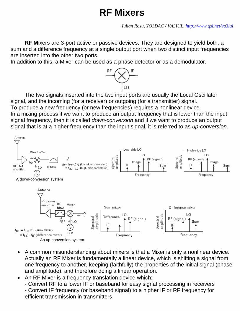
RF Mixers are 3-port active or passive devices. They are designed to yield both, a sum and a difference frequency at a single output port when two distinct input frequencies are inserted into the other two ports. In addition to this, a Mixer can be used as a phase detector or as a demodulator.
The two signals inserted into the two input ports are usually the Local Oscillator
signal, and the incoming (for a receiver) or outgoing (for a transmitter) signal. To produce a new frequency (or new frequencies) requires a nonlinear device. In a mixing process if we want to produce an output frequency that is lower than the input signal frequency, then it is called down-conversion and if we want to produce an output signal that is at a higher frequency than the input signal, it is referred to as up-conversion.
A down-conversion system
An up-conversion system
A common misunderstanding about mixers is that a Mixer is only a nonlinear device. Actually an RF Mixer is fundamentally a linear device, which is shifting a signal from one frequency to another, keeping (faithfully) the properties of the initial signal (phase and amplitude), and therefore doing a linear operation.
An RF Mixer is a frequency translation device which: - Convert RF to a lower IF or baseband for easy signal processing in receivers - Convert IF frequency (or baseband signal) to a higher IF or RF frequency for efficient transmission in transmitters.
From the moment that we use a nonlinear device to perform the mixing operation, Mixers have relatively high levels of intermodulation distortion, spurious responses, and other undesirable nonlinear phenomena.
In contrast to frequency multipliers and dividers, which also change signal frequency, mixers theoretically preserve the amplitude and phase without affecting modulation properties of the signals at its ports.
Mixers creative use of nonlinearity or time-variance phenomenon’s, which are usually harmful and unwanted for an RF system
RF Mixers generates frequencies not present at their input and used together with appropriate filtering they remove unwanted frequencies.
RF Mixers use two operation mechanisms: - Nonlinear transfer function, which use device nonlinearities creatively in a matter
that intermodulations creates the desired frequency and unwanted frequencies. - Switching or sampling is a time-varying process.
This method is preferred because has fewer spurs and can provide higher linearity. Important properties of an RF Mixer are:
Conversion Gain or Loss - lowers the noise impact of following stages.
Intercept Point (Linearity) - impacts receiver blocking and interferer performance.
Ports Isolation (LO-to-RF, LO-to-IF, RF-to-IF) - want to minimize interaction between the RF, IF, and LO ports.
Noise Figure - impacts receiver sensitivity.
High-order spurious response rejection.
Image Noise suppression – improves system noise figure.
Operating Frequency Range. 1. Conversion Gain or Loss of the RF Mixer is dependent by the type of the mixer (active or passive), is dependent by the load of the input RF circuit as well the output impedance at the IF port, and also is dependent by the level of the LO.
Conversion Gain or Loss is the ratio of the desired IF output (voltage or power) to the RF input signal value (voltage or power).
If the input impedance and the load impedance of the mixer are both equal to the source impedance, then the voltage conversion gain and the power conversion gain of the mixer will be the same in dB’s
The typical conversion gain of an Active Mixer is approximately +10dB, when the conversion loss of a typical Diode Mixer is approximately -6dB.
The Conversion Gain or Loss of the RF Mixer measured in dB is given by: Conversion[dB] = Output IF power delivered to the load[dBm] – RF input power[dBm] 2. Input Intercept Point (IIP3) is the RF input power at which the output power levels of the unwanted intermodulation products and the desired IF output would be equal. From RF System point of view, Mixer linearity is more critical than its Noise Figure.
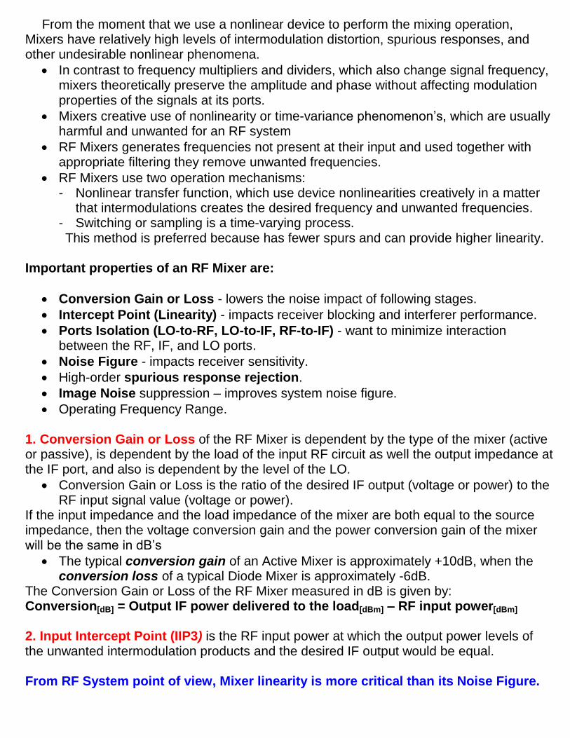
In a receiver, the most damaging distortion products are odd-order, since those are most likely fall within the same passband as the desired signal. The highest amplitude will be the lowest order, i.e, the 3rd order products. The most common figure of merit for intermodulation distortion (IMD) is Third Order Intercept (TOI).
The Third-Order Intercept point (TOI or IP3) in a Mixer is the fictional value defined by the extrapolated intersection of the primary IF response with the two-tone 3rd intermodulation IF product that results when two RF signals are applied to the RF port
In any application where IIP3 is very important, a large LO power is required.
The LO (Local Oscillator) provides switching of the signal input, interrupting or redirecting the signal current.
Both, Diode and FET Mixers can benefit from LO switching.
Silicon bipolar transistors (BJTs) do not switch well above Ft/10, thus degrading IIP3 and NF.
In a well designed passive Diode Mixer should get: IIP3[dB] ~ LO[dBm] + 9dB
Because the LO voltage is applied from the gate to the source-drain, and the signal flows from source to drain, there is an independence that allows FETs to have a higher IIP3 for a given LO drive than a Diode Mixer. The gate to channel impedance is very high, while the channel drain to source resistance is low.
In passive FET mixers, the gate input which is driven by the LO looks like a high-Q, capacitor. After tuning out this capacitance, the real LO power required to drive the mixer with a large voltage at frequency F is reduced by a factor of GMAX . Therefore, for FET mixers: IIP3[dBm] ~ LO[dBm] + 9dB + 20LOG(GMAX) (Where GMAX = Maximum available Gain at Frequency F) This shows why FETs with a high Fmax make better passive mixers than diodes.
Nonlinearity in RF Input Path is the same as in LNA nonlinearity case. As in case of the LNA this nonlinearity can be characterized with IIP3 and using a two-test to measure.
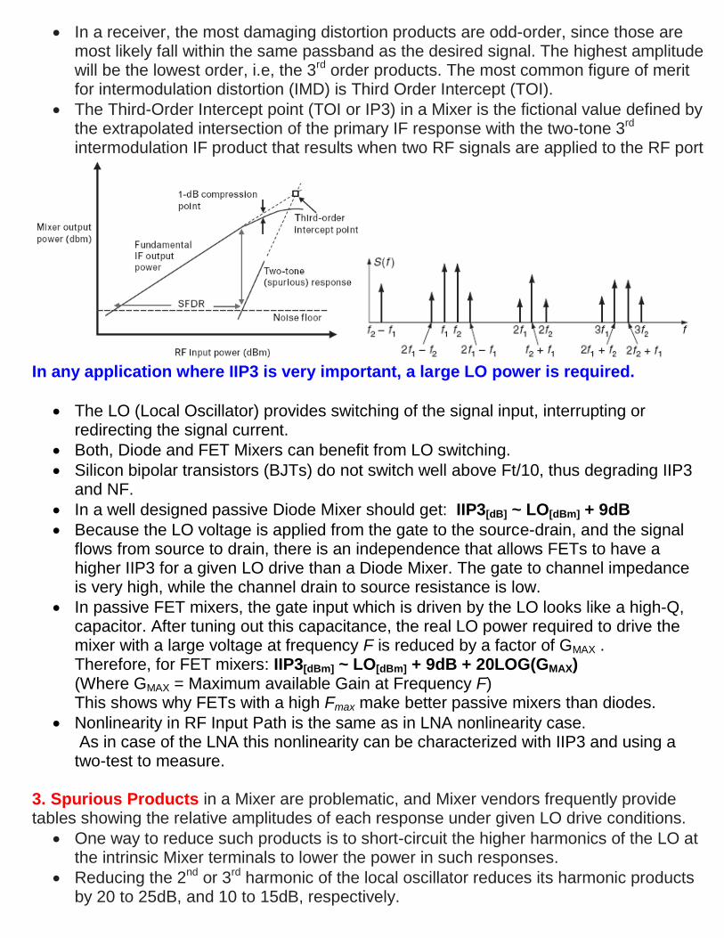
3. Spurious Products in a Mixer are problematic, and Mixer vendors frequently provide tables showing the relative amplitudes of each response under given LO drive conditions.
One way to reduce such products is to short-circuit the higher harmonics of the LO at the intrinsic Mixer terminals to lower the power in such responses.
Reducing the 2nd or 3rd harmonic of the local oscillator reduces its harmonic products by 20 to 25dB, and 10 to 15dB, respectively.
4. Isolation is the amount of local oscillator power that leaks into either the IF or the RF ports. There are multiple types of isolation: LO-to-RF, LO-to-IF and RF-to-IF isolation.
Self-Mixing of Reverse LO feed-through: - LO component in the RF input can pass back through the mixer and be modulated by
the LO signal, and a DC and 2fo components are created at the IF output. - This has no consequence for a heterodyne system, but can cause problems for
homodyne systems (i.e., zero IF)
LO to RF port isolation is by far the biggest short coming 5. Noise Figure is a measure of the noise added by the Mixer itself, noise as it gets converted to the IF output.
For a passive Mixer which has no gain and only loss, the Noise Figure is almost equal with the insertion loss.
In a mixer noise is replicated and translated by each harmonic of the LO that is referred to as Noise Folding.
In addition to the degradation in system Noise Figure introduced by the conversion loss of the Mixer, noise sources within the Mixer device itself further corrupt the Noise Figure.
For example, the effect of 1/f noise in MESFETs can be severe if the IF frequency is below the corner frequency of the flicker noise (normally less than 1 MHz), as this noise will add to the output.
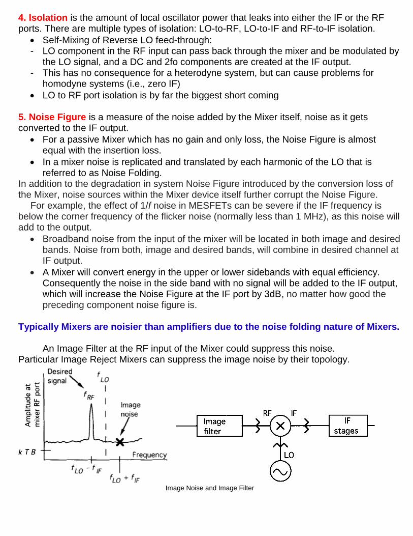
Broadband noise from the input of the mixer will be located in both image and desired bands. Noise from both, image and desired bands, will combine in desired channel at IF output.
A Mixer will convert energy in the upper or lower sidebands with equal efficiency. Consequently the noise in the side band with no signal will be added to the IF output, which will increase the Noise Figure at the IF port by 3dB, no matter how good the preceding component noise figure is.
Typically Mixers are noisier than amplifiers due to the noise folding nature of Mixers.
An Image Filter at the RF input of the Mixer could suppress this noise.
Particular Image Reject Mixers can suppress the image noise by their topology.
Image Noise and Image Filter
The wideband noise of the Local Oscillator is another parameter that can raise the IF noise level, degrading in this way the overall Noise Figure.
The wideband noise separated from the LO frequency by +/- fIF spacing, will mix to produce noise at IF frequency.
Any noise that is near a multiple of the LO frequency can also be mixed down to the IF, just like the noise at the RF. This noise conversion process is related, but not the same as, the LO-to-RF isolation.
Noise at frequencies of +/- fIF spacing from the LO harmonics also contributes to overall system Noise Figure.
Wideband LO noise is down-converted to IF with much higher conversion loss than the desired signal and image noise.
A Band Pass Filter between LO and the Mixer could help reducing the wideband LO noise.
In case of Mixers, the Noise Figure is defined for both the image and RF responses, and the output noise is generated by the input termination includes only the noise arising from the principal frequency transformation of the system.
When a Single Sideband Noise Figure at the RF input is to be determined, the output
noise arising from the input termination, at the image frequency is not included. Furthermore, it is impossible to measure directly the noise figure thus defined, because noiseless image terminations are difficult to obtain. The use of a filter to eliminate the image response (only to do accurate NF measurement) does not help because it changes the image-frequency embedding impedance, and hence changes the noise temperature. So, an alternate definition of Mixer SSB Noise Figure has found more common use.
When a noisy LO signal is applied to the Mixer, its noise components at the RF and
image frequencies are down converted and appear at the IF port, just as if they had been applied to the RF input. It is important to pick the IF frequency high enough so that noise at the RF and image frequencies are well separated from the LO and can be filtered effectively.
SSB NF assumes signal input from only one sideband, but noise inputs from both sidebands. Measuring SSB noise figure is relevant for super-heterodyne receiver architectures in which the image frequency is removed by filtering or cancellation. SSB NF is the ratio of SNR at the desired output frequency (IF) to the SNR at input frequency (RF) measured in a Single Side Band.
DSB NF includes both signal and noise inputs from both sidebands. A DSB NF is easier to measure; wideband excess noise is introduced at both the signal and image frequencies. It will be 3dB less than the SSB noise figure in most cases. For Direct Conversion Receivers (Zero IF), there is no image band (image cannot be filtered out from the signal), therefore noise from positive and negative frequencies combine, but the signals combine as well. DSB NF is the ratio of SNR at the output (IF) to the SNR at the input measured in both signal and image side bands (input signal spectrum resides on both sides of LO frequency, a common case in a homodyne or zero-IF systems).
6. Operating Frequency Range – Mixers are usually required from low frequencies up to tens of GHz. The operating frequency range is fundamental design characteristic that will in part determine the final selection of the mixer type. Mixers can be divided in classes, which all may be implemented as passive or active:
a) Single-device Mixer b) Single-Balanced Mixer c) Double-Balanced Mixer.
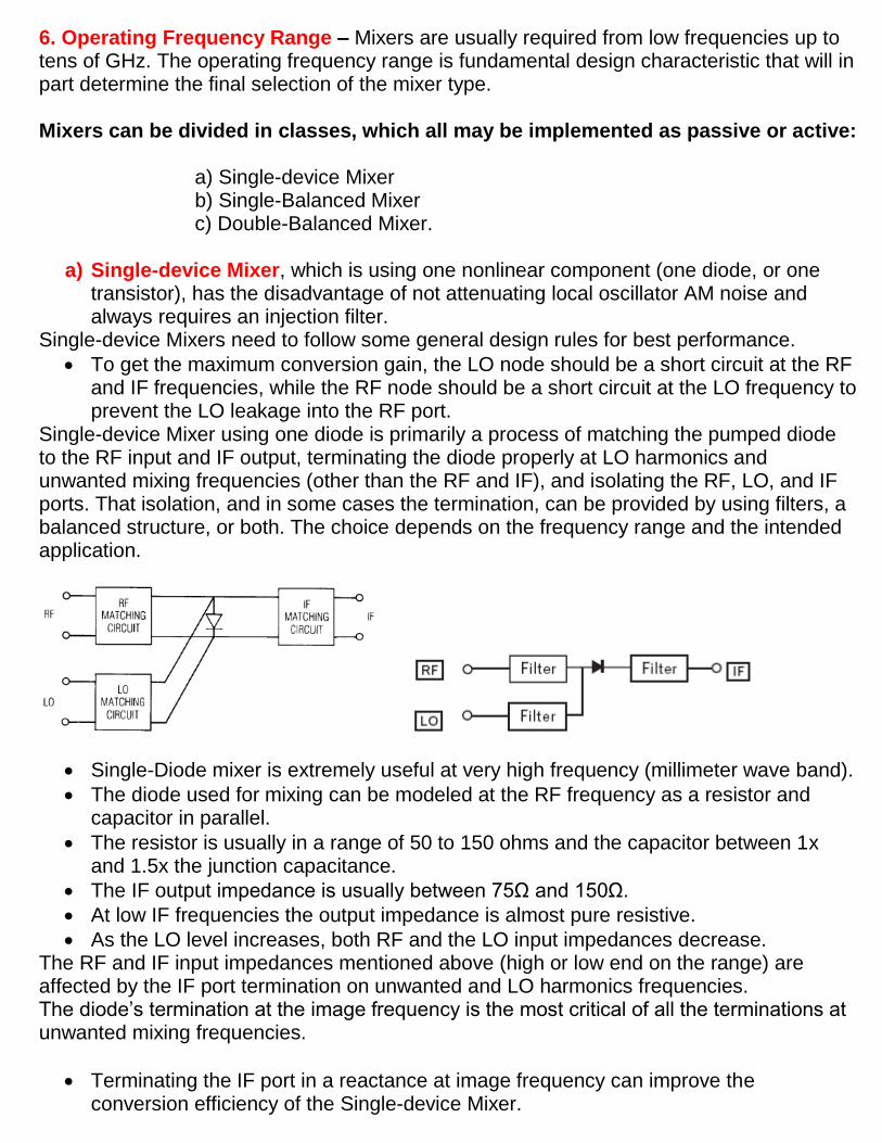
a) Single-device Mixer, which is using one nonlinear component (one diode, or one
transistor), has the disadvantage of not attenuating local oscillator AM noise and always requires an injection filter.
Single-device Mixers need to follow some general design rules for best performance.
To get the maximum conversion gain, the LO node should be a short circuit at the RF and IF frequencies, while the RF node should be a short circuit at the LO frequency to prevent the LO leakage into the RF port.
Single-device Mixer using one diode is primarily a process of matching the pumped diode to the RF input and IF output, terminating the diode properly at LO harmonics and unwanted mixing frequencies (other than the RF and IF), and isolating the RF, LO, and IF ports. That isolation, and in some cases the termination, can be provided by using filters, a balanced structure, or both. The choice depends on the frequency range and the intended application.
Single-Diode mixer is extremely useful at very high frequency (millimeter wave band).
The diode used for mixing can be modeled at the RF frequency as a resistor and capacitor in parallel.
The resistor is usually in a range of 50 to 150 ohms and the capacitor between 1x and 1.5x the junction capacitance.
The IF output impedance is usually between 75Ω and 150Ω.
At low IF frequencies the output impedance is almost pure resistive.
As the LO level increases, both RF and the LO input impedances decrease. The RF and IF input impedances mentioned above (high or low end on the range) are affected by the IF port termination on unwanted and LO harmonics frequencies. The diode’s termination at the image frequency is the most critical of all the terminations at unwanted mixing frequencies.
Terminating the IF port in a reactance at image frequency can improve the conversion efficiency of the Single-device Mixer.
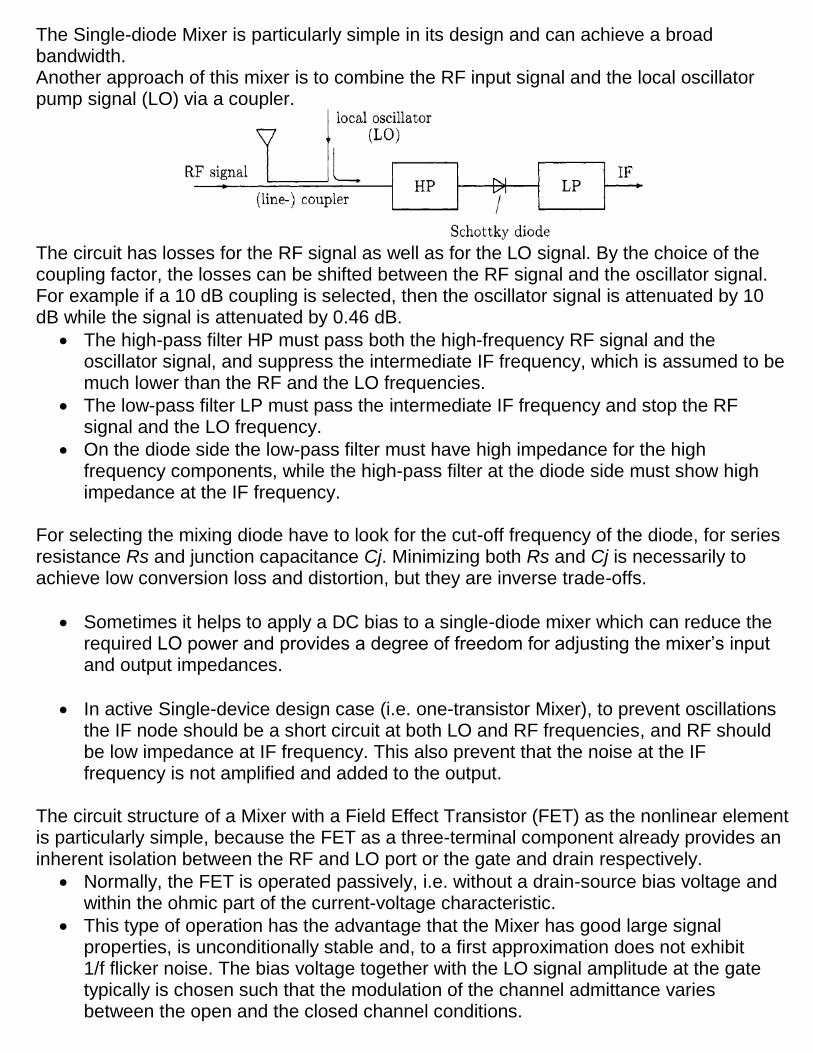
The Single-diode Mixer is particularly simple in its design and can achieve a broad bandwidth. Another approach of this mixer is to combine the RF input signal and the local oscillator pump signal (LO) via a coupler.
The circuit has losses for the RF signal as well as for the LO signal. By the choice of the coupling factor, the losses can be shifted between the RF signal and the oscillator signal. For example if a 10 dB coupling is selected, then the oscillator signal is attenuated by 10 dB while the signal is attenuated by 0.46 dB.
The high-pass filter HP must pass both the high-frequency RF signal and the oscillator signal, and suppress the intermediate IF frequency, which is assumed to be much lower than the RF and the LO frequencies.
The low-pass filter LP must pass the intermediate IF frequency and stop the RF signal and the LO frequency.
On the diode side the low-pass filter must have high impedance for the high frequency components, while the high-pass filter at the diode side must show high impedance at the IF frequency.
For selecting the mixing diode have to look for the cut-off frequency of the diode, for series resistance Rs and junction capacitance Cj. Minimizing both Rs and Cj is necessarily to achieve low conversion loss and distortion, but they are inverse trade-offs.
Sometimes it helps to apply a DC bias to a single-diode mixer which can reduce the required LO power and provides a degree of freedom for adjusting the mixer’s input and output impedances.
In active Single-device design case (i.e. one-transistor Mixer), to prevent oscillations the IF node should be a short circuit at both LO and RF frequencies, and RF should be low impedance at IF frequency. This also prevent that the noise at the IF frequency is not amplified and added to the output.
The circuit structure of a Mixer with a Field Effect Transistor (FET) as the nonlinear element is particularly simple, because the FET as a three-terminal component already provides an inherent isolation between the RF and LO port or the gate and drain respectively.
Normally, the FET is operated passively, i.e. without a drain-source bias voltage and within the ohmic part of the current-voltage characteristic.
This type of operation has the advantage that the Mixer has good large signal properties, is unconditionally stable and, to a first approximation does not exhibit 1/f flicker noise. The bias voltage together with the LO signal amplitude at the gate typically is chosen such that the modulation of the channel admittance varies between the open and the closed channel conditions.
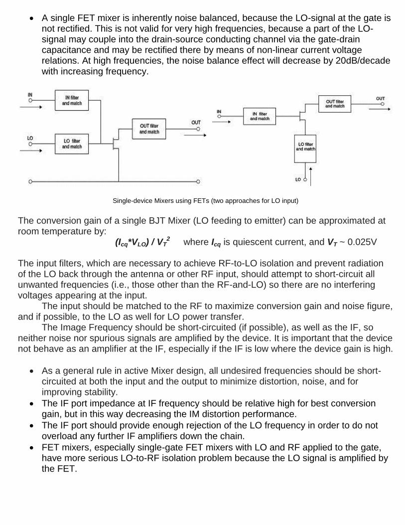
A single FET mixer is inherently noise balanced, because the LO-signal at the gate is not rectified. This is not valid for very high frequencies, because a part of the LO-signal may couple into the drain-source conducting channel via the gate-drain capacitance and may be rectified there by means of non-linear current voltage relations. At high frequencies, the noise balance effect will decrease by 20dB/decade with increasing frequency.
Single-device Mixers using FETs (two approaches for LO input)
The conversion gain of a single BJT Mixer (LO feeding to emitter) can be approximated at room temperature by:
(Icq*VLO) / VT2 where Icq is quiescent current, and VT ~ 0.025V
The input filters, which are necessary to achieve RF-to-LO isolation and prevent radiation of the LO back through the antenna or other RF input, should attempt to short-circuit all unwanted frequencies (i.e., those other than the RF-and-LO) so there are no interfering voltages appearing at the input.
The input should be matched to the RF to maximize conversion gain and noise figure, and if possible, to the LO as well for LO power transfer.
The Image Frequency should be short-circuited (if possible), as well as the IF, so neither noise nor spurious signals are amplified by the device. It is important that the device not behave as an amplifier at the IF, especially if the IF is low where the device gain is high.
As a general rule in active Mixer design, all undesired frequencies should be short-circuited at both the input and the output to minimize distortion, noise, and for improving stability.
The IF port impedance at IF frequency should be relative high for best conversion gain, but in this way decreasing the IM distortion performance.
The IF port should provide enough rejection of the LO frequency in order to do not overload any further IF amplifiers down the chain.
FET mixers, especially single-gate FET mixers with LO and RF applied to the gate, have more serious LO-to-RF isolation problem because the LO signal is amplified by the FET.
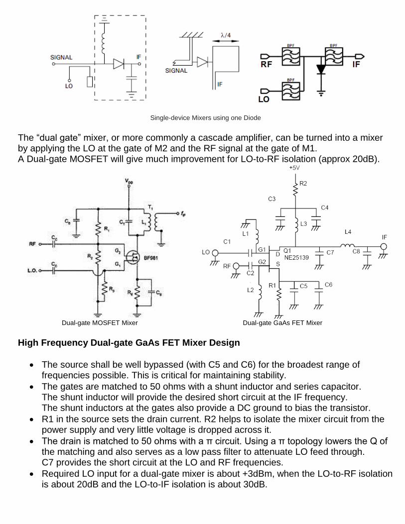
Single-device Mixers using one Diode
The “dual gate” mixer, or more commonly a cascade amplifier, can be turned into a mixer by applying the LO at the gate of M2 and the RF signal at the gate of M1. A Dual-gate MOSFET will give much improvement for LO-to-RF isolation (approx 20dB).
Dual-gate MOSFET Mixer Dual-gate GaAs FET Mixer
High Frequency Dual-gate GaAs FET Mixer Design
The source shall be well bypassed (with C5 and C6) for the broadest range of frequencies possible. This is critical for maintaining stability.
The gates are matched to 50 ohms with a shunt inductor and series capacitor. The shunt inductor will provide the desired short circuit at the IF frequency. The shunt inductors at the gates also provide a DC ground to bias the transistor.
R1 in the source sets the drain current. R2 helps to isolate the mixer circuit from the power supply and very little voltage is dropped across it.
The drain is matched to 50 ohms with a π circuit. Using a π topology lowers the Q of the matching and also serves as a low pass filter to attenuate LO feed through. C7 provides the short circuit at the LO and RF frequencies.
Required LO input for a dual-gate mixer is about +3dBm, when the LO-to-RF isolation is about 20dB and the LO-to-IF isolation is about 30dB.
Conjugate impedance matching of all ports, and adjusting the proper drain current, gives the best Noise Figure and gain. Meantime, higher IP3 can be achieved by increasing the drain current; however, an increase in Noise Figure will result. - As an example, tuning for best Noise Figure can get: NF=5dB, Gain=12dB,
P1dB=-1dBm, IP3=+7dBm. - And the same, tuning for best IP3 can get: NF=11dB, Gain=11dB, P1dB=+4dBm,
IP3=+14dBm The input and output impedances of the dual-gate FET are very high. This makes the matching to be narrow band. In narrow band super-heterodyne receivers (where the RF bandwidth is less than 50 MHz) this can be advantageous because the mixer has low conversion gain at image frequency. So, the image rejection performance of a receiver (including image noise rejection) could be improved by as much as 16dB without adding any cost to the preselector filter (image filter). Balanced Mixers are grossly divided into two classes, called Single-Balanced Mixers (SBM) and Double-Balanced Mixers (DBM).
b) Single-Balanced Mixer goes some way to solve the problems of single-device mixer by providing isolation between LO and RF inputs. It use two devices, and are usually realized as two single-device mixers connected via a 180-degree or 90-degree hybrid.
Double balanced mixers usually consist of four un-tuned devices interconnected by multiple hybrids, transformers or baluns. The advantages of balanced mixers over single-device mixers are:
- Rejection of spurious responses and intermodulation products. - Better LO-to-RF, RF-to-IF, and LO-to-IF isolation. - Rejection of AM noise in the LO
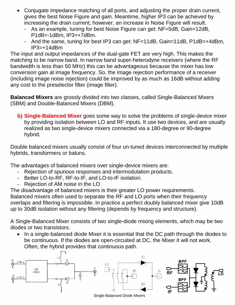
The disadvantage of balanced mixers is their greater LO power requirements. Balanced mixers often used to separate the RF and LO ports when their frequency overlaps and filtering is impossible. In practice a perfect doubly balanced mixer give 10dB up to 30dB isolation without any filtering (depends by frequency and structure). A Single-Balanced Mixer consists of two single-diode mixing elements, which may be two diodes or two transistors.
In a single-balanced diode Mixer it is essential that the DC path through the diodes to be continuous. If the diodes are open-circuited at DC, the Mixer it will not work. Often, the hybrid provides that continuous path.
Single-Balanced Diode Mixers
In single-balanced using a quadrature hybrid, the LO power reflected from the individual mixers does not return to the LO port, but instead exits the RF port; similarly, reflected RF power exits the LO port. The LO-to-RF and RF-to-LO isolation is therefore equal to the input return loss of the individual mixers at the LO and RF frequencies, respectively; the port isolation of the quadrature hybrid mixer depends primarily on the input VSWRs of the two individual mixers, not on the isolation of the hybrid itself. Isolation of 10dB is typical.
If the RF port termination has a poor VSWR at the LO frequency, the circuit’s balance can be upset and the LO pumping of the individual mixers becomes unequal. The same, a poor LO port termination at the RF frequency can upset RF balance. The even LO harmonics rejection depends by which port is used for LO input (Sigma or Delta). Whatever input is used for LO, the mixer reject the even LO harmonics that mix with the even RF harmonics.
To reduce the overall Noise Figure of the Mixer the two diodes shall be well matched. Diodes can be matched on RF characteristics (conversion loss, IF impedance and VSWR), but are more easily matched on DC parameters (junction capacitance, series resistance and forward voltage) that can be measured readily for all diode outlines, including beam lead types.
For practical mixers the single-balancing effect is in the order of 20dB to 40dB. This is normally sufficient to eliminate the influence of the LO signal amplitude noise to the noise figure of the mixer. Then, the noise figure of the mixer can be determined by its intrinsic noise.
c) Double-Balanced Mixer have higher conversion loss (or lower gain) than single-
balanced Mixer and lower limit in maximum frequency, but has broader bandwidth.
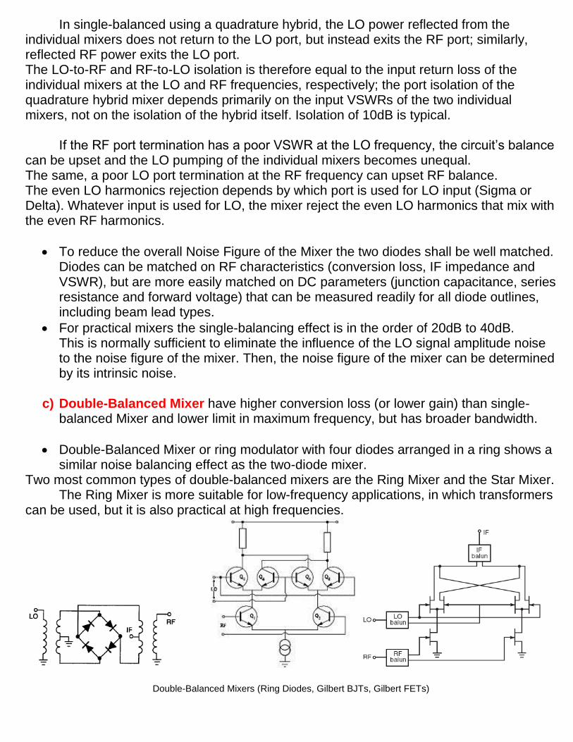
Double-Balanced Mixer or ring modulator with four diodes arranged in a ring shows a similar noise balancing effect as the two-diode mixer.
Two most common types of double-balanced mixers are the Ring Mixer and the Star Mixer. The Ring Mixer is more suitable for low-frequency applications, in which transformers
can be used, but it is also practical at high frequencies.
Double-Balanced Mixers (Ring Diodes, Gilbert BJTs, Gilbert FETs)
Double-Balanced Mixers can be described by treating its non-linear components (diode or transistors) as switches, which are turned ON and OFF by the LO signal power.
Both, diode and FET mixers can benefit from LO switching, when silicon bipolar transistors (BJT) do not switch well above Ft/10, thus degrading IIP3 and Noise Figure at higher frequencies.
The advantages of a double-balanced mixer over a single balanced mixer are: increased linearity, improved suppression of spurious products (all even order products of the LO and/or the RF are suppressed) and provides inherent good isolation between all ports.
Their ports are interchangeable, and require easy filtering.
The disadvantage is that they require a relative higher level LO drive, and they require two transformer baluns (BALance to UNbalance).
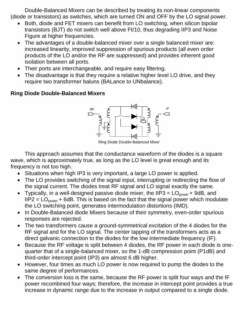
Ring Diode Double-Balanced Mixers
Ring Diode Double-Balanced Mixer
This approach assumes that the conductance waveform of the diodes is a square
wave, which is approximately true, as long as the LO level is great enough and its frequency is not too high.
Situations when high IP3 is very important, a large LO power is applied.
The LO provides switching of the signal input, interrupting or redirecting the flow of the signal current. The diodes treat RF signal and LO signal exactly the same.
Typically, in a well-designed passive diode mixer, the IIP3 = LOpower + 9dB, and IIP2 = LOpower + 6dB. This is based on the fact that the signal power which modulate the LO switching point, generates intermodulation distortions (IMD).
In Double-Balanced diode Mixers because of their symmetry, even-order spurious responses are rejected.
The two transformers cause a ground-symmetrical excitation of the 4 diodes for the RF signal and for the LO signal. The center tapping of the transformers acts as a direct galvanic connection to the diodes for the low intermediate frequency (IF).
Because the RF voltage is split between 4 diodes, the RF power in each diode is one-quarter that of a single-balanced mixer, so the 1-dB compression point (P1dB) and third-order intercept point (IP3) are almost 6 dB higher.
However, four times as much LO power is now required to pump the diodes to the same degree of performances.
The conversion loss is the same, because the RF power is split four ways and the IF power recombined four ways; therefore, the increase in intercept point provides a true increase in dynamic range due to the increase in output compared to a single diode.
The performance of double-balanced diode mixer is dependent on a variety of factors as: operating frequency, LO power, impedance matching, and temperature.
In practice the IIP3 of a double-balanced diode mixer is about LOpower + 6dB. For LOpower greater than +10dBm, the influence of the LOpower is less significant for improving IIP3. If the LO power is greater than +10dBm, the increase in intercept point (IIP3) does not rise as fast as the rise of the LO power, because the ON diodes begin to limit the LO voltage across the OFF diodes, which are in parallel. To each diode, the RF current is indistinguishable from the LO current, and the total RF swing is therefore limited in the OFF condition. This can be improved by using two or more diodes in series in place of the single diodes shown.
The Noise Figure of a double-balanced diode mixer is about 5.5dB.
The conversion loss of a double balanced diode mixer is about 6dB.
Proper matching of the IF output is essential to gain optimum performance from double-balanced diode mixer. Failure to ensure proper matching will result in higher conversion losses and generation of unwanted harmonics.
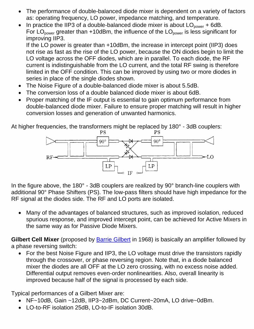
At higher frequencies, the transformers might be replaced by 180° - 3dB couplers:
In the figure above, the 180° - 3dB couplers are realized by 90° branch-line couplers with additional 90° Phase Shifters (PS). The low-pass filters should have high impedance for the RF signal at the diodes side. The RF and LO ports are isolated.
Many of the advantages of balanced structures, such as improved isolation, reduced spurious response, and improved intercept point, can be achieved for Active Mixers in the same way as for Passive Diode Mixers.
Gilbert Cell Mixer (proposed by Barrie Gilbert in 1968) is basically an amplifier followed by a phase reversing switch:
For the best Noise Figure and IIP3, the LO voltage must drive the transistors rapidly through the crossover, or phase reversing region. Note that, in a diode balanced mixer the diodes are all OFF at the LO zero crossing, with no excess noise added. Differential output removes even-order nonlinearities. Also, overall linearity is improved because half of the signal is processed by each side.
Typical performances of a Gilbert Mixer are:
NF~10dB, Gain ~12dB, IIP3~2dBm, DC Current~20mA, LO drive~0dBm.
LO-to-RF isolation 25dB, LO-to-IF isolation 30dB.
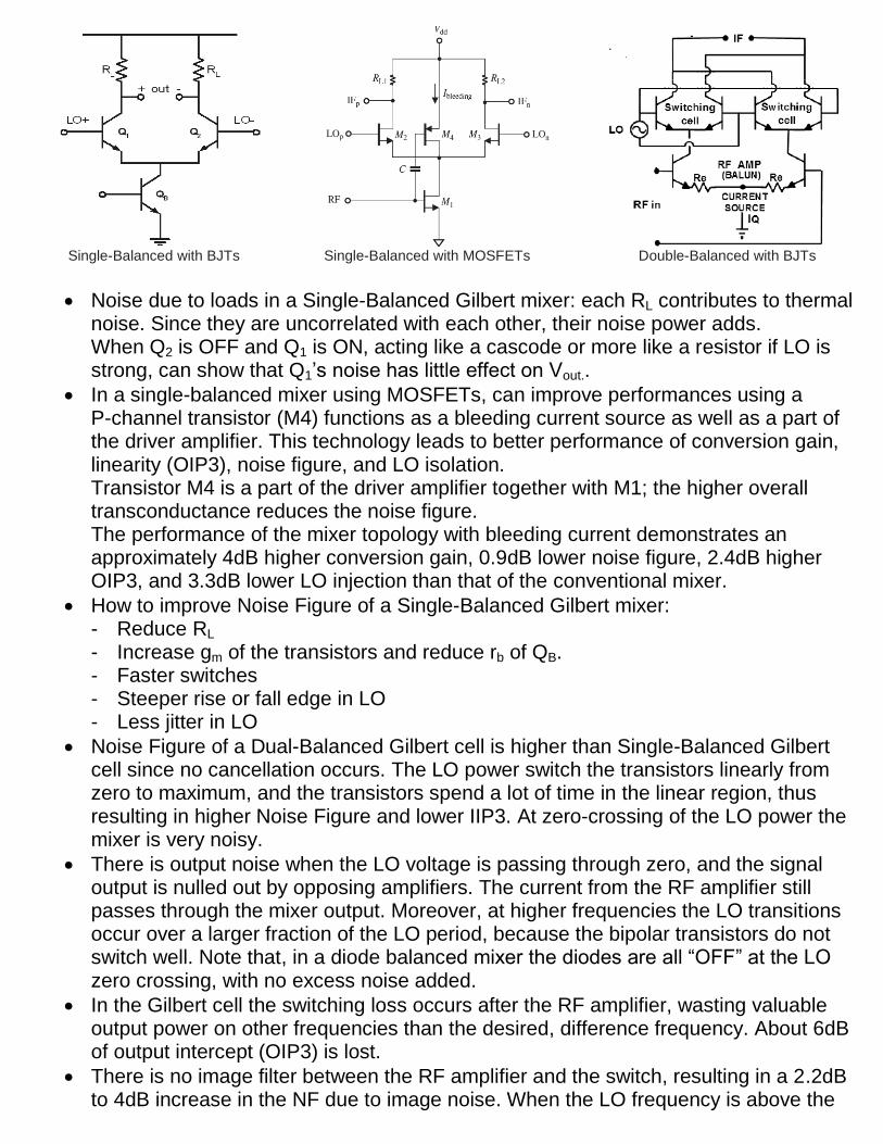
Single-Balanced with BJTs Single-Balanced with MOSFETs Double-Balanced with BJTs
Noise due to loads in a Single-Balanced Gilbert mixer: each RL contributes to thermal noise. Since they are uncorrelated with each other, their noise power adds. When Q2 is OFF and Q1 is ON, acting like a cascode or more like a resistor if LO is strong, can show that Q1’s noise has little effect on Vout..
In a single-balanced mixer using MOSFETs, can improve performances using a P-channel transistor (M4) functions as a bleeding current source as well as a part of the driver amplifier. This technology leads to better performance of conversion gain, linearity (OIP3), noise figure, and LO isolation. Transistor M4 is a part of the driver amplifier together with M1; the higher overall transconductance reduces the noise figure. The performance of the mixer topology with bleeding current demonstrates an approximately 4dB higher conversion gain, 0.9dB lower noise figure, 2.4dB higher OIP3, and 3.3dB lower LO injection than that of the conventional mixer.
How to improve Noise Figure of a Single-Balanced Gilbert mixer: - Reduce RL - Increase gm of the transistors and reduce rb of QB. - Faster switches - Steeper rise or fall edge in LO - Less jitter in LO
Noise Figure of a Dual-Balanced Gilbert cell is higher than Single-Balanced Gilbert cell since no cancellation occurs. The LO power switch the transistors linearly from zero to maximum, and the transistors spend a lot of time in the linear region, thus resulting in higher Noise Figure and lower IIP3. At zero-crossing of the LO power the mixer is very noisy.
There is output noise when the LO voltage is passing through zero, and the signal output is nulled out by opposing amplifiers. The current from the RF amplifier still passes through the mixer output. Moreover, at higher frequencies the LO transitions occur over a larger fraction of the LO period, because the bipolar transistors do not switch well. Note that, in a diode balanced mixer the diodes are all “OFF” at the LO zero crossing, with no excess noise added.
In the Gilbert cell the switching loss occurs after the RF amplifier, wasting valuable output power on other frequencies than the desired, difference frequency. About 6dB of output intercept (OIP3) is lost.
There is no image filter between the RF amplifier and the switch, resulting in a 2.2dB to 4dB increase in the NF due to image noise. When the LO frequency is above the
signal frequency, more noise is added to the mixer output from the image frequency converted to the output, than from the signal frequency. In that case, for a 10% difference between LO and signal frequencies, the image noise adds 4dB to the mixer noise figure.
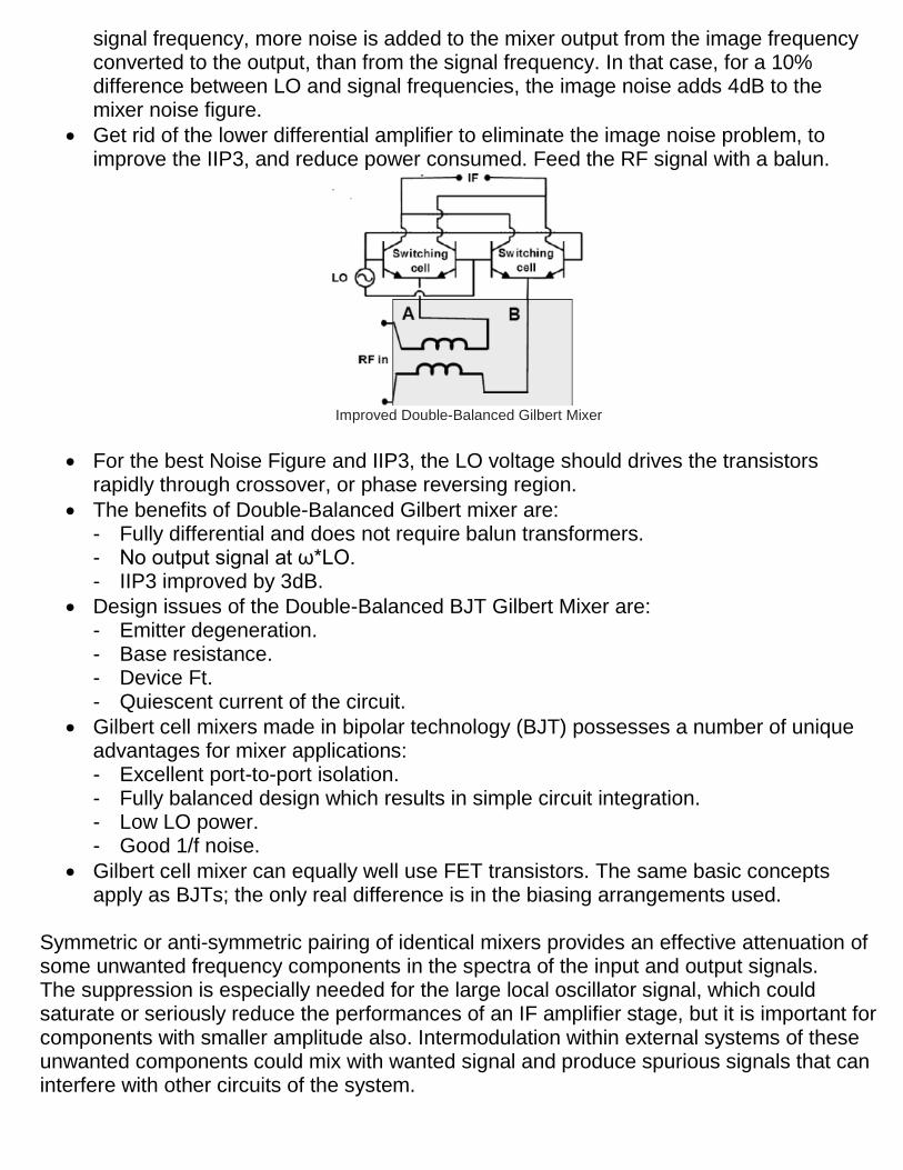
Get rid of the lower differential amplifier to eliminate the image noise problem, to improve the IIP3, and reduce power consumed. Feed the RF signal with a balun.
Improved Double-Balanced Gilbert Mixer
For the best Noise Figure and IIP3, the LO voltage should drives the transistors rapidly through crossover, or phase reversing region.
The benefits of Double-Balanced Gilbert mixer are: - Fully differential and does not require balun transformers. - No output signal at ω*LO. - IIP3 improved by 3dB.
Design issues of the Double-Balanced BJT Gilbert Mixer are: - Emitter degeneration. - Base resistance. - Device Ft. - Quiescent current of the circuit.
Gilbert cell mixers made in bipolar technology (BJT) possesses a number of unique advantages for mixer applications: - Excellent port-to-port isolation. - Fully balanced design which results in simple circuit integration. - Low LO power. - Good 1/f noise.
Gilbert cell mixer can equally well use FET transistors. The same basic concepts apply as BJTs; the only real difference is in the biasing arrangements used.
Symmetric or anti-symmetric pairing of identical mixers provides an effective attenuation of some unwanted frequency components in the spectra of the input and output signals. The suppression is especially needed for the large local oscillator signal, which could saturate or seriously reduce the performances of an IF amplifier stage, but it is important for components with smaller amplitude also. Intermodulation within external systems of these unwanted components could mix with wanted signal and produce spurious signals that can interfere with other circuits of the system.
Double-Balanced FET Mixers can be designed for both, passive and active use.
Active FET Mixers based on Gilbert Cell architecture with biased semiconductor devices, can work with low LO levels and often provide conversion gain, but with decreased linearity compared to passive mixers.
Passive FET Mixers, usually based on FET quads (ring connection), provide good linearity but require high LO levels and exhibit high conversion loss.
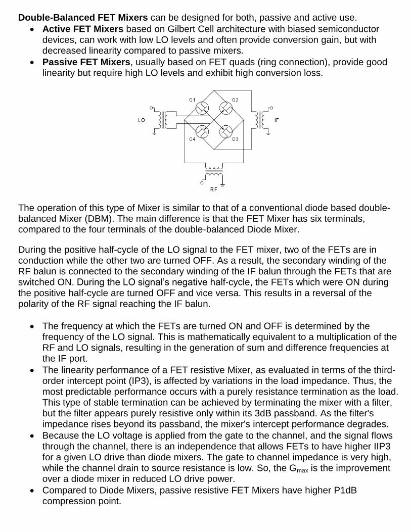
The operation of this type of Mixer is similar to that of a conventional diode based double-balanced Mixer (DBM). The main difference is that the FET Mixer has six terminals, compared to the four terminals of the double-balanced Diode Mixer.
During the positive half-cycle of the LO signal to the FET mixer, two of the FETs are in conduction while the other two are turned OFF. As a result, the secondary winding of the RF balun is connected to the secondary winding of the IF balun through the FETs that are switched ON. During the LO signal’s negative half-cycle, the FETs which were ON during the positive half-cycle are turned OFF and vice versa. This results in a reversal of the polarity of the RF signal reaching the IF balun.
The frequency at which the FETs are turned ON and OFF is determined by the frequency of the LO signal. This is mathematically equivalent to a multiplication of the RF and LO signals, resulting in the generation of sum and difference frequencies at the IF port.
The linearity performance of a FET resistive Mixer, as evaluated in terms of the third-order intercept point (IP3), is affected by variations in the load impedance. Thus, the most predictable performance occurs with a purely resistance termination as the load. This type of stable termination can be achieved by terminating the mixer with a filter, but the filter appears purely resistive only within its 3dB passband. As the filter's impedance rises beyond its passband, the mixer's intercept performance degrades.
Because the LO voltage is applied from the gate to the channel, and the signal flows through the channel, there is an independence that allows FETs to have higher IIP3 for a given LO drive than diode mixers. The gate to channel impedance is very high, while the channel drain to source resistance is low. So, the Gmax is the improvement over a diode mixer in reduced LO drive power.
Compared to Diode Mixers, passive resistive FET Mixers have higher P1dB compression point.
The P1dB compression point of a Diode Mixer is generally 4dB to 6dB lower than the power level of the LO signal, whereas the P1dB compression point of a passive FET Mixer is typically 3dB higher than the power level of the LO signal.
A good rule of thumb is that the passive dual-balanced Mixer (regardless, with diodes or with FETs) should be correctly terminated from the lowest frequency in use, to at least five times the highest frequency in use. A good solution is to use at the output of the mixer (IF) a Diplexer, which provides the correct termination impedance over a wide frequency range and also provides a degree of frequency selectivity at the IF.
In a Quad-FET passive Mixer, the IP3 is mainly a function of the switch transition time.
The transition time is mainly a function of the LO voltage, and in the case of a resonant drive is also function of the Q of the resonant circuit. For a given LO power, the higher the Q, the higher the IP3.
A quad-FET passive mixer (cold operation) has the important advantage, as has been mentioned in the single-FET passive mixer, that 1/f flicker noise is practically not induced.
JFET Mixers
The Junction-FET (JFET) active mixers offer potential good performance. Conversion Gain and Intermodulation Distortion (IMD) characteristics are superior to typical passive mixers, similar to that of high-level diode mixers.
In an active JFET mixer, the devices are biased for gain, but at the expense of intercept-point (IP3) performance.
Passive mixers require higher LO power levels, but provide better third-order intercept (IP3) performance.
JFETs have an inherent square-law response which reduces third-order IMD.
Like passive mixers, active JFET mixers have a high burn-out level. The main disadvantage of JFET mixers is that they need physically-matched transformers, and also they require relative high-level of local oscillator drive.
In active JFET mixers the optimum power gain and noise do not occur at operating point. The bias currents, local oscillator drive level and matching transformers must be properly selected to ensure that the FETs operate in the square-law region and that distortion is minimized.
The lowest achievable Noise Figure of an active JFET mixer is about 6dB.
For optimum performance of double-balanced JFET mixer, the transistors should be perfectly matched, which is relative difficult due characteristics between batches. Today there are available Quad-FETs in single package, specifically designed for mixer applications.
For Single-Balanced JFET mixers, the requirement for matched components is less stringent, allowing the use of transistors matched to within 10%.
Quad MOSFET Mixers
If there is a need for very high-level performance, than the JFETs can be substituted for either monolithic DMOS-FET quads, or a combination of RF Power MOSFETs.
Double-balanced MOSFET mixers may operate the transistors as switches with no drain voltage applied resulting in an insertion loss of about -6dB. Alternatively, drain voltage supplied to the MOSFET may be used to give a mixer gain about +15dB.
The LO waveform applied to this kind of mixer is of great importance. To achieve a high intercept point, the LO drive must approach an ideal square wave with a 50% duty-cycle.
One advantage of MOSFET is that the gate drive voltages are roughly the same for all MOSFET types. This means, the local oscillator power needed for a very high-level MOSFET mixer is less than the power required for an equivalent diode mixer.
MOSFET mixers suffer from the same problem as JFET mixers in terms of using transformers and high-part surrounding circuits, which use of large area circuit board.
Such kind of MOSFET mixers would be found in high performance HF receivers, in a frequency range from 1MHz to 50MHz.
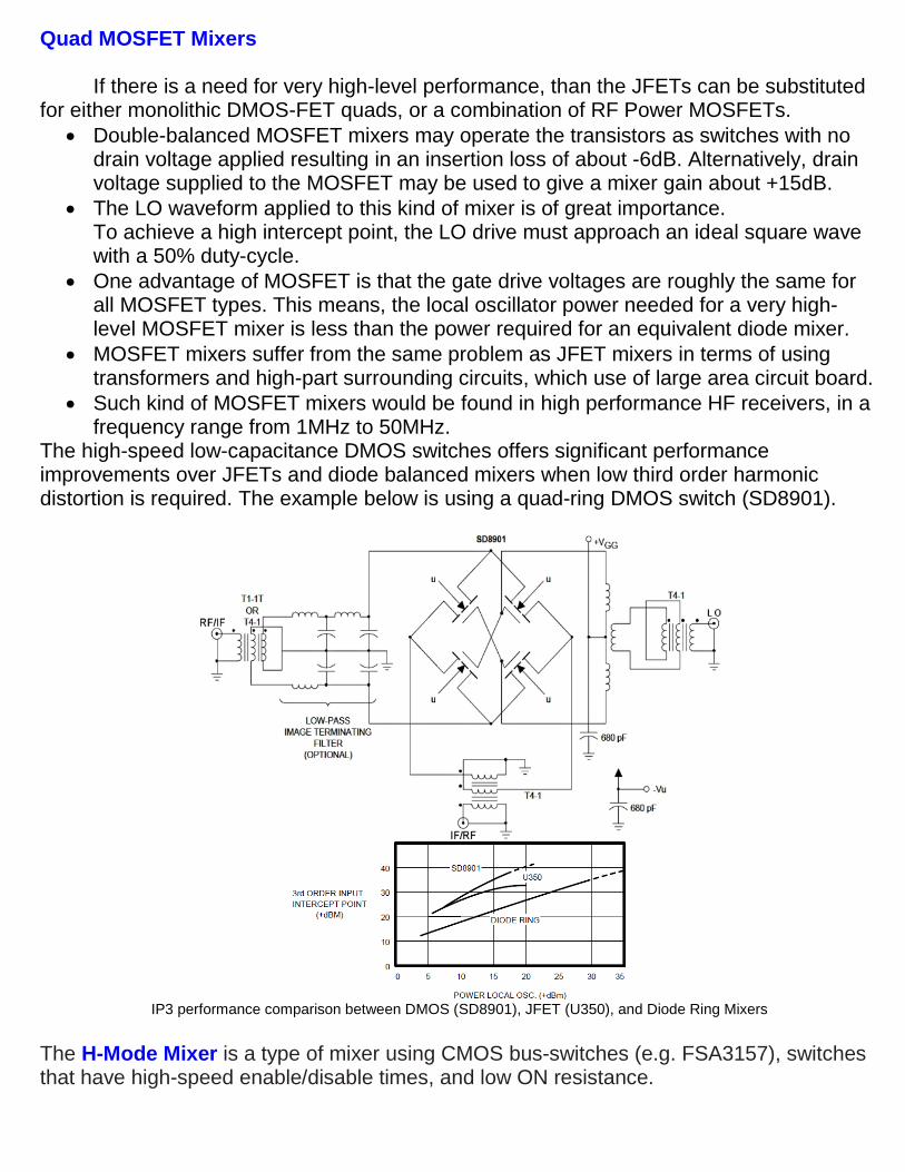
The high-speed low-capacitance DMOS switches offers significant performance improvements over JFETs and diode balanced mixers when low third order harmonic distortion is required. The example below is using a quad-ring DMOS switch (SD8901).
IP3 performance comparison between DMOS (SD8901), JFET (U350), and Diode Ring Mixers
The H-Mode Mixer is a type of mixer using CMOS bus-switches (e.g. FSA3157), switches that have high-speed enable/disable times, and low ON resistance.
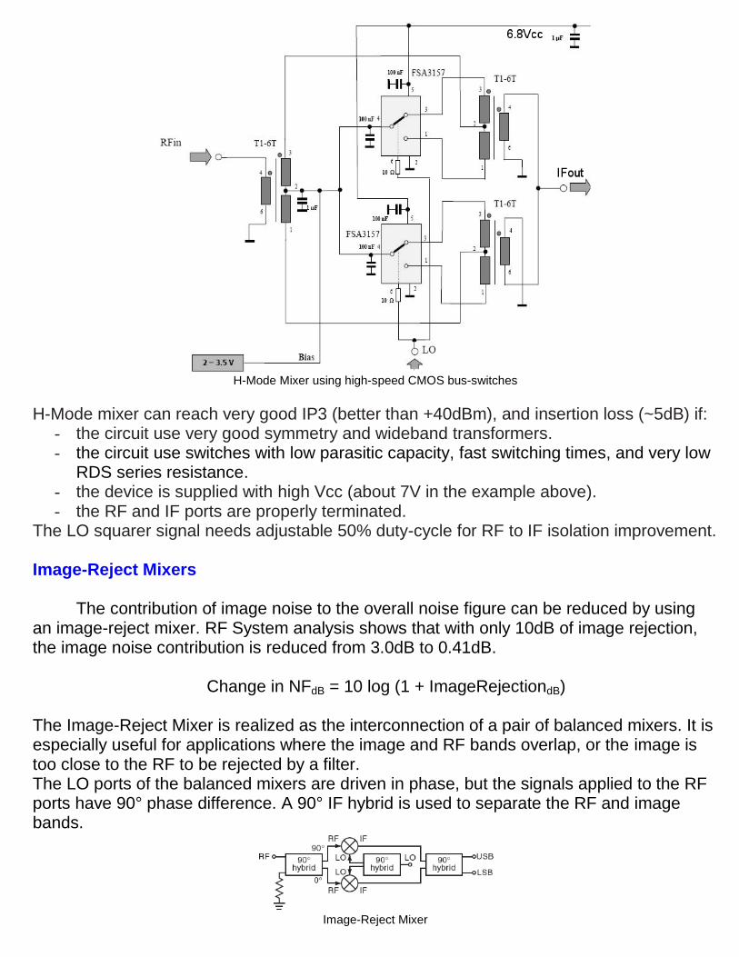
H-Mode Mixer using high-speed CMOS bus-switches
H-Mode mixer can reach very good IP3 (better than +40dBm), and insertion loss (~5dB) if: - the circuit use very good symmetry and wideband transformers. - the circuit use switches with low parasitic capacity, fast switching times, and very low
RDS series resistance. - the device is supplied with high Vcc (about 7V in the example above). - the RF and IF ports are properly terminated.
The LO squarer signal needs adjustable 50% duty-cycle for RF to IF isolation improvement. Image-Reject Mixers
The contribution of image noise to the overall noise figure can be reduced by using an image-reject mixer. RF System analysis shows that with only 10dB of image rejection, the image noise contribution is reduced from 3.0dB to 0.41dB.
Change in NFdB = 10 log (1 + ImageRejectiondB)
The Image-Reject Mixer is realized as the interconnection of a pair of balanced mixers. It is especially useful for applications where the image and RF bands overlap, or the image is too close to the RF to be rejected by a filter. The LO ports of the balanced mixers are driven in phase, but the signals applied to the RF ports have 90° phase difference. A 90° IF hybrid is used to separate the RF and image bands.
Image-Reject Mixer
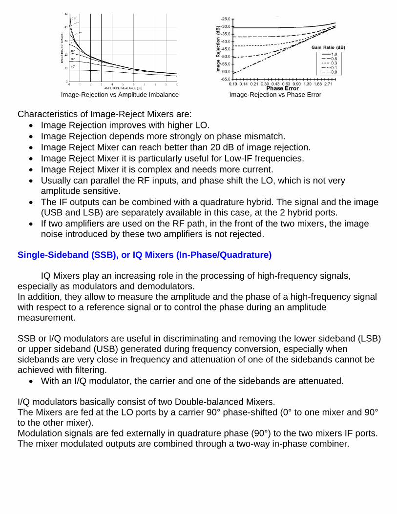
Image-Rejection vs Amplitude Imbalance Image-Rejection vs Phase Error
Characteristics of Image-Reject Mixers are:
Image Rejection improves with higher LO.
Image Rejection depends more strongly on phase mismatch.
Image Reject Mixer can reach better than 20 dB of image rejection.
Image Reject Mixer it is particularly useful for Low-IF frequencies.
Image Reject Mixer it is complex and needs more current.
Usually can parallel the RF inputs, and phase shift the LO, which is not very amplitude sensitive.
The IF outputs can be combined with a quadrature hybrid. The signal and the image (USB and LSB) are separately available in this case, at the 2 hybrid ports.
If two amplifiers are used on the RF path, in the front of the two mixers, the image noise introduced by these two amplifiers is not rejected.
Single-Sideband (SSB), or IQ Mixers (In-Phase/Quadrature)
IQ Mixers play an increasing role in the processing of high-frequency signals, especially as modulators and demodulators. In addition, they allow to measure the amplitude and the phase of a high-frequency signal with respect to a reference signal or to control the phase during an amplitude measurement. SSB or I/Q modulators are useful in discriminating and removing the lower sideband (LSB) or upper sideband (USB) generated during frequency conversion, especially when sidebands are very close in frequency and attenuation of one of the sidebands cannot be achieved with filtering.
With an I/Q modulator, the carrier and one of the sidebands are attenuated. I/Q modulators basically consist of two Double-balanced Mixers. The Mixers are fed at the LO ports by a carrier 90° phase-shifted (0° to one mixer and 90° to the other mixer). Modulation signals are fed externally in quadrature phase (90°) to the two mixers IF ports. The mixer modulated outputs are combined through a two-way in-phase combiner.
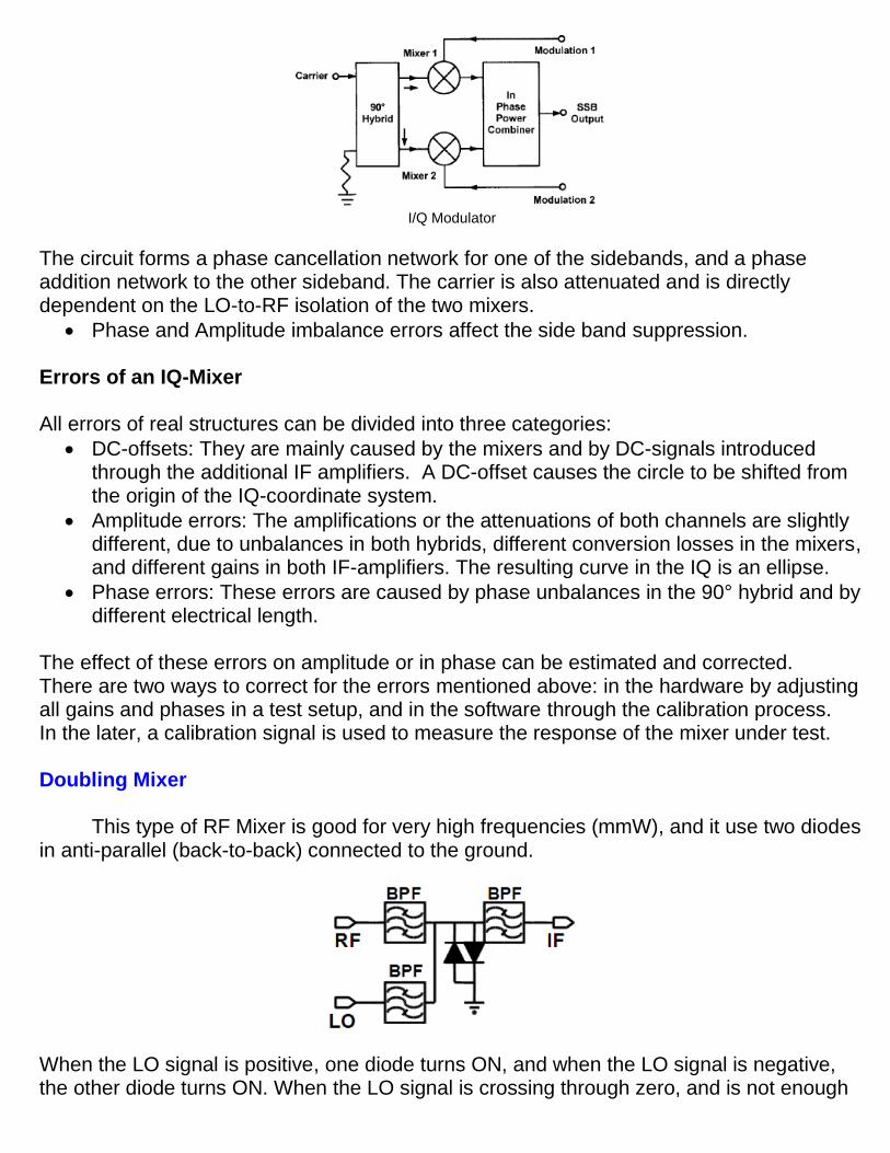
I/Q Modulator
The circuit forms a phase cancellation network for one of the sidebands, and a phase addition network to the other sideband. The carrier is also attenuated and is directly dependent on the LO-to-RF isolation of the two mixers.
Phase and Amplitude imbalance errors affect the side band suppression. Errors of an IQ-Mixer All errors of real structures can be divided into three categories:
DC-offsets: They are mainly caused by the mixers and by DC-signals introduced through the additional IF amplifiers. A DC-offset causes the circle to be shifted from the origin of the IQ-coordinate system.
Amplitude errors: The amplifications or the attenuations of both channels are slightly different, due to unbalances in both hybrids, different conversion losses in the mixers, and different gains in both IF-amplifiers. The resulting curve in the IQ is an ellipse.
Phase errors: These errors are caused by phase unbalances in the 90° hybrid and by different electrical length.
The effect of these errors on amplitude or in phase can be estimated and corrected. There are two ways to correct for the errors mentioned above: in the hardware by adjusting all gains and phases in a test setup, and in the software through the calibration process. In the later, a calibration signal is used to measure the response of the mixer under test. Doubling Mixer
This type of RF Mixer is good for very high frequencies (mmW), and it use two diodes
in anti-parallel (back-to-back) connected to the ground.
When the LO signal is positive, one diode turns ON, and when the LO signal is negative, the other diode turns ON. When the LO signal is crossing through zero, and is not enough
voltage to turn ON either diode, there will be an open circuit across the diodes at the frequency of the LO signal. The switching action of the LO apply a short-circuit to the ground at twice of the frequency of the LO. This mixer needs an LO signal with half of the necessary frequency, signal which is much easier to be generated at millimeter waves. For example, for a Direct Conversion Receiver with RF input signal at 70 GHz, the doubling-mixer needs a 35 GHz LO signal, instead of an LO signal of about 70 GHz. Sub-Harmonic Mixers
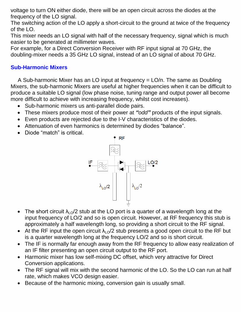
A Sub-harmonic Mixer has an LO input at frequency = LO/n. The same as Doubling
Mixers, the sub-harmonic Mixers are useful at higher frequencies when it can be difficult to produce a suitable LO signal (low phase noise, tuning range and output power all become more difficult to achieve with increasing frequency, whilst cost increases).
Sub-harmonic mixers us anti-parallel diode pairs.
These mixers produce most of their power at “odd” products of the input signals.
Even products are rejected due to the I-V characteristics of the diodes.
Attenuation of even harmonics is determined by diodes “balance”.
Diode “match” is critical.
The short circuit λLO/2 stub at the LO port is a quarter of a wavelength long at the
input frequency of LO/2 and so is open circuit. However, at RF frequency this stub is approximately a half wavelength long, so providing a short circuit to the RF signal.
At the RF input the open circuit λLO/2 stub presents a good open circuit to the RF but is a quarter wavelength long at the frequency LO/2 and so is short circuit.
The IF is normally far enough away from the RF frequency to allow easy realization of an IF filter presenting an open circuit output to the RF port.
Harmonic mixer has low self-mixing DC offset, which very attractive for Direct Conversion applications.
The RF signal will mix with the second harmonic of the LO. So the LO can run at half rate, which makes VCO design easier.
Because of the harmonic mixing, conversion gain is usually small.
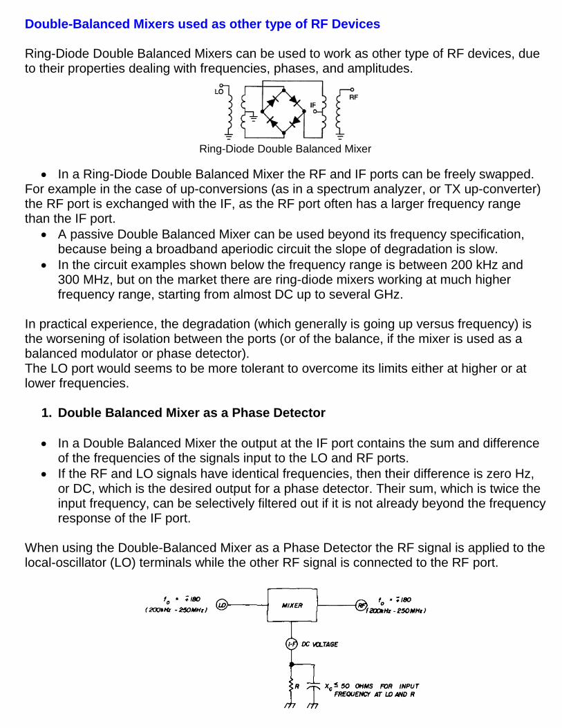
Double-Balanced Mixers used as other type of RF Devices Ring-Diode Double Balanced Mixers can be used to work as other type of RF devices, due to their properties dealing with frequencies, phases, and amplitudes.
Ring-Diode Double Balanced Mixer
In a Ring-Diode Double Balanced Mixer the RF and IF ports can be freely swapped. For example in the case of up-conversions (as in a spectrum analyzer, or TX up-converter) the RF port is exchanged with the IF, as the RF port often has a larger frequency range than the IF port.
A passive Double Balanced Mixer can be used beyond its frequency specification, because being a broadband aperiodic circuit the slope of degradation is slow.
In the circuit examples shown below the frequency range is between 200 kHz and 300 MHz, but on the market there are ring-diode mixers working at much higher frequency range, starting from almost DC up to several GHz.
In practical experience, the degradation (which generally is going up versus frequency) is the worsening of isolation between the ports (or of the balance, if the mixer is used as a balanced modulator or phase detector). The LO port would seems to be more tolerant to overcome its limits either at higher or at lower frequencies.
1. Double Balanced Mixer as a Phase Detector
In a Double Balanced Mixer the output at the IF port contains the sum and difference of the frequencies of the signals input to the LO and RF ports.
If the RF and LO signals have identical frequencies, then their difference is zero Hz, or DC, which is the desired output for a phase detector. Their sum, which is twice the input frequency, can be selectively filtered out if it is not already beyond the frequency response of the IF port.
When using the Double-Balanced Mixer as a Phase Detector the RF signal is applied to the local-oscillator (LO) terminals while the other RF signal is connected to the RF port.
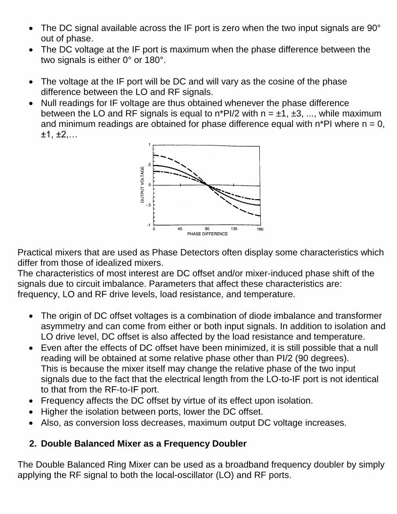
The DC signal available across the IF port is zero when the two input signals are 90° out of phase.
The DC voltage at the IF port is maximum when the phase difference between the two signals is either 0° or 180°.
The voltage at the IF port will be DC and will vary as the cosine of the phase difference between the LO and RF signals.
Null readings for IF voltage are thus obtained whenever the phase difference between the LO and RF signals is equal to n*PI/2 with n = ±1, ±3, ..., while maximum and minimum readings are obtained for phase difference equal with n*PI where n = 0, ±1, ±2,…
Practical mixers that are used as Phase Detectors often display some characteristics which differ from those of idealized mixers. The characteristics of most interest are DC offset and/or mixer-induced phase shift of the signals due to circuit imbalance. Parameters that affect these characteristics are: frequency, LO and RF drive levels, load resistance, and temperature.
The origin of DC offset voltages is a combination of diode imbalance and transformer asymmetry and can come from either or both input signals. In addition to isolation and LO drive level, DC offset is also affected by the load resistance and temperature.
Even after the effects of DC offset have been minimized, it is still possible that a null reading will be obtained at some relative phase other than PI/2 (90 degrees). This is because the mixer itself may change the relative phase of the two input signals due to the fact that the electrical length from the LO-to-IF port is not identical to that from the RF-to-IF port.
Frequency affects the DC offset by virtue of its effect upon isolation.
Higher the isolation between ports, lower the DC offset.
Also, as conversion loss decreases, maximum output DC voltage increases.
2. Double Balanced Mixer as a Frequency Doubler The Double Balanced Ring Mixer can be used as a broadband frequency doubler by simply applying the RF signal to both the local-oscillator (LO) and RF ports.
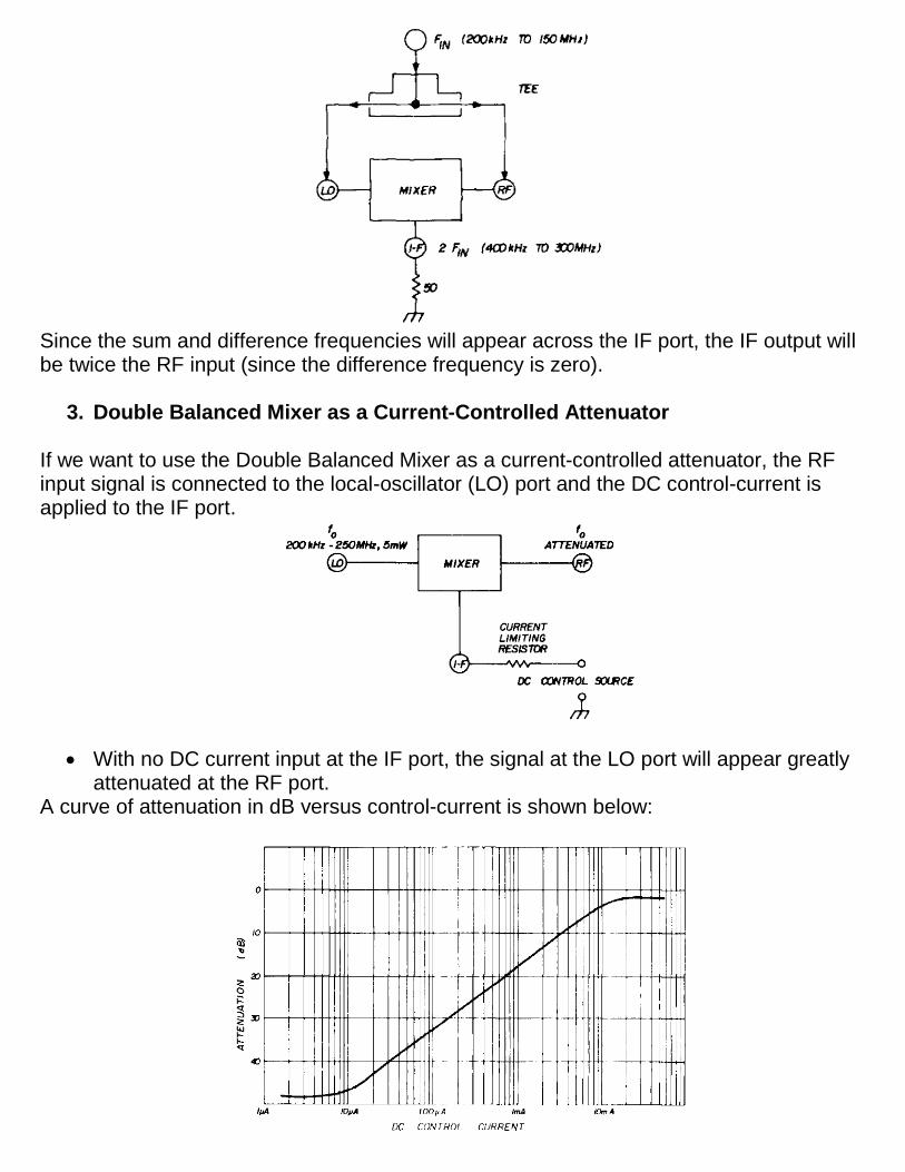
Since the sum and difference frequencies will appear across the IF port, the IF output will be twice the RF input (since the difference frequency is zero).
3. Double Balanced Mixer as a Current-Controlled Attenuator If we want to use the Double Balanced Mixer as a current-controlled attenuator, the RF input signal is connected to the local-oscillator (LO) port and the DC control-current is applied to the IF port.
With no DC current input at the IF port, the signal at the LO port will appear greatly attenuated at the RF port.
A curve of attenuation in dB versus control-current is shown below:
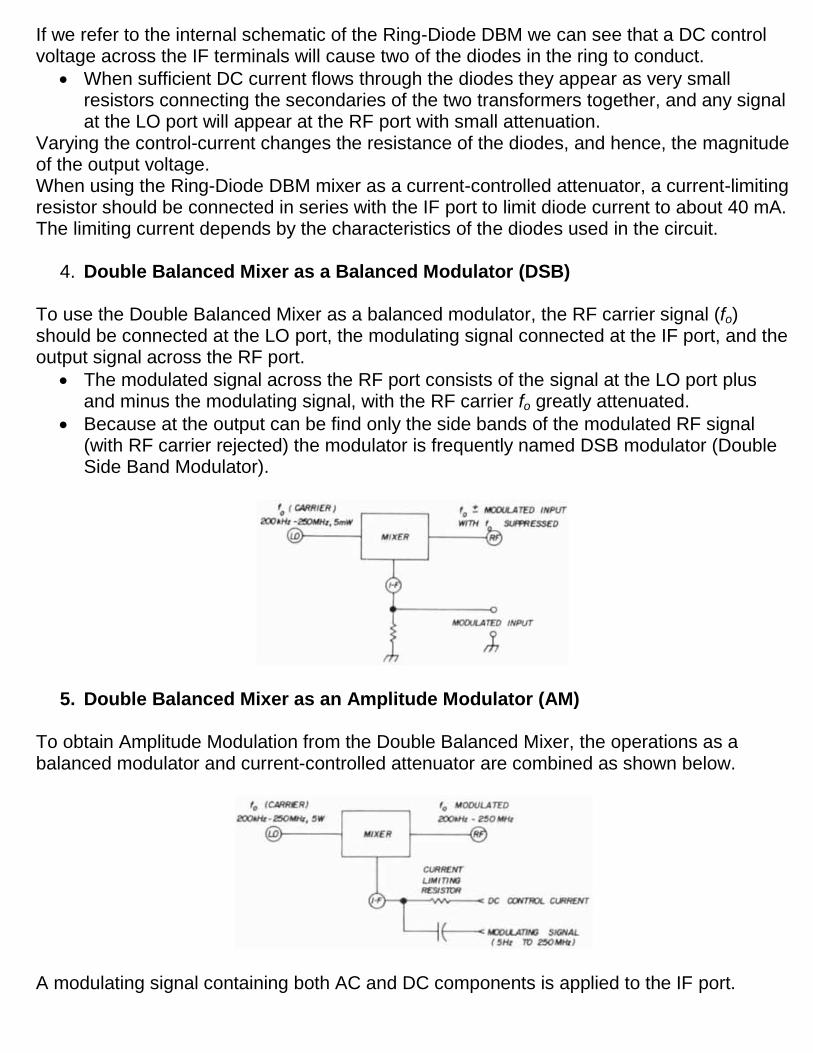
If we refer to the internal schematic of the Ring-Diode DBM we can see that a DC control voltage across the IF terminals will cause two of the diodes in the ring to conduct.
When sufficient DC current flows through the diodes they appear as very small resistors connecting the secondaries of the two transformers together, and any signal at the LO port will appear at the RF port with small attenuation.
Varying the control-current changes the resistance of the diodes, and hence, the magnitude of the output voltage. When using the Ring-Diode DBM mixer as a current-controlled attenuator, a current-limiting resistor should be connected in series with the IF port to limit diode current to about 40 mA. The limiting current depends by the characteristics of the diodes used in the circuit.
4. Double Balanced Mixer as a Balanced Modulator (DSB) To use the Double Balanced Mixer as a balanced modulator, the RF carrier signal (fo) should be connected at the LO port, the modulating signal connected at the IF port, and the output signal across the RF port.
The modulated signal across the RF port consists of the signal at the LO port plus and minus the modulating signal, with the RF carrier fo greatly attenuated.
Because at the output can be find only the side bands of the modulated RF signal (with RF carrier rejected) the modulator is frequently named DSB modulator (Double Side Band Modulator).
5. Double Balanced Mixer as an Amplitude Modulator (AM) To obtain Amplitude Modulation from the Double Balanced Mixer, the operations as a balanced modulator and current-controlled attenuator are combined as shown below.
A modulating signal containing both AC and DC components is applied to the IF port.
The AC components will produce sidebands and the DC component will vary the amplitude of the carrier appearing at the RF port. As an example for normal conditions, for 100% AM modulation, the modulating signal should be about 200mV rms and the DC control-current should be about 4 mA.
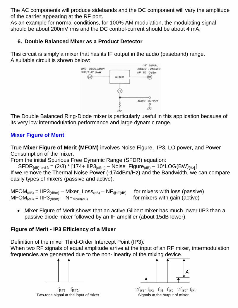
6. Double Balanced Mixer as a Product Detector This circuit is simply a mixer that has its IF output in the audio (baseband) range. A suitable circuit is shown below:
The Double Balanced Ring-Diode mixer is particularly useful in this application because of its very low intermodulation performance and large dynamic range. Mixer Figure of Merit True Mixer Figure of Merit (MFOM) involves Noise Figure, IIP3, LO power, and Power Consumption of the mixer. From the initial Spurious Free Dynamic Range (SFDR) equation: SFDR[dB] ord 3 = (2/3) * [174+ IIP3[dBm] – Noise_Figure(dB) – 10*LOG(BW)[Hz] ] If we remove the Thermal Noise Power (-174dBm/Hz) and the Bandwidth, we can compare easily types of mixers (passive and active). MFOM(dB) = IIP3(dBm) – Mixer_Loss(dB) – NF@IF(dB) for mixers with loss (passive) MFOM(dB) = IIP3(dBm) – NFMixer(dB) for mixers with gain (active)
Mixer Figure of Merit shows that an active Gilbert mixer has much lower IIP3 than a passive diode mixer followed by an IF amplifier (about 15dB lower).
Figure of Merit - IP3 Efficiency of a Mixer Definition of the mixer Third-Order Intercept Point (IP3): When two RF signals of equal amplitude arrive at the input of an RF mixer, intermodulation frequencies are generated due to the non-linearity of the mixing device.
Two-tone signal at the input of mixer Signals at the output of mixer
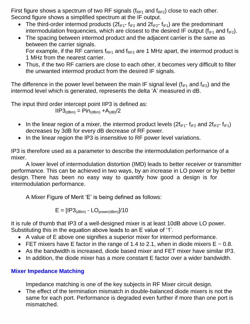
First figure shows a spectrum of two RF signals (fRF1 and fRF2) close to each other. Second figure shows a simplified spectrum at the IF output.
The third-order intermod products (2fIF1- fIF2 and 2fIF2- fIF1) are the predominant intermodulation frequencies, which are closest to the desired IF output (fIF1 and fIF2).
The spacing between intermod product and the adjacent carrier is the same as between the carrier signals. For example, if the RF carriers fRF1 and fRF2 are 1 MHz apart, the intermod product is 1 MHz from the nearest carrier.
Thus, if the two RF carriers are close to each other, it becomes very difficult to filter the unwanted intermod product from the desired IF signals.
The difference in the power level between the main IF signal level (fIF1 and fIF2) and the intermod level which is generated, represents the delta ‘A’ measured in dB. The input third order intercept point IIP3 is defined as:
IIP3(dBm) = Pin(dBm) +A(dB)/2
In the linear region of a mixer, the intermod product levels (2fIF1- fIF2 and 2fIF2- fIF1) decreases by 3dB for every dB decrease of RF power.
In the linear region the IP3 is insensitive to RF power level variations. IP3 is therefore used as a parameter to describe the intermodulation performance of a mixer.
A lower level of intermodulation distortion (IMD) leads to better receiver or transmitter performance. This can be achieved in two ways, by an increase in LO power or by better design. There has been no easy way to quantify how good a design is for intermodulation performance.
A Mixer Figure of Merit ‘E’ is being defined as follows:
E = [IP3(dBm) - LOpower(dBm)]/10
It is rule of thumb that IP3 of a well-designed mixer is at least 10dB above LO power. Substituting this in the equation above leads to an E value of ‘1’.
A value of E above one signifies a superior mixer for intermod performance.
FET mixers have E factor in the range of 1.4 to 2.1, when in diode mixers E ~ 0.8.
As the bandwidth is increased, diode based mixer and FET mixer have similar IP3.
In addition, the diode mixer has a more constant E factor over a wider bandwidth. Mixer Impedance Matching
Impedance matching is one of the key subjects in RF Mixer circuit design.
The effect of the termination mismatch in double-balanced diode mixers is not the same for each port. Performance is degraded even further if more than one port is mismatched.
Due to the imperfect isolation between the RF, LO, and IF ports, impedance matching must be conducted with many iterations back and forth between the three ports, especially between the LO and the RF ports, which usually has poor isolation.
The matching procedures should be as follows:
Matching of the LO port first: the LO injection is the main source controlling the operating status of a mixer. The operating status of a mixer never approaches a normal state until the LO port is well matched. The mismatch at the LO port can be improved simply by adding a 3dB pad attenuator. The LO power needs to be adjusted to overcome the loss.
Matching of the RF port second.
Repeating the two steps above until the variation between steps is negligible: owing to the imperfect isolation between the LO and RF port, the variation resulting from the matching at the RF port would change the matching status at the LO port, and vice versa.
Finally, matching the IF port. To achieve minimum conversion loss through the diode mixer and prevent harmonics reflecting back into the mixer, it is important that the IF output to be correctly matched to 50+j0 ohms resistance. It is not sufficient to properly match the IF port to the low order harmonics, but also over an extensive frequency range.
Using at the IF output a wideband Buterworth band-pass filter, with constant impedance through the pass-band, improves mixer performance.
The best mixer performance is obtained using at the IF output a diplexer which combines near ideal input matching with superior frequency response.
References: 1. RF Circuit Design for Wireless Applications – U. Rohde, D. Newkirk 2. Microawave Mixers - Stephen Maas 3. Nonlinear Microwave and RF Circuits - Stephen Maas 4. RF Design Guide – P. Vizmuller 5. RF Circuits Design - Theory and Applications - Ludwig, Bretchko 6. Practical Rf Circuit Design for Modern Wireless Systems – R. Gilmore, L. Besser 7. RF Circuit Design - W. Davis, Krishna Agarval 8. Mixers and Frequency Conversion – Besser Associates, Inc. 9. Designing a Super-High Dynamic Range Double-Balanced Mixer - Ed Oxner 10. High Level RF Mixers – D. Conway 11. Noise in High-Frequency Circuits and Oscillators - B. Schiek, I. Rolfes, H. Siweris 12. Novel Passive FET Mixers Provide Superior Dynamic Range – Minicircuits 13. Active Mixer Design Using Dual Gate MESFET - California Eastern Laboratories 14. Microwave Journal Magazine – 1997 – 2007 15. RF Design Magazine – 1992 – 2000 16. Ham Radio Magazine – 1968 – 1990 http://www.qsl.net/va3iul