Embed Size (px)
Citation preview

RF Energy Harvesting
Principle and Research

Outline
Future Work and Prospect
Energy Harvesting Techniques
• RF Energy
• Vibration Energy
• Solar Energy
Introduction and Motivation
2
Energy Harvesting Architecture
• System Evaluation
• Circuit Simulation
Performance Summary
• Antenna Design

Outline
Future Work and Prospect
Energy Harvesting Techniques
• RF Energy
• Vibration Energy
• Solar Energy
Introduction and Motivation
3
Energy Harvesting Architecture
• System Evaluation
• Circuit Simulation
Performance Summary
• Antenna Design

Introduction and Motivation
The size and power supply has been drastically
decreased for many devices in decades.
Solve the problem that the devices is at inaccessible
places. 4
Produce enough power to recharge the battery or
directly supply the electronics.

Applications
WSN in environment, agriculture, and structures
applications requires continuously available power
source with long lifetimes.
Self-powering with energy harvesting
5
Existing weather station
Satellite
Monitoring
Station

Applications
Biomedically implanted devices such as stimulator
and drug deliverer
The unchangeable power source decreases the
patient’s risk of death.
6

Outline
Future Work and Prospect
Energy Harvesting Techniques
• RF Energy
• Vibration Energy
• Solar Energy
Introduction and Motivation
7
Energy Harvesting Architecture
• System Evaluation
• Circuit Simulation
Performance Summary
• Antenna Design

Solar Vibration Radio Frequency
100mW/cm2
(Under sunlight) 100 mW/cm2 1 mW/cm2
Big area Cont. vibration
is needed Low power density
High power density Easy to apply on
Biomedical Technology
Easy to get from
ambient
6%~20% >95% 50%~70%
Energy Harvesting
8

RF Energy Harvester
9

Frequency 75Hz
Peak Efficiency ~90%
Output Voltage 3~5V
Output Power > 1mW
Vibration Energy Harvester
Application Circuit
Vibration Sensor
10

11
High Input Energy × Low Efficiency
× Large Area No Need Rectifier
Solar Energy Harvester
Solar Energy Harvester
Output
Voltage 4V
Peak
Efficiency ~20%
Output
Power > 1W
11
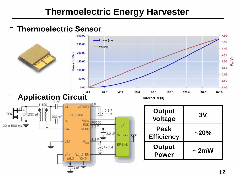
Thermoelectric Energy Harvester
Application Circuit
Thermoelectric Sensor
Output
Voltage 3V
Peak
Efficiency ~20%
Output
Power ~ 2mW
12

Outline
Future Work and Prospect
Energy Harvesting Techniques
• RF Energy
• Vibration Energy
• Solar Energy
Introduction and Motivation
13
Energy Harvesting Architecture
• System Evaluation
• Circuit Simulation
Performance Summary
• Antenna Design

RF Energy Harvesting Process
14
• Wide-Band Antenna
• Rectifier
500 MHz ~ 2.4 GHz
Output Voltage: 0.2~0.5 V
• DC-DC Converter
• Digital Controller
Transfer the original DC voltage (0.2~0.5 V) to a
Control the input impedance of DC-DC converter
to deliver a maximum power to the output.
higher usable level (e.g., 2 V)

The Limits and Current Practice (I)
Power Sources
Frequency Distance Transmitted power Received
Power Efficiency
[3] 677 MHz 4.1 km 960 kW 60 mW 16.3 %
[4] Digital TV 6.6 km N/A 15-23 mW N/A
The limits of received power in current practices:
Power Conversion Efficiency(PCE) of the Rectifier
[5] [6] [7] [8] [9]
Technology 0.3 mm 0.35 mm 0.5 mm 0.25 mm 0.18 mm
Max. PCE 33% 24% 28% 60% 67.5%
Sensitivity -14 dBm -10 dBm -17.8 dBm -22.6 dBm N/A
diodeout
out
lossout
out
in
outPCE
PP
P
PP
P
P
P

Broad-band matching means low Q resonant
The Limits and Current Practice (II)
× in
V2ant
V 2
matching1 Q
Broad-Band Matching
Low Vin will degrade the efficiency of Rectifier

The Limits and Current Practice (III)
17
Power Manager: DC-DC converter, control circuit.
• The limits of current practices: 80%
Hard to surpass.
We optimized the architectures mentioned in
[10]~[12].

Outline
Future Work and Prospect
Energy Harvesting Techniques
• RF Energy Harvesting
• Vibration Energy Harvesting
• Solar Energy Harvesting
Introduction and Motivation
18
Energy Harvesting Architecture
• System Evaluation
• Circuit Simulation
Performance Summary
• Antenna Design

Architecture
Single-Band (900MHz) RF Energy Harvesting System
19
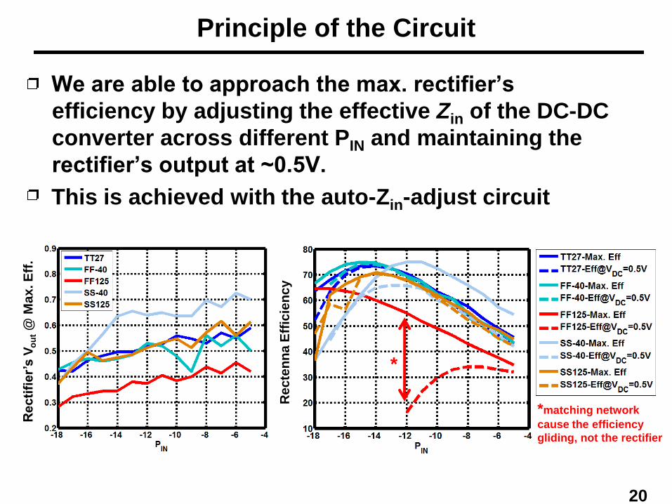
Principle of the Circuit
We are able to approach the max. rectifier’s
efficiency by adjusting the effective Zin of the DC-DC
converter across different PIN and maintaining the
rectifier’s output at ~0.5V.
This is achieved with the auto-Zin-adjust circuit
Re
cti
fie
r’s V
ou
t @
Ma
x. E
ff.
Re
cte
nn
a E
ffic
ien
cy
*matching network
cause the efficiency
gliding, not the rectifier
*
20
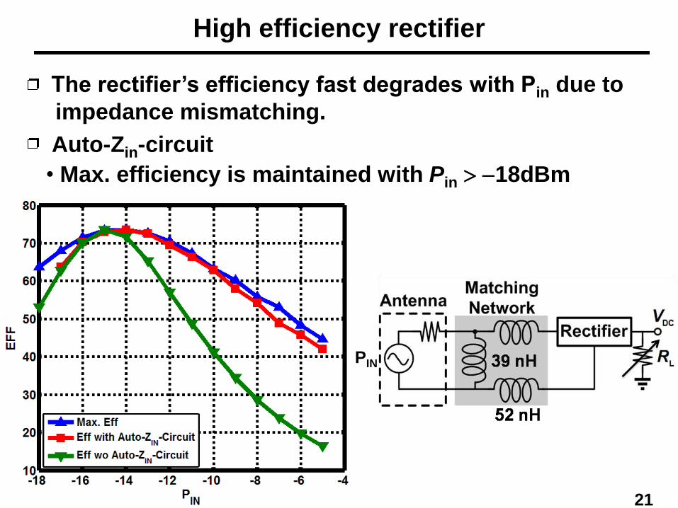
High efficiency rectifier
Auto-Zin-circuit
PIN
21
The rectifier’s efficiency fast degrades with Pin due to
• Max. efficiency is maintained with Pin > -18dBm
impedance mismatching.

Auto-Zin-Adjust circuit
Adjusts the length of Toff and therefore the effective Zin
of the DC-DC converter to maintain the rectifier’s
efficiency
• If Vd > Vout Zin is too high the counter will count
down
To decrease Toff, increase average load cur., and
decrease effective RL
• If Vd < Vout Zin is too low the counter will count up
To increase Toff, decrease average load cur., and
increase effective RL
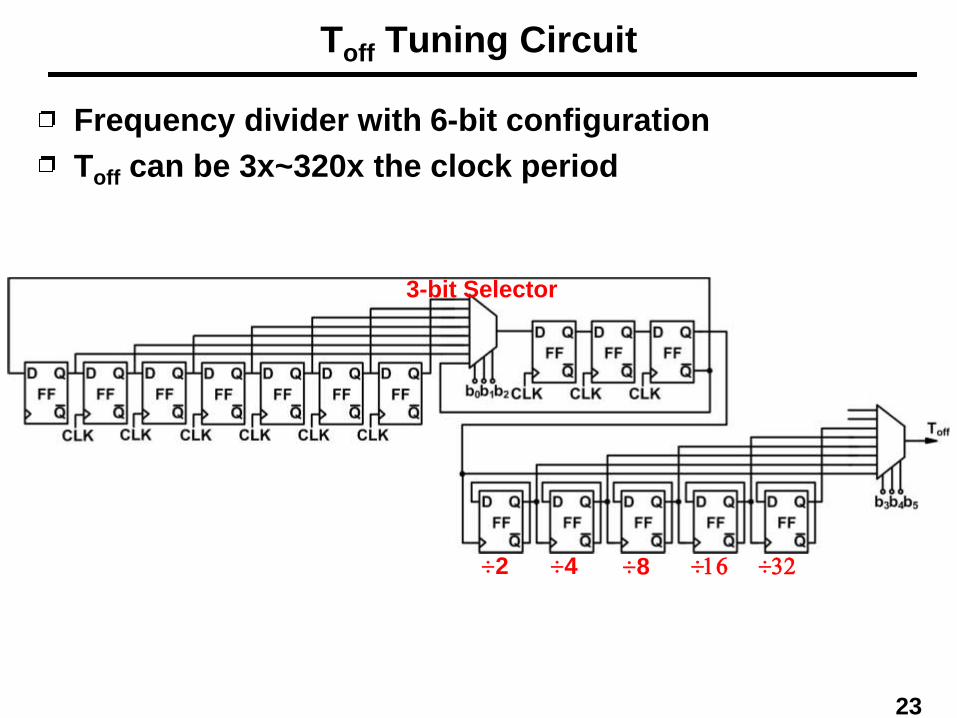
Toff Tuning Circuit
Frequency divider with 6-bit configuration
Toff can be 3x~320x the clock period
3-bit Selector
÷2 ÷4 ÷8 ÷16 ÷32
23

Tn,Tp generator
Tn generator:3x of clock period
Tp generator :1x of clock period
24

• Effmatching = = 87%
• Effrectifier = = 83%
• EffDC_DC = = 74%
Performance Calculation
in_rectifier
in_matching
P
P
in_DC_DC
in_rectifier
P
P
out_DC_DC consumption
in_DC_DC
P P
P
-
Eff_totsl = Effmatching × Effrectifier × EffDC_DC = 54%
25
Power Summary: estimated by Friis equation
Outdoor (GSM/TV base station): 490 mW
Indoor (Cell Phone and WLAN): 202.5 mW
Received power at least 100 mW.

Startup Circuit
During startup phase, there is no load current. With
enough Pin (-15dBm at TT corner 27oC), the
rectifier’s output can reach > 0.6V.
• Using an oscillator that is able to oscillate with its
supply voltage less than 0.6V to control the DC-DC
converter, the output voltage can be boosted to 1.2V
• This zero startup circuit work with AC sources (ex.
RF or vibration) without precharge.
26

Outline
Future Work and Prospect
Energy Harvesting Techniques
• RF Energy Harvesting
• Vibration Energy Harvesting
• Solar Energy Harvesting
Introduction and Motivation
27
Energy Harvesting Architecture
• System Evaluation
• Circuit Simulation
Performance Summary
• Antenna Design

Antenna a.
Frequency (GHz)
• Frequency
DTV 470~840
500 MHz~900 MHz
• Size
190×15 mm2
• Max. Gain
> 2dB S
11 (
dB
)
GSM 900
28

Antenna b.
Frequency (GHz)
GSM900
DCS1800, GSM1900,
WiMAX2350, WLAN2400
GPS1575
• Frequency
GSM/GPS/Wi-Fi
• Size
90×50 mm2
• Max. Gain
> 2dB S
11 (
dB
)
29

Antenna c.
Frequency (GHz)
802.11a
• Frequency
3 GHz~10 GHz
• Size
30×30 mm2
• Max. Gain
> 4dB
S11 (
dB
)
30

Antenna
Size Comparison
31
[13] a b c
[13]

Outline
Future Work and Prospect
Energy Harvesting Techniques
• RF Energy Harvesting
• Vibration Energy Harvesting
• Solar Energy Harvesting
Introduction and Motivation
32
Energy Harvesting Architecture
• System Evaluation
• Circuit Simulation
Performance Summary
• Antenna Design

The performance is much better than others.
State-of-the-Art (RF)
This Work RF[14] RF[15] RF[16]
Process 0.18mm 130nm 90nm 250nm
Frequency 890-920MHz 915MHz/1GHz 915MHz 906MHz
Min. Input
Power -18dBm N/A -18dBm -22.6dBm
Max. Output
Power 113mW
@ - 5dBm* 140mW 9mW N/A
Matching Eff. 87.8%
@ -15dBm N/A 56.8% N/A
Rectifier Eff. 83%
@ -15dBm 65%
16% @ -15dBm
60% @ - 7dBm
DC-DC Eff. 74.4%
@ -15dBm 75% N/A N/A
Max.Total Eff. 54.2%
@ -15dBm N/A N/A
60% @ - 7dBm
Output Voltage 2V 1.2V 1.2V @ RL=1M 1.4V @ RL=1.32M
*The total Eff is 36% @-5dBm
33

Outline
Future Work and Prospect
Energy Harvesting Techniques
• RF Energy Harvesting
• Vibration Energy Harvesting
• Solar Energy Harvesting
Introduction and Motivation
34
Energy Harvesting Architecture
• System Evaluation
• Circuit Simulation
Performance Summary
• Antenna Design

Future Work
Construct an over-1mW energy harvesting system by
combining multi-harvester.
• Intelligent frequency-hopping RF energy harvesting
system
Analyze trade-off between efficiency and wideband
matching, targeting max. power transfer
Use power sensor to search for band with max.
energy and dynamically tune the matching network
• Multi-sources energy harvesting power manager
Adjust ff1 of DC-DC converter to change the
loading for each ZHout of different harvesters
35

Milestones
36
1st Year
• Fully study all possible solutions, and finish the
energy harvesting circuit designs for the RF power.
2nd Year
• Use power sensor to search for band with max.
energy and dynamically tune the matching network
3rd Year
• An mW-level (>1mW) energy harvester prototype will
be presented.
• By sensing the frequency band with the most sufficient power, we will switch the corresponding rectenna to
a single DC-DC converter.
• Survey other energy solutions for researching
multi-sources energy harvesting power manager
Reference (I)
[1] Federal Communications Commission (FCC) Codes of Regulation, U.S., Part 15,
Low Power Broadcasting, available at < www.fcc.gov>.
[2] U. Bergqvist et al., “Mobile telecommunication base stations-exposure to
electromagnetic fields, Report of a short term mission within COST-244bis,”
COST-244bis short term mission on base station exposure, 2000.
[3] Alanson Sample and Joshua R. Smith, “Experimental results with two wireless
power transfer systems,” Proceedings of the 4th international conference on
Radio and wireless symposium, pp. 16-18, Jan. 2009.
[4] H. Nishimoto, Y, Kawahara, and T. Asami ,“Prototype implementation of
wireless sensor network using TV broadcast RF energy harvesting,”
Proceedings of the 12th ACM international conference adjunct papers on
Ubiquitous computing, pp. 355-356, Sept. 2010.
[5] T. Umeda, H. Yoshida, S. Sekine, Y. Fujita, T. Suzuki, and S. Otaka, “A 950-MHz
rectifier circuit for sensor network tags with 10-m distance,” IEEE J. Solid-State
Circuits, vol. 41, no. 1, pp. 35-41, Jan. 2006.
[6] H. Nakamoto, D. Yamazaki, T. Yamamoto, H. Kurata, S. Yamada, K. Mukaida, T.
Ninomiya, T. Ohkawa, S. Masui, and K. Gotoh, “A passive UHF RF identification
CMOS tag IC using ferroelectric RAM in 0.35- um technology,” IEEE J. Solid-
State Circuits, vol. 42, no. 1, pp. 101-110, Jan. 2007.
[7] U. Karthaus and M. Fischer,“Fully integrated passive UHF RFID transponder IC
with 16.7- W minimum RF input power,”IEEE J. Solid-State Circuits, vol. 38,
no. 10, pp. 1602-1608, Oct. 2003.
37

Reference (II)
[8] T. Le, K. Mayaram, and T. Fiez, “Efficient Far-Field Radio Frequency Energy
Harvesting for Passively Powered Sensor Networks,” IEEE J. Solid-State
Circuits, vol. 43, no. 5, pp. 1287-1302, May 2008.
[9] Koji Kotani, Atsushi Sasaki, and Takashi Ito, “High-Efficiency Differential-Drive
CMOS Rectifier for UHF RFIDs,” IEEE J. Solid-State Circuits, vol.44, no.11, pp.
3011-3018, Nov. 2009.
[10] E. Carlson, K. Strunz, B. Otis, “20mV Input Boost Converter for Thermoelectric
Energy Harvesting,” Digest of Symposium on VLSI Circuits, pp.162-163, June
2009.
[11] I. Doms, P. Merken, C. Van Hoof, and M. C. Schneider, “Comparison of DC-DC
converter architectures of power management circuits for thermoelectric
generators,” EPE, pp. 1-5, Sept. 2007.
[12] I. Doms, P. Merken, R. P. Mertens, and C. Van Hoof, “Capacitive power-
management circuit for micropower thermoelectric generators with a 2.1mW
controller,” ISSCC Dig. Tech. Papers, pp. 300-615, Feb. 2008.
[13] P. Li, X. Jiang, X. Liu, H. Shi, and X. Lu,” Research on the relation between
Printed Log-Periodic Antenna's feed and bandwidth,” IEEE Signals Systems
and Electronics, vol. 2, pp. 1-3, 2010.
[14] S. O’Driscoll, S. A. Poon, and T. H. Meng, “A mm-sized implantable power
receiver with adaptive link compensation,” IEEE ISSCC Dig. Tech. Papers,
pp.294–295, Feb. 2009
38

Reference (III)
[15] G. Papotto, F. Carrara, and G. Palmisano, “A 90-nm CMOS Threshold-
Compensated RF Energy Harvester,” IEEE J. Solid-State Circuits, vol. 46, no. 9,
pp. 1958-1997, Sept. 2011.
[16] T. Le, K. Mayaram, and T. Fiez, “Efficient far-field radio frequency energy
harvesting for passively powered sensor networks,” IEEE J. Solid-State Circuits,
vol. 43, no. 5, pp. 1287–1302, May 2008
39