Embed Size (px)
Citation preview

GILTRAP GENERATION II RF CONTROL SYSTEM
February 2008
Introduction..................................................................................................................................................... 2 Control Mode Options..................................................................................................................................... 2 Remote Display Layout ................................................................................................................................... 3 Controller Layout............................................................................................................................................ 3
Operation Section..........................................................................................................4 Overview ......................................................................................................................................................... 4 Valve Over-ride Function ............................................................................................................................... 4
REMOTE DISPLAY SCREENS................................................................................................................................. 5 Screen Symbols ............................................................................................................................................... 5 Start-up Screen................................................................................................................................................ 5 Standard Mode Screen .................................................................................................................................... 6 Weight Mode Screen ....................................................................................................................................... 7 Distance Mode Screen..................................................................................................................................... 8 Speed Mode Screen ......................................................................................................................................... 9 Scales Screen................................................................................................................................................. 10
Installation Section......................................................................................................11 Component Layout ........................................................................................................................................ 11 Remote Display Mounting & Power Supply.................................................................................................. 12 Forage Wagon Controller & Power Supply.................................................................................................. 12 Setting the RFID Number.............................................................................................................................. 14 Fitting the Power Module Circuit Board ...................................................................................................... 15 Fitting the Wheel Sensor ............................................................................................................................... 15 Fitting the Load Cells ................................................................................................................................... 16 Setting System Parameters............................................................................................................................ 17 Checking Setup Parameters .......................................................................................................................... 21 Factory Parameter Settings .......................................................................................................................... 22 Final Check................................................................................................................................................... 23

Generation II RF Control System – Operating, Installation & Technical Manual
2
Introduction The Giltrap Generation II RF Control System consists of a Controller that is mounted on the wagon that uses wireless technology to relay data such as feed rate, load weights or feed-out amounts (depending on options purchased) from the wagon and displays it on the Remote Display mounted near the operator on the tractor, allowing the operator to control the feed rate using different modes. Powerfully capable, yet simple to use, the controller has large buttons and an easy-to-read display allowing the operator to constantly monitor, and adjust the feed rate when needed, all while on the move.
Control Mode Options The system has a total of five different operation modes available. The availability of these are dependant on the hardware options fitted to the machine. Hardware available: Load cells – for weight readings Solenoid coil – for floor control Wheel sensor – for ground speed calculation Standard Mode The operator controls the feed rate through a percentage range from 0 to 100%. Requires a solenoid coil to be fitted. Weight Mode The operator can enter a target weight to feed. The feed rate control is the same as Standard mode. Requires load cells and solenoid coil to be fitted. Distance Mode (also known as Fully Automatic mode) The wagon will unload the required amount over the required distance, and will compensate for changes in ground speed. Requires load cells, solenoid coil and wheel sensor to be fitted. Speed Mode The operator controls the feed out rate through a percentage range from 0 to 100% and the feed rate is automatically adjusted according to ground speed. Requires a solenoid coil and wheel sensor to be fitted. Load cells are optional. Scales Mode Only has a weight display. Requires load cells to be fitted. Floor rate is controlled manually.
RF Gen II System Technical Manual Rev02_08.doc

Generation II RF Control System – Operating, Installation & Technical Manual
3
Remote Display Layout Display screen
UP button GO button STOP button RIGHT button MODE button
Power switch TARE/GROSS button
DOWN button Power plug
LEFT button ZERO button
Power light Signal light Signal light Valve light
Controller Layout
Weight connection Valve connection Power connection
P ower ON utton b
P ower OFF
utton
b
RF Gen II System Technical Manual Rev02_08.doc

Generation II RF Control System – Operating, Installation & Technical Manual
4
Operation Section
Overview Assuming installation (page 11 – 23) has been completed, the power for the system is controlled by the switch adjacent to the Remote Display.
1. Turn the switch on to provide power to the Remote Display and the wagon. 2. If the wagon is disconnected, press and hold the ON button on the Controller for one
second. The Controller is now operating on its own battery. 3. Begin loading the wagon. See more detailed information regarding modes and
buttons. 4. Once completed loading, connect the wagon to the tractor and connect the 7-pin
plug. 5. Once ready to feed, select the appropriate mode and press GO button. You are now
ready to proceed. Note: The Controller power light will illuminate when the ON button is pressed or the wagon is plugged into the tractor. To turn off, the wagon must be un-plugged before pressing the OFF button.
Valve Over-ride Function When a solenoid is fitted for floor control, a manual over-ride function will also be provided. Note: This function over-rides all RF floor rate control. Use ¼ - ½ turn adjustments per time. Do not over-adjust. For electronic operation with RF control, the screw adjuster must be unscrewed all the way out (anti-clockwise) and the locking ring tightened.
IMPORTANT Manual over-ride located beneath this
cover
To operate in case of electronic malfunction, undo locking ring and
screw in adjuster.
Use ¼ - ½ turn adjustments.
Locking ring Over-ride adjuster
Label on cover
RF Gen II System Technical Manual Rev02_08.doc

Generation II RF Control System – Operating, Installation & Technical Manual
5
Remote Display Screens
Screen Symbols Apart from usual text characters, the screen can display other symbols at various times.
The battery symbol indicates when the system is operating on its own battery. The voltage display indicates the condition of the battery.
The antenna symbol indicates when the Controller and Remote Display have communication between them. This must show at all times for successful operation.
Start-up Screen When the Remote Display is powered up, the start-up screen is displayed for 3 seconds as below. After this the screen will change to the operating screen. GILTRAP GEN II
CONTROL SYSTEM
Channel: 1 Rev 3.4
Remote Display software
revision Remote Display RF channel
If the wagon is not connected i.e. not getting power from the tractor, the controller will not start. The screen below will display until communication has begun by plugging in the wagon or pressing and holding the GO button on the controller for 1 or more seconds. After establishing communication, it will proceed directly to the next screen.
Waiting for
RF Forage Wagon Communications...
Once communication has begun between the devices, a screen similar to the one below will show.
STOP Std 12.5V
FEED RATE: 50%
DISPENSED: 0kg
GROSS: 2950kg
The modes that are available are dependant on the hardware options fitted to the machine.
RF Gen II System Technical Manual Rev02_08.doc

Generation II RF Control System – Operating, Installation & Technical Manual
6
Standard Mode Screen In standard mode, the feed rate is shown as a percentage. A range of 1-100% is available with 100% being maximum feed rate. This rate is shown on the top line of the screen. This mode is useful for general operation and is the most simple to use. Screen Features:
The top line shows the feed rate.
FEED RATE: 50%
DISPENSED: 1050kg
GROSS: 2950kg
STOP Std 12.5V
FEED RATE: 50%
STOP Std
System battery indicator
Product amount in machine
Battery voltage
Dispensed amount
Connectivity status
System status
Mode of operation
Feed Rate
Rate control only Rate control with load cells fitted
The bottom line of the screen shows the status of the system (STOP), the mode of operation (Std)
and connectivity status. Additional features that show if load cells are fitted:
The second line will show the weight dispensed since GO was pressed.
The third line will display the present wagon weight. This may be gross or tare.
The bottom line of the screen shows the status of the system (STOP), the mode of operation (Std), the battery voltage (highest voltage available to the unit. When disconnected from the tractor, this will be the internal battery voltage), and connectivity status.
Operating Notes: Screen Warnings:
The operator can adjust the rate percentage figure by pressing UP or DOWN on the keypad. The operator can select between gross and tare weight to be displayed by pressing TARE/GROSS on the keypad. The operator can zero only the dispensed weight by pressing GO on the keypad. The operator can start and stop the feed-out by pressing GO and STOP on the keypad. The operator can switch to other available operating modes by pressing MODE on the keypad. The operator can zero the gross and dispensed weight by pressing ZERO on the keypad.
“WAGON POWER NOT CONNECTED” will flash on the display if the GO button on the Remote
Display is pressed without the wagon being plugged into the tractor and/or power not getting from the tractor to the Controller.
RF Gen II System Technical Manual Rev02_08.doc

Generation II RF Control System – Operating, Installation & Technical Manual
7
Weight Mode Screen In Weight mode, the feed rate is shown as a percentage. A range of 1-100% is available with 100% being maximum feed rate. This rate is shown on the top line of the screen. The operator can enter a target weight to feed before a beeper will sound, the wagon floor will stop moving and the system status will return to STOP. Screen Features:
FEED RATE: 50%
TO FEED: 560kg
GROSS: 2950kg
STOP Weight 12.5V
Mode of operation System status System battery indicator
Target weight to feed
Product weight in machine
Connectivity status
Battery voltage
Feed Rate
The top line shows the feed-out rate.
The second line shows the weight to feed out before a beeper sounds.
The third line shows the weight of the current load. This may be gross or tare.
The bottom line of the screen shows the status of the system (STOP), the mode of operation
(Weight), the battery voltage (highest voltage available to the unit. When disconnected from the tractor, this will be the internal battery voltage), and connectivity status.
Operating Notes:
The operator can alter the feed-out rate by adjusting the rate percentage by pressing UP or DOWN on the keypad. The operator can adjust the weight to be dispensed by adjusting the ‘TO FEED’ figure. This is done by pressing UP or DOWN on the keypad when the ‘TO FEED’ figure is underlined. Use the RIGHT or LEFT button to move the underline cursor. The operator can start and stop the feed-out by pressing GO and STOP on the keypad. The operator can switch to other available operating modes by pressing MODE on the keypad. The operator can select between gross and tare weight to be displayed by pressing TARE/GROSS on the keypad. The operator can zero the gross and dispensed weight by pressing ZERO on the keypad.
Screen Warnings:
“WAGON POWER NOT CONNECTED” will flash on the display if the GO button on the Remote Display is pressed without the wagon being plugged into the tractor and/or power not getting from the tractor to the Controller.
RF Gen II System Technical Manual Rev02_08.doc

Generation II RF Control System – Operating, Installation & Technical Manual
8
RF Gen II System Technical Manual Rev02_08.doc
Distance Mode Screen In Distance mode, the feed rate is automatically set by dispensing feed over a set distance. Screen Features:
The top line shows the weight to feed out.
The second line shows the distance over which to feed this weight.
The third line shows the present wagon weight. This may be gross or tare.
The bottom line of the screen shows the status of the system (STOP), the mode of operation (Dist), the battery voltage (highest voltage available to the unit. When disconnected from the tractor, this will be the internal battery voltage), and connectivity status.
Operating Notes: Screen Warnings:
“WAGON POWER NOT CONNECTED” will flash on the display if the GO button on the Remote Display is pressed without the wagon being plugged into the tractor and/or power not getting from the tractor to the Controller.
“INCREASE GROUND SPEED” will flash on the display when the wagon is travelling too slow and causing
the machine to overfeed. Note that ground speed needs to increase not tractor revs.
“DECREASE GROUND SPEED” will flash on the display when the wagon is travelling faster than the machine can feed. Note that ground speed needs to decrease not tractor revs.
TO FEED: 1800kg
LENGTH: 100m
GROSS: 2950kg
STOP Dist 12.5V
Mode of operation
System status
Feed to dispense
Distance to travel
Product weight in machine
Connectivity status
Battery voltage
System battery indicator
The operator can adjust the weight to be dispensed by adjusting the ‘TO FEED’ figure. This is done by pressing UP or DOWN on the keypad when the ‘TO FEED’ figure is underlined. Use the RIGHT or LEFT button to move the underline cursor. The operator can adjust the distance to feed the weight over by adjusting the ‘LENGTH’ figure. This is done by pressing UP or DOWN on the keypad when the ‘LENGTH’ figure is underlined. Use the RIGHT or LEFT button to move the underline cursor. The operator can start or stop the operation by pressing GO or STOP on the keypad. If the feed bins are unequal in length, enter the total length of the bins in the ‘LENGTH’ figure and the total amount to feed in the ‘TO FEED’ figure. After travelling the first bin, press STOP on the keypad. The display will change from RUN to WAIT. You can then travel forward or backward without the distance changing. Press GO to continue or press and hold the STOP button for 3 or more seconds to reset the system status to STOP. The system will automatically return to STOP mode after counting down the distance to zero.
The operator can switch to other available operating modes by pressing MODE on the keypad. The operator can select between gross and tare weight to be displayed by pressing TARE/GROSS on the keypad. The operator can zero the gross and dispensed weight by pressing ZERO on the keypad.

Generation II RF Control System – Operating, Installation & Technical Manual
9
Speed Mode Screen In Speed mode, the machine will maintain a consistent feed-rate relative to ground speed. The feed rate percentage is adjustable from 1 – 100%.
FEED RATE: 50%
STOP Speed
FEED RATE: 50%
DISPENSED: 940kg
GROSS: 3540kg
STOP Speed 12.5V
Battery voltage
System battery indicator
Connectivity status
Dispensed amount
Product weight in machine
Feed Rate
System status
Mode of operation
Rate control only
Rate control with
load cells fitted Screen Features:
The top line shows the feed rate.
The bottom line of the screen shows the status of the system (STOP), the mode of operation (Speed) and connectivity status.
Additional features that show if load cells are fitted:
The second line shows the weight fed out since the wagon was loaded.
The third line shows the present wagon weight. This may be gross or tare.
The bottom line of the screen shows the status of the system (STOP), the mode of operation (Speed), the battery voltage (highest voltage available to the unit. When disconnected from the tractor, this will be the internal battery voltage), and connectivity status.
Operating Notes:
The operator can alter the feed-out rate by adjusting the rate percentage by pressing UP or DOWN on the keypad. The operator can adjust the weight to be dispensed by adjusting the ‘TO FEED’ figure. This is done by pressing UP or DOWN on the keypad when the ‘TO FEED’ figure is underlined. Use the RIGHT or LEFT button to move the underline cursor. The operator can start or stop the feed-out by pressing GO or STOP on the keypad. The operator can zero only the dispensed weight by pressing GO on the keypad. The operator can switch to other available operating modes by pressing MODE on the keypad. The operator can select between gross and tare weight to be displayed by pressing TARE/GROSS on the keypad. The operator can zero the gross and dispensed weight by pressing ZERO on the keypad.
Screen Warnings: “WAGON POWER NOT CONNECTED” will display if the GO button on the Remote Display is
pressed without the wagon being plugged into the tractor and/or power not getting from the tractor to the Controller.
RF Gen II System Technical Manual Rev02_08.doc

Generation II RF Control System – Operating, Installation & Technical Manual
10
Scales Screen In Scales mode, the screen will only display weight figures. This mode is used when no rate control is fitted to the wagon. No other modes are available if only load cells are fitted. The operator can enter a target weight to feed when a beeper will sound, the wagon floor will stop moving (if the floor control solenoid is fitted) and the system status will return to STOP. Features:
TO FEED: 560kg
DISPENSED: 733kg
GROSS: 3440kg
STOP Scales
Mode of operation
System status 12.5V
System battery indicator
Amount in machine
Connectivity status
Battery voltage
Target weight to feed
Dispensed amount
The top line shows the weight to feed out before a beeper sounds.
The second line shows the weight dispensed since GO was pressed.
The third line shows the tare or gross weight in the machine.
The bottom line of the screen shows the mode of operation (Scales), the battery voltage (highest
voltage available to the unit. When disconnected from the tractor, this will be the internal battery voltage), and connectivity status.
Operating Notes: The operator can adjust the weight to be dispensed by adjusting the
‘TO FEED’ figure. This is done by pressing UP or DOWN on the keypad when the ‘TO FEED’ figure is underlined. Use the RIGHT or LEFT button to move the underline cursor. The operator can select between gross and tare weight to be displayed by pressing TARE/GROSS on the keypad. The operator can zero only the dispensed weight by pressing GO on the keypad. To allow the dispensed weight to accumulate and the target feed weight to work, the operator must press GO before commencing feeding. The operator can zero the gross weight and dispensed weight by pressing ZERO on the keypad.
Screen Warnings:
None
RF Gen II System Technical Manual Rev02_08.doc

Generation II RF Control System – Operating, Installation & Technical Manual
11
RF Gen II System Technical Manual Rev02_08.doc
Installation Section
Component Layout
Valve cable #TCS-V2CABVAL
Data cable (1m) #TCS-V2CABWGT
Wheel sensor (5m) #TCS-OEM-PROX
Load cells (4 or 6) #ES-WLY00003P
Weight module #TCS-V2WGTMOD
Remote display #TCS-V2DISP
Valve assembly #HYSUPERVC-DPBM
Power module #TCS-V2PB
Cable from switch to tractor plug (2m)
Controller power cable (1m) #TCS-V2CABCON
Battery #TCS-BATTERY2
7 core cable (5.5m) with plug #TCS-LOOM2
Cab switch
12 – 24VDC Supply [Tractor battery preferably]
Brown - Positive Blue - Negative
5A Fuse
Battery cable (0.55m) #TCS-V2CABBAT
Controller #TCS-V2CONTR
Cable from battery to switch (5m)
5A Fuse
Tail lights
7 pin plug #PLUG7PINM
Install loom #TCS-LOOM1 (with box) Install loom #TCS-LOOM1V2 (no box)
#LIGHTLED-LH #LIGHTLED-RH
Remote display cable#TCS CABLE

Generation II RF Control System – Operating, Installation & Technical Manual
12
Remote Display Mounting & Power Supply The Remote Display is designed to be mounted in the tractor cab and be easily accessible to the driver. It contains a radio frequency (RF) communication device to control the Forage Wagon Controller (Controller). It will require shielding from the weather elements of sun and rain etc. The Remote Display requires 12-24 volts DC to operate. It will typically only draw 0.2A. The power supply will originate from the tractor battery as part of the installation loom (supplied with the machine).
Forage Wagon Controller & Power Supply The Forage Wagon Controller is powered from the tractor while operating. When disconnected from the tractor, it draws power from its own sealed lead acid battery. No installation wiring is required on the Forage Wagon. The tractor requires an installation loom (supplied) which provides a switched and fused positive and negative supply from the tractor battery to the rear 7-pin socket. The tractor battery is the best power supply point as it provides the most stable and “quiet” power source.
Note: If pin 5 is already used, connect the blue wire into pin 3 and do the same with the trailer plug.
RF nwiregative supply from
ing loom (BLUE)
RF positive supply from wiring loom (BROWN)
There are three CPC connectors on the Controller. If a connector is not used, place the sealing cap over it.
RF Gen II System Technical Manual Rev02_08.doc

Generation II RF Control System – Operating, Installation & Technical Manual
13
Mounting the Modules Modules should be mounted as illustrated. • Power wires should be kept separate where possible from the load cell cables. • Only 2 screws are required at opposite corners of each module. • Keep all cables clear of moving parts.
Control Module
Control Module mounting bracket
Battery Weight Module
Power Module
Battery base plate
Run power cables this side
Run load cell cables this side
RF Gen II System Technical Manual Rev02_08.doc

Generation II RF Control System – Operating, Installation & Technical Manual
14
Setting the RFID Number The RFID Number setup screen is used to assign a wireless address to the Controller. This feature is available to prevent interference between two systems when they are operated in close proximity to each other. To access the Remote Display RFID screen, re-power the display and press and hold the MODE button until a setup screen appears.
*** SETUP ***
RFID Number
1.00
The operator can press the UP button or the DOWN button to adjust this value. Press GO to enter then STOP to escape. Re-power the Remote Display to access the new channel. Controller Settings After removing the Controller cover, a DIP switch with 8 white switches is visible. DIP switches
• The D.I.P. (dual inline plastic) switches which are labelled 1 to 8 are used to select the RF channel ID.
• The switch is considered to be ‘on’ when switched to the right hand side.
• The channel ID of the Controller MUST match the software setting of the Remote Display.
• If the channel ID is changed in either the Remote Display or Controller then you must re-power both devices for the new setting to take effect. To re-power the Controller, unplug the POWER cable for 5 seconds.
• The DIP switch settings are shown in the following table.
RFID # 0 1 2 3 4 5 6 7 8 9 10 11 12 13 14 1 2 1 3 1 2 1 4 1 1 1 3 1 2 2 3 3 2 4 2 2 4 3 3 Switch
On Non
e
3 4 4 4
RF Gen II System Technical Manual Rev02_08.doc

Generation II RF Control System – Operating, Installation & Technical Manual
15
Fitting the Power Module Circuit Board The power board will need to be fitted if load cells are fitted. It is fitted into the power module. • Open the Power Module lid. • Remove the wire joining block. • Fit the circuit board with the supplied screws. • Attach the wires as noted on the board.
Fitting the Wheel Sensor • The wheel (proximity) sensor has to be adjusted halfway between the range of being
always on and always off. This is approximately 5mm between the end of the sensor and the wheel plate.
• Take care when running the cable that there is enough slack to allow the axle to fully oscillate.
Approx. 5mm
RF Gen II System Technical Manual Rev02_08.doc

Generation II RF Control System – Operating, Installation & Technical Manual
16
Fitting the Load Cells • Fit the studs to the load cell first before fitting the load cells to the machine using the bolts
provided. • Lower the top half of the wagon onto the studs. • Tighten the top nut then back off ½ turn. • Route the wiring through the pipe/brackets provided through to the junction box taking
care to keep the wiring tidy and away from moving objects.
Concave washer Convex washer Load cell Stud and nut
Recommended Load Cell Bolt Torque Settings
M20 - 280 ft/lbs or 380Nm
M24 - 490 ft/lbs or 660Nm
Note: If installing PT brand load cells, there will be two extra blue and brown wires. Connect the Sense +ve (brown) together with Excitation +ve (red) and Sense –ve (blue) together with Excitation –ve (black).
Weight Module Connection When fitting load cells or a wheel sensor, see below for fitting information about connecting wires into the weight module.
Insert screw driver for top layer here Top layer Insert screw driver for bottom layer here Bottom layer
RF Gen II System Technical Manual Rev02_08.doc

Generation II RF Control System – Operating, Installation & Technical Manual
17
Setting System Parameters Parameters are required to be set for the machine to function correctly. Entering Configuration Screens
• To enter set-up, press TARE/GROSS and ZERO together for 4 seconds or until the set-up screen appears.
• Press UP or DOWN to adjust the parameter. • Press MODE to move to the next configuration screen. It will save what is displayed
on the screen. • Press STOP to exit the configuration screens.
Scale Damping Value The “Scale Damping Value” parameter is a weighting value over which the weight is averaged. A higher value will display a smoother weight display but won’t react to weight changes as quickly.
*** SETUP ***
Scale Damping Value
1.00
RANGE: 1-15 The operator can press UP or DOWN to adjust this value. Press MODE to continue. Load Cell Type The “Load Cell Type” parameter specifies the maximum load for each individual load cell used on the wagon.
*** SETUP ***
Load Cell Type
5000.00kg
RANGE: 5000-10000 The operator can press UP or DOWN to adjust this value. Press MODE to continue. Number of Load Cells The “Number of Load Cells” parameter specifies the total amount of load cells fitted to the machine. Enter 0 if no load cells are fitted.
*** SETUP ***
Number of Load Cells
4.00
RANGE: 0-6 The operator can press UP or DOWN to adjust this value. Press MODE to continue. Load Cell Sensitivity The “Load Cell Sens.” parameter specifies sensitivity of the load cells used on the wagon. The setting is in mV per Volt. This means mV output per Volt of excitation. This is a characteristic of the load cells used.
*** SETUP ***
Load Cell Sens.
2.00mV/V
RANGE: 0-10 The operator can press UP or DOWN to adjust this value. Press MODE to continue.
RF Gen II System Technical Manual Rev02_08.doc

Generation II RF Control System – Operating, Installation & Technical Manual
18
Scale Hysteresis The “Scale Hysteresis” parameter specifies how much a weight reading needs to change before the reading on the screen will change.
*** SETUP ***
Scale Hysteresis
10.00kg
RANGE: 1-200 The operator can press UP or DOWN to adjust this value. Press MODE to continue. Scale Increments The “Scale Increments” parameter specifies minimum scale increment displayed on the screen.
*** SETUP ***
Scale Increments The operator can press UP or DOWN to adjust this value. Press MODE to continue. 10.00kg
RANGE: 1-200 Maximum Valve Pressure The ‘Max Valve PSI’ parameter sets the elevator load sensing pressure. Reduce this value if the elevator stalls too often. Ideally this should be set approximately 200 – 300 PSI below tractor relief pressure.
*** SETUP ***
Max Valve PSI
2100.00psi
RANGE: 0-3000
The operator can press UP or DOWN to adjust this value. Press MODE to continue. Wheel Sensor Fitted The ‘Wheel Sensor Fitted’ parameter indicates if the wheel sensor is fitted or not and displays appropriate modes to suit.
*** SETUP ***
Wheel Sensor Fitted
YES
RANGE: 0-1 The operator can press UP or DOWN to adjust this value. Press MODE to continue. Wheel Diameter The “Wheel Diameter” parameter is used to calibrate the wheel size on the machine.
*** SETUP ***
Wheel Diameter
760.00mm
RANGE: 0-1400
The operator can press UP or DOWN to adjust this value. Note: For accuracy, measure from the ground to the centre of the hub (and double) when the machine is half loaded. This will compensate for tyre pressure. Press MODE to continue. Number of Wheel Holes The “Number of Wheel Holes” parameter is used to calibrate the distance measurement for the number of holes on the encoder disk used by the speed sensor.
*** SETUP ***
No. of Wheel Holes
15.00 The operator can press UP or DOWN to adjust this value. Press MODE to continue. RANGE: 0-50
RF Gen II System Technical Manual Rev02_08.doc

Generation II RF Control System – Operating, Installation & Technical Manual
19
Low Battery Level The "Low Batt Level" parameter defines the minimum battery voltage level at which the screen will switch from displaying voltage to displaying “LOBAT”. This function can be cancelled by setting the voltage to 0.00V.
*** SETUP ***
Low Batt Level
11.50V
RANGE: 0-30 The operator can press UP or DOWN to adjust this value. Press MODE to continue. Solenoid Valve Fitted The ‘Valve Fitted’ parameter indicates if the solenoid valve is fitted or not and displays appropriate modes to suit.
*** SETUP ***
Valve Fitted
YES
RANGE: 0-1 The operator can press UP or DOWN to adjust this value. Press MODE to continue. Minimum Valve Setting The "Min Valve Setting" parameter defines the minimum valve opening percentage when in Distance and Speed mode, while running. When stopped, the valve will go to 0.
*** SETUP ***
Min Valve Setting
30.00
RANGE: 0-100 The operator can press UP or DOWN to adjust this value. Press MODE to continue. Valve Ramp Up Time The ‘Valve Ramp Up Time’ parameter changes the valve ramp up time. *** SETUP ***
Valve Ramp Up Time
0.00sec
RANGE: 0-10
The operator can press UP or DOWN to adjust this value. Press MODE to continue. Valve Ramp Down Time The ‘Valve Ramp Down Time’ parameter changes the valve ramp down time. *** SETUP ***
Valve Ramp Up Time
0.00sec
RANGE: 0-10
The operator can press UP or DOWN to adjust this value. Press MODE to continue. Valve Start-up for Distance Setting The “Valve Startup Dist.” parameter is the initial valve setting to use when the machine is started in Distance mode.
*** SETUP ***
Valve Startup Dist.
85.00%
RANGE: 0-100 The operator can press UP or DOWN to adjust this value. Press MODE to continue. RF Gen II System Technical Manual Rev02_08.doc
Generation II RF Control System – Operating, Installation & Technical Manual
20
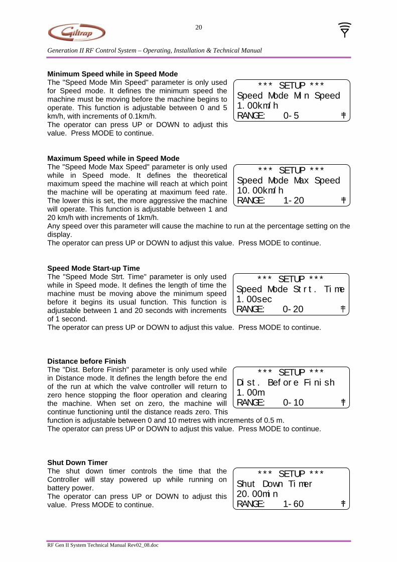
Minimum Speed while in Speed Mode The "Speed Mode Min Speed" parameter is only used for Speed mode. It defines the minimum speed the machine must be moving before the machine begins to operate. This function is adjustable between 0 and 5 km/h, with increments of 0.1km/h.
*** SETUP ***
Speed Mode Min Speed
1.00km/h
RANGE: 0-5 The operator can press UP or DOWN to adjust this value. Press MODE to continue. Maximum Speed while in Speed Mode The "Speed Mode Max Speed" parameter is only used while in Speed mode. It defines the theoretical maximum speed the machine will reach at which point the machine will be operating at maximum feed rate. The lower this is set, the more aggressive the machine will operate. This function is adjustable between 1 and 20 km/h with increments of 1km/h.
*** SETUP ***
Speed Mode Max Speed
10.00km/h
RANGE: 1-20
Any speed over this parameter will cause the machine to run at the percentage setting on the display. The operator can press UP or DOWN to adjust this value. Press MODE to continue. Speed Mode Start-up Time The "Speed Mode Strt. Time" parameter is only used while in Speed mode. It defines the length of time the machine must be moving above the minimum speed before it begins its usual function. This function is adjustable between 1 and 20 seconds with increments of 1 second.
*** SETUP ***
Speed Mode Strt. Time
1.00sec
RANGE: 0-20
The operator can press UP or DOWN to adjust this value. Press MODE to continue. Distance before Finish
*** SETUP ***
Dist. Before Finish
1.00m
RANGE: 0-10
The "Dist. Before Finish" parameter is only used while in Distance mode. It defines the length before the end of the run at which the valve controller will return to zero hence stopping the floor operation and clearing the machine. When set on zero, the machine will continue functioning until the distance reads zero. This function is adjustable between 0 and 10 metres with increments of 0.5 m. The operator can press UP or DOWN to adjust this value. Press MODE to continue. Shut Down Timer The shut down timer controls the time that the Controller will stay powered up while running on battery power.
*** SETUP ***
Shut Down Timer
20.00min
RANGE: 1-60 The operator can press UP or DOWN to adjust this value. Press MODE to continue.
RF Gen II System Technical Manual Rev02_08.doc

Generation II RF Control System – Operating, Installation & Technical Manual
21
Checking Setup Parameters A Function screen is available to check current settings. To enter, press and hold the left arrow for three or more seconds.
• The top line shows the requested valve position. • The second line shows the present gross load weight. • The third line shows the current machine ground speed. • The bottom line of the screen shows the current mode of operation (Std), the
Controller software revision and connectivity status. The Function mode screen is shown below: Requested valve position
Gross weight
Ground speed MODE:Std Rev 3.5
VALVE: 38%
GROSS: 2850kg
SPEED: 5.65km/h
Current operating mode Controller software revision
By pressing the UP or DOWN buttons, you can scroll and view parameters. They cannot be changed here. Press GO or STOP to exit and return to the operating screen.
RF Gen II System Technical Manual Rev02_08.doc

Generation II RF Control System – Operating, Installation & Technical Manual
22
Factory Parameter Settings Software Revision: Remote Display 3.4, Controller 3.8
To enter set-up, press TARE/GROSS and ZERO together for 4 seconds or until the set-up screen appears.
Press MODE until the correct parameter is displayed. Press UP or DOWN to adjust the parameter. Press STOP to exit the configuration screens. Remove power from the Controller to update changes.
Parameter Value Scale Damping Value 4.00 Load Cell Type 5000.00 kg Number Of Load Cells 4.00 Load Cell Sens. 2.00 mV/V (PT) or 2.20mV/V (Kelba) Scale Hysteresis 10.00 kg Scale Increments 10.00 kg Wheel Sensor Fitted Yes Wheel Diameter 760.00 mm No. of Wheel Holes 15.00 Low Batt Level 11.50 V Valve Fitted Yes Max Valve PSI 2250.00 psi Min Valve Setting 30.00 % Valve Ramp Up Time 0.00 sec Valve Ramp Down Time 0.00 sec Valve Startup Dist. 85.00 % Speed Mode Min Speed 1.00 km/h Speed Mode Max Speed 10.00 km/h Speed Mode Strt Time 1.00 sec Dist. Before Finish 1.00 m Shut Down Timer 20.00 min
Note: These are factory default settings. Some machines will require different settings.
RF Gen II System Technical Manual Rev02_08.doc

Generation II RF Control System – Operating, Installation & Technical Manual
23
Final Check Check that the Controller is working correctly: Plug in the 7-pin plug into the tractor and turn on the power switch. This applies power to the Controller. The POWER LED on the Controller should be illuminated. Unplug the 7-pin tractor plug. A battery power symbol ( ) will show on the screen which indicates the system is running on battery power and the wagon is not plugged into the tractor. After disconnecting the 7 pin plug and waiting 20 minutes (depending on parameter setting), the Controller should power down. If tractor power is reapplied, the Controller will restart. Note: To force power off and preserve battery power, press and hold the OFF button on the Controller when tractor power is disconnected. Check that the Power module is working correctly: When the wagon is plugged in the tractor, voltage should be higher than when unplugged. Plugged in should read approx 13.9 – 14.5V. Unplugged should read approx 11.5 – 12.8V. Check that there is RF communication: There should be an antenna symbol ( ) displayed in the bottom right hand side of the screen. Check that the valve (if fitted) is working correctly: Change the mode to Std, increase the ‘FEED RATE’ to 100% and press GO. The Controller LED will be illuminated when the valve reaches 100% setting and the valve solenoid will make a light buzzing noise. The wagon floor chain should start and stop when GO or STOP is pressed. System hydraulic pressure can sometimes cause the floor to not quite stop. In this case, increase tractor revs and recheck. Check that the load scales (if fitted) are weighing correctly: This can be done by applying a known load to the floor after zeroing. The Weight module LED labelled ‘Weight’ should be illuminated whenever the system is running. If the weight display is unstable when stationary, charging the battery will help. The voltage will be displayed on the lower line of the screen. When the system is running on battery power, a ( ) symbol will display alongside the voltage reading. Check that the wheel sensor (if fitted) is working correctly: Jack up the wheel with the wheel sensor fitted and check that the sensor light blinks for each hole while the wheel rotates. The green LED labelled PROX in the weight module should also blink at the same time as the sensor light. In distance mode, dial up a distance of say 20 metres on the Remote Display and press GO. Rotate the wheel 2-3 revolutions (forward or reverse) and check that the distance is decreasing. All complete: Ship with battery connected (it will power down to preserve power).
RF Gen II System Technical Manual Rev02_08.doc