Embed Size (px)
Citation preview
RF Channel Characterization with Multiple Antenna Systems
for LTE Leonhard Korowajczuk
CEO/CTO CelPlan Technologies
[email protected] www.celplan.com
703-259-4022
9/18/2012 Copyright CelPlan Technologies, Inc. 1

CelPlan Technologies • Planning, Design and Optimization Software for all
applications and network technologies
• Network planning, design an optimization services
• Turnkey deployment of dedicated wireless networks
• Specialized High Level Consulting
• Technical Team Building
• Technology Training
• Business Case Preparation
• CelPlan has design and optimized hundreds of networks of all main technologies around the world
9/18/2012 Copyright CelPlan Technologies, Inc. 2

Leonhard Korowajczuk • 45 years R&D, engineering and manufacturing experience in
the telecom field – SESA RIO, STC , BTM – CPqD (Telecom R&D Center) – Elebra/ Alcatel – CEO and CTO CelPlan Technologies – Holds 13 patents
• Published Books – “Designing cdma2000 Systems” published by Wiley in 2006- 963 pages, available in hard cover, e-book and
Kindle – “LTE , WiMAX and WLAN Network Design, Optimization and
Performance Analysis ” published by Wiley (June 2011)- 750 pages, available in hard cover, e-
book and Kindle
• Books in Preparation: – LTE , WiMAX and WLAN Network Design, Optimization and
Performance Analysis- second edition (Wiley) – Network Video: Private and Public Safety Applications (Wiley) – Multi-technology Networks: from GSM to LTE (Wiley) – Backhaul Network Design (Wiley) – Smart Grids Network Design
9/18/2012 Copyright CelPlan Technologies, Inc. 3
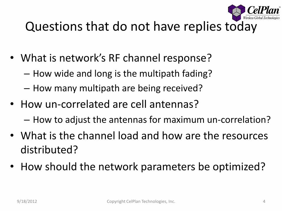
Questions that do not have replies today
• What is network’s RF channel response?
– How wide and long is the multipath fading?
– How many multipath are being received?
• How un-correlated are cell antennas?
– How to adjust the antennas for maximum un-correlation?
• What is the channel load and how are the resources distributed?
• How should the network parameters be optimized?
9/18/2012 Copyright CelPlan Technologies, Inc. 4

CelSDRx™ • Universal Software Defined Receiver (SDRx) • Captures up to 100 MHz of spectrum from 100 MHz to 18 GHz • Digitizes signal at 125 Msps and provides I and Q components • Digitally extracts information for any digital technology: LTE, WiMAX, HSPA, UMTS,
GSM • Implemented for LTE
– Performs • Symbol synchronization • Frame Synchronization • Sub-Channel Equalization • Bandwidth and frame number determination
– Detects • RF Channel Response in time and frequency
– Displays fading amplitude, band and duration
• Channel Traffic load • Received signal coherence from different antennas • Received signal coherence to different antennas
• GPS data geo-referencing, allowing drive tests • Ideal to plan network parameters • Ideal to scan competitive networks • Patents applied
9/18/2012 Copyright CelPlan Technologies, Inc. 5

CelSDRx ™ Specifications • Frequency coverage: 100 MHz to 18 GHz • Instantaneous Bandwidth: 100 MHz • Displayed Average Noise Level:
• -115 dBm @ 10 MHz • -110 dBm @ 1500 MHz • -110 dBm @ 2500 MHz
• Maximum RF input: +10 dBm • Non-input related spurs: < -100 dBm • Maximum RF gain: 20 dB • IF gain: -10 to +30 dB in 1 dB steps • Power Supply +12 VDC
9/18/2012 Copyright CelPlan Technologies, Inc. 6

• Subcarrier spacing: 15 kHz • Frame Duration: 10 ms • Sub-Frame duration: 1ms • Slot Duration: 0.5 ms • Slot: 6 or 7 Symbols
9/18/2012 Copyright CelPlan Technologies, Inc. 7
LTE Downlink Frame

LTE Downlink Frame Detail • PSS (Primary Synchronization Signal)
• SSS (secondary Synchronization Signal)
• PBCH (Physical Broadcast Channel
• RS (Reference Signals)
• Control Channels
• Data Channels
• Resource Element
9/18/2012 Copyright CelPlan Technologies, Inc. 8

Reference Signals
• Each antenna transmits its own reference signals (RS)
• An antenna does not transmit in the slots dedicated to the other antenna symbols
• The exact position of the RS for an antenna depends on the CellID
9/18/2012 Copyright CelPlan Technologies, Inc. 9
12 sub-carriers
Normal CPExtended CP
Eve
n S
lot (0
.5 m
s)
2 S
lots
(1
ms)
Od
d S
lot (0
.5 m
s)
Antenna Port 0
Antenna Port 1
Antenna Port 2
Antenna Port 3
Symbol
12 sub-carriers

Resource Element and Resource Block • A Resource Element (RE) is defined by one sub-carrier and 1 symbol • A Resource Block (RB) is defined by 12 consecutive sub-carriers and 1 slot
duration • Short Cyclic Prefix: 12 sub-carriers x 7 symbols: 84 RE • Long Cyclic Prefix: 12 sub-carriers x 6 symbols: 72 RE • The smallest allocation for data transmission is one TTI (Transmission Time
Interval): 1 ms (1 sub-frame/ 2 slots/2 RB) • Several RE are reserved for Reference Signals and Control Channels
12 sub-carriers
7 s
ym
bo
ls
0.5 ms
1 slot6
sym
bo
ls
12 sub-carriers
0.5 ms
1 slot
9/18/2012 Copyright CelPlan Technologies, Inc. 10

LTE Measurement Capabilities • Bandwidth: 1.4 – 20 MHz • FDD and TDD • Measurements
– PSS Power/ Quality – SSS Power/Quality – Physical Layer Cell Identity Group – MIB detection (Bandwidth and Number of Antennas) – Reference Signal Received Power/Quality (RSRP) – Wideband Spectral Display with Marker Functions – Power vs. Time vs. Frequency – Average RSSI – Channel Impulse Response and Power Delay Profile – Number of Multipath Components – RF Channels Response – Antenna Correlation
• Measurements are time stamped and Geo-referenced
9/18/2012 Copyright CelPlan Technologies, Inc. 11
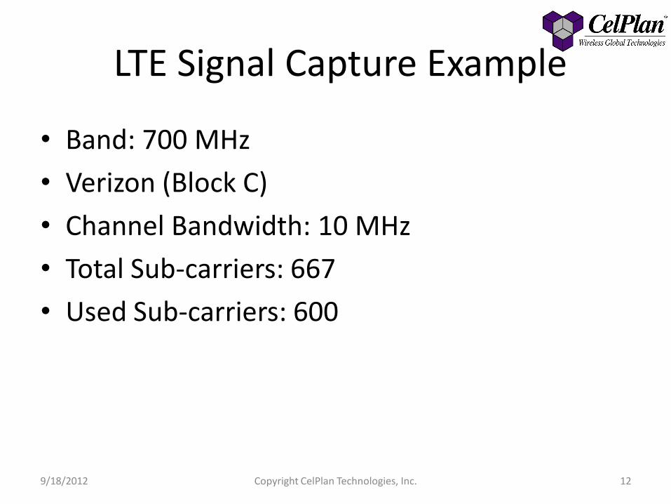
LTE Signal Capture Example
• Band: 700 MHz
• Verizon (Block C)
• Channel Bandwidth: 10 MHz
• Total Sub-carriers: 667
• Used Sub-carriers: 600
9/18/2012 Copyright CelPlan Technologies, Inc. 12

Steps • Set frequency and
capture bandwidth • Capture 200 ms • Extract baseband signal
I and Q • Apply FFT • Search for PSS
– Establish part of cell ID
• Search for SSS – Establish Cell ID – Synchronize frame
start and symbols
• Generate RS • Detect RS
9/18/2012 Copyright CelPlan Technologies, Inc. 13
• Obtain RF channel response
• Calculate RF channel response for RS signals
• Interpolate RF channel response for other symbols
• Adjust all symbol values
• Extract PBCH values
– MIB
– Channel bandwidth, number of antennas, cyclic prefix
– Frame number
• Obtain frame map
• Correlate frames

9/18/2012 Copyright CelPlan Technologies, Inc. 14
Average Sub-carrier Power per Frame (dBm)

9/18/2012 Copyright CelPlan Technologies, Inc. 15
Average OFDM Symbol Power per Band (dBm)
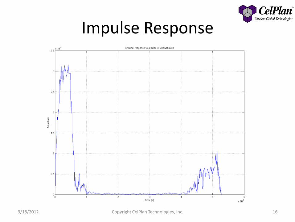
Impulse Response
9/18/2012 Copyright CelPlan Technologies, Inc. 16

Measured Power per Resource Element (dBm)
9/18/2012 Copyright CelPlan Technologies, Inc. 17

RF Channel Response (top view)
9/18/2012 Copyright CelPlan Technologies, Inc. 18

RF Channel Response (time zoom)
9/18/2012 Copyright CelPlan Technologies, Inc. 19

RF Channel Response (frequency and time zoom)
9/18/2012 Copyright CelPlan Technologies, Inc. 20

RF Channel Response (3D detail)
9/18/2012 Copyright CelPlan Technologies, Inc. 21
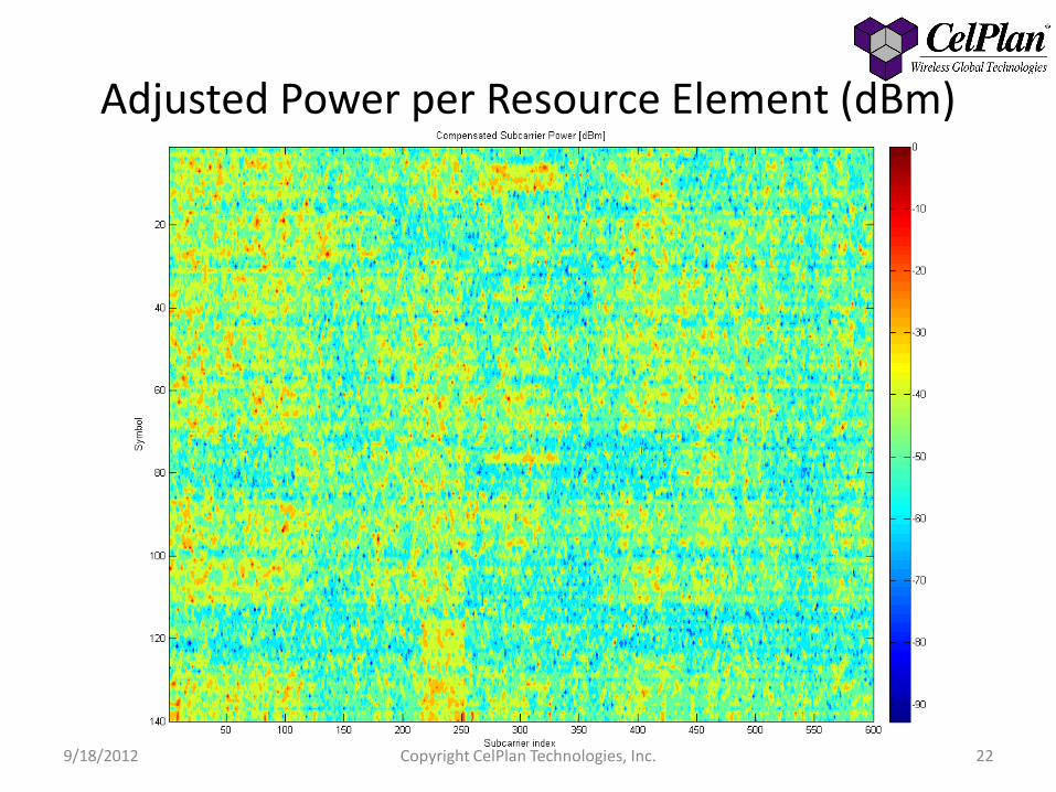
Adjusted Power per Resource Element (dBm)
9/18/2012 Copyright CelPlan Technologies, Inc. 22

Traffic view • Traffic allocation can be visualized per frame
9/18/2012 Copyright CelPlan Technologies, Inc. 23

Correlation • Correlation is considered as the sympathetic movement of two or
more variables • Pearson’s Product-Moment Correlation Coefficient
– The correlation coefficient varies between +1 and -1 • Positive Correlation: movement is in the same direction • Negative Correlation: movement is in the opposite direction
• Reference signals transmitted by two antennas can be used to establish the channel response
• The correlation coefficient for the two channel responses can then be calculated
9/18/2012 Copyright CelPlan Technologies, Inc. 24

Correlation between antennas • Correlation index between two antennas
CI=0.42
9/18/2012 Copyright CelPlan Technologies, Inc. 25

Antenna Correlation Drive • Antenna correlation variation
9/18/2012 Copyright CelPlan Technologies, Inc. 26

Conclusion
• CelSDRx ™ promises to be an important tool to evaluate the RF channel performance and tune systems with multiple antennas. – It will increase network throughput and reduce
interference
• A side benefit is the ability of evaluating traffic loads
• The flexibility of Software Defined Receivers is essential for the complex digital systems being deployed
9/18/2012 Copyright CelPlan Technologies, Inc. 27