Embed Size (px)
Citation preview
Rexroth Frequency Converter
The Drive & Control Company
Fv Series
Edition 05Quick Start GuideR912004885

Bosch Rexroth AG
Record of Revision
Edition Release Date NotesDOK-RCON02-FV*********-IN02-EN-P 2014.02 First release
DOK-RCON02-FV*********-IN03-EN-P 2014.07Added encoder adapt-er information
DOK-RCON02-FV*********-IN04-EN-P 2014.11 Added new functionsDOK-RCON02-FV*********-IN05-EN-P 2015.05 Added new functions
About this Documentation
This Instruction Manual (Quick Start) is derived from the Instruction Manualwhich includes the product data in details.Never work with or control the product before reading through the Safety In-structions in the standard delivery and the safety related chapter in the Instruc-tion Manual.
Reference
For documentation available in other type or language, please consult your localsales partner or check www.boschrexroth.com/fv.
Copyright
© Bosch Rexroth (Xi'an) Electric Drives and Controls Co., Ltd. 2015This document, as well as the data, specifications and other information setforth in it, are the exclusive property of Bosch Rexroth (Xi'an) Electric Drivesand Controls Co., Ltd. It may not be reproduced or given to third parties withoutits consent.
Liability
The specified data is intended for product description purposes only and shallnot be deemed to be a guaranteed characteristic unless expressly stipulated inthe contract. All rights are reserved with respect to the content of this documen-tation and the availability of the product.
RS-04650518eab9641b0a6846a50052ba5d-4-en-US-6

Table of ContentsPage
1 Mechanical Installation.......................................................................... 11.1 Visual Check.......................................................................................... 11.2 Ambient Conditions............................................................................... 11.3 Installation Conditions........................................................................... 21.4 Dimensions............................................................................................ 3
2 Electric Installation................................................................................ 72.1 Cable Specifications.............................................................................. 72.2 Power Terminals.................................................................................. 122.3 Interface Connection for Signals......................................................... 13
3 Parameter Settings.............................................................................. 233.1 Operating Panel................................................................................... 233.2 Start-up................................................................................................ 233.3 Operating Descriptions........................................................................ 253.4 Parameters........................................................................................... 26
4 Fault Indication.................................................................................... 32
Bosch Rexroth AGTable of Contents
DOK-RCON02-FV*********-IN05-EN-P I

Bosch Rexroth AG
II DOK-RCON02-FV*********-IN05-EN-P
1 Mechanical Installation
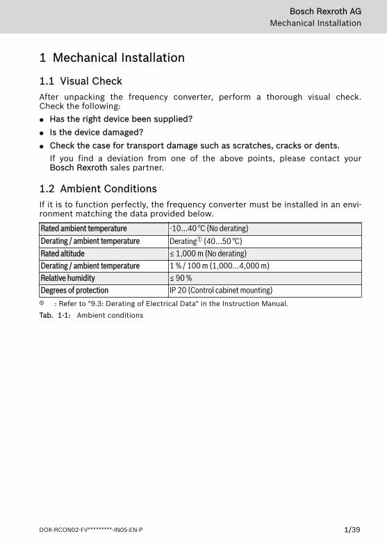
1.1 Visual CheckAfter unpacking the frequency converter, perform a thorough visual check.Check the following:● Has the right device been supplied?● Is the device damaged?● Check the case for transport damage such as scratches, cracks or dents.
If you find a deviation from one of the above points, please contact yourBosch Rexroth sales partner.
1.2 Ambient ConditionsIf it is to function perfectly, the frequency converter must be installed in an envi-ronment matching the data provided below.
Rated ambient temperature -10...40 °C (No derating)Derating / ambient temperature Derating① (40...50 °C)Rated altitude ≤ 1,000 m (No derating)Derating / ambient temperature 1 % / 100 m (1,000...4,000 m)Relative humidity ≤ 90 %Degrees of protection IP 20 (Control cabinet mounting)① : Refer to "9.3: Derating of Electrical Data" in the Instruction Manual.Tab. 1-1: Ambient conditions
Bosch Rexroth AGMechanical Installation
DOK-RCON02-FV*********-IN05-EN-P 1/39

1.3 Installation ConditionsDepending on rating, the frequency converters are available in different sizes. Inorder not to affect device cooling, the frequency converter must always be in-stalled upright. For perfect heat dissipation, the minimum installation spacingabove and below the devices shown in the drawing must be observed.
Fig. 1-1: Installation conditions
● The frequency converter shown above is Frame 1. The minimuminstallation spacing stated applies to Frame 1 to Frame 7.
● Frequency Converter Fv has no side ventilation hole, which ena-bles parallel mounting of Fv with zero distance.
● If one frequency converter is arranged above another, make surethe upper limit of air temperature into the inlet is not exceeded(see chapter 1.2 "Ambient Conditions" on page 1). A baffle plateis recommended between the frequency converters to prevent therising hot air being drawn into the upper converter if the upperlimit of air temperature is exceeded.
Bosch Rexroth AGMechanical Installation
2/39 DOK-RCON02-FV*********-IN05-EN-P
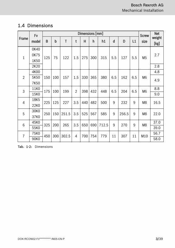
1.4 Dimensions
FrameFv
model
Dimensions [mm] Screwsize
Netweight
[kg]B b T t H h h1 d D L1
1
0K400K751K50
125 75 122 1.5 275 300 315 5.5 127 5.5 M52.7
2K20 2.8
24K00
150 100 157 1.5 330 365 380 6.5 162 6.5 M64.8
5K507K50
4.9
311K0
175 100 199 2 398 432 448 6.5 204 6.5 M68.8
15K0 9.0
418K522K0
225 125 227 3.5 440 482 500 9 232 9 M8 16.5
530K037K0
250 150 251.5 3.5 525 567 585 9 256.5 9 M8 22.0
645K0
325 200 265 3.5 650 690 712.5 9 270 9 M837.0
55K0 39.0
775K0
450 300 302.5 4 700 754 779 11 307 11 M1056.7
90K0 58.0
Tab. 1-2: Dimensions
Bosch Rexroth AGMechanical Installation
DOK-RCON02-FV*********-IN05-EN-P 3/39
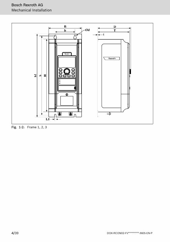
Fig. 1-2: Frame 1, 2, 3
Bosch Rexroth AGMechanical Installation
4/39 DOK-RCON02-FV*********-IN05-EN-P
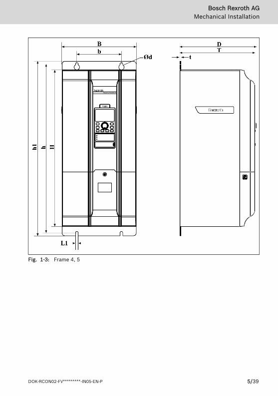
Fig. 1-3: Frame 4, 5
Bosch Rexroth AGMechanical Installation
DOK-RCON02-FV*********-IN05-EN-P 5/39

Fig. 1-4: Frame 6, 7
Bosch Rexroth AGMechanical Installation
6/39 DOK-RCON02-FV*********-IN05-EN-P
2 Electric Installation
2.1 Cable Specifications
2.1.1 Connecting to the Mains
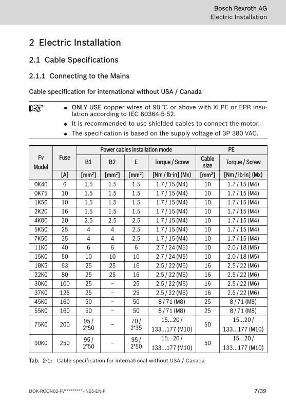
Cable specification for international without USA / Canada
● ONLY USE copper wires of 90 ℃ or above with XLPE or EPR insu-lation according to IEC 60364-5-52.
● It is recommended to use shielded cables to connect the motor.● The specification is based on the supply voltage of 3P 380 VAC.
FvModel
FusePower cables installation mode PE
B1 B2 E Torque / Screw Cablesize Torque / Screw
[A] [mm2] [mm2] [mm2] [Nm / lb-in] (Mx) [mm2] [Nm / lb-in] (Mx)0K40 6 1.5 1.5 1.5 1.7 / 15 (M4) 10 1.7 / 15 (M4)0K75 10 1.5 1.5 1.5 1.7 / 15 (M4) 10 1.7 / 15 (M4)1K50 10 1.5 1.5 1.5 1.7 / 15 (M4) 10 1.7 / 15 (M4)2K20 16 1.5 1.5 1.5 1.7 / 15 (M4) 10 1.7 / 15 (M4)4K00 20 2.5 2.5 2.5 1.7 / 15 (M4) 10 1.7 / 15 (M4)5K50 25 4 4 2.5 1.7 / 15 (M4) 10 1.7 / 15 (M4)7K50 25 4 4 2.5 1.7 / 15 (M4) 10 1.7 / 15 (M4)11K0 40 6 6 6 2.7 / 24 (M5) 10 2.0 / 18 (M5)15K0 50 10 10 10 2.7 / 24 (M5) 10 2.0 / 18 (M5)18K5 63 25 25 16 2.5 / 22 (M6) 16 2.5 / 22 (M6)22K0 80 25 25 16 2.5 / 22 (M6) 16 2.5 / 22 (M6)30K0 100 25 – 25 2.5 / 22 (M6) 16 2.5 / 22 (M6)37K0 125 25 – 25 2.5 / 22 (M6) 16 2.5 / 22 (M6)45K0 160 50 – 50 8 / 71 (M8) 25 8 / 71 (M8)55K0 160 50 – 50 8 / 71 (M8) 25 8 / 71 (M8)
75K0 200 95 /2*50 – 70 /
2*3515...20 /
133...177 (M10)50
15...20 /133...177 (M10)
90K0 250 95 /2*50 – 95 /
2*5015...20 /
133...177 (M10)50
15...20 /133...177 (M10)
Tab. 2-1: Cable specification for international without USA / Canada
Bosch Rexroth AGElectric Installation
DOK-RCON02-FV*********-IN05-EN-P 7/39

"–" indicates using cables of 105 ℃ or above with the same dimen-sions as those of installation mode B1.
Bosch Rexroth AGElectric Installation
8/39 DOK-RCON02-FV*********-IN05-EN-P
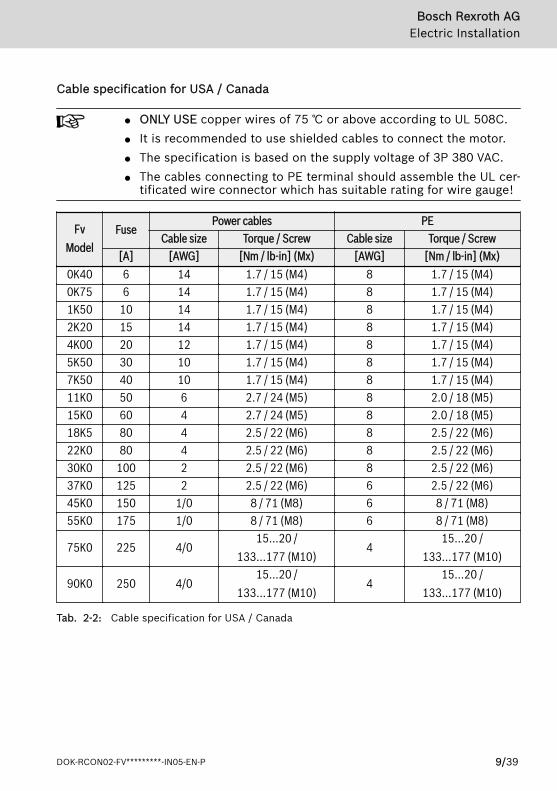
Cable specification for USA / Canada
● ONLY USE copper wires of 75 ℃ or above according to UL 508C.● It is recommended to use shielded cables to connect the motor.● The specification is based on the supply voltage of 3P 380 VAC.● The cables connecting to PE terminal should assemble the UL cer-
tificated wire connector which has suitable rating for wire gauge!
FvModel
FusePower cables PE
Cable size Torque / Screw Cable size Torque / Screw[A] [AWG] [Nm / lb-in] (Mx) [AWG] [Nm / lb-in] (Mx)
0K40 6 14 1.7 / 15 (M4) 8 1.7 / 15 (M4)0K75 6 14 1.7 / 15 (M4) 8 1.7 / 15 (M4)1K50 10 14 1.7 / 15 (M4) 8 1.7 / 15 (M4)2K20 15 14 1.7 / 15 (M4) 8 1.7 / 15 (M4)4K00 20 12 1.7 / 15 (M4) 8 1.7 / 15 (M4)5K50 30 10 1.7 / 15 (M4) 8 1.7 / 15 (M4)7K50 40 10 1.7 / 15 (M4) 8 1.7 / 15 (M4)11K0 50 6 2.7 / 24 (M5) 8 2.0 / 18 (M5)15K0 60 4 2.7 / 24 (M5) 8 2.0 / 18 (M5)18K5 80 4 2.5 / 22 (M6) 8 2.5 / 22 (M6)22K0 80 4 2.5 / 22 (M6) 8 2.5 / 22 (M6)30K0 100 2 2.5 / 22 (M6) 8 2.5 / 22 (M6)37K0 125 2 2.5 / 22 (M6) 6 2.5 / 22 (M6)45K0 150 1/0 8 / 71 (M8) 6 8 / 71 (M8)55K0 175 1/0 8 / 71 (M8) 6 8 / 71 (M8)
75K0 225 4/015...20 /
133...177 (M10)4
15...20 /133...177 (M10)
90K0 250 4/015...20 /
133...177 (M10)4
15...20 /133...177 (M10)
Tab. 2-2: Cable specification for USA / Canada
Bosch Rexroth AGElectric Installation
DOK-RCON02-FV*********-IN05-EN-P 9/39

2.1.2 Signal ConnectionThe following requirements apply for the signal connection wiring:● flexible cables with wire end sleeves● cable cross-section: 0.3...0.75 mm2
● cable length: max. 20 m● analog inputs ±10 V, VR1, VR2, VR3, +I and GND: use shielded cables● analog inputs +I and GND: to eliminate interference from external influences,
connect +I and GND on the transducer with a 22 nF capacitor (50 V) and runthe signal cable two or three times through a ferrite ring.
Bosch Rexroth AGElectric Installation
10/39 DOK-RCON02-FV*********-IN05-EN-P
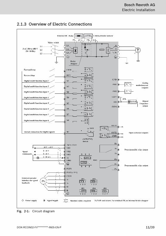
2.1.3 Overview of Electric Connections
Fig. 2-1: Circuit diagram
Bosch Rexroth AGElectric Installation
DOK-RCON02-FV*********-IN05-EN-P 11/39

2.2 Power TerminalsThe table below describes the symbols on the frequency converter's power con-nection terminals and their function.
Terminal DescriptionL1, L2, L3 Mains supply input terminalsU, V, W Frequency converter output terminalsPB External brake resistor terminal (Only applicable to 0K40...15K0 models)P1, (+) DC choke input or DC positive bus output terminal(-) DC negative bus output terminal
Grounding terminal
Tab. 2-3: Power terminals description
Depending on size, the position and order of the power terminals on the individ-ual frequency converter may differ. Refer to the graphics below for the exactconnection terminal position and sequence:
0K40...15K0
Fig. 2-2: Frame 1, 2, 3
18K5...90K0
Fig. 2-3: Frame 4, 5, 6, 7
Bosch Rexroth AGElectric Installation
12/39 DOK-RCON02-FV*********-IN05-EN-P

2.3 Interface Connection for Signals
2.3.1 Jumper Wiring
Fig. 2-4: Jumper description
Shown above are factory defaults.
2.3.2 NPN / PNP Jumper SW1
Fig. 2-5: NPN/PNP jumper SW1
The factory default for the jumper is NPN (Jumper contact at 1-3,4-6).
The jumper SW1 determines:1. The internal 24 V power supply or an external 24 V power supply is used
for the inputs.2. The inputs are activated by connection of 24 V to an input (PNP / active in-
put) or connection of 0 V to an input (NPN / passive input).Modes and signal inputs:The jumper SW1 can switch between 0 V (NPN / passive input) and +24 V (PNP /active input) inputs, respective external +24 V power supply is also available,which improves the flexibility of signal input mode.
Bosch Rexroth AGElectric Installation
DOK-RCON02-FV*********-IN05-EN-P 13/39
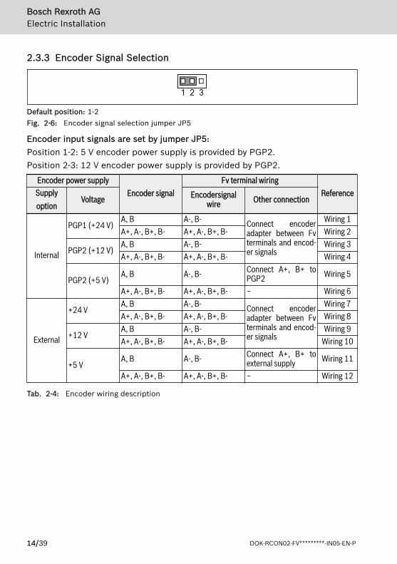
2.3.3 Encoder Signal Selection
Default position: 1-2Fig. 2-6: Encoder signal selection jumper JP5
Encoder input signals are set by jumper JP5:Position 1-2: 5 V encoder power supply is provided by PGP2.Position 2-3: 12 V encoder power supply is provided by PGP2.
Encoder power supplyEncoder signal
Fv terminal wiringReferenceSupply
optionVoltage Encodersignal
wire Other connection
Internal
PGP1 (+24 V)A, B A-, B- Connect encoder
adapter between Fvterminals and encod-er signals
Wiring 1A+, A-, B+, B- A+, A-, B+, B- Wiring 2
PGP2 (+12 V)A, B A-, B- Wiring 3A+, A-, B+, B- A+, A-, B+, B- Wiring 4
PGP2 (+5 V)A, B A-, B- Connect A+, B+ to
PGP2 Wiring 5
A+, A-, B+, B- A+, A-, B+, B- − Wiring 6
External
+24 VA, B A-, B- Connect encoder
adapter between Fvterminals and encod-er signals
Wiring 7A+, A-, B+, B- A+, A-, B+, B- Wiring 8
+12 VA, B A-, B- Wiring 9A+, A-, B+, B- A+, A-, B+, B- Wiring 10
+5 VA, B A-, B- Connect A+, B+ to
external supply Wiring 11
A+, A-, B+, B- A+, A-, B+, B- − Wiring 12
Tab. 2-4: Encoder wiring description
Bosch Rexroth AGElectric Installation
14/39 DOK-RCON02-FV*********-IN05-EN-P
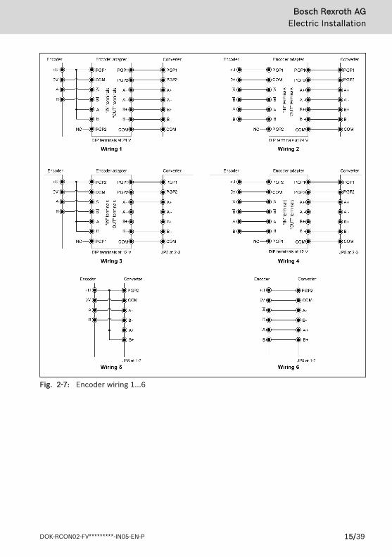
Fig. 2-7: Encoder wiring 1...6
Bosch Rexroth AGElectric Installation
DOK-RCON02-FV*********-IN05-EN-P 15/39
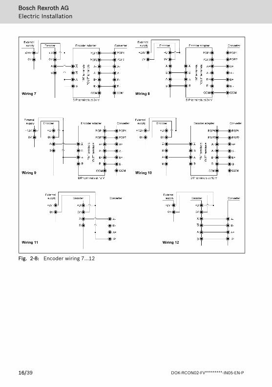
Fig. 2-8: Encoder wiring 7...12
Bosch Rexroth AGElectric Installation
16/39 DOK-RCON02-FV*********-IN05-EN-P

2.3.4 Encoder Adapter
The function of encoder adapter
The encoder adapter is used to improve the precision of speed sampling when+12 V or +24 V supply voltage is used for the encoder, no matter internal or ex-ternal supply.
Encoder adapter dimensions
Fig. 2-9: Encoder adapter dimensions
Bosch Rexroth AGElectric Installation
DOK-RCON02-FV*********-IN05-EN-P 17/39
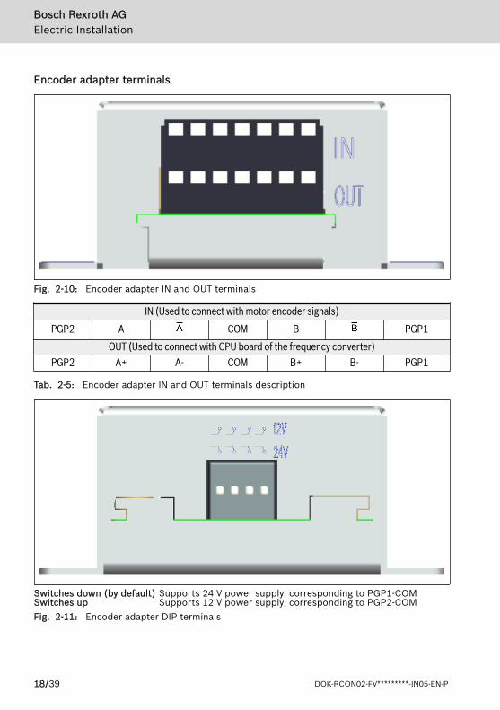
Encoder adapter terminals
Fig. 2-10: Encoder adapter IN and OUT terminals
IN (Used to connect with motor encoder signals)PGP2 A COM B PGP1
OUT (Used to connect with CPU board of the frequency converter)PGP2 A+ A- COM B+ B- PGP1
Tab. 2-5: Encoder adapter IN and OUT terminals description
Switches down (by default) Supports 24 V power supply, corresponding to PGP1-COMSwitches up Supports 12 V power supply, corresponding to PGP2-COMFig. 2-11: Encoder adapter DIP terminals
Bosch Rexroth AGElectric Installation
18/39 DOK-RCON02-FV*********-IN05-EN-P
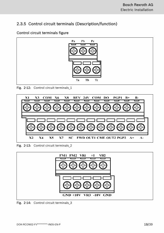
2.3.5 Control circuit terminals (Description/function)
Control circuit terminals figure
Fig. 2-12: Control circuit terminals_1
Fig. 2-13: Control circuit terminals_2
Fig. 2-14: Control circuit terminals_3
Bosch Rexroth AGElectric Installation
DOK-RCON02-FV*********-IN05-EN-P 19/39
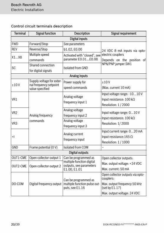
Control circuit terminals description
Terminal Signal function Description Signal requirementDigital inputs
FWD Forward/Stop See parametersb1.02, E0.00 24 VDC 8 mA inputs via opto-
electric couplersDepends on the position ofNPN/PNP jumper SW1
REV Reverse/Stop
X1...X8Multiple speedcommands
Activated with “closed”, seeparameter E0.01...E0.08
SCShared connectionfor digital signals
Isolated from GND
Analog inputs
±10 VSupply voltage for exter-nal frequency setpointvalue specified
Power supply forspeed commands
±10 V(Max. current 10 mA)
VR1
Analog frequencycommands
Analog voltagefrequency input 1
Input voltage range: -10...10 VInput resistance: 100 kΩResolution: 1 / 2000
VR2Analog voltagefrequency input 2
Input voltage range: 0...10 VInput resistance: 100 kΩResolution: 1/ 2000VR3
Analog voltagefrequency input 3
+IAnalog currentfrequency input
Input current range: 0...20 mAInput resistance:165 ΩResolution: 1 / 1000
GND Frame potential (0 V) Isolated from COM −Digital outputs
OUT1-CME Open collector output 1 Can be programmed asmultiple function digitaloutputs, see parametersE1.00, E1.01
Open collector outputs:Max. output voltage: +24 VDCMax. current: 50 mA
OUT2-CME Open collector output 2
DO-COM Digital frequency outputCan be programmed asmultiple function pulse out-puts, see E1.16
Open collector outputs via opto-couplers:Max. output frequency 50 kHz(set by E1.17)Max. output voltage: 24 VDC
Bosch Rexroth AGElectric Installation
20/39 DOK-RCON02-FV*********-IN05-EN-P
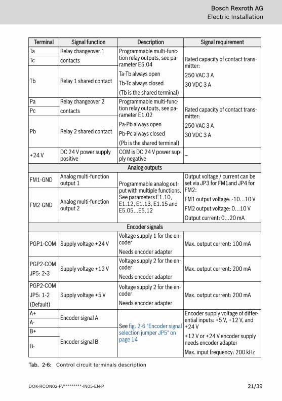
Terminal Signal function Description Signal requirementTa Relay changeover 1
contactsProgrammable multi-func-tion relay outputs, see pa-rameter E5.04Ta-Tb always openTb-Tc always closed(Tb is the shared terminal)
Rated capacity of contact trans-mitter:250 VAC 3 A30 VDC 3 A
Tc
Tb Relay 1 shared contact
Pa Relay changeover 2contacts
Programmable multi-func-tion relay outputs, see pa-rameter E1.02Pa-Pb always openPb-Pc always closed(Pb is the shared terminal)
Rated capacity of contact trans-mitter:250 VAC 3 A30 VDC 3 A
Pc
Pb Relay 2 shared contact
+24 V DC 24 V power supplypositive
COM is DC 24 V power sup-ply negative –
Analog outputs
FM1-GND Analog multi-functionoutput 1 Programmable analog out-
put with multiple functions.See parameters E1.10,E1.12, E1.13, E1.15 andE5.05...E5.12
Output voltage / current can beset via JP3 for FM1and JP4 forFM2:FM1 output voltage: -10...10 VFM2 output voltage: 0...10 VOutput current: 0...20 mA
FM2-GND Analog multi-functionoutput 2
Encoder signals
PGP1-COM Supply voltage +24 VVoltage supply 1 for the en-coderNeeds encoder adapter
Max. output current: 100 mA
PGP2-COMJP5: 2-3
Supply voltage +12 VVoltage supply 2 for the en-coderNeeds encoder adapter
Max. output current: 200 mA
PGP2-COMJP5: 1-2(Default)
Supply voltage +5 VVoltage supply 2 for the en-coderNeeds encoder adapter
Max. output current: 200 mA
A+Encoder signal A
See fig. 2-6 "Encoder signalselection jumper JP5" onpage 14
Encoder supply voltage of differ-ential inputs: +5 V, +12 V, and+24 V+12 V or +24 V encoder supplyneeds encoder adapterMax. input frequency: 200 kHz
A-B+
Encoder signal BB-
Tab. 2-6: Control circuit terminals description
Bosch Rexroth AGElectric Installation
DOK-RCON02-FV*********-IN05-EN-P 21/39

Before switching on the frequency converter, the removed contact covers andcase front have to be refitted.
Bosch Rexroth AGElectric Installation
22/39 DOK-RCON02-FV*********-IN05-EN-P
3 Parameter Settings
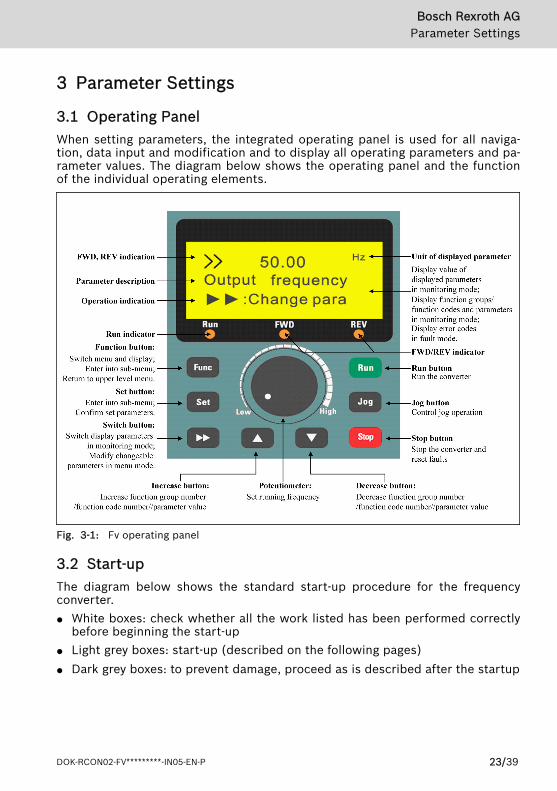
3.1 Operating PanelWhen setting parameters, the integrated operating panel is used for all naviga-tion, data input and modification and to display all operating parameters and pa-rameter values. The diagram below shows the operating panel and the functionof the individual operating elements.
Fig. 3-1: Fv operating panel
3.2 Start-upThe diagram below shows the standard start-up procedure for the frequencyconverter.● White boxes: check whether all the work listed has been performed correctly
before beginning the start-up● Light grey boxes: start-up (described on the following pages)● Dark grey boxes: to prevent damage, proceed as is described after the startup
Bosch Rexroth AGParameter Settings
DOK-RCON02-FV*********-IN05-EN-P 23/39
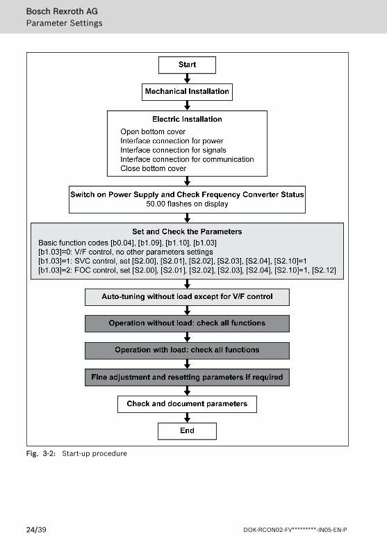
Fig. 3-2: Start-up procedure
Bosch Rexroth AGParameter Settings
24/39 DOK-RCON02-FV*********-IN05-EN-P

3.3 Operating Descriptions
Fig. 3-3: Operation mode description
Fig. 3-4: Example of operating panel operation
Bosch Rexroth AGParameter Settings
DOK-RCON02-FV*********-IN05-EN-P 25/39
3.4 Parameters
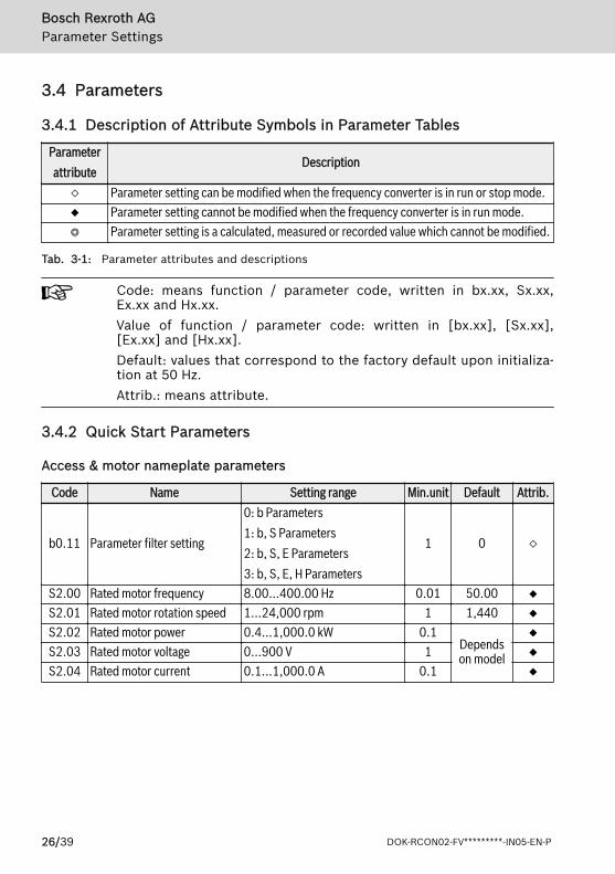
3.4.1 Description of Attribute Symbols in Parameter Tables
Parameterattribute
Description
◇ Parameter setting can be modified when the frequency converter is in run or stop mode.◆ Parameter setting cannot be modified when the frequency converter is in run mode.◎ Parameter setting is a calculated, measured or recorded value which cannot be modified.
Tab. 3-1: Parameter attributes and descriptions
Code: means function / parameter code, written in bx.xx, Sx.xx,Ex.xx and Hx.xx.Value of function / parameter code: written in [bx.xx], [Sx.xx],[Ex.xx] and [Hx.xx].Default: values that correspond to the factory default upon initializa-tion at 50 Hz.Attrib.: means attribute.
3.4.2 Quick Start Parameters
Access & motor nameplate parameters
Code Name Setting range Min.unit Default Attrib.
b0.11 Parameter filter setting
0: b Parameters1: b, S Parameters2: b, S, E Parameters3: b, S, E, H Parameters
1 0 ◇
S2.00 Rated motor frequency 8.00...400.00 Hz 0.01 50.00 ◆S2.01 Rated motor rotation speed 1...24,000 rpm 1 1,440 ◆S2.02 Rated motor power 0.4...1,000.0 kW 0.1
Dependson model
◆S2.03 Rated motor voltage 0...900 V 1 ◆S2.04 Rated motor current 0.1...1,000.0 A 0.1 ◆
Bosch Rexroth AGParameter Settings
26/39 DOK-RCON02-FV*********-IN05-EN-P
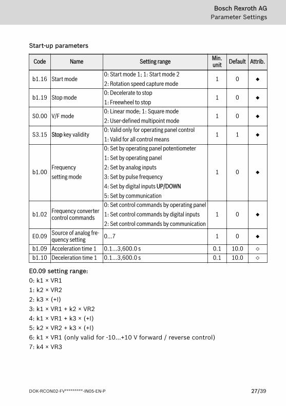
Start-up parameters
Code Name Setting range Min.unit Default Attrib.
b1.16 Start mode0: Start mode 1; 1: Start mode 22: Rotation speed capture mode
1 0 ◆
b1.19 Stop mode0: Decelerate to stop1: Freewheel to stop
1 0 ◆
S0.00 V/F mode0: Linear mode; 1: Square mode2: User-defined multipoint mode
1 0 ◆
S3.15 Stop key validity0: Valid only for operating panel control1: Valid for all control means
1 1 ◆
b1.00Frequencysetting mode
0: Set by operating panel potentiometer1: Set by operating panel2: Set by analog inputs3: Set by pulse frequency4: Set by digital inputs UP/DOWN5: Set by communication
1 0 ◆
b1.02 Frequency convertercontrol commands
0: Set control commands by operating panel1: Set control commands by digital inputs2: Set control commands by communication
1 0 ◆
E0.09 Source of analog fre-quency setting 0...7 1 0 ◆
b1.09 Acceleration time 1 0.1...3,600.0 s 0.1 10.0 ◇b1.10 Deceleration time 1 0.1...3,600.0 s 0.1 10.0 ◇
E0.09 setting range:0: k1 × VR11: k2 × VR22: k3 × (+I)3: k1 × VR1 + k2 × VR24: k1 × VR1 + k3 × (+I)5: k2 × VR2 + k3 × (+I)6: k1 × VR1 (only valid for -10...+10 V forward / reverse control)7: k4 × VR3
Bosch Rexroth AGParameter Settings
DOK-RCON02-FV*********-IN05-EN-P 27/39

Input / Output terminal functions
Code Name Setting range Min.unit Default Attrib.
E0.01...
E0.08
Digital input X1...Digital input X8
0...29 1 0 ◆
E1.00 Open collector output OUT10...14
1 1 ◆E1.01 Open collector output OUT2 1 1 ◆E1.02 Relay outputs Pa, Pb and Pc 1 1 ◆
E1.10 FM1 analog output
0: Output frequency/ rotation speed1: Set frequency/ rotation speed2: Output current3: Torque current4: Output voltage5: Output frequency / rotationspeed (including direction)6: Set frequency / rotationspeed (including direction)7: Communication setting
1 0 ◇
E1.11 FM1 negative gain setting 0.00...10.00 0.01 1.00 ◇E1.12 FM1 positive gain setting 0.00...10.00 0.01 1.00 ◇
E1.13 FM2 analog output
0: Output frequency/ rotation speed1: Set frequency/ rotation speed2: Output current3: Torque current4: Output voltage5: Communication setting
1 1 ◇
E1.15 FM2 gain setting 0.00...10.00 0.01 1.00 ◇
Bosch Rexroth AGParameter Settings
28/39 DOK-RCON02-FV*********-IN05-EN-P

Code Name Setting range Min.unit Default Attrib.
E1.16 Pulse outputs
0: Output frequency1: Output voltage2: Output current3: Encoder pulse
1 0 ◇
E1.17Maximum outputpulse frequency
1.0...50.0 kHz 0.1 10.0 ◇
E0.01...E0.08 setting range:0: Inactive (allows multiple selection)1: Multi-speed control 12: Multi-speed control 23: Multi-speed control 34: Multi-speed control 45: Acceleration/deceleration time 16: Acceleration/deceleration time 27: 3-wire control8: Freewheel to stop9: Frequency increment UP10: Frequency decrement DOWN11: Set frequency to 012: Reserved13: Activate shutdown DC brake14: Switch between operating panel and digital inputs control15: Logic control deactivated16: Logic control paused17: Switch between speed and torque control18: Switch between VR1 analog reference and +I analog reference19: External fault N.O. contact input20: External fault N.C. contact input21: External Reset input22: Activate communication control23: Torque limit set by VR1 enabled24: Torque limit set by VR2 enabled25: Forward jogging
Bosch Rexroth AGParameter Settings
DOK-RCON02-FV*********-IN05-EN-P 29/39

26: Reverse jogging27: Process PID deactivated28: Speed limit set by VR1 enabled29: Speed limit set by VR2 enabled
E1.00...E1.02 setting range:0: Frequency converter is ready to run1: Frequency converter is running2: DC brake active3: Frequency converter runs at zero speed4. Frequency/speed arrival signal5. Frequency level detection signal (FDT1)6. Frequency level detection signal (FDT2)7: Logic control phase completed8: 8: Under voltage stop9: Frequency converter over load pre-warning 110: Motor over load pre-warning11: Over torque12: Frequency converter in fault13: Fault auto reset signal output14: Frequency converter over load pre-warning 2
Bosch Rexroth AGParameter Settings
30/39 DOK-RCON02-FV*********-IN05-EN-P

Fault message and diagnosis
Code Name Setting range Min.unit Default Attrib.E4.13 Last fault
0...261 0 ◎
E4.14 2nd last fault 1 0 ◎E4.15 3rd last fault 1 0 ◎
E4.16 Delete fault record
0: Inactive1: Delete fault recordNote: The value is automatically set to 0after the operation.
1 0 ◆
b0.02 Restore factory default
0: No action1: Restore parameter to factory defaultNote: The value is automatically set to 0after restoring factory default.
1 0 ◆
E4.13...E4.15 setting range:0: No fault record1: Over current at constant speed (O.C.-1)2: Over current during acceleration (O.C.-2)3: Over current during deceleration (O.C.-3)4: Over voltage at constant speed (O.E.-1)5: Over voltage during acceleration (O.E.-2)6: Over voltage during deceleration (O.E.-3)7: Frequency converter over load (O.L.-1)8: Motor over load (O.L.-2); 9: CPU read/write fault (R.E.)10: Operating panel read/write fault (KEY-)11: External device fault (E.-St)12: Communication fault (R.S.)13: Circuit disconnection (C.F.)14: Pulse encoder speed detection fault (PULS)15: Motor overheat (M.O.H.); 16: EMI fault (CPU-)17: Short circuit (S.C.) ;18: Reserved19: L1, L2, L3 input phase loss (IPH.L)20: U, V, W output phase loss (OPH.L)21: Frequency converter overheat (C.O.H.)22: Parameter setting fault (PRSE); 23: Parameter auto-tuning fault (TUNE)24: Frequency converter over load pre-warning 2 (O.L.-3)25: Broken wire alarm (B.W.A); 26: Broken wire fault (B.W.F)
Bosch Rexroth AGParameter Settings
DOK-RCON02-FV*********-IN05-EN-P 31/39

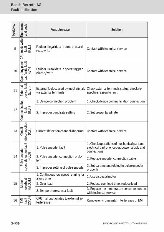
4 Fault Indication
Faul
t No.
Faul
t nam
ean
d co
de
Possible reason Solution
1
Over
curre
ntat
cons
tant
spee
d(O
.C.-1
)
1. Discontinuous or abnormal load inrun mode 1. Check load
2. Low mains voltage2. Check voltage of input power supply:3P 380...480 VAC (-15 % / +10 %)
3. Motor power and converter powerdo not match
3. Motor power has to match with converterpower
4. Too large inertia or load 4. Check motor power, converter power, load5. Pulse encoder fault 5. Check pulse encoder and its connection
2
Over
curre
ntdu
ring a
ccele
ratio
n(O
.C.-2
)
1. Too large start frequency 1. Reduce start frequency2. Too large load rotation inertia, toolarge impact load
2. Increase acceleration time, reduce suddenload change
3. Improper motor parameter setting 3. Set motor parameters properly or autotune motor parameters (group S2)
4. Direct start during motor running 4. Restart after motor stop, or start with rota-tion speed capture (group b1)
5. Too short acceleration time 5. Increase acceleration time6. Motor power and converter powerdo not match
6. Motor power has to match with converterpower
7. Pulse encoder fault 7. Check pulse encoder and its connection
8. Improper V/F curve 8. Adjust V/F curve setting and torque in-crease
3
Over
curre
ntdu
ring d
ecele
ratio
n(O
.C.-3
)
1. Improper motor parameter setting 1. Set motor parameters properly or autotune motor parameters (group S2)
2. Too large load rotation inertia 2. Use suitable brake components3. Too short deceleration time 3. Increase deceleration time4. Motor power and converter powerdo not match
4. Motor power has to match with converterpower
5. Pulse encoder fault 5. Check pulse encoder and its connection
4
Over
volta
geat
cons
tant
spee
d(O
.E.-1
)
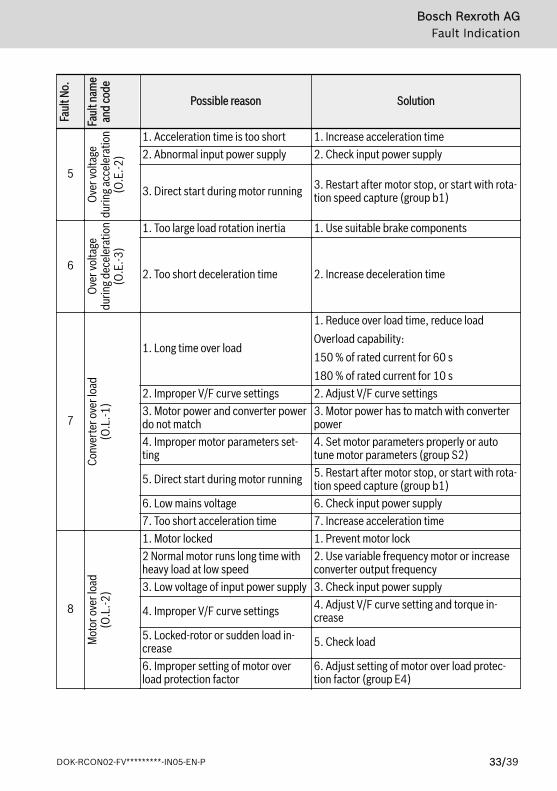
1. Acceleration / deceleration time istoo short 1. Increase acceleration/ deceleration time
2. Abnormal input power supply 2. Check input power supply3. Too much load change 3. Use suitable brake components4. Improper speed loop parametersetting in vector control
4. Adjust PI parameters of speed loop (groupS1)
Bosch Rexroth AGFault Indication
32/39 DOK-RCON02-FV*********-IN05-EN-P
Faul
t No.
Faul
t nam
ean
d co
dePossible reason Solution
5
Over
volta
gedu
ring a
ccele
ratio
n(O
.E.-2
)1. Acceleration time is too short 1. Increase acceleration time2. Abnormal input power supply 2. Check input power supply
3. Direct start during motor running 3. Restart after motor stop, or start with rota-tion speed capture (group b1)
6
Over
volta
gedu
ring d
ecele
ratio
n(O
.E.-3
)
1. Too large load rotation inertia 1. Use suitable brake components
2. Too short deceleration time 2. Increase deceleration time
7
Conv
erte
r ove
r loa
d(O
.L.-1
)
1. Long time over load
1. Reduce over load time, reduce loadOverload capability:150 % of rated current for 60 s180 % of rated current for 10 s
2. Improper V/F curve settings 2. Adjust V/F curve settings3. Motor power and converter powerdo not match
3. Motor power has to match with converterpower
4. Improper motor parameters set-ting
4. Set motor parameters properly or autotune motor parameters (group S2)
5. Direct start during motor running 5. Restart after motor stop, or start with rota-tion speed capture (group b1)
6. Low mains voltage 6. Check input power supply7. Too short acceleration time 7. Increase acceleration time
8
Mot
or ov
er lo
ad(O
.L.-2
)
1. Motor locked 1. Prevent motor lock2 Normal motor runs long time withheavy load at low speed
2. Use variable frequency motor or increaseconverter output frequency
3. Low voltage of input power supply 3. Check input power supply
4. Improper V/F curve settings 4. Adjust V/F curve setting and torque in-crease
5. Locked-rotor or sudden load in-crease 5. Check load
6. Improper setting of motor overload protection factor
6. Adjust setting of motor over load protec-tion factor (group E4)
Bosch Rexroth AGFault Indication
DOK-RCON02-FV*********-IN05-EN-P 33/39
Faul
t No.
Faul
t nam
ean
d co
dePossible reason Solution
9
CPU
read
/ writ
efa
ult
(R.E
.) Fault or illegal data in control boardread/write Contact with technical service
10
Oper
atin
g pan
elre
ad/w
rite f
ault
(KEY
-) Fault or illegal data in operating pan-el read/write Contact with technical service
11
Exte
rnal
devic
e fau
lt(E
.-St) External fault caused by input signals
via external terminalsCheck external terminals status, check re-spective reason to fault
12
Com
mun
icatio
nfa
ult
(R.S
.)
1. Device connection problem 1. Check device communication connection
2. Improper baud rate setting 2. Set proper baud rate
13
Circ
uit
disc
onne
ctio
n(C
.F.)
Current detection channel abnormal Contact with technical service
14
Pulse
enco
der
spee
d de
tect
ion f
ault
(PUL
S)
1. Pulse encoder fault1. Check operations of mechanical part andelectrical part of encoder, power supply andconnections
2. Pulse encoder connection prob-lem 2. Replace encoder connection cable
3. Improper setting of pulse encoder 3. Set parameters related to pulse encoderproperly
15
Mot
orov
erhe
at(M
.O.H
.)
1. Continuous low speed running fora long time 1. Use a special motor
2. Over load 2. Reduce over load time, reduce load
3. Temperature sensor fault 3. Replace the temperature sensor or contactwith technical service
16 EMI
faul
t(C
PU-) CPU malfunction due to external in-
terference Remove environmental interference or EMI
Bosch Rexroth AGFault Indication
34/39 DOK-RCON02-FV*********-IN05-EN-P

Faul
t No.
Faul
t nam
ean
d co
dePossible reason Solution
17
Shor
tcir
cuit
(S.C
.) 1. Too large output current 1. Check if motor short circuit, motor to earthshort circuit, over load exists
2. Power component fault 2. Contact with technical service18 Reserved
19
L1, L
2, L3
inpu
tph
ase l
oss
(IPH.
L)
1. Abnormal, omitted or broken con-nection of converter power supply
1. Follow operating procedures to checkpower supply connections, remove omittedor broken connections
2. Broken fuse 2. Check fuse3. Imbalance in the three phases ofinput power supply 3. Check installation wiring and input voltage
20
U, V,
W ou
tput
phas
e los
s(O
PH.L
) 1. Abnormal, omitted or broken con-nection of converter outputs
1. Check connections of frequency converteroutputs, remove omitted or broken connec-tions
2. Imbalance in the three phases ofoutputs 2. Check motor
21 Fvov
er he
at(C
.O.H
.) 1. Converter over heat1. Reduce ambient temperature, improveventilation and heat dissipation; clear dust,cotton wadding in air ducts; check fan and itspower supply connection
2. Temperature detection circuit fault 2. Contact with technical service
22
Para
met
erse
tting
faul
t(P
RSE)
Improper setting of parameters Check set values of parameters
23
Para
met
erau
to-tu
ning
faul
t(T
UNE)
1. Power of special or normal motordoes not match with converter pow-er
1. Check if the motor is special motor, checkif the motor power matches with converterpower
2. Improper setting of motor parame-ters
2. Set parameters according to motor name-plate
3. No connection of converter withmotor 3. Check motor cable connections
24
Freq
uenc
y con
verte
rov
er lo
adpr
e-wa
rnin
g 2
See descriptions of option 14 of pa-rameters E1.00...E1.02 Reduce over load time, reduce load
Bosch Rexroth AGFault Indication
DOK-RCON02-FV*********-IN05-EN-P 35/39
Faul
t No.
Faul
t nam
ean
d co
dePossible reason Solution
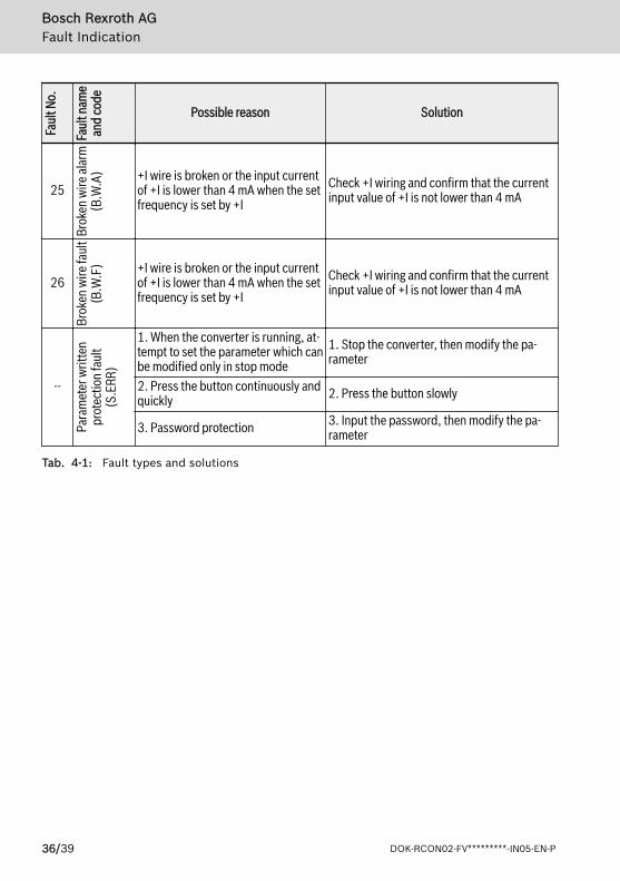
25
Brok
en w
ire al
arm
(B.W
.A) +I wire is broken or the input current
of +I is lower than 4 mA when the setfrequency is set by +I
Check +I wiring and confirm that the currentinput value of +I is not lower than 4 mA
26
Brok
en w
ire fa
ult
(B.W
.F) +I wire is broken or the input current
of +I is lower than 4 mA when the setfrequency is set by +I
Check +I wiring and confirm that the currentinput value of +I is not lower than 4 mA
--
Para
met
er w
ritte
npr
otec
tion f
ault
(S.E
RR)
1. When the converter is running, at-tempt to set the parameter which canbe modified only in stop mode
1. Stop the converter, then modify the pa-rameter
2. Press the button continuously andquickly 2. Press the button slowly
3. Password protection 3. Input the password, then modify the pa-rameter
Tab. 4-1: Fault types and solutions
Bosch Rexroth AGFault Indication
36/39 DOK-RCON02-FV*********-IN05-EN-P

Bosch Rexroth AG
DOK-RCON02-FV*********-IN05-EN-P 37/39

Bosch Rexroth AG
38/39 DOK-RCON02-FV*********-IN05-EN-P

Notes
Bosch Rexroth AG

The Drive & Control Company
Bosch Rexroth AG Electric Drives and Controls P.O. Box 13 57 97803 Lohr, Germany Bgm.-Dr.-Nebel-Str. 2 97816 Lohr, Germany Tel. +49 9352 40 5060 Fax +49 9352 18 4941 [email protected]
DOK-RCON02-FV*********-IN05-EN-P
R912004885


![A.N.S.V.S.A · 2018. 8. 9. · FV 13 Babesti FV 2 Bixad F V ] 2 Batarci FV 14 Halmeu FV 29 Dacia FV 36 Foieni FV 37 Sanislau FV 38 Piscolt . AV Silvatica AV Oas A VP Certcze A VPS](https://img.dokumen.tips/doc/110x75/5fd9f3aeec14dd3d7c54bb33/ansvsa-2018-8-9-fv-13-babesti-fv-2-bixad-f-v-2-batarci-fv-14-halmeu.jpg)