Embed Size (px)
Citation preview
RevoMaker: Enabling Multi-directional andFunctionally-embedded 3D Printing using a Rotational
Cuboidal Platform
Wei Gao⇤, Yunbo Zhang⇤, Diogo C. Nazzetta, Karthik Ramani, Raymond J. CipraSchool of Mechanical Engineering, Purdue University
West Lafayette, IN 47907{gao51, ybzhang, dn, ramani, cipra}@purdue.edu
ABSTRACTIn recent years, 3D printing has gained significant attentionfrom the maker community, academia, and industry to sup-port low-cost and iterative prototyping of designs. Currentunidirectional extrusion systems require printing sacrificialmaterial to support printed features such as overhangs. Fur-thermore, integrating functions such as sensing and actuationinto these parts requires additional steps and processes to cre-ate “functional enclosures”, since design functionality cannotbe easily embedded into prototype printing. All of these fac-tors result in relatively high design iteration times.
We present “RevoMaker”, a self-contained 3D printer thatcreates direct out-of-the-printer functional prototypes, usingless build material and with substantially less reliance onsupport structures. By modifying a standard low-cost FDMprinter with a revolving cuboidal platform and printing parti-tioned geometries around cuboidal facets, we achieve a mul-tidirectional additive prototyping process to reduce the printand support material use. Our optimization framework con-siders various orientations and sizes for the cuboidal base.The mechanical, electronic, and sensory components are pre-assembled on the flattened laser-cut facets and enclosed in-side the cuboid when closed. We demonstrate RevoMakerdirectly printing a variety of customized and fully-functionalproduct prototypes, such as computer mice and toys, thus il-lustrating the new affordances of 3D printing for functionalproduct design.
Author KeywordsMulti-directional 3D printing; functional product design.
ACM Classification KeywordsH.5.2 [Information Interfaces and Presentation] : User Inter-faces.⇤Wei Gao and Yunbo Zhang contributed equally to this paper
Permission to make digital or hard copies of all or part of this work for personal orclassroom use is granted without fee provided that copies are not made or distributedfor profit or commercial advantage and that copies bear this notice and the full cita-tion on the first page. Copyrights for components of this work owned by others thanACM must be honored. Abstracting with credit is permitted. To copy otherwise, or re-publish, to post on servers or to redistribute to lists, requires prior specific permissionand/or a fee. Request permissions from [email protected] 2015, November 8–11, 2015, Charlotte, NC, USA.Copyright © 2015 ACM ISBN 978-1-4503-3779-3/15/11 ...$15.00.http://dx.doi.org/10.1145/2807442.2807476
a
b c
d e
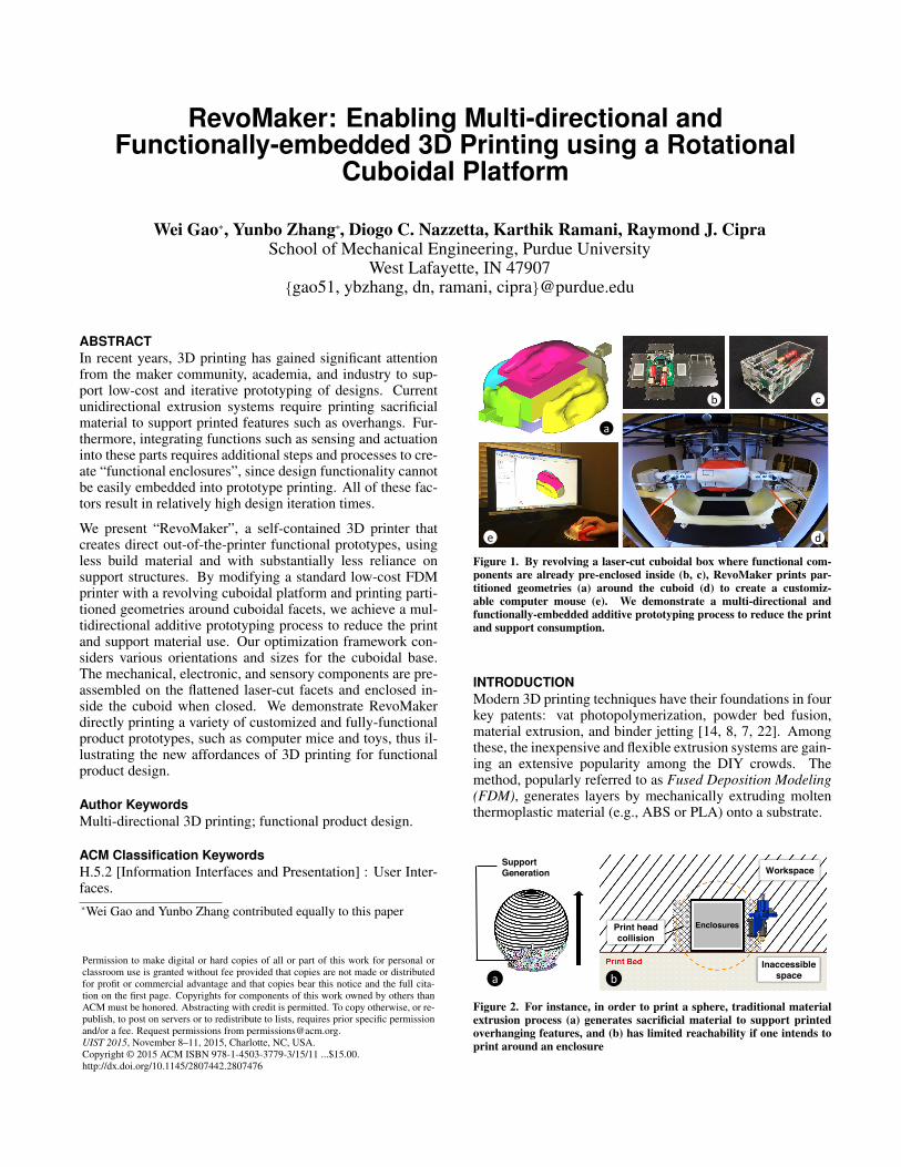
Figure 1. By revolving a laser-cut cuboidal box where functional com-ponents are already pre-enclosed inside (b, c), RevoMaker prints par-titioned geometries (a) around the cuboid (d) to create a customiz-able computer mouse (e). We demonstrate a multi-directional andfunctionally-embedded additive prototyping process to reduce the printand support consumption.
INTRODUCTIONModern 3D printing techniques have their foundations in fourkey patents: vat photopolymerization, powder bed fusion,material extrusion, and binder jetting [14, 8, 7, 22]. Amongthese, the inexpensive and flexible extrusion systems are gain-ing an extensive popularity among the DIY crowds. Themethod, popularly referred to as Fused Deposition Modeling(FDM), generates layers by mechanically extruding moltenthermoplastic material (e.g., ABS or PLA) onto a substrate.
Support Generation
b
Print head collision
Workspace
Inaccessible space
Enclosures
a
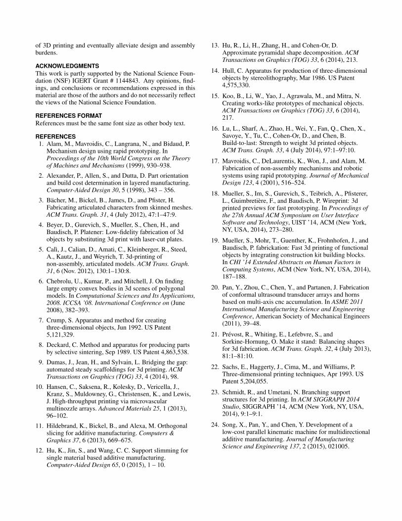
Figure 2. For instance, in order to print a sphere, traditional materialextrusion process (a) generates sacrificial material to support printedoverhanging features, and (b) has limited reachability if one intends toprint around an enclosure

RevoMaker Printflow
Functional Components
b a c d
e f g h Figure 3. (a)-(d) revolving a cuboidal base about the out-of-plane central axis and printing four partitioned geometries around the base. A pair ofhandles are added to the opposite facets, allowing the cuboid to be gripped for the next run of rotation, (e)-(g) revolving the cuboid about the in-planecentral axis and printing the remaining two partitioned geometries, and (h) snapping off two extra handles when the print is completed.
In order to create complex geometries such as overhangs andundercuts, current additive manufacturing systems need toprovide means to support the printed features of subsequentlayers. In the material extrusion process, this is typically doneby printing fine scaffold structures from the build material(See Fig.2(a)). Such sacrificial support structures require ad-ditional material and consume a large portion of the print-ing time. Post-processing operations thereby are necessitatedfor separating the printed objects with built-in support. Themethods and ease of removal of support structure varies byextrusion methods and build materials, including lye bathingfor the soluble support, and mechanical cutting and peelingaway for the non-soluble support.
In addition, current plastics-based 3D printing is more suit-able for fabricating decorative models, design concept proto-types and customized products. Traditional design tools andfabrication methods implicitly prevent designers from encap-sulating full functionalities in the early design concept pro-totyping stage. Therefore, designers are forced to design in-dividual parts using 3D printing, assemble them as done inconventional manufacturing, and iteratively create additionalfunctionalities. We present an alternative 3D printing pro-cess that can combine functional design along with the shapecreation by embedding components during 3D printing. Un-fortunately, using traditional printing and placing such en-closures on the print bed will not allow layer-wise fabrica-tion since the printhead intersects with the enclosure and anygeometry beneath the enclosure is infeasible to print (SeeFig.2(b)).
We demonstrate a multi-directional 3D printing process thatis capable of inherently reducing build and support consump-tion, and producing a new genre of custom products with
higher levels of functionality. The key idea is to enclosefunctional components inside a laser-cut cuboidal enclosure,which is also a printing base inscribed within a desired shape.By revolving the cuboid shown in Fig.3, we print partitionedgeometries on and around each facet. In RevoMaker, thecuboidal base (a) encapsulates advanced functionality theuser does not need to have detailed knowledge of, (b) savestime and print material for 3D printing by using laser cut-ting, (c) doubles up as a platform for 3D printing, and (d)also structurally adheres to the 3D printed material. Our sys-tem affords a high manufacturing precision by (a) seamlesslyprinting exterior skin geometries in a single build (no gap be-tween partitions), (b) enabling directly side-surface function-alities that also interact with housed modules in a compactvolume, and (c) ensuring a strong bond within overlappingpartitions since the print material fuses with itself. Thus weenlarge the design space of 3D printing to go beyond simpleparts using the volume within the 3D printed shape itself toembed functionality. Different use cases that demonstrate thefeasibility are discussed later in this paper.
In general, our design goals for RevoMaker are:
• Lesser use of build material
• Significant reduction of support consumption
• Reduced need of post-processing operation
• Embedding of functional components
Currently our approach is more suitable for the object shapesthat approximate the cuboid, and requires combining lasercutting process and manual user involvement.
RELATED WORK

Hollowing and optimizing support generationPrevious research studies have been dedicated to reduce boththe printing volume and support generation. A natural wayto reduce printing volume is to hollow the model basedon physical-geometric optimization [28]. Another researchintended to improve the structural integrity by generatinghoneycomb-cells inside the model [16]. However, none ofthese existing methods generate an interior space that is well-structured and fully used for functional enclosures. On theother hand, methods were proposed to reduce support ma-terials by optimizing the model orientation for printing [2,25], and optimizing support scaffolding structures that con-sume less material [27, 9, 23, 12]. Due to the unidirectionalprinting process, the reduction of support in general is quitelimited and can hardly be post-processing free.
Fast fabrication of 3D objectsBy introducing intermediate low-fidelity fabrication into tra-ditional slow but hi-fidelity printing process, Mueller et al.and Beyer et al. proposed a variety of alternative fabrica-tion methods, such as printing wireframe mesh of an object[18], substituting sub-volumes of a model with standard Legobuilding blocks [19] and laser-cut parts [4]. These differentapproaches effectively reduced the printing time while pre-serving the shape of a model. Besides, Hansen et al. [10]achieved a parallel printing process via microvascular multi-nozzle Arrays.
Multi-axis 3D printingSong [24] and Pan et al. [20] developed a 6-DoF Stewardmechanism to continuously print conformal features, such astextures or patterns, on curved and irregular surfaces. ThisCNC-based accumulative process enables continuous fabri-cation with different size, shape, and resolution requirements.Traditional multi-axis fabrication solutions might also reducethe need for support by tilting the nozzle or object. However,such systems have higher overhead such as a demanding con-trol strategy for motion synchronization, complexity of me-chanical calibration, and more importantly the difficulty ofadhering print material onto largely slanted or bottom sur-faces due to the effect of gravity. In our approach, by adding1 DOF to a cuboid and using the printer’s own X-, Y- andZ-step precision, we (a) add much greater functionality andcapability to the resulting process and products, and (b) uti-lize gravity to allow the print material to firmly adhere to therotated horizontal surfaces.
Printing with functional effectThere are also many research approaches dedicated to gen-erate functional effects of fabricated products via geometricoptimization on input models. Prevost et al. [21] proposedan approach to generate models which can stand alone by de-forming the initial inputs. Umetani and Schmidt [26] opti-mized the orientation of a model for 3D printing to increasemechanical strength and structural soundness. Other inter-esting works involve printing kinematic mechanisms [1, 17],working prototypes [15], and articulated models [5, 3].
HOW REVOMAKER WORKS
In placing the cuboidal base within a desired shape, a keychallenge is related to how to pose the objective function sothe number of possibilities of cuboidal orientations and print-ing sequences are balanced to reduce the support generationas well as the use of print material. Furthermore, when print-ing one facet after the other, the print nozzle should not in-tersect with the material already printed, and merge the newpartitioned shape well with the old. In this section, we firstdiscuss how we formalize these objectives across many ge-ometric shapes, followed by our mechanical implementationof RevoMaker.
Objective FunctionGiven an input triangular mesh model M = (V,E,F ), weintroduce Cuboidization, an algorithm that generates an in-terior cuboid C, where all six facets Ci
f (i 2 (1, 2, ...6)) ofthe cuboid partition M into six outward regions Mi
ps. Re-cent research effort such as orthogonal slicing [11] and ap-proximate pyramidal decomposition [13] introduce differentpartitioning strategies on the overall shape of an object to im-prove fabrication accuracy and for minimal number of pyra-midal parts. In contrast, the main goals of our Cuboidizationare two fold: (1) create the cuboid with as large volume aspossible to save print materials, and (2) six outward regionsMi
p add up to as few overhangs as possible to save supportmaterial. Considering the time consumption and effort forpost-processing, in our work the reduction of support mate-rial generation was given higher priority over augmenting thecuboid volume. Hence, we define the objective function asfollows:
arg maxC
Fvol(C) s.t.6X
i=1
Foverhang(Mip) = 0, (1)
where Fvol measures the volume of C and Foverhang evalu-ates the overhanging feature of Mi
p. Evaluation of Fvol andFoverhang is not a trivial task since Foverhang depends on C butit can be only evaluated after the region partition is done.Therefore, it is not feasible to analytically solve Eq.1 usingnonlinear optimization approaches.
In our work, an overhang-aware multi-loop optimizationframework shown in Algorithm 1 is proposed to resolve thisproblem. The outer loop uses a Particle Filtering based sam-pling algorithm to generate a set of principal axes for thecuboid (also called cuboidal orientation), see Section “Ini-tial orientation sampling”. Inside the inner loop, by usingthree orthogonal vectors u, v and w as the principal axes forthe cuboid, we generate and compute the size of the largestcuboid inscribed (Section “Cuboid generation”). After ob-taining the cuboids over all orientations, we compare theirvolume and overhanging features, and retain B top-rankedcandidates with the least support consumption for the user toselect the final print. How different printing sequences wouldaffect the resultant partitioning as well as the avoidance ofsupport generation is discussed in Section “Optimization ofprinting sequence”. Currently, our Cuboidization algorithmis more suitable for processing shapes with topological genus

Algorithm 1: Multi-loop CuboidizationInput: M is input model, l is the maximum level of Particle
FilteringOutput: C is the cuboid that partitions M, and S is the
printing sequenceFunction (C, S ) = FindCuboidization(M, l)
currentLevel 0;currentCuboidS et ?;newOrientationS et InitialOrientationS ampling();while currentLevel < l do
foreach orientation Oi 2 newOrientationS et doC GenerateCuboid(M,Oi);(C.V,C.Aoverhang,C.S ) = EvaluateCuboid(M,C);currentCuboidS et += C;
newOrientationS et = OrientationResamping();currentLevel currentLevel + 1;
return BestRanked(currentCuboidS et);Function (V, Aoverhang, S ) = EvaluateCuboid(M,C)
V CalculateVolume(C);Aoverhang +1;foreach S temp 2 All Printing Sequence for C do
Atemp CalculateOverhangingArea(M,C, S temp);if Atemp < Aoverhang then
Aoverhang Atemp;S S temp;
return V, Aoverhang, S ;
of 0, and preferably those that approximate the cuboid. Mod-els with high genus (rings, knots, etc.), long and curved pro-truding features, or massive small curvy features, limit ourapproach towards providing less support structures.
Overhang-aware Cuboidization frameworkInitial orientation sampling
Figure 4. (a) sampling the unit vector wi (b) sampling the unit vectors uiand vi.
In order to find an optimized interior cuboid for each model,we first consider sampling a set of cuboidal orientations us-ing a particle filtering based approach. As each orientationmatrix Oi consists of three unit orthogonal vectors ui, vi andwi as column vectors, the sampling is performed for the threecomponents one after the other. Without loss of generality,wi is determined initially. We uniformly sample K points ona Gauss sphere, and each of the samplings is assigned to wi(see Fig.4 (a)). For each wi, the second uniform samplingis performed on a unit circle laying on the normal plane ofwi in order to obtain L samples of ui and vi (shown in Fig.4
(b)). Note that, as opposite direction results in the same Oi,we consider herein only the semisphere and semicircle, wherethe polar point for semisphere and end point of semicircle arearbitrarily positioned. For each model, there are K ⇥ L orien-tations in total to be evaluated and filtered.
Cuboid generation
Given a determinate orientation, the second part of the al-gorithm generates a cuboid with as large volume as possibleinside M. We use a heuristics-based method [6] to balancethe resultant quality as well as computation efficiency. Thegeneration details are as follows. Followed by the orientationOi, a small enough cuboid Ci is initialized at the center of alargest inscribed sphere within M. The six facets of Ci thenmove along their corresponding normal directions to incre-mentally expand the size of the cuboid. At each augmentationstep, the corner collision is detected. The iteration stops whenno facet can be moved further. All possible cuboids inscribedinside M along orientation Oi are recorded and indexed byvolume, and the one with the maximum volume is returnedas the resultant candidate .
Evaluation of overhangs
With the partitioned model, an overhanging evaluation func-tion is defined as follows:
6X
j=1
X
fk2FM jp
Farea( fk), (2)
Farea( fk) =(
0 i f n fk · nM jp< �
area o f fk otherwise (3)
Farea( fk) measures the overhanging area on each facet fk de-pending on whether the dot product of its normal n fk and thenormal of C j
f is less than the threshold. All results in thispaper use � to be � cos 45�, unless otherwise stated.
Filtering and resampling
Based on the overhang evaluation, we select N orientationswith the least sum of overhanging areas. To avoid selectingtoo many similar cuboids, we discard those orientations withless variation and only the ones with larger than 70% varia-tions are kept. The following equation is used to evaluate thevariation of two orientations Oi and O j:
Fvar = |ui · u j| + |ui · v j| + |ui · w j|+ |vi · u j| + |vi · v j| + |vi · w j|+ |wi · u j| + |wi · v j| + |wi · w j|
(4)
At each selected orientation, we uniformly resample over itsneighborhood region with a radius ✏ on the Gauss sphere, andgenerate the new set of cuboids. The empirical values of Kfor initial sampling and resampling are set as 25 and 10. Weuse L = 10 for both samplings and N = 5 for the resamplingprocess. Thus, for each model we evaluate 1250 orientationsafter two sampling processes in total. The final B top-rankedcandidates with least support material generation are retainedfor user to select by leveraging the physical dimensions offunctional components.

a
1
2
3
4
1
2
3
4 b c
Figure 5. (a) partitioning based on above-facet regions and corner re-gions (b) printing sequence 1 generates support material (c) printing se-quence 2 generates no support material.
Optimization of printing sequenceWhile evaluating the overhanging feature over six partitionedgeometries, it is crucial to determine the optimal printingsequence simultaneously. In order to achieve the minimalnumber of rotations and therefore reduce the effort of han-dling, we define our strategy of printing such that: (1) fouradjacent partitioned geometries about a central axis of thecuboid are printed by intermittently rotating about the axisby 90 degrees, and (2) the rest of the two opposite partitionsare printed afterwards by rotating every 180 degrees about asecond central axis which is orthogonal to the previous one.This reduces the number of degrees of freedom to two andthe intermediate number of handling to one. Through initialpartitioning, the model can be inherently segmented into theprint regions right above each cuboidal facet (the pink, yel-low, green and blue above-regions shown in Fig.5 (a)). As forthe corner regions shown in black in Fig.5 (a), we assign eachof them into its neighboring above-region(s). Here the print-ing strategy is that once the first facet is determined, eachcorner region is always assigned to the later-to-print above-region that follows a single rotational direction (for instancecounterclockwise shown in Fig.5). In doing so, it also gen-erates extended underlying surface to support the corner ge-ometries after each rotation. Note that a different selectionof the initial facet to be printed on results in different sup-port generation scenarios. As shown in Fig.5, the sequence(b) requires support in the right upper corner while in (c) it istotally support-free hence the better choice. For each cuboidwith determinate size and orientation, we search over 30 dif-ferent combinations of printing sequence around six cuboidalfacets and choose the one with less or no support generation.These combinations vary based on which facet is the first to
a b
Figure 6. We extend a standard low-cost FDM printer, UltiMaker 2,with mechanical, electrical and pneumatic devices.
be printed on, the rotational direction and the selection of twofacets that stay as the last-to-print ones.
Mechanical implementation behind RevoMaker
Ultimaker 2 PrinterOur machine design goal is to enhance an existing 3D printerat minimal cost and augmented complexity. Fig.6 (a) showsan assembled view of the mechanical and electrical apparatusthat are extended onto Ultimaker2. All of the models shownin this paper were printed on this modified 3D printer, i.e., anopen-source fused-filament extrusion system with 230mm ⇥225mm ⇥ 205mm build volume and up to 20 microns printaccuracy. The filament material used for printing is the 3mm-diameter Polylactic acid (PLA).
Laser cutting a cuboidal base
Unlike the standard bed material used in FDM printers whereextruded plastic needs to be easily peeled off from the printbed, we select a 3mm-thick Plexiglasr DP-95 acrylic sheet asthe build surface material for each facet of the cuboidal base.This cell-cast material is available with low heat capacity andmatte finish on both sides to ensure a very firm first-layer PLAbonding without any pre-heating process.
a b
Figure 7. (a) a flattened cuboidal net pattern using laser-cut facets andslots; (b) a folded cuboid.
Six rectangular facets and twelve edges comprise a cuboidalbase. We synthesize the interlocking teeth pattern along eachedge so that six facets can be rapidly press-fit together seam-lessly (see Fig.7). In order to level and secure the cuboid dur-ing printing, two 32mm⇥ 15mm rectangular slots are also en-graved on a pair of opposite cuboidal facets (also called side-facets) using laser cutting. Our experimental results show thatfor each model it takes on the average 5 to 10 minutes to lasercut the facets and approximately 1 minute to assemble thecuboid.
Embedding of functional modules
The internal space inside each cuboid base is utilized for em-bedding functionalities. This standardized cuboidal space canhouse a wide variety of mechanical, electronic, sensory andactuation components, including but not restricted to proces-sor chips, sensors, springs, gears and motors. By provid-ing channels in the printed material, external devices suchas lights and wind-up keys can then interconnect with thehoused components inside to enhance visual, motion andmovement functionalities, through the slots and holes alreadyadded on each of six cuboidal facets. Our process is rel-atively simple when compared to the traditional processes

Figure 8. Each gripper from both sides has 3 degrees-of-freedom: (1)translation to fixate and release the cuboidal base, (2) rotation to revolvethe cuboid facets around, and 3) angular motion to apply gripping forceto the handles.
where multiple high-fidelity printed parts must be assembledin 3D while enclosing motors and sensors. We lay downand pre-assemble functional modules on the “flat” unfoldedcuboid. We then close the cuboid by folding, and “coat” theexternal skin shapes over it using our 3D printing process.
Fixation, revolving and gripping
Three degrees-of-freedom are needed for realizing the multi-directional printing: (1) translation along X to fixate and re-lease the cuboidal base, (2) rotation about X to revolve thecuboid facets around, (3) and angular motion to deliver stronggripping to the handles. We attach an acrylic stand with 2 can-tilevered support plates to our build platform. A pair of linearair cylinders sits on the support plates to fixate or release thecuboid from both sides. These magnetically coupled linearcylinders (CY3R-10-65) are powered pneumatically and con-trolled by a solenoid valve (see Fig.6 (b)). To enable the ro-tation, two HerkuleX DRS-0201 robot servos rest on the aircylinders and two connected air fingers (MHY2-10D) pro-vide angular gripping motion. In RevoMaker, we first handdeliver the cuboidal base to the center of the printer. These180-degree air fingers are initially closed and fit into side slotsto secure the cuboid by squeezing. After one partitioned ge-ometry is printed on top of the build surface, the servos syn-chronously rotate the base by 90 degrees. Therefore, fourfacets surrounding the revolute axis can be printed in the firstrun of rotation (see Fig.9 (b)-(e)). Note that during printing,two opposite facets among the four are chosen to add twocollinearly-aligned handles outside the geometries. The pur-pose of adding these handles is for the grippers to secure themodel in the second run of rotation while avoiding directlycontact with the printed surface .
After we releasing the grippers, we rotate the part such thatthe grippers close over the handles from both sides. Once theremaining two partitioned geometries are printed, we snapoff two handles for completing the print. Throughout thewhole fabrication process, we calibrate the surface location ofthe cuboid twice before printing the first and the fifth facets.The corner coordinates of the rectangular facets and slots arerecorded as the reference coordinates for the print head tostart printing.
ALGORITHMIC AND PROTOTYPICAL RESULTS
Sculptural objectsAccording to the Cuboidization results on a number of genus0 models with different overhanging features on different lo-cations, including man-made art objects and organic forms,our optimization framework generates cuboids that allow zerosupport material to the printed geometries. Five sculpturalmodels including a small Hexacronic Icositetrahedron, spher-ical ball, Max Planck, French bulldog, and Mickey Mousewere fabricated to verify our optimization framework with re-duction of print and support material. Fig.9 (a) shows the par-titioned result of a small Hexacronic Icositetrahedron where6 “mountain”s are extruded and connected from 6 cuboidalfacets, respectively. After laser cutting the cuboid and print-
a b
g
e
c
h
f
d
Figure 9. (a) Cuboidal generation and partitioned results of a small Hex-acronic Icositetrahedron with the “UIST 2015” logo. (b)-(g) printing 6partitioned geometries intermittently around a revolving cuboidal baseusing our method. (h) final print.

Table 1. Comparison of time and total material reduction using RevoMaker and Ultimaker 2.
ModelsRevoMaker Ultimaker 2 time total material
total time build volume (cm3)time (hh:mm) build volume (cm3) reduction reduction
(hh:mm) tmin tmax Vmin (Vsupport) Vmax (Vsupport) compared to tmin compared to Vmin
Sphere 4:03 61.7 4:58 4:58 77.9 (0.3) 77.9 (0.3) 18.4% 20.8%Max Planck 6:11 114.6 8:13 9:16 142.6 (7.4) 163.8 (28.6) 23.5% 19.6%
Bulldog 7:36 133.8 10:52 12:43 177.3 (26.7) 215.9 (65.3) 20.8% 24.5%Mickey 6:15 112.2 8:22 15:01 138.4 (6.4) 257.2 (125.2) 25.3% 18.9%
Star 9:06 165.5 11:25 13:32 200.6 (12.6) 231.9 (43.9) 20.3% 17.5%PC Mouse 2:55 48.4 4:38 6:44 76.7 (10.9) 111.3 (45.6) 37.0% 36.8%Bulbasaur 5:24 93.7 6:37 7:17 109.7 (1.7) 121.6 (13.6) 18.39% 14.6%
*By placing a model in different orientations, tmin and tmax are the minimum and maximum time duration using Ultimaker 2; Vmin and Vmax are the minimumand maximum consumption of overall material (build + support), Vsupport is only the consumption of support material. Using RevoMaker, the time statistics of
Cuboidization for each selected model (top down), included in the total time, are 30s, 2min 33s, 6min 45s, 5min 03s, 1min 10s, 1min 02 s, 4 min 17s,respectively.
ing around each facet (see Fig.9 (b)-(g)), we achieve the finalprint with 6 different colors and a “UIST 2015” logo on it.Fig.10 shows the rest of the models with their support gen-eration using Ultimaker 2, partitioned results and final printsusing RevoMaker. In order to validate the strength in our ap-proach to save time, build material and support material, wecompare the fast-printing results using both RevoMaker andUltimaker 2 over seven selected models.
French bulldog Mickey Mouse Max Planck Sphere ball
Figure 10. first row: visualization of support generation for a sphereball, Max Planck, French bulldog and Mickey Mouse head using existingFDM printing process in Ultimaker2 (the model is oriented where lesssupport structures are created. second row: partitioned results of eachmodel. third row: prototypical results of each model
As shown in Table. 1, comparing to tmin and Vmin, Revo-maker achieves a 23.4% reduction of printing time, and21.8% reduction of total material consumption on averageusing the lightest infill setup. The main strength of ourmulti-directional printing process is that it provides signifi-cant reduction of support material generation. We observethat the regular unidirectional extrusion process initially gen-erates skirts and rafts on the print bed to smooth the printingflow and to assist bed adhesion, then it prints 3⇠4 solid ad-hering layers and followed by the hollowed structures inside.Our approach requires periodically printing 1 adhering layer6 times for the six partitioned geometries. Together with the
two added handles, it leads to a modest improvement in print-ing time and overall material consumption.
Custo “mice”: Customizable miceWe customize a computer mouse for an ergonomical fit tothe palm and tailored functionalities. Dating back to 1964,Dr. Douglas Engelbart invented the first computer pointingdevice with one button on top and two wheels on the under-side. The mouse began to multiply rapidly with embeddedmechanical, optical and electronic systems. However, creat-ing a mouse design from scratch and prototyping enclosurescan be an iterative and daunting task especially for novices.It requires 3D modeling, molding/tooling design and physicalassembly to be integrated seamlessly to fit all individual com-ponents inside an exterior shell. In addition, with traditionalinjection molding, it is difficult to mold reentrant features andside-surface functions such as buttons.
a a b
d c e
Figure 11. shows (a) user interaction to tailor the shape of his/herergonomical-fitting mouse using Play Doh, (b) 3D scanning, (c) hollow-ing the digital model with slot-cuts to separate out three button areas,(d) six partitioning geometries around an embedded cuboid, and (e) en-close buttons, printed circuit board and optical components inside thelaser-cut cuboid.
To demonstrate the whole fabrication process, Play Doh wasinitially used to create the shape of the mouse (see Fig.11 (a)).In doing so, the user is able to quickly verify a list of cus-tomizable human factors regarding the size range of hands,finger extension and palm comfort. In our custo“mice” theuser also specifies the middle-click to be operated by thumb

Figure 12. Revomaker prints the partitioned geometries around thecuboidal enclosure and delivers a functional and ergonomical computermouse right after printing.
on the side of the mouse. Then its shape was captured using a3D scanner, shown in Fig.11 (b). The algorithm generates thesize of the cuboidal base and provides slot-cuts for the but-ton areas in the partitioned geometries, shown in Fig.11 (c,d).Matching slot-cuts on the cuboid provide a cantilever whichdeflects to actuate internal switch when the external buttonarea is pressed. Fig.11 (e) shows that all added functionalmodules are pre-assembled on the flattened laser-cut facetsand enclosed inside the cuboid when closed. These modulesinclude 3 buttons for left-, middle-, and right-clicking; light-emitting diodes (LEDs) and photodiodes to detect movementrelative to the underlying surface; printed circuit board (PCB)with electrical resistors, capacitors, integrated circuits (ICs)mounted on; and rechargeable battery. Lastly, the custom-made geometries are printed around the cuboid to complete
d d
a b
c
Figure 13. shows (a) support generation for Bulbasaur, (b) six parti-tioning geometries around an embedded cuboid, (c) pre-assembling thewind-up motor and batteries onto flattened laser-cut facets and closingthe cuboid as a printing base, (d) printing the Bulbasaur shape aroundthe cuboid, and (e) winding the Bulbasaur up to trigger tail-wagglingand eye-blinking.
the prototyping and ready for use directly after printing (seeFig.12).
Wind-up PokemonTo further expand the design space for functional products,we enclose passive-actuated wind-up motor with gears andsprings inside the cuboidal base. One of the popular Pokemoncharacters, Bulbasaur, was selected in this example due to itslarge amount of overhanging features, shown in Fig.13 (a).Similar to the previous procedures, we partition six geome-tries around an embedded cuboid (see Fig.13 (b)), and en-close the cuboid with laser-cut facets and kinematic compo-nents including the wind-up motor and batteries (see Fig.13(c)). After taking it out from Revomaker, we insert anotherPokemon character Pikachu’s tail into the back hole of Bul-basaur, and a wind-up key into the side hole of Bulbasaur towaggle the tail. Besides, one can insert a pair of LEDs intothe eyes of Bulbasaur, and the eyes start blinking simultane-ously after winding, shown in Fig.13 (e).
CONCLUSION AND FUTURE WORKIn this paper, we have explored a multi-directional 3D print-ing process to not only reduce the consumption of print andsupport material, but also to enable a new breed of cus-tom products with embedded functionalities. We proposethe Cuboidization algorithm to generate a cuboidal enclosure,that is also the printing base. It has as large a volume in-side the model and with as few overhangs as possible. UsingRevomaker, we printed a number of sculptural models andtwo functional products, i.e., a customizable computer mouseand wind-up toy. We thus demonstrated its capabilities incombining functional design along with the shape creation.
a b
Figure 14. shows inapplicable cases where overhanging features can notbe largely reduced. For instance, (a) a 3D shape with high topologicalgenus such as a ring of genus one, or (b) with long and branched pro-truding features such as a tree.
As future work, we will explore the extension of our cur-rent Cuboidization algorithm to generate a prismatic polyhe-dral structure as the printing base, in order to further reducethe support consumption. In doing so, the overhanging fea-tures on a model can be further partitioned and eliminatedwhile printing over more polyhedral facets. In addition, forcomplex geometries that cannot be approximated by a singlecuboid, we will explore using sub-cuboids for better approxi-mation, and to further minimize the print and support genera-tion. This also allows additional functions to be encapsulatedinside multiple enclosures. For those 3D shapes with highgenus, long protruding and massive curvy features, our ap-proach still requires support generation after partitioning, seein Fig.14. We believe that the modularization of functional-ities and integration of 3D shapes will open up a new genre
of 3D printing and eventually alleviate design and assemblyburdens.
ACKNOWLEDGMENTSThis work is partly supported by the National Science Foun-dation (NSF) IGERT Grant # 1144843. Any opinions, find-ings, and conclusions or recommendations expressed in thismaterial are those of the authors and do not necessarily reflectthe views of the National Science Foundation.
REFERENCES FORMATReferences must be the same font size as other body text.
REFERENCES1. Alam, M., Mavroidis, C., Langrana, N., and Bidaud, P.
Mechanism design using rapid prototyping. InProceedings of the 10th World Congress on the Theoryof Machines and Mechanisms (1999), 930–938.
2. Alexander, P., Allen, S., and Dutta, D. Part orientationand build cost determination in layered manufacturing.Computer-Aided Design 30, 5 (1998), 343 – 356.
3. Bacher, M., Bickel, B., James, D., and Pfister, H.Fabricating articulated characters from skinned meshes.ACM Trans. Graph. 31, 4 (July 2012), 47:1–47:9.
4. Beyer, D., Gurevich, S., Mueller, S., Chen, H., andBaudisch, P. Platener: Low-fidelity fabrication of 3dobjects by substituting 3d print with laser-cut plates.
5. Calı, J., Calian, D., Amati, C., Kleinberger, R., Steed,A., Kautz, J., and Weyrich, T. 3d-printing ofnon-assembly, articulated models. ACM Trans. Graph.31, 6 (Nov. 2012), 130:1–130:8.
6. Chebrolu, U., Kumar, P., and Mitchell, J. On findinglarge empty convex bodies in 3d scenes of polygonalmodels. In Computational Sciences and Its Applications,2008. ICCSA ’08. International Conference on (June2008), 382–393.
7. Crump, S. Apparatus and method for creatingthree-dimensional objects, Jun 1992. US Patent5,121,329.
8. Deckard, C. Method and apparatus for producing partsby selective sintering, Sep 1989. US Patent 4,863,538.
9. Dumas, J., Jean, H., and Sylvain, L. Bridging the gap:automated steady scaffoldings for 3d printing. ACMTransactions on Graphics (TOG) 33, 4 (2014), 98.
10. Hansen, C., Saksena, R., Kolesky, D., Vericella, J.,Kranz, S., Muldowney, G., Christensen, K., and Lewis,J. High-throughput printing via microvascularmultinozzle arrays. Advanced Materials 25, 1 (2013),96–102.
11. Hildebrand, K., Bickel, B., and Alexa, M. Orthogonalslicing for additive manufacturing. Computers &Graphics 37, 6 (2013), 669–675.
12. Hu, K., Jin, S., and Wang, C. C. Support slimming forsingle material based additive manufacturing.Computer-Aided Design 65, 0 (2015), 1 – 10.
13. Hu, R., Li, H., Zhang, H., and Cohen-Or, D.Approximate pyramidal shape decomposition. ACMTransactions on Graphics (TOG) 33, 6 (2014), 213.
14. Hull, C. Apparatus for production of three-dimensionalobjects by stereolithography, Mar 1986. US Patent4,575,330.
15. Koo, B., Li, W., Yao, J., Agrawala, M., and Mitra, N.Creating works-like prototypes of mechanical objects.ACM Transactions on Graphics (TOG) 33, 6 (2014),217.
16. Lu, L., Sharf, A., Zhao, H., Wei, Y., Fan, Q., Chen, X.,Savoye, Y., Tu, C., Cohen-Or, D., and Chen, B.Build-to-last: Strength to weight 3d printed objects.ACM Trans. Graph. 33, 4 (July 2014), 97:1–97:10.
17. Mavroidis, C., DeLaurentis, K., Won, J., and Alam, M.Fabrication of non-assembly mechanisms and roboticsystems using rapid prototyping. Journal of MechanicalDesign 123, 4 (2001), 516–524.
18. Mueller, S., Im, S., Gurevich, S., Teibrich, A., Pfisterer,L., Guimbretiere, F., and Baudisch, P. Wireprint: 3dprinted previews for fast prototyping. In Proceedings ofthe 27th Annual ACM Symposium on User InterfaceSoftware and Technology, UIST ’14, ACM (New York,NY, USA, 2014), 273–280.
19. Mueller, S., Mohr, T., Guenther, K., Frohnhofen, J., andBaudisch, P. fabrickation: Fast 3d printing of functionalobjects by integrating construction kit building blocks.In CHI ’14 Extended Abstracts on Human Factors inComputing Systems, ACM (New York, NY, USA, 2014),187–188.
20. Pan, Y., Zhou, C., Chen, Y., and Partanen, J. Fabricationof conformal ultrasound transducer arrays and hornsbased on multi-axis cnc accumulation. In ASME 2011International Manufacturing Science and EngineeringConference, American Society of Mechanical Engineers(2011), 39–48.
21. Prevost, R., Whiting, E., Lefebvre, S., andSorkine-Hornung, O. Make it stand: Balancing shapesfor 3d fabrication. ACM Trans. Graph. 32, 4 (July 2013),81:1–81:10.
22. Sachs, E., Haggerty, J., Cima, M., and Williams, P.Three-dimensional printing techniques, Apr 1993. USPatent 5,204,055.
23. Schmidt, R., and Umetani, N. Branching supportstructures for 3d printing. In ACM SIGGRAPH 2014Studio, SIGGRAPH ’14, ACM (New York, NY, USA,2014), 9:1–9:1.
24. Song, X., Pan, Y., and Chen, Y. Development of alow-cost parallel kinematic machine for multidirectionaladditive manufacturing. Journal of ManufacturingScience and Engineering 137, 2 (2015), 021005.

25. Thrimurthulu, K., Pandey, P., and Reddy, N. Optimumpart deposition orientation in fused deposition modeling.International Journal of Machine Tools andManufacture 44, 6 (2004), 585 – 594.
26. Umetani, N., and Schmidt, R. Cross-sectional structuralanalysis for 3d printing optimization. SIGGRAPH Asia(2013), 5.
27. Vanek, J., Galicia, J., and Benes, B. Clever support:Efficient support structure generation for digitalfabrication. Computer Graphics Forum 33, 5 (2014),117–125.
28. Wang, W., Wang, T., Yang, Z., Liu, L., Tong, X., Tong,W., Deng, J., Chen, F., and Liu, X. Cost-effectiveprinting of 3d objects with skin-frame structures. ACMTrans. Graph. 32, 6 (Nov. 2013), 177:1–177:10.