Embed Size (px)
Citation preview

I:\SLF\55\8.doc
E
SUB-COMMITTEE ON STABILITY AND LOAD LINES AND ON FISHING VESSELS SAFETY 55th session Agenda item 8
SLF 55/8
12 July 2012 Original: ENGLISH
REVISION OF SOLAS CHAPTER II-1 SUBDIVISION
AND DAMAGE STABILITY REGULATIONS
Report of the working group at SLF 54 (part 2)
Submitted by the Chairman of the Working Group
SUMMARY
Executive summary: This document provides part 2 of the report of the Working Group on Subdivision and Damage Stability established at SLF 54
Strategic direction: 5.2
High-level action: 5.2.1
Planned output: 5.2.1.17
Action to be taken: Paragraph 6
Related documents: SLF 54/WP.5 and SLF 54/17
General 1 The Working Group on Subdivision and Damage Stability (SDS) met from 16 to 18 January 2012 (part 1) and 19 January 2012 (part 2) under the chairmanship of Mr. H. Bruhns (Germany). 2 The group was attended by delegates from the following Member Governments:
BAHAMAS BRAZIL CANADA CHINA DENMARK FINLAND FRANCE GERMANY JAPAN MALAYSIA MARSHALL ISLANDS
NETHERLANDS NORWAY POLAND REPUBLIC OF KOREA RUSSIAN FEDERATION SPAIN SWEDEN TURKEY UNITED KINGDOM UNITED STATES VANUATU

SLF 55/8 Page 2
I:\SLF\55\8.doc
and the following Associate Member of IMO:
HONG KONG, CHINA 3 The group was also attended by an observer from the following intergovernmental organization: EUROPEAN COMMISSION (EC) and observers from the following non-governmental organizations in consultative status:
INTERNATIONAL CHAMBER OF SHIPPING (ICS) INTERNATIONAL ASSOCIATION OF CLASSIFICATION SOCIETIES (IACS) CRUISE LINES INTERNATIONAL ASSOCIATION (CLIA) THE ROYAL INSTITUTION OF NAVAL ARCHITECTS (RINA)
Terms of reference 4 For the terms of reference, reference is made to document SLF 54/17, paragraphs 4.7, 6.6, 7.6, 8.6 and 13.4. 5 The group prepared draft amendments and comments to SOLAS chapter II-1 and to the Explanatory Notes to SOLAS chapter II-1 subdivision and damage stability regulations (resolution MSC.281(85)), as set out in the annex, which will be further considered by the SDS Correspondence Group. Action requested of the Sub-Committee 6 The Sub-Committee is invited to approve the report in general and, in particular, note the contents of the annex.
***

SLF 55/8 Annex, page 1
I:\SLF\55\8.doc
ANNEX
SOLAS CHAPTER II-1 (CONSOLIDATED EDITION 2009) WITH THE EXPLANATORY NOTES TO SOLAS CHAPTER II-1 SUBDIVISION AND DAMAGE STABILITY
REGULATIONS (RESOLUTION MSC.281(85))
Applicable to passenger and cargo ships with keels laid on or after 1 January 2009 Key to colour codes used in this document* SOLAS Consolidated Edition 2009 Current SOLAS text Resolution MSC.281(85) Explanatory Notes to SOLAS chapter II-1
subdivision and damage stability regulations (EN)
Agreed regulatory text changes Agreed changes to SOLAS (SLF 53/WP.6) Agreed EN text changes Agreed changes to EN text (SLF 53/WP.6) Proposed regulatory text changes Changes to SOLAS proposed by the
SDS Correspondence Group Proposed EN text changes Changes to EN text proposed by the
SDS Correspondence Group Qxx Question number in working document [Coordinator's Comments:] Guidance Notes, etc. Medium to long-term Items needing further work after SLF 54
* It should be noted that, although this document is not printed in colour, it can be downloaded from
IMODOCS for the colour codes.

SLF 55/8 Annex, page 2
I:\SLF\55\8.doc
SOLAS regulations as amended on 1 January 2009 This document contains the amendments to the old SOLAS chapter II-1, parts A, B and B-1, which have been completely replaced by the following regulations, now incorporated into the SOLAS Consolidated Edition 2009. Regulations shown in red have Explanatory Notes. Part A – General Regulation 1 Application Regulation 2 Definitions Regulation 3 Definitions relating to parts C, D and E Part B – Subdivision and stability Regulation 4 General Part B-1 – Stability Regulation 5 Intact stability information Regulation 5-1 Stability information to be supplied to the master Regulation 6 Required subdivision index R Regulation 7 Attained subdivision index A Regulation 7-1 Calculation of the factor pi
Regulation 7-2 Calculation of the factor si Regulation 7-3 Permeability Regulation 8 Special requirements concerning passenger ship stability Regulation 8-1 System capabilities and operational information after a flooding casualty on
passenger ships Part B-2 – Subdivision, watertight and weathertight Integrity Regulation 9 Double bottoms in passenger ships and cargo ships other than tankers Regulation 10 Construction of watertight bulkheads Regulation 11 Initial testing of watertight bulkheads, etc. Regulation 12 Peak and machinery space bulkheads, shaft tunnels, etc. Regulation 13 Openings in watertight bulkheads below the bulkhead deck in passenger ships Regulation 13-1 Openings in watertight bulkheads and internal decks in cargo ships Regulation 14 Passenger ships carrying goods vehicles and accompanying personnel Regulation 15 Openings in the shell plating below the bulkhead deck of passengers ships
and the freeboard deck of cargo ships Regulation 15-1 External openings in cargo ships Regulation 16 Construction and initial tests of watertight doors, sidescuttles, etc. Regulation 16-1 Construction and initial tests of watertight decks, trunks, etc. Regulation 17: Internal watertight integrity of passenger ships above the bulkhead deck Regulation 17-1 Integrity of the hull and superstructure, damage prevention and control on
ro-ro passenger ships Part B-3 – Subdivision load line assignment for passenger ships Regulation 18 Assigning, marking and recording of subdivision load lines for passenger ships

SLF 55/8 Annex, page 3
I:\SLF\55\8.doc
Part B-4 – Stability management Regulation 19 Damage control information Regulation 20 Loading of [passenger] [Q53D] ships Regulation 21 Periodical operation and inspection of watertight doors, etc., in passenger
ships Regulation 22 Prevention and control of water ingress, etc. Regulation 22-1 Flooding detection systems for passenger ships carrying 36 or more persons
constructed on or after 1/7/2010 Regulation 23 Special requirements for ro-ro passenger ships Regulation 24 [Additional requirements for p][P]revention and control of water ingress, etc.,
in cargo ships [Q58D] Regulation 25 Water level detectors on single hold cargo ships other than bulk carriers Part C – Machinery installations Regulation 35-1 Bilge Pumping Arrangements For Information Only Associated MSC resolutions Adoption of Amendments to the International Convention for the Safety of Life at Sea, 1974, as amended (resolution MSC.216(82), adopted on 8 October 2006) Recommendation on a standard method for evaluating cross-flooding arrangements (resolution MSC.245(83), adopted on 12 October 2007) Adoption of Amendments to the International Convention for the Safety of Life at Sea, 1974, as amended (resolution MSC.269(85), adopted on 4 December 2008) [Amendments not included in SOLAS Consolidated Edition 2009 but highlighted thus in this document] Explanatory Notes to the SOLAS chapter II-1 subdivision and damage stability regulations (resolution MSC.281(85), adopted on 4 December 2008) Associated MSC circulars Guidance Notes on the integrity of flooding boundaries above the bulkhead deck of passenger ships (MSC/Circ.541, dated 19 July 1990) Unified Interpretation regarding timber deck cargo in the context of damage stability requirements (MSC/Circ.998, dated 25 July 2001) Unified Interpretations to SOLAS chapter II-1, part B-1, regulation 5 regarding stability information for passenger and cargo ships (lightweight check) (MSC/Circ.1158, dated 24 May 2005) Unified Interpretations to SOLAS chapter II-1, regulation 12 regarding bow doors and the extension of the collision bulkhead (MSC.1/Circ.1211, dated 25 May 2006) Performance Standards for the systems and services to remain operational on passenger ships for safe return to port and orderly evacuation and abandonment after a casualty (MSC.1/Circ.1214, dated 15 December 2006)

SLF 55/8 Annex, page 4
I:\SLF\55\8.doc
Guidelines for damage control plans and information to the master (MSC.1/Circ.1245, dated 29 October 2007) Interpretation of alterations and modifications of a major character (MSC.1/Circ.1246, dated 29 October 2007, which supersedes MSC/Circ.650) Guidelines for flooding detection systems on passenger ships (MSC.1/Circ.1291, dated 9 December 2008) Guidelines for the drainage of fire-fighting water from closed vehicle and ro-ro spaces and special category spaces of passenger and cargo ships (MSC.1/Circ.1320, dated 11 June 2009) Guidance for watertight doors on passenger ships which may be opened during navigation (MSC.1/Circ.1380, dated 10 December 2010)
SLF 55/8 Annex, page 5
I:\SLF\55\8.doc
EXPLANATORY NOTES TO THE SOLAS CHAPTER II-1 SUBDIVISION AND DAMAGE STABILITY REGULATIONS
Contents
Part A – INTRODUCTION
Part B – GUIDANCE ON INDIVIDUAL SOLAS CHAPTER II-1 SUBDIVISION AND
DAMAGE STABILITY REGULATIONS Regulation 1 Application Regulation 2 Definitions Regulation 4 General Regulation 5 Intact stability information Regulation 5-1 Stability information to be supplied to the master Regulation 6 Required subdivision index R Regulation 7 Attained subdivision index A Regulation 7-1 Calculation of the factor pi
Regulation 7-2 Calculation of the factor si
Regulation 7-3 Permeability Regulation 8 Special requirements concerning passenger ship stability Regulation 8-1 System capabilities and operational information after a flooding casualty
on passenger ships Regulation 9 Double bottoms in passenger ships and cargo ships other than tankers Regulation 10 Construction of watertight bulkheads Regulation 12 Peak and machinery space bulkheads, shaft tunnels, etc. Regulation 13 Openings in watertight bulkheads below the bulkhead deck in passenger
ships Regulation 13-1 Openings in watertight bulkheads and internal decks in cargo ships Regulation 15 Openings in the shell plating below the bulkhead deck of passenger ships
and the free board deck of cargo ships Regulation 15-1 External openings in cargo ships Regulation 16 Construction and initial tests of watertight doors, sidescuttles, etc. Regulation 17 Internal watertight integrity of passenger ships above the bulkhead deck Appendix Guidelines for the preparation of subdivision and damage stability
calculations

SLF 55/8 Annex, page 6
I:\SLF\55\8.doc
PART A
INTRODUCTION
1 The harmonized SOLAS regulations on subdivision and damage stability, as contained in revised SOLAS chapter II-1 are based on a probabilistic concept which uses the probability of survival after collision as a measure of ships' safety in a damaged condition. This probability is referred to as the "attained subdivision index A" in the regulations. This can be considered an objective measure of ship safety and, ideally, there would be no need to supplement this index by any deterministic requirements. 2 The philosophy behind the probabilistic concept is that two different ships with the same attained index are of equal safety and, therefore, there is no need for special treatment of specific parts of the ship, even if they are able to survive different damages. The only areas which are given special attention in these regulations are the forward and bottom regions which are dealt with by special subdivision rules provided for the cases of ramming and grounding. 3 Only a few deterministic elements, which were necessary to make the concept practicable, have been included. It was also necessary to include a deterministic "minor damage" on top of the probabilistic regulations for passenger ships to avoid ships being designed with what might be perceived as unacceptably vulnerable spots in some part of their length. 4 It is easily recognized that there are many factors that will affect the final consequences of hull damage to the ship. These factors are random and their influence is different for ships with different characteristics. For example, it would seem obvious that in ships of similar size carrying different amounts of cargo, damages of similar extents may lead to different results because of differences in the range of permeability and draught during service. The mass and velocity of the ramming ship is obviously another random variable. 5 Due to this, the effect of a three-dimensional damage to a ship with given watertight subdivision depends on the following circumstances:
.1 which particular space or group of adjacent spaces is flooded; .2 the draught, trim and intact metacentric height at the time of damage; .3 the permeability of affected spaces at the time of damage; .4 the sea state at the time of damage; and .5 other factors, such as possible heeling moments due to unsymmetrical
weights. 6 Some of these circumstances are interdependent and the relationship between them and their effects may vary in different cases. Additionally, the effect of hull strength on penetration will obviously have some effect on the results for a given ship. Since the location and size of the damage is random, it is not possible to state which part of the ship becomes flooded. However, the probability of flooding a given space can be determined if the probability of occurrence of certain damages is known from experience, that is, damage statistics. The probability of flooding a space is then equal to the probability of occurrence of all such damages which just open the considered space to the sea.

SLF 55/8 Annex, page 7
I:\SLF\55\8.doc
7 For these reasons and because of mathematical complexity as well as insufficient data, it would not be practicable to make an exact or direct assessment of their effect on the probability that a particular ship will survive a random damage if it occurs. However, accepting some approximations or qualitative judgments, a logical treatment may be achieved by using the probability approach as the basis of a comparative method for the assessment and regulation of ship safety. 8 It may be demonstrated by means of probability theory that the probability of ship survival should be calculated as a sum of probabilities of its survival after flooding each single compartment, each group of two, three, etc., adjacent compartments multiplied, respectively, by the probabilities of occurrence of such damages as lead to the flooding of the corresponding compartment or group of compartments. 9 If the probability of occurrence for each of the damage scenarios the ship could be subjected to is calculated and then combined with the probability of surviving each of these damages with the ship loaded in the most probable loading conditions, we can determine the attained index A as a measure for the ship's ability to sustain a collision damage. 10 It follows that the probability that a ship will remain afloat without sinking or capsizing as a result of an arbitrary collision in a given longitudinal position can be broken down to:
.1 the probability that the longitudinal centre of damage occurs in just the
region of the ship under consideration; .2 the probability that this damage has a longitudinal extent that only includes
spaces between the transverse watertight bulkheads found in this region; .3 the probability that the damage has a vertical extent that will flood only the
spaces below a given horizontal boundary, such as a watertight deck; .4 the probability that the damage has a transverse penetration not greater
than the distance to a given longitudinal boundary; and .5 the probability that the watertight integrity and the stability throughout the
flooding sequence is sufficient to avoid capsizing or sinking. 11 The first three of these factors are solely dependent on the watertight arrangement of the ship, while the last two depend on the ship's shape. The last factor also depends on the actual loading condition. By grouping these probabilities, calculation of the probability of survival, or attained index A, have been formulated to include the following probabilities:
.1 the probability of flooding each single compartment and each possible
group of two or more adjacent compartments; and .2 the probability that the stability after flooding a compartment or a group of
two or more adjacent compartments will be sufficient to prevent capsizing or dangerous heeling due to loss of stability or to heeling moments in intermediate or final stages of flooding.
12 This concept allows a rule requirement to be applied by requiring a minimum value of A for a particular ship. This minimum value is referred to as the "required subdivision index R" in the present regulations and can be made dependent on ship size, number of passengers or other factors legislators might consider important.

SLF 55/8 Annex, page 8
I:\SLF\55\8.doc
13 Evidence of compliance with the rules then simply becomes:
A ≥ R As explained above, the attained subdivision index A is determined by a formula for the entire probability as the sum of the products for each compartment or group of compartments of the probability that a space is flooded, multiplied by the probability that the ship will not capsize or sink due to flooding of the considered space. In other words, the general formula for the attained index can be given in the form:
A = Σ pi.si
Subscript "i" represents the damage zone (group of compartments) under consideration within the watertight subdivision of the ship. The subdivision is viewed in the longitudinal direction, starting with the aftmost zone/compartment. The value of "pi" represents the probability that only the zone "i" under consideration will be flooded, disregarding any horizontal subdivision, but taking transverse subdivision into account. Longitudinal subdivision within the zone will result in additional flooding scenarios, each with their own probability of occurrence.
The value of "si" represents the probability of survival after flooding the zone "i" under consideration. 14 Although the ideas outlined above are very simple, their practical application in an exact manner would give rise to several difficulties if a mathematically perfect method was to be developed. As pointed out above, an extensive but still incomplete description of the damage will include its longitudinal and vertical location as well as its longitudinal, vertical and transverse extent. Apart from the difficulties in handling such a five-dimensional random variable, it is impossible to determine its probability distribution very accurately with the presently available damage statistics. Similar limitations are true for the variables and physical relationships involved in the calculation of the probability that a ship will not capsize or sink during intermediate stages or in the final stage of flooding. 15 A close approximation of the available statistics would result in extremely numerous and complicated computations. In order to make the concept practicable, extensive simplifications are necessary. Although it is not possible to calculate the exact probability of survival on such a simplified basis, it has still been possible to develop a useful comparative measure of the merits of the longitudinal, transverse and horizontal subdivision of the ship.

SLF 55/8 Annex, page 9
I:\SLF\55\8.doc
CHAPTER II-1
CONSTRUCTION – STRUCTURE, SUBDIVISION AND STABILITY, MACHINERY AND ELECTRICAL INSTALLATIONS (Extracts from SOLAS Consolidated Edition 2009)
Part A
General
Regulation 1
Application 1.1 Unless expressly provided otherwise, this chapter shall apply to ships the keels of which are laid or which are at a similar stage of construction on or after 1 January 2009. 1.2 For the purpose of this chapter, the term a similar stage of construction means the stage at which:
.1 construction identifiable with a specific ship begins; and
.2 assembly of that ship has commenced comprising at least 50 tonnes or one per cent of the estimated mass of all structural material, whichever is less.
1.3 For the purpose of this chapter:
.1 the expression ships constructed means ships the keels of which are laid or
which are at a similar stage of construction; .2 the expression all ships means ships constructed before, on or
after 1 January 2009; .3 a cargo ship, whenever built, which is converted to a passenger ship shall
be treated as a passenger ship constructed on the date on which such a conversion commences;
.4 the expression alterations and modifications of a major character means, in
the context of cargo ship subdivision and stability, any modification to the construction which affects the level of subdivision of that ship. Where a cargo ship is subject to such modification, it shall be demonstrated that the A/R ratio calculated for the ship after such modifications is not less than the A/R ratio calculated for the ship before the modification. However, in those cases where the ship's A/R ratio before modification is equal to or greater than unity, it is only necessary that the ship after modification has an A value which is not less than R, calculated for the modified ship. [Q1]
2 Unless expressly provided otherwise, for ships constructed before 1 January 2009, the Administration shall ensure that the requirements which are applicable under chapter II-1 of the International Convention for the Safety of Life at Sea, 1974, as amended by resolutions MSC.1(XLV), MSC.6(48), MSC.11(55), MSC.12(56), MSC.13(57), MSC.19(58), MSC.26(60), MSC.27(61), Resolution 1 of the 1995 SOLAS Conference, MSC.47(66), MSC.57(67), MSC.65(68), MSC.69(69), MSC.99(73), MSC.134(76), MSC.151(78) and MSC.170(79) are complied with.

SLF 55/8 Annex, page 10
I:\SLF\55\8.doc
3 All ships which undergo repairs, alterations, modifications and outfitting related thereto shall continue to comply with at least the requirements previously applicable to these ships. Such ships, if constructed before the date on which any relevant amendments enter into force, shall, as a rule, comply with the requirements for ships constructed on or after that date to at least the same extent as they did before undergoing such repairs, alterations, modifications or outfitting. Repairs, alterations and modifications of a major character and outfitting related thereto shall meet the requirements for ships constructed on or after the date on which any relevant amendments enter into force, in so far as the Administration deems reasonable and practicable. Regulation 1.3 1 If a passenger ship built before 1 January 2009 undergoes alterations or modifications of major character, it may still remain under the damage stability regulations applicable to ships built before 1 January 2009, except in the case of a cargo ship being converted to a passenger ship. 2 Application of MSC.1/Circ.1246 is limited to cargo ships constructed before 1 January 2009 3 A cargo ship constructed on or after 1 January 2009 of less than 80 m in length that is later lengthened beyond that limit must fully comply with the damage stability regulations according to its type and length. [Q1] 4 The Administration of a State may, if it considers that the sheltered nature and conditions of the voyage are such as to render the application of any specific requirements of this chapter unreasonable or unnecessary, exempt from those requirements individual ships or classes of ships entitled to fly the flag of that State which, in the course of their voyage, do not proceed more than 20 miles from the nearest land. 5 In the case of passenger ships which are employed in special trades for the carriage of large numbers of special trade passengers, such as the pilgrim trade, the Administration of the State whose flag such ships are entitled to fly, if satisfied that it is impracticable to enforce compliance with the requirements of this chapter, may exempt such ships from those requirements, provided that they comply fully with the provisions of:
.1 the rules annexed to the Special Trade Passenger Ships Agreement, 1971;
and .2 the rules annexed to the Protocol on Space Requirements for Special
Trade Passenger Ships, 1973. Regulation 2 Definitions For the purpose of this chapter, unless expressly provided otherwise: 1 Subdivision length (Ls) of the ship is the greatest projected moulded length of that part of the ship at or below deck or decks limiting the vertical extent of flooding with the ship at the deepest subdivision draught.

SLF 55/8 Annex, page 11
I:\SLF\55\8.doc
Regulation 2.1
Subdivision length (Ls) – Different examples of Ls showing the buoyant hull and the reserve
buoyancy are provided in the figures below. The limiting deck for the reserve buoyancy may
be partially watertight. The maximum possible vertical extent of damage above the baseline is ds + 12.5 metres.
2 Mid-length is the mid-point of the subdivision length of the ship. [Q2]
2 Amidship is at the middle of the length (L). [Proposal to move regulation 2.26 to
regulation 2.2 to replace deleted definition of "mid length".] [Q66 – see under 2.26, below]

SLF 55/8 Annex, page 12
I:\SLF\55\8.doc
3 Aft terminal is the aft limit of the subdivision length.
4 Forward terminal is the forward limit of the subdivision length.
5 Length (L) is the length as defined in the International Convention on Load Lines
in force.
6 Freeboard deck is the deck as defined in the International Convention on Load Lines
in force.
Regulation 2.6 Freeboard deck – See Explanatory Notes for regulation 13-1* for the treatment of a stepped freeboard deck with regard to watertightness and construction requirements.
7 Forward perpendicular is the forward perpendicular as defined in the International
Convention on Load Lines in force.
8 Breadth (B) is the greatest moulded breadth of the ship at or below the deepest
subdivision draught.
9 Draught (d) is the vertical distance from the keel line at mid-length amidships [Q2] to
the waterline in question.
10 Deepest subdivision draught (ds) is the waterline which corresponds to the summer
load line draught of the ship. 11 Light service draught (dl) is the service draught corresponding to the lightest anticipated loading and associated tankage, including, however, such ballast as may be necessary for stability and/or immersion. Passenger ships should include the full complement of passengers and crew on board. Regulation 2.11 Light service draught (dl) – The light service draught (dl) represents the lower draught limit of the minimum required GM (or maximum allowable KG) curve. It corresponds, in general, to the ballast arrival condition with 10% consumables for cargo ships. For passenger ships, it corresponds, in general, to the arrival condition with 10% consumables, a full complement of passengers and crew and their effects, and ballast as necessary for stability and trim. The 10% arrival condition is not necessarily the specific condition that must be used for all ships, but represents, in general, a suitable lower limit for all loading conditions. This is understood to not include docking conditions or other non-voyage conditions. [Wording of this EN to be reviewed at SLF 54]
____________________ * References to regulations in these Guidelines are to regulations of SOLAS chapter II-1, unless
expressly provided otherwise.
12 Partial subdivision draught (dp) is the light service draught plus 60% of the difference
between the light service draught and the deepest subdivision draught.

SLF 55/8 Annex, page 13
I:\SLF\55\8.doc
13 Trim is the difference between the draught forward and the draught aft, where the
draughts are measured at the forward and aft terminals perpendiculars respectively, as
defined in the International Convention on Load Lines in force, [Q3] disregarding any rake of
keel.
14 Permeability () of a space is the proportion of the immersed volume of that space which can be occupied by water. 15 Machinery spaces are spaces between the watertight boundaries of a space containing the main and auxiliary propulsion machinery, including boilers, generators and electric motors primarily intended for propulsion. In the case of unusual arrangements, the Administration may define the limits of the machinery spaces. 16 Weathertight means that in any sea conditions water will not penetrate into the ship. 17 Watertight means having scantlings and arrangements capable of preventing the passage of water in any direction under the head of water likely to occur in intact and damaged conditions. In the damaged condition, the head of water is to be considered in the worst situation at equilibrium, including intermediate stages of flooding. 18 Design pressure means the hydrostatic pressure for which each structure or appliance assumed watertight in the intact and damage stability calculations is designed to withstand.
19 Bulkhead deck in a passenger ship means the uppermost deck at any point in the subdivision length (Ls) to which the main bulkheads and the ship's shell are carried watertight and the lowermost deck from which [passenger and crew] [CLIA Q1D(1)]evacuation will not be impeded by water in any stage of flooding for damage cases [defined in regulation 8 and in part B-2 of this chapter] [CLIA Q1D(2)]. [For passenger ships, "evacuation" refers to both passengers and crew in all regulations.] [CLIA Q1D(1)]The bulkhead deck may be a stepped deck. [Comment: China proposes the correspondence group to add further explanation with regard to application of the evacuation route regulation to crew area.] [In a cargo ship the freeboard deck may be taken as the bulkhead deck.][Q6D(1)] Regulation 2.19 Bulkhead deck – See Explanatory Notes for regulation 13 for the treatment of a stepped bulkhead deck with regard to watertightness and construction requirements. 20 Deadweight is the difference in tonnes between the displacement of a ship in water of a specific gravity of 1.025 at the draught corresponding to the assigned summer freeboard and the lightweight of the ship. 21 Lightweight is the displacement of a ship in tonnes without cargo, fuel, lubricating oil, ballast water, fresh water and feedwater in tanks, consumable stores, and passengers and crew and their effects. 22 Oil tanker is the oil tanker defined in regulation 1 of Annex I of the Protocol of 1978 relating to the International Convention for the Prevention of Pollution from Ships, 1973. 23 Ro-ro passenger ship means a passenger ship with ro-ro spaces or special category spaces as defined in regulation II-2/3.

SLF 55/8 Annex, page 14
I:\SLF\55\8.doc
24 Bulk carrier means a bulk carrier as defined in regulation XII/1.1. 25 Keel line is a line parallel to the slope of the keel passing amidships through:
.1 the top of the keel at centreline or line of intersection of the inside of shell
plating with the keel if a bar keel extends below that line, on a ship with a metal shell; or
.2 in wood and composite ships, the distance is measured from the lower
edge of the keel rabbet. When the form at the lower part of the midship section is of a hollow character, or where thick garboards are fitted, the distance is measured from the point where the line of the flat of the bottom continued inward intersects the centreline amidships.
26 Amidship is at the middle of the length (L).[Proposal to move this to regulation 2.2 to replace deleted definition of "mid length". Subsequent paragraph numbers will change] [Q66; 11-1 in favour, China opposes; accept majority?] [26][27] 2008 IS Code means the International Code on Intact Stability, 2008, consisting of an introduction, part A (the provisions of which shall be treated as mandatory) and part B (the provisions of which shall be treated as recommendatory), as adopted by resolution MSC.267(85), provided that:
.1 amendments to the introduction and part A of the Code are adopted, brought into force and take effect in accordance with article VIII of the present Convention concerning the amendment procedures applicable to the Annex other than chapter I; and
.2 amendments to part B of the Code are adopted by the Maritime Safety
Committee in accordance with its Rules of Procedure. [27][28] [Dry cargo ship is a cargo ship of any size but excluding oil tankers and vessels covered by the IBC and IGC Codes.] [Q6D(2)] [28][29] [Small dry cargo ship is a dry cargo ship with 24<= L<= 80 m. and gross tonnage >= 500.] [Q6D(2)] [Coordinator's Notes:
The above proposed definitions of cargo ship could alternatively be placed in amended reg. 4.1.
Note that "cargo ship" is already defined in Part A Reg. 2(g) – "is any ship which is not a passenger ship".
We could also place these proposed new definitions in that Part of SOLAS?] [Q6D(2)]. [All these and any new alternative proposals are to be discussed at SLF 54]

SLF 55/8 Annex, page 15
I:\SLF\55\8.doc
Regulation 3
Definitions relating to parts C, D and E omitted here (not stability related)
Part B
Subdivision and stability
Regulation 4
General 1 Unless expressly provided otherwise, the requirements in parts B-1 to B-4 shall apply to all passenger ships. 2 For cargo ships, the requirements in parts B-1 to B-4 shall apply as follows: 2.1 In part B-1:
2.1.1 Unless expressly provided otherwise, regulations 5 [and 5-1] shall apply to all cargo ships;
2.1.2 Regulation 6 to regulation 7-3 shall apply to cargo ships having a
length (L) of 80 m and upwards, but shall exclude ships subject to the following instruments and shown to comply with the subdivision and damage stability requirements of that instrument:
.1 Annex I to MARPOL 73/78, except that combination
carriers (as defined in SOLAS regulation II-2/3.14) with type B freeboards are not excluded from compliance with regulation 6 to regulation 7-3; or
.2 the International Bulk Chemical Code; or
.3 the International Gas Carrier Code; or
.4 the Guidelines for the Design and Construction of Offshore Supply Vessels, 2006 (resolution MSC.235(82)), except that Offshore Supply Vessels of more than 100m in length are not excluded from compliance with regulation 6 – 7.3; or
.5 the Code of Safety for Special Purpose Ships, 2008
(resolution MSC.266(84)); or
.6 the damage stability requirements of regulation 27 of the 1966 Load Lines Convention as applied in compliance with resolutions A.320(IX) and A.514(13), provided that in the case of cargo ships to which regulation 27(9) applies, main transverse watertight bulkheads, to be considered effective, are spaced according to paragraph (12)(f) of resolution A.320(IX), except that ships intended for the carriage of deck cargo are not excluded from compliance with regulation 6 to regulation 7-3; or

SLF 55/8 Annex, page 16
I:\SLF\55\8.doc
.7 the damage stability requirements of regulation 27 of the 1988 Load Lines Protocol, except that ships intended for the carriage of deck cargo are not excluded from compliance with regulation 6 to regulation 7-3.
2.2 Unless expressly provided otherwise, the requirements in part B-2 and
part B-4 shall apply to all cargo ships.
[1 The damage stability requirements in parts B-1 through B-4 shall apply to cargo
ships of 80 m in length (L) and upwards and to all passenger ships regardless of length but shall exclude those cargo ships which are shown to comply with subdivision and damage
stability regulations in other instruments* developed by the Organization.] [Q6D(4)]
[Coordinator's Note: There are currently 2 proposals for revising the applicability of parts B-1 through B-4 in reg 4.1 for consideration at SLF 54. The first option excludes proposed new definitions of "dry cargo ship" and "small dry cargo ship", and relies on the definitions in reg. 2. Also new paragraph 4.1.3 does not repeat the list of regulations in 4.1.2 making the paragraph shorter. Not all members agree with either proposal – alternatives would therefore be welcome for discussion at SLF 54]. [OPTION 1 – the shorter version; those accepting new Reg. 4.1 preferred the shorter version.] [Q6D(5)]
[1 The stability requirements in parts B-1 through B-4 shall apply as follows. In part B-1,
.1 regulation 5 shall apply to passenger ships of all sizes and every cargo ship (including oil tankers and vessels covered by the IBC and IGC Codes).
.2 regulation 5-1 shall apply to passenger ships of all sizes and every dry
cargo ship including those vessels which are shown to comply with stability regulations in the following instruments developed by the Organization:
Guidelines for the design and construction of offshore supply vessels,
2006 (resolution MSC.235(82)); Q8 [See under Agenda Item 7 at
SLF 54]
Code of Safety for Special Purpose Ships, 2008
(resolution MSC.266(84)); Q9
Damage stability requirements of regulation 27 of the 1966 Load Lines
Convention as applied in compliance with resolutions A.320(IX) and
A.514(13), provided that in the case of cargo ships to which
regulation 27(9) applies, main transverse watertight bulkheads, to be
considered effective, are spaced according to paragraph (12)(f) of
resolution A.320(IX), except ships intended for the carriage of deck
cargo; and
Damage stability requirements of regulation 27 of the 1988 Load Lines Protocol, except ships intended for the carriage of deck cargo.
[MODU Code] Q10 [Majority 8-4 in favour of adding to the list – accept?]

SLF 55/8 Annex, page 17
I:\SLF\55\8.doc
.3 the remaining regulations in part B-1 shall apply to passenger ships of all sizes and, with the exception of regulations 8 and 8-1, to dry cargo ships including combination carriers with type B freeboards as defined in SOLAS II-2/3.14 but excluding small dry cargo ships. They shall not apply to any vessels which are shown to comply with subdivision and damage stability regulations in the instruments developed by the Organization and listed in paragraph 1.2.
In parts B-2 and B-4, the regulations shall apply to passenger ships of all sizes and dry cargo ships except where expressly provided otherwise. In part B-3, the regulations shall apply to passenger ships of all sizes. ]
[OPTION 2 – the longer version] [Q6D(5)]
[1 The stability requirements in parts B-1 through B-4 shall apply as follows, where:
Dry cargo ship is a cargo ship of any size but excluding oil tankers and vessels covered by the IBC and IGC Codes.
Small dry cargo ship is a dry cargo ship with 24<= L<= 80 m. and gross tonnage >= 500. In part B-1,
.1 regulation 5 shall apply to passenger ships of all sizes and every cargo ship (including oil tankers and vessels covered by the IBC and IGC Codes).
.2 regulation 5-1 shall apply to passenger ships of all sizes and every dry
cargo ship including those vessels which are shown to comply with stability regulations in the following instruments developed by the Organization:
Guidelines for the design and construction of offshore supply vessels,
2006 (resolution MSC.235(82)); Q8 [See under Agenda Item 7 at
SLF 54]
Code of Safety for Special Purpose Ships, 2008 (resolution
MSC.266(84)); Q9
Damage stability requirements of regulation 27 of the 1966 Load Lines
Convention as applied in compliance with resolutions A.320(IX) and
A.514(13), provided that in the case of cargo ships to which
regulation 27(9) applies, main transverse watertight bulkheads, to be
considered effective, are spaced according to paragraph (12)(f) of
resolution A.320(IX), except ships intended for the carriage of deck
cargo; and
Damage stability requirements of regulation 27 of the 1988 Load Lines Protocol, except ships intended for the carriage of deck cargo.
[MODU Code] Q10 [Majority 8-4 in favour of adding to the list – accept?]

SLF 55/8 Annex, page 18
I:\SLF\55\8.doc
.3 the remaining regulations in part B-1 shall apply to passenger ships of all
sizes and, with the exception of regulations 8 and 8-1, to dry cargo ships including combination carriers with type B freeboards as defined in SOLAS regulation II-2/3.14 but excluding small dry cargo ships. They shall not apply to any vessels which are shown to comply with subdivision and damage stability regulations in the following instruments developed by the Organization:
Guidelines for the design and construction of offshore supply vessels,
2006 (resolution MSC.235(82)); Q8
Code of Safety for Special Purpose Ships, 2008
(resolution MSC.266(84); Q9
Damage stability requirements of regulation 27 of the 1966 Load Lines
Convention as applied in compliance with resolutions A.320(IX) and
A.514(13), provided that in the case of cargo ships to which
regulation 27(9) applies, main transverse watertight bulkheads, to be
considered effective, are spaced according to paragraph (12)(f) of
resolution A.320(IX), except ships intended for the carriage of deck
cargo; and
Damage stability requirements of regulation 27 of the 1988 Load Lines Protocol, except ships intended for the carriage of deck cargo.
[MODU Code] Q10
In parts B-2 and B-4, the regulations shall apply to passenger ships of all sizes and dry cargo ships except where expressly provided otherwise. In part B-3, the regulations shall apply to passenger ships of all sizes.] [For either of the above options the old footnote to reg. 4.1 may be deleted]:- _____________________
* Cargo ships shown to comply with the following regulations may be excluded from the application of
part B-1:
.1 Annex I to MARPOL 73/78, except combination carriers (as defined in SOLAS II-2/3.14) with type B
freeboards are not excluded;
.2 International Bulk Chemical Code;
.3 International Gas Carrier Code;
.4 Guidelines for the design and construction of offshore supply vessels (resolution A.469(XII));
.5 Code of Safety for Special Purpose Ships (resolution A.534(13), as amended);
.6 Damage stability requirements of regulation 27 of the 1966 Load Lines Convention as applied in
compliance with resolutions A.320(IX) and A.514(13), provided that in the case of cargo ships to which
regulation 27(9) applies, main transverse watertight bulkheads, to be considered effective, are spaced
according to paragraph (12)(f) of resolution A.320(IX), except ships intended for the carriage of deck
cargo; and
.7 Damage stability requirements of regulation 27 of the 1988 Load Lines Protocol, except ships intended
for the carriage of deck cargo.
Regulation 4.1 [Coordinator's Note, for the future of this EN and table see Q6D & Q10] Cargo ships complying with the subdivision and damage stability regulations of other IMO instruments in regulation 4.2.1.2 listed in the footnote are not required to comply with part B-1, regulations 6, 7, 7-1, 7-2 and 7-3 but must comply with the regulations indicated in the table below:

SLF 55/8 Annex, page 19
I:\SLF\55\8.doc
Regulation Applies
Part B-1
5 X
5-1 X
Part B-2
9 X(1)
10 X
11 X
12 X
13-1 X
15 X
15-1 X
16 X
16-1 X
Part B-4
19 X
22 X
24 X
25 X(2) (1)
Only applies to cargo ships other than tankers. (2)
Only applies to single hold cargo ships other than bulk carriers.
[Note that changes to Reg. 4.1 are to be the subject of a new Agenda Item (13) at SLF 54, completion 2013, so we may pass on the above deliberations via a paper to IMO.] Regulation 4.1, footnote .1 "OBO ships" means combination carriers as defined in SOLAS regulation II-2/3.14 [Q12] 32 The Administration may, for a particular ship or group of ships, accept alternative methodologies if it is satisfied that at least the same degree of safety as represented by these regulations is achieved. Any Administration which allows such alternative methodologies shall communicate to the Organization particulars thereof. 43 Ships shall be as efficiently subdivided as is possible having regard to the nature of the service for which they are intended. The degree of subdivision shall vary with the subdivision length (Ls) of the ship and with the service, in such manner that the highest degree of subdivision corresponds with the ships of greatest subdivision length (Ls), primarily engaged in the carriage of passengers. 54 Where it is proposed to fit decks, inner skins or longitudinal bulkheads of sufficient tightness to seriously restrict the flow of water, the Administration shall be satisfied that proper consideration is given to beneficial or adverse effects of such structures in the calculations.

SLF 55/8 Annex, page 20
I:\SLF\55\8.doc
Regulation 4.4 See Explanatory Notes for regulation 7-2.2, for information and guidance related to these provisions.
[Q13D Mandatory EN?]
The correspondence group proposal is to advise the Sub-Committee of our thoughts in the final report with a recommendation that members wishing to pursue the issue of mandatory EN should prepare a case for the MSC to adopt it as a new output for consideration in due course by the SLF Sub-Committe. [14-1 in favour of this approach]
Part B-1 Stability
Regulation 5 Intact stability information*
1 Every passenger ship regardless of size and every cargo ship having a length (L) of 24 m and upwards, shall be inclined upon its completion[. and the elements of its stability determined]. [The light ship displacement and the longitudinal, transverse and vertical position of its centre of gravity shall be determined.][Q15] In addition to any other applicable requirements of the present regulations, ships having a length of 24 m and upwards constructed on or after 1 July 2010 shall as a minimum comply with the requirements of part A of the 2008 IS Code. 2 The Administration may allow the inclining test of an individual cargo ship to be dispensed with, provided basic stability data are available from the inclining test of a sister ship and it is shown to the satisfaction of the Administration that reliable stability information for the exempted ship can be obtained from such basic data, as required by regulation 5-1. A weight survey shall be carried out upon completion and the ship shall be inclined whenever in comparison with the data derived from the sister ship, a deviation from the lightship displacement exceeding 1% for ships of 160 m or more in length and 2% for ships of 50 m or less in length and as determined by linear interpolation for intermediate lengths or a deviation from the lightship longitudinal centre of gravity exceeding 0.5% of [Ls] [L] [Q16] is found. [Coordinator's Note: we should notify the SLF Sub-Committee that the associated footnote in the 2008 IS Code, part B, regulation 8.1.2 may need to be revised or even completely deleted.] [13-0 in favour of this action] 3 The Administration may also allow the inclining test of an individual ship or class of ships especially designed for the carriage of liquids or ore in bulk to be dispensed with when reference to existing data for similar ships clearly indicates that due to the ship's proportions and arrangements more than sufficient metacentric height will be available in all probable loading conditions. 4 Where any alterations are made to a ship so as to materially affect the stability information supplied to the master, amended stability information shall be provided. If necessary the ship shall be re-inclined. The ship shall be re-inclined if anticipated deviations exceed one of the values specified in paragraph 5. 5 At periodical intervals not exceeding five years, a lightweight survey shall be carried out on all passenger ships to verify any changes in lightship displacement and longitudinal centre of gravity. The ship shall be re-inclined whenever, in comparison with the approved

SLF 55/8 Annex, page 21
I:\SLF\55\8.doc
stability information, a deviation from the lightship displacement exceeding 2% or a deviation of the longitudinal centre of gravity exceeding 1% of [Ls] [ L ] [Q17] is found or anticipated.
____________ Refer to the Code on Intact Stability for All Types of Ships covered by IMO Instruments,
adopted by the Organization by resolution A.749(18), as amended. On From 1 July 2010, the International Code on Intact Stability, 2008, adopted by resolution MSC.267(85), entered is expected to enter into force. [Q14]
6 Every ship shall have scales of draughts marked clearly at the bow and stern. In the case where the draught marks are not located where they are easily readable, or operational constraints for a particular trade make it difficult to read the draught marks, then the ship shall also be fitted with a reliable draught indicating system by which the bow and stern draughts can be determined.
Regulation 5 − Intact stability information
Reference is made to MSC/Circ.1158 (Unified interpretation of SOLAS chapter II-1)
regarding lightweight check.
Regulation 5-1 [Coordinator's Note: Q21-26 replies were considered in Round 5 and
Round 6 supplementary. Majority prefer Norway's proposals – see annex 2]
Stability information to be supplied to the master*
1 The master shall be supplied with such information satisfactory to the Administration as is necessary to enable him by rapid and simple processes to obtain accurate guidance as to the stability of the ship under varying conditions of service. A copy of the stability information shall be furnished to the Administration. 2 The information should include:
.1 curves or tables of minimum operational metacentric height (GM) [and
maximum permissible trim] [Q18] versus draught which assures compliance with the relevant intact stability requirements of part A of the 2008 IS Code and relevant damage stability requirements, alternatively corresponding curves or tables of the maximum allowable vertical centre of gravity (KG) versus draught, or with the equivalents of either of these curves;
.2 instructions concerning the operation of cross-flooding arrangements; and
.3 all other data and aids which might be necessary to maintain the required
intact stability according to the requirements of part A of the 2008 IS Code
and stability after damage.
Regulation 5-1.2
Any limiting GM (or KG) requirements arising from provisions in regulation 6.1 (regarding
partial attained subdivision indices), regulation 8 or regulation 9, which are in addition to those
described in regulation 5-1.54, should also be taken into account when developing this
information.

SLF 55/8 Annex, page 22
I:\SLF\55\8.doc
3 The stability information shall show the influence of various trims in cases where the
operational trim range exceeds +/- 0.5% of Ls. The intact and damage stability information
required by regulation 5-1.2 shall encompass the operating range of draught and trim.
Applied trim values shall coincide in all stability information intended for use on board. [Q20] ____________ Refer also to the Guidelines for the preparation of intact stability information (MSC/Circ.456);
Guidance on the intact stability of existing tankers during transfer operations (MSC/Circ.706);[Q6]
and the Revised guidance to the master for avoiding dangerous situations in following and quartering seas (MSC.1/Circ.1228).
4 For ships which have to fulfil the stability requirements of part B-1, information referred to in paragraph 2 are determined from considerations related to the subdivision index, in the following manner: Minimum required GM (or maximum permissible vertical position of centre of gravity KG) for the three draughts ds, dp and dl are equal to the GM (or KG values) of corresponding loading cases used for the calculation of survival factor si. For intermediate draughts, values to be used shall be obtained by linear interpolation applied to the GM value only between the deepest subdivision draught and the partial subdivision draught and between the partial load line and the light service draught respectively. Intact stability criteria will also be taken into account by retaining for each draft the maximum among minimum required GM values or the minimum of maximum permissible KG values for both criteria. If the subdivision index is calculated for different trims, several required GM curves will be established in the same way. 4 The stability limits intended for use on board shall be presented as consolidated data taken from the applicable intact and damage stability calculations of these regulations. Information not required for determination of stability and trim limits should be separated from this information. 5 If the damage stability is calculated in accordance with part B-1 of these regulations a stability limit curve is to be determined using linear interpolation between the minimum required GM assumed for each of the three draughts ds, dp and dl. When additional subdivision indices are calculated for different trims, a single envelope curve based on the minimum values from these calculations shall be presented. If, as an alternative, it is intended to develop curves of maximum permissible KG it shall be ensured that the resulting maximum KG curves correspond with a linear variation of GM.
65 When curves or tables of minimum operational metacentric height (GM) versus draught are not appropriate, the master should ensure that the operating condition does not deviate from a studied loading condition, or verify by calculation that the stability criteria are satisfied for this loading condition.
Regulations 5-1.3 and 5-1.45 (see also regulation 7.2) [1. Linear interpolation of the limiting values between the draughts ds, dp and dl is only applicable to minimum GM values. If it is intended to develop curves of maximum permissible KG, a sufficient number of KMT values for intermediate draughts must be calculated to ensure that the resulting maximum KG curves correspond with a linear variation of GM. [When light service draught is not with the same trim as other draughts, KMT for draughts between partial and light service draught must be calculated for trims interpolated between trim at partial draught and trim at light service draught.]]
SLF 55/8 Annex, page 23
I:\SLF\55\8.doc
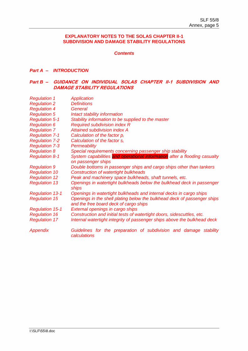
2. In cases where the operational trim range is intended to exceed ±0.5% of Ls, the original GM limit line should be designed in the usual manner with the deepest subdivision draught and partial subdivision draught calculated at level trim and actual service trim used for the light service draught. Then additional sets of GM limit lines should be constructed on the basis of the operational range of trims which is covered by loading conditions for each of the three draughts ds, dp and dl of partial subdivision draught and deepest subdivision draught ensuring that intervals of 1% Ls are not exceeded. For the light service draught dl only one trim is to be considered. The sets of GM limit lines are combined to give one envelope limiting GM curve. The effective trim range of the curve should be clearly stated. 3 If multiple GM limiting curves are obtained from damage stability calculations of differing trims in accordance with regulation 7, an envelope curve covering all calculated trim values should be developed. Calculations covering different trim values should be carried out in steps not exceeding 1% of Ls. The whole range including intermediate trims should be covered by the damage stability calculations. Refer to the example showing an envelope curve obtained from calculations of 0 trim and 1% of Ls.
4 As an alternative to an envelope curve, the calculations for additional trims may be carried out with one common GM for all of the trims assumed at [the deepest][each] subdivision draught [ds and the partial subdivision draught dp respectively]. The lowest values of each partial index As [and][,] Ap [and Al] across [these] trims will then be used in the summation of the attained subdivision index A according to regulation 7.1. [At the light service draught the partial index Al is assumed constant]. This will result in one GM limit curve based on the GM used at each draught. A trim [limit] [envelope] diagram showing the assumed trim range is then developed as shown in the figure.

SLF 55/8 Annex, page 24
I:\SLF\55\8.doc
[Replace the above figure:
[5 For a set of calculations the difference between trim values for ds, dp [and dl] may not exceed 1% Ls. It is not required that the trim values at ds, dp [and dl] coincide as long as the limitations with respect to variation between trims are observed at each draught. The applicable trim limits may then be marked at 0.5% Ls [L] in excess of the largest calculated trims as shown in the figure. There will be no trim limits in the draught range between dl and dp unless the limiting GM is governed by other applicable intact or damage stability criteria.] 6 Temporary loading conditions, e.g. due to ballast water exchange requirements, may occur with a draught less than dl. In this case, for draughts below dl the GM limit value of dl is to be used to comply with the damage stability requirements. 7 Ships may be permitted to sail at draughts above the subdivision draught ds according ILLC, e.g. using the tropical freeboard or the freshwater allowance. In this case, for draughts above ds the GM limit value of ds is to be used to comply with the damage stability requirements. Regulation 6 Required subdivision index R* 1 The subdivision of a ship is considered sufficient if the attained subdivision index A, determined in accordance with regulation 7, is not less than the required subdivision index R calculated in accordance with this regulation and if, in addition, the partial indices As, Ap and Al are not less than 0.9R for passenger ships and 0.5R for cargo ships.
______________ The Maritime Safety Committee, in adopting the regulations contained in parts B to B-4, invited
Administrations to note that the regulations should be applied in conjunction with the explanatory notes developed by the Organization in order to ensure their uniform application.
Trim Limit Diagram
0.5%Ls 0.5%Ls 0.5%Ls 0.5%Ls

SLF 55/8 Annex, page 25
I:\SLF\55\8.doc
Regulation 6.1 To demonstrate compliance with these provisions, see the Guidelines for the preparation of subdivision and damage stability calculations, set out in the appendix, regarding the presentation of damage stability calculation results. 2 For all ships to which the damage stability requirements of this chapter apply, the degree of subdivision to be provided shall be determined by the required subdivision index R, as follows:
.1 In the case of cargo ships greater than 100 m in length (Ls):
.2 In the case of cargo ships not less than 80 m in length (Ls) and not greater
than 100 m in length (Ls):
where Ro is the value R as calculated in accordance with the formula in
subparagraph .1.
.3 In the case of passenger ships:
where:
N = N1 + 2N2
N1 = number of persons for whom lifeboats are provided
N2 = number of persons (including officers and crew) the ship is
permitted to carry in excess of N1.
.4 Where the conditions of service are such that compliance with paragraph 2.3
of this regulation on the basis of N = N1+ 2N2 is impracticable and where the
Administration considers that a suitably reduced degree of hazard exists, a
lesser value of N may be taken but in no case less than N = N1 + N2 Regulation 6.2.4 Regarding the term "reduced degree of hazard", the following interpretation should be applied: A lesser value of N, but in no case less than N = N1 + N2, may be allowed at the discretion of the Administration for passenger ships, which, in the course of their voyages, do not proceed more than 20 miles from the nearest land.

SLF 55/8 Annex, page 26
I:\SLF\55\8.doc
Regulation 7
Attained subdivision index A
1 The attained subdivision index A is obtained by the summation of the partial indices
As, Ap and Al, (weighted as shown) calculated for the draughts ds, dp and dl defined in
regulation 2 in accordance with the following formula:
A = 0.4As + 0.4Ap + 0.2Al
Each partial index is a summation of contributions from all damage cases taken in
consideration, using the following formula: A = Σ pi si
where:
i represents each compartment or group of compartments under
consideration, pi accounts for the probability that only the compartment or group of
compartments under consideration may be flooded, disregarding any horizontal subdivision, as defined in regulation 7-1,
si accounts for the probability of survival after flooding the compartment or
group of compartments under consideration, and includes the effect of any horizontal subdivision, as defined in regulation 7-2.
Regulation 7.1
1. The probability of surviving after collision damage to the ship hull is expressed by
the index A. Producing an index A requires calculation of various damage scenarios defined
by the extent of damage and the initial loading conditions of the ship before damage. Three
loading conditions should be considered and the result weighted as follows: A = 0.4As + 0.4Ap + 0.2Al
where the indices s, p and l represent the three loading conditions and the factor to be
multiplied to the index indicates how the index A from each loading condition is weighted. 2. The method of calculating the A for a loading condition is expressed by the formula:
i=t
Ac = ∑ pi [vi si]
i=1
2.1 The index c represents one of the three loading conditions; index i represents each
investigated damage or group of damages and t is the number of damages to be investigated
to calculate Ac for the particular loading condition. 2.2 To obtain a maximum index a for a given subdivision, t has to be equal to T, the total number of damages.

SLF 55/8 Annex, page 27
I:\SLF\55\8.doc
3. In practice, the damage combinations to be considered are limited either by significantly reduced contributions to A (i.e. flooding of substantially larger volumes) or by exceeding the maximum possible damage length. 4. The index A is divided into partial factors as follows: pi The p factor is solely dependent on the geometry of the watertight
arrangement of the ship. vi The v factor is dependent on the geometry of the watertight arrangement
(decks) of the ship and the draught of the initial loading condition. It represents the probability that the spaces above the horizontal subdivision will not be flooded.
si The s factor is dependent on the calculated survivability of the ship after the
considered damage for a specific initial condition. 5. Three initial loading conditions should be used for calculating the index A. The loading conditions are defined by their mean draught d, trim and GM (or KG). The mean draught and trim are illustrated in the figure below.
6. The GM (or KG) values for the three loading conditions could, as a first attempt, be
taken from the intact stability GM (or KG) limit curve. If the required index R is not obtained,
the GM (or KG) values may be increased (or reduced), implying that the intact loading
conditions from the intact stability book must now meet the GM (or KG) limit curve from the
damage stability calculations derived by linear interpolation between the three GMs. 2 In the calculation of A, the level trim shall be used for the deepest subdivision draught and the partial subdivision draught. The actual service trim shall be used for the light service draught. If in any service condition, the trim variation in comparison with the calculated trim is greater than 0.5% of Ls, one or more additional calculations of A are to be submitted for the same draughts but different trims so that, for all service conditions, the difference in trim in comparison with the reference trim used for one calculation will be less than 0.5% of Ls. Regulation 7.2 1. The calculations for differing trim should be carried out with the same initial trim for the partial and deepest subdivision draughts. For the light service draught, the actual service trim should be used (refer to the Explanatory Notes for regulation 2.11). 2. Each combination of the index within the formula given in regulation 7.1 should not be less than the requirement given in regulation 6.2. Each partial index A should comply with the requirements of regulation 6.1.

SLF 55/8 Annex, page 28
I:\SLF\55\8.doc
3. Example: Based on the GM limiting curves obtained from damage stability calculations of each trim, an envelope curve covering all calculated trim values should be developed. Calculations covering different trim values should be carried out in steps not exceeding 1% of Ls. The whole range including intermediate trims should be covered by the damage stability calculations. Refer to the example showing an envelope curve obtained from calculations of 0 trim and 1% of Ls.
3 When determining the positive righting lever (GZ) of the residual stability curve in the final stage of flooding, [Q27B] the displacement used should be that of the intact condition. That is, the constant -displacement method of calculation should be used. Regulation 7.3 During For intermediate phases of flooding (see regulation 7-2.2 with Explanatory Notes and regulation 7-2.5.4), [Q27D(1)- 11-0 unanimous vote in favour of change]the added weight method is used and only one free surface needs to be assumed for water in spaces flooded during the current stage. In the final phase (full phase) of each stage the [lost buoyancy] [constant displacement] method is used, so one free surface is assumed for all flooded spaces. [In both cases, GZ is referred to the intact displacement]. [Q27D(2)] [Should we allow for multiple free surfaces – opinion divided 5 "Yes" 6 "No."] [Q27D(3)]
4 The summation indicated by the above formula shall be taken over the ship's subdivision length (Ls) for all cases of flooding in which a single compartment or two or more adjacent compartments are involved. In the case of unsymmetrical arrangements, the calculated A value should be the mean value obtained from calculations involving both sides. Alternatively, it should be taken as that corresponding to the side which evidently gives the least favourable result. 5 Wherever wing compartments are fitted, contribution to the summation indicated by the formula shall be taken for all cases of flooding in which wing compartments are involved. Additionally, cases of simultaneous flooding of a wing compartment or group of compartments and the adjacent inboard compartment or group of compartments, but excluding damage of transverse extent greater than one half of the ship breadth B, may be
SLF 55/8 Annex, page 29
I:\SLF\55\8.doc
added. For the purpose of this regulation, transverse extent is measured inboard from ship's side, at right angle to the centreline at the level of the deepest subdivision draught. Regulation 7.5 1. With the same intent as wing tanks, the summation of the attained index A should reflect effects caused by all watertight bulkheads and flooding boundaries within the damaged zone. It is not correct to assume damage only [to the centreline] to one half of the ship breadth B [CLIA Q2 – Coordinator's Note: This agreed change was omitted as an error from Round 6 document] and ignore changes in subdivision that would reflect lesser contributions. 2. In the forward and aft ends of the ship where the sectional breadth is less than the ship's breadth B, transverse damage penetration can extend beyond the centreline bulkhead. This application of the transverse extent of damage is consistent with the methodology to account for the localized statistics which are normalized on the greatest moulded breadth B rather than the local breadth. Where longitudinal corrugated bulkheads are fitted in wing compartments or on the centreline, they may be treated as equivalent plane bulkheads provided the corrugation depth is of the same order as the stiffening structure. The same principle may also be applied to transverse corrugated bulkheads. 6 In the flooding calculations carried out according to the regulations, only one breach of the hull and only one free surface need to be assumed in the final stage of flooding [Q27B]. The assumed vertical extent of damage is to extend from the baseline upwards to any watertight horizontal subdivision above the waterline or higher. However, if a lesser extent of damage will give a more severe result, such extent is to be assumed. [Should anything be added here on multiple free surfaces?] [Q27D(3) see regulation 7.3 of the EN] 7 If pipes, ducts or tunnels are situated within the assumed extent of damage, arrangements are to be made to ensure that progressive flooding cannot thereby extend to compartments other than those assumed flooded. However, the Administration may permit minor progressive flooding if it is demonstrated that its effects can be easily controlled and the safety of the ship is not impaired. Regulation 7.7
[1. Pipes and valves directly adjacent to a bulkhead or to a deck can be considered to
be part of the bulkhead or deck, provided the separation distance is of the same order as the
bulkhead or deck stiffening structure. The same applies for small recesses, drain wells, etc.]
[Coordinator's Note: The changes to regulation 7.7, EN1, in grey below were agreed at
SLF 53. There is a new proposal to harmonize the text with regulation 7-1.1.1, EN7, and
regulation 7-1.1.2, EN 12, as highlighted in green, below [CLIA Q6D – majority agree but
the United States has reservations, RINA opposed. To be discussed at SLF 54]:
1. Pipes and valves directly adjacent to a bulkhead or to a deck can be considered to
be part of the bulkhead or deck, provided the separation distance on either side of the
bulkhead or deck is of the same order as the bulkhead or deck stiffening structure. The same
applies for small recesses, drain wells, etc.

SLF 55/8 Annex, page 30
I:\SLF\55\8.doc
Valves which are situated as close as practicable to the bulkhead or deck, but exceeding due
to their in size the order depth of the stiffening structure should still be assumed to be part of
the bulkhead or deck.]
[2. The provision for allowing "minor progressive flooding" should be limited to
pipes penetrating a watertight subdivision with a total cross-sectional area of not more
than 710 mm2 between any two watertight compartments.]
[Coordinator's Note: There are two proposals for replacing regulation 7.7 EN2 [CLIA Q4D
majority favour option 2 but there are reservations – RINA, Germany, Norway and
France. Discuss at SLF 54]:-
OPTION 1:
2. The provision for allowing "minor progressive flooding" should be limited to pipes
penetrating a watertight subdivision with a total cross-sectional area of not more than [an
equivalent pipe diameter of Ls/5000] between any two watertight compartments. [The total
area of such pipes should be as small as practicable, taking into account the position of the
pipes and the size and location of the room.]
OPTION 2:
[2. For ships up to Ls = 150 m the provision for allowing "minor progressive flooding" should be limited to pipes penetrating a watertight subdivision with a total cross-sectional area of not more than 710 mm2 between any two watertight compartments. For ships of Ls = 350 m and upwards the provision for allowing "minor progressive flooding" should be limited to pipes penetrating a watertight subdivision with a total cross-sectional area of not more than 25500 mm2 between any two watertight compartments. For ships between Ls = 150 and 350 m, the total cross-sectional area should be obtained by linear interpolation between the above figures. For ships of Ls = 150 m and upwards no individual pipe should exceed a diameter of Ls/5000 m].] Regulation 7-1 Calculation of the factor pi General 1. The definitions below are intended to be used for the application of part B-1 only. 2. In regulation 7-1, the words "compartment" and "group of compartments" should be understood to mean "zone" and "adjacent zones".
3. Zone – a longitudinal interval of the ship within the subdivision length.
4. Room – a part of the ship, limited by bulkheads and decks, having a specific permeability. 5. Space – a combination of rooms.

SLF 55/8 Annex, page 31
I:\SLF\55\8.doc
6. Compartment – an onboard space within watertight boundaries. 7. Damage – the three dimensional extent of the breach in the ship. 8. For the calculation of p, v, r and b only the damage should be considered, for the calculation of the s-value the flooded space should be considered. The figures below illustrate the difference. Damage shown as the bold square: Flooded space shown below:

SLF 55/8 Annex, page 32
I:\SLF\55\8.doc
[Q28] (Coordinator's Note:- Sorry - unable to edit above .pdf file!]

SLF 55/8 Annex, page 33
I:\SLF\55\8.doc

SLF 55/8 Annex, page 34
I:\SLF\55\8.doc

SLF 55/8 Annex, page 35
I:\SLF\55\8.doc
Regulation 7-1.1.1 1. The coefficients b11, b12, b21 and b22 are coefficients in the bi-linear probability density function on normalized damage length (J). The coefficient b12 is dependent on whether Ls is greater or less than L* (i.e. 260 m); the other coefficients are valid irrespective of Ls. Longitudinal subdivision 2. In order to prepare for the calculation of index A, the ship's subdivision length Ls is divided into a fixed discrete number of damage zones. These damage zones will determine the damage stability investigation in the way of specific damages to be calculated. 3. There are no rules for the subdividing, except that the length Ls defines the extremes for the actual hull. Zone boundaries need not coincide with physical watertight boundaries. However, it is important to consider a strategy carefully to obtain a good result (that is a large attained index A). All zones and combination of adjacent zones may contribute to the index A. In general it is expected that the more zone boundaries the ship is divided into the higher will be the attained index, but this benefit must be balanced against extra computing time. The figure below shows different longitudinal zone divisions of the length Ls.
4. The first example is a very rough division into three zones of approximately the same size with limits where longitudinal subdivision is established. The probability that the ship will survive a damage in one of the three zones is expected to be low (i.e. the s-factor is low or zero) and, therefore, the total attained index A will be correspondingly low. 5. In the second example the zones have been placed in accordance with the watertight arrangement, including minor subdivision (as in double bottom, etc.). In this case there is a much better chance of obtaining higher s-factors.
6. Where transverse corrugated bulkheads are fitted, they may be treated as equivalent
plane bulkheads, provided the corrugation depth is of the same order as the stiffening
structure.

SLF 55/8 Annex, page 36
I:\SLF\55\8.doc
[7. Pipes and valves directly adjacent to a transverse bulkhead can be considered to be
part of the bulkhead, provided the separation distance is of the same order as the bulkhead
stiffening structure. The same applies for small recesses, drain wells, etc.]
[Coordinator's Note:. There is a new proposal to harmonize the text with regulation 7.7,
EN1, and regulation 7-1.1.2, EN 12, as highlighted in green, below [CLIA Q6D]:-
7. Pipes and valves directly adjacent to a transverse bulkhead or to a deck can be
considered to be part of the bulkhead or deck, provided the separation distance on either
side of the bulkhead or deck is of the same order as the bulkhead or deck stiffening
structure. The same applies for small recesses, drain wells, etc.]
8. For cases where the pipes and valves are outside the transverse bulkhead stiffening
structure, when they present a risk of progressive flooding to other watertight compartments
that will have influence on the overall attained index A, they should be handled either by
introducing a new damage zone and accounting for the progressive flooding to associated
compartments or by introducing a gap.
9. The triangle in the figure below illustrates the possible single and multiple zone
damages in a ship with a watertight arrangement suitable for a seven-zone division. The
triangles at the bottom line indicate single zone damages and the parallelograms indicate
adjacent zones damages.
Z 1 Z2 Z3 Z4 Z5 Z6 Z7

SLF 55/8 Annex, page 37
I:\SLF\55\8.doc
10. As an example, the triangle illustrates a damage opening the rooms in zone 2 to the sea and the parallelogram illustrates a damage where rooms in zones 4, 5 and 6 are flooded simultaneously. 11. The shaded area illustrates the effect of the maximum absolute damage length. The p-factor for a combination of three or more adjacent zones equals zero if the length of the combined adjacent damage zones minus the length of the foremost and the aft most damage zones in the combined damage zone is greater than the maximum damage length. Having this in mind when subdividing Ls could limit the number of zones defined to maximize the attained index A. 12. As the p-factor is related to the watertight arrangement by the longitudinal limits of damage zones and the transverse distance from the ship side to any longitudinal barrier in the zone, the following indices are introduced:

SLF 55/8 Annex, page 38
I:\SLF\55\8.doc

SLF 55/8 Annex, page 39
I:\SLF\55\8.doc
[Q29][ Issues of raking damage and structural resistance to be discussed after SLF54] Regulation 7-1.1.2 Transverse subdivision in a damage zone
1. Damage to the hull in a specific damage zone may just penetrate the ship's
watertight hull or penetrate further towards the centreline. To describe the probability of
penetrating only a wing compartment, a probability factor r is used, based mainly on the

SLF 55/8 Annex, page 40
I:\SLF\55\8.doc
penetration depth b. The value of r is equal to 1, if the penetration depth is B/2 where B is the
maximum breadth of the ship at the deepest subdivision draught ds, and r = 0 if b = 0.
2. The penetration depth b is measured at level deepest subdivision draught ds as a
transverse distance from the ship side right-angled to the centreline to a longitudinal barrier.
3. Where the actual watertight bulkhead is not a plane parallel to the shell, b should be
determined by means of an assumed line, dividing the zone to the shell in a relationship
b1/b2 with
4. Examples of such assumed division lines are illustrated in the figure below. Each
sketch represents a single damage zone at a water line plane level ds and the longitudinal
bulkhead represents the outermost bulkhead position below ds + 12.5 m.

SLF 55/8 Annex, page 41
I:\SLF\55\8.doc
TRANSVERSE SUBDIVISION INTERCEPTING THE HULL [Can we accept these new diagrams and text?] [Q30D. 9-2 in favour but the United States want refinement; the United Kingdom opposes 4.1; France has problems]
4.1 If a transverse subdivision intercepts the deepest subdivision draught waterline within the extent of the zone, b is equal to zero (0) in that zone for the transverse subdivision in question, see figures 1 and 2.
Figure 1 Figure 2 In the above illustrated cases b differing from zero (0) can be obtained by moving the aft limit of the zone according to figure 3 or by including an additional zone according to figure 4.
Figure 3 Figure 4 Part of the waterline including multiple coordinates 4.2 If the deepest external subdivision draught waterline on the studied side of a single hull ship includes a part where multiple transversal (y) coordinates occur for a longitudinal (x) location, a straightened reference waterline can be used for the calculation of b. If this approach is chosen, the original waterline is replaced by an envelope curve including straight parts perpendicular to the centreline where multiple transversal coordinates occur, see figures 1 to 4. The maximum transverse damage extent B/2 is then also calculated from the reference waterline.

SLF 55/8 Annex, page 42
I:\SLF\55\8.doc
Figure 1 Figure 2
Figure 3 Figure 4 [Q30D - end]

SLF 55/8 Annex, page 43
I:\SLF\55\8.doc

SLF 55/8 Annex, page 44
I:\SLF\55\8.doc
10. A damage giving a transverse extent b and a vertical extent H2 leads to the flooding
of both wing compartment and hold; for b and H1 only the wing compartment is flooded. The
figure below illustrates a partial subdivision draught dp damage.

SLF 55/8 Annex, page 45
I:\SLF\55\8.doc
11. The same is valid if b-values are calculated for arrangements with sloped walls. [CLIA Q5D] [Can we now accept the following revised diagram and proposed text? This would, if accepted, presumably be new EN 12] [11-0 in favour but the United States would prefer it as EN2 for regulation 7.5; the United Kingdom wants to replace "penetration b" with "penetration b/2"]:- 12. Where at the extreme ends of the ship the subdivision exceeds the waterline at the deepest subdivision draught, the damage penetration b or B/2 is to be taken from centre line. The following figure illustrates the shape of the B/2 line:

SLF 55/8 Annex, page 46
I:\SLF\55\8.doc
[12. Pipes and valves directly adjacent to a longitudinal bulkhead can be considered to be part of the bulkhead, provided the separation distance is of the same order as the bulkhead stiffening structure. The same applies for small recesses, drain wells, etc.]
[Coordinator's Note: The changes to regulation 7-1.1.2, EN12, in grey below were agreed
at SLF 53. There is a new proposal to harmonize the text with regulation 7.7, EN1, and
regulation 7-1.1.1, EN 7, as highlighted in green, below. Note that the word "longitudinal" was
in the original EN but had been removed. It is now proposed to restore it. [CLIA Q6D.
Majority in favour but RINA, Norway, the United States and France have reservations]:-
[12][13]. Pipes and valves directly adjacent to a longitudinal bulkhead or to a deck can be
considered to be part of the bulkhead or deck, provided the separation distance on either
side of the bulkhead or deck is of the same order as the bulkhead or deck stiffening
structure. The same applies for small recesses, drain wells, etc. Valves which are situated as close as practicable to the bulkhead or deck, but exceeding due to their in size the order depth of the stiffening structure should still be assumed to be part of the bulkhead or deck.]
Regulation 7-2
Calculation of the factor si
General 1. Initial condition – an intact loading condition to be considered in the damage analysis described by the mean draught, vertical centre of gravity and the trim. Or alternative parameters from which the same may be determined (e.g. displacement, GM and trim). There are three initial conditions corresponding to the three draughts ds, dp and dl. 2. Immersion limits – immersion limits are an array of points that are not to be immersed at various stages of flooding as indicated in regulations 7-2.5.2 and 7-2.5.3. 3. Openings – all openings need to be defined: both weathertight and unprotected. Openings are the most critical factor to preventing an inaccurate index A. If the final waterline immerses the lower edge of any opening through which progressive flooding takes place, the factor "s" may be recalculated taking such flooding into account. However, in this case the s value should also be calculated without taking into account progressive flooding and corresponding opening. The smallest s value should be retained for the contribution to the attained index. 1 The factor si shall be determined for each case of assumed flooding, involving a compartment or group of compartments, in accordance with the following notations and the provisions in this regulation.
ᶿe is the equilibrium heel angle in any stage of flooding, in degrees;
ᶿv is the angle, in any stage of flooding, where the righting lever becomes negative,
or the angle at which an opening incapable of being closed weathertight becomes submerged;
GZmax is the maximum positive righting lever, in metres, up to the angle ᶿv;
Range is the range of positive righting levers, in degrees, measured from the angle
ᶿe. The positive range is to be taken up to the angle ᶿv;

SLF 55/8 Annex, page 47
I:\SLF\55\8.doc
Flooding stage is any discrete step during the flooding process, including the stage before equalization (if any) until final equilibrium has been reached.
Regulation 7-2.1 1. In cases where the GZ curve may include more than one "range" of positive righting levers for a specific stage of flooding, only one continuous positive "range" of the GZ curve may be used within the allowable range/heel limits for calculation purposes. Different stages of flooding may not be combined in a single GZ curve.
2. In figure 1, the s-factor may be calculated from the heel angle, range and
corresponding GZmax of the first or second "range" of positive righting levers. In figure 2, only
one s-factor can be calculated.
1.1 The factor si, for any damage case at any initial loading condition, di, shall be
obtained from the formula: si = minimum { sintermediate,i or sfinal,i x smom,i }
where:
sintermediate,i is the probability to survive all intermediate flooding stages until the final
equilibrium stage, and is calculated in accordance with paragraph 2;
sfinal,i is the probability to survive in the final equilibrium stage of flooding. It is
calculated in accordance with paragraph 3;
smom,i is the probability to survive heeling moments, and is calculated in accordance
with paragraph 4.

SLF 55/8 Annex, page 48
I:\SLF\55\8.doc
[2 The factor sintermediate,i is applicable only to passenger ships (for cargo ships sintermediate,i
should be taken as unity) and shall be taken as the least of the s-factors obtained from all
flooding stages including the stage before equalization, if any, and is to be calculated as
follows:
where GZmax is not to be taken as more than 0.05 m and Range as not more than 7°.
sintermediate = 0, if the intermediate heel angle exceeds 15º. Where cross-flooding fittings are
required, the time for equalization shall not exceed 10 min.]
[Q31D] [France has proposed that "sintermediate" should vary progressively as a function of
heel. Therefore the proposal would be to have a K factor as for "s final"]:
where:
Kint =
For final equilibrium θmax is of 15 degrees compared to 12 degrees in present SOLAS. For
intermediate stages, maximum angle of 15 degrees would give a θmax of 18.75 degrees.
Proposed values may be:
θmin-int = 10 degrees θmax-int = 18 degrees
[Note that France is now proposing to change θmin-int from 10 to 12 degrees.] [The question is, should we delay any action on this until the results of further work on the "s-factor" become available? [CG voted 13-1 in favour of this; the United States opposes] [Q32D] Norway has proposed that regulation 7-2.2 should take more account of IS flooding on cargo ships. We have a revised text for this change but Norway has been asked to clarify the proposal as support is not unanimous. The current revised text is]:-
2 For passenger ships the factor sintermediate,i is taken as the least of the s-factors
obtained from all flooding stages including the stage before equalization, if any, and is
to be calculated as follows:
where GZmax is not to be taken as more than 0.05 m and Range as not more than 7°.
sintermediate,i = 0, if the intermediate heel angle exceeds 15º. For cargo ships the factor sintermediate,i is taken as unity, except in those cases where it is [found] [anticipated] that the ship would [capsize and sink] during the intermediate stages, in which case sintermediate,I is taken as 0.
SLF 55/8 Annex, page 49
I:\SLF\55\8.doc
[For passenger and cargo ships], where cross-flooding fittings are required, the time for
equalization shall not exceed 10 min.] [Q32D; 9-2 in favour of Norway producing new text; Germany and China oppose; Norway and US have comments. Discuss at SLF 54] [How we answer this question could also affect the EN (originally reg. 7-2.2 EN 9) for cargo ship IS flooding.] [Q34] Regulation 7-2.2 Intermediate stages of flooding 1. The case of instantaneous flooding in unrestricted spaces in way of the damage zone does not require intermediate stage flooding calculations. Where intermediate stages of flooding calculations are necessary in connection with progressive flooding, or flooding through non-watertight boundaries [CLIA Q7] they should reflect the sequence of filling as well as filling level phases. Calculations for intermediate stages of flooding should be performed whenever equalization is not instantaneous, i.e. equalization is of a duration greater than 60 s. Such calculations consider the progress through one or more floodable (non-watertight) spaces. Bulkheads surrounding refrigerated spaces, incinerator rooms and longitudinal bulkheads fitted with non-watertight doors are typical examples of structures that may significantly slow down the equalization of main compartments. Flooding boundaries 2. If a compartment contains decks, inner bulkheads, structural elements and doors of sufficient tightness and strength to seriously restrict the flow of water, for intermediate stage flooding calculation purposes it should be divided into corresponding non-watertight spaces. It is assumed that the non-watertight divisions considered in the calculations are limited to "A" class fire-rated bulkheads and do not apply to "B" class fire-rated bulkheads normally used in accommodation areas (e.g. cabins and corridors). This guidance also relates to regulation 4.4. For spaces in the double bottom in general only main longitudinal structures with a limited number of openings have to be considered as flooding boundaries. [CLIA Q8] Sequential flooding computation 3. For each damage scenario, the damage extent and location determine the initial stage of flooding. Calculations should be performed in stages, each stage comprising of at least two intermediate filling phases in addition to the full phase per flooded space. Unrestricted spaces in way of damage should be considered as flooded immediately. Every subsequent stage involves all connected spaces being flooded simultaneously until an impermeable boundary or final equilibrium is reached. If due to the configuration of the subdivision in the ship it is expected that other intermediate stages of flooding are more onerous, then those should be investigated. Cross-flooding/equalization 4. [In general, cross-flooding is meant as a flooding of an undamaged space on the other side of the ship to reduce the heel in the final equilibrium condition]. In general, cross-flooding is used to reduce heel in the final equilibrium [situation] [stage of flooding] in order to improve survivability following [asymmetrical] damage. It is achieved by allowing flood water to cross into an undamaged watertight space on the other side of the ship through a special device such as a pipe or duct. Typical examples of such cross-flooding devices are shown below where the after wing tanks are connected via a cross-flooding pipe and the forward double bottom wing void spaces are connected via a cross-flooding duct. [CLIA Q10D(1)][Do we accept the new changes in green? The changes

SLF 55/8 Annex, page 50
I:\SLF\55\8.doc
in grey and the diagram below were accepted at SLF 53. Will the diagram be clear when printed in black and white?] [Voting 11-2 in favour of changes in green; Italy and China oppose; France has comments; discuss at SLF 54.]
5. The cross-flooding time should be calculated in accordance with the Recommendation on a standard method for evaluating cross-flooding arrangements (resolution MSC.245(83)) [with the commencement of the cross-flooding time being when the damaged spaces are assumed to be filled to the outside water level but the cross-flooding device is empty]. [Q33D(2); 7 support this] If complete fluid equalization occurs in 60 s or less, it should be treated as instantaneous and no further calculations need to be carried out. Additionally, in cases where sfinal = 1 is achieved in 60 s or less, but equalization is not complete, instantaneous flooding may also be assumed if sfinal will not become reduced. In any cases where complete fluid equalization exceeds 60 s, the value of sintermediate after 60 s is the first intermediate stage to be considered. Only passive open cross-flooding arrangements without valves should be considered effective for instantaneous flooding cases. [Coordinator's Note: linked to this is the question of possible changes to resolution MSC.245(83), in particular the cross-flooding figures and whether the cross-flooding pipe/duct should be assumed to be flooded instantaneously [Q33D(1) (7 in favour 3 against);(3)(7 support) (4) (11-1 in favour] and France's proposal to treat cross-flooding ducts as rooms [Q33D(5); 2 support, 8 against].
[6. If complete fluid equalization can be finalized in 10 min or less, the assessment of
survivability can be carried out for passenger ships as the smallest values of sintermediate or
sfinal.
7. In case the equalization time is longer than 10 min, sfinal is calculated for the floating
position achieved after 10 min of equalization. This floating position is computed by
calculating the amount of flood water according to resolution MSC.245(83) using
interpolation, where the equalization time is set to 10 min, i.e. the interpolation of the flood
water volume is made between the case before equalization (T = 0) and the total calculated
equalization time.

SLF 55/8 Annex, page 51
I:\SLF\55\8.doc
8. In any cases where complete fluid equalization exceeds 10 min, the value of sfinal
used in the formula in paragraph 1.1 should be the minimum of sfinal at 10 min or at final
equalization.] [the United States propose to delete EN6 and merge EN7 and 8 Q67D; 7-3 in
favour; discuss.]
9. As an alternative to the procedure described above a time-domain flooding
simulation [,computational fluid dynamics (CFD) or model testing][CLIA Q10D(2); 10-1 in
favour; recommend change]may be carried out to assess the smallest values of [sintermediate
(for situations within 600s) or][the United States propose deletion, see Q33C] sfinal (for
situation after 600 s).
Cargo ships
[9][10]. If the Administration considers that the stability in intermediate stages of flooding in
a cargo ship may be [insufficient] [Q34 awaiting outcome of Q32D], it may require further
investigation thereof. [Need to discuss all these EN's together at SLF 54 once we agree
to Q32D.] 3 The factor sfinal,i shall be obtained from the formula:
where:
GZmax is not to be taken as more than 0.12 m;
Range is not to be taken as more than 16°;
4 The factor smom,i is applicable only to passenger ships (for cargo ships smom,i shall be
taken as unity) and shall be calculated at the final equilibrium from the formula:

SLF 55/8 Annex, page 52
I:\SLF\55\8.doc
where: Displacement is the intact displacement at the subdivision draught; Mheel is the maximum assumed heeling moment as calculated in accordance with subparagraph 4.1; and
Regulation 7-2.4 1. The displacement is the intact displacement at the subdivision draught in question (ds, dp and dl ). 2. The calculations should be based on the same hull form as for intact stability calculations (including appendages and shell plating). 3. The stability levers (GZ) and centre of gravity positions (KG) for judging the final survival conditions should be calculated by the constant displacement (lost buoyancy) method. 4. The calculations should be done for the ship freely trimming. [Q35]
4.1 The heeling moment Mheel is to be calculated as follows:
Mheel = maximum {Mpassenger or Mwind or MSurvivalcraft}
4.1.1 Mpassenger is the maximum assumed heeling moment resulting from movement of passengers, and is to be obtained as follows:
Mpassenger = (0.075 · Np) · (0.45 · B) (tm)
where:
Np is the maximum number of passengers permitted to be on board in the service condition corresponding to the deepest subdivision draught under consideration; and
B is the beam of the ship breadth of the ship as defined in regulation 2.8. [Q36]
Alternatively, the heeling moment may be calculated assuming the passengers are distributed with 4 persons per square metre on available deck areas towards one side of the ship on the decks where muster stations are located and in such a way that they produce the most adverse heeling moment. In doing so, a weight of 75 kg per passenger is to be assumed. Regulation 7-2.4.1.1 The beam B used in this paragraph means breadth as defined in regulation 2.8. [Q36] 4.1.2 Mwind is the maximum assumed wind force acting in a damage situation:
Mwind = (P · A · Z) / 9,806 (tm)

SLF 55/8 Annex, page 53
I:\SLF\55\8.doc
where:
P = 120 N/m2
; A = projected lateral area above waterline; Z = distance from centre of lateral projected area above waterline to T/2; and T = ship's draught, di.
Regulation 7-2.4.1.2
The parameter A (projected lateral area) used in this paragraph does not refer to the attained subdivision index. 4.1.3 MSurvivalcraft is the maximum assumed heeling moment due to the launching of all fully loaded davit-launched survival craft on one side of the ship. It shall be calculated using the following assumptions:
.1 all lifeboats and rescue boats fitted on the side to which the ship has heeled
after having sustained damage shall be assumed to be swung out fully loaded and ready for lowering;
.2 for lifeboats which are arranged to be launched fully loaded from the
stowed position, the maximum heeling moment during launching shall be taken;
.3 a fully loaded davit-launched liferaft attached to each davit on the side to
which the ship has heeled after having sustained damage shall be assumed to be swung out ready for lowering;
.4 persons not in the life-saving appliances which are swung out shall not
provide either additional heeling or righting moment; and .5 life-saving appliances on the side of the ship opposite to the side to which
the ship has heeled shall be assumed to be in a stowed position. 5 Unsymmetrical flooding is to be kept to a minimum consistent with the efficient arrangements. Where it is necessary to correct large angles of heel, the means adopted shall, where practicable, be self-acting, but in any case where controls to equalization devices are provided they shall be operable from above the bulkhead deck. These fittings together with their controls shall be acceptable to the Administration*. Suitable information concerning the use of equalization devices shall be supplied to the master of the ship. Regulation 7-2.5 In cargo ships where cross flooding devices are fitted, the safety of the ship should be maintained in all stages of flooding. The Administration may request for this to be demonstrated. Cross-flooding equipment, if installed, should have the capacity to ensure that the equalization takes place within 10 min.

SLF 55/8 Annex, page 54
I:\SLF\55\8.doc
5.1 Tanks and compartments taking part in such equalization shall be fitted with air
pipes or equivalent means of sufficient cross-section to ensure that the flow of water into the equalization compartments is not delayed.
_____________ * Reference is made to the Recommendation on a standard method for [establishing compliance
with the requirements for] [evaluating] cross-flooding arrangements [in passengers ships], adopted by the Organization by resolution [A.266(VIII)] [MSC.245(83), as may be amended].
5.2 In all cases, si is to be taken as zero in those cases where the final waterline, taking into account sinkage, heel and trim, immerses:
.1 the lower edge of openings through which progressive flooding may take
place and such flooding is not accounted for in the calculation of factor si.
Such openings shall include air-pipes, ventilators and openings which are
closed by means of weathertight doors or hatch covers; and
Regulation 7-2.5.2.1 Unprotected openings 1. The flooding angle will be limited by immersion of such an opening. It is not necessary to define a criterion for non-immersion of unprotected openings at equilibrium, because if it is immersed, the range of positive GZ limited to flooding angle will be zero so "s" will be equal to zero. 2. An unprotected opening connects two rooms or one room and the outside. An unprotected opening will not be taken into account if the two connected rooms are flooded or none of these rooms are flooded. If the opening is connected to the outside, it will not be taken into account if the connected compartment is flooded. An unprotected opening does not need to be taken into account if it connects a flooded room or the outside to an undamaged room, if this room will be considered as flooded in a subsequent stage. Openings fitted with a weathertight mean of closing ("weathertight openings") 3. The survival "s" factor will be "0" if any such point is submerged at a stage which is considered as "final". Such points may be submerged during a stage or phase which is considered as "intermediate", or within the range beyond equilibrium. 4. If an opening fitted with a weathertight means of closure is submerged at equilibrium during a stage considered as intermediate, it should be demonstrated that this weathertight means of closure can sustain the corresponding head of water and that the leakage rate is negligible. 5. These points are also defined as connecting two rooms or one room and the outside, and the same principle as for unprotected openings is applied to take them into account or not. If several stages have to be considered as "final", a "weathertight opening" does not need to be taken into account if it connects a flooded room or the outside to an undamaged room if this room will be considered as flooded in a successive "final" stage.
.2 any part of the bulkhead deck in passenger ships considered a horizontal
evacuation route for compliance with chapter II-2. [Q37D – see below]

SLF 55/8 Annex, page 55
I:\SLF\55\8.doc
Regulation 7-2.5.2.2 1. Partial immersion of the bulkhead deck may be accepted at final equilibrium. This [new] [CLIA Q11 agreed to retain original text] provision is intended to ensure that evacuation along the bulkhead deck to the vertical escapes will not be impeded by water on that deck. A "horizontal evacuation route" in the context of this regulation means a route on the bulkhead deck connecting spaces located on and under this deck with the vertical escapes from the bulkhead deck required for compliance with SOLAS chapter II-2. 2. Horizontal evacuation routes on the bulkhead deck include only escape routes (designated as category 2 stairway spaces according to SOLAS regulation II-2/9.2.2.3 or as category 4 stairway spaces according to SOLAS regulation II-2/9.2.2.4 for passenger ships carrying not more than 36 passengers) used for the evacuation of undamaged spaces. Horizontal evacuation routes do not include corridors (designated as category 3 corridor spaces according to SOLAS regulation II-2/9.2.2.3 or as category 2 corridor spaces according to SOLAS regulation II-2/9.2.2.4 for passenger ships carrying not more than 36 passengers)) or escape routes within the damaged space. Landing areas and half landings of a staircase are part of the vertical escape way and not part of a horizontal escape route. [Q37D] [Coordinator's Note: the correspondence group in round 4 expressed some dissatisfaction with these EN changes which were agreed at SLF 53. Now we are awaiting responses to various options in the Round 6 questionnaire which may also involve changing the wording of the regulation itself. Discuss at SLF 54.] No part of a horizontal evacuation route serving undamaged spaces should be immersed.
3. si = 0 where it is not possible to access a stair leading up to the embarkation deck
from an undamaged space as a result of flooding to the "stairway" or "horizontal stairway" on
the bulkhead deck.
[4. Horizontal escapes situated in way of the damage extent may remain effective,
therefore si need not be taken as zero. Contributions to the attained index A may still be
gained.] [CLIA Q12] [Coordinator's Note: At SLF 53 it was agreed to replace the text of
EN4 with a new diagram and introductory text]:-

SLF 55/8 Annex, page 56
I:\SLF\55\8.doc
[Example for horizontal escape routes:
]
[Some correspondence group members are not in favour of deleting the original text so the
whole question of the EN's for regulation 7-2.5.2.2 is to be re-examined under Q37D.
Discuss at SLF 54.]
[.3 for ro-ro passenger ships, when damaged above the bulkhead deck, any
part of the bulkhead deck in way of the damage opening in which the
residual freeboard is less than [x] metres. [Coordinator's Note:– new
proposal to be discussed by the ro-ro correspondence group]]
5.3 The factor si is to be taken as zero if, taking into account sinkage, heel and trim, any
of the following occur in any intermediate stage or in the final stage of flooding:
.1 immersion of any vertical escape hatch in the bulkhead deck intended for
compliance with chapter II-2;
Regulation 7-2.5.3.1 1. The purpose of this paragraph is to provide an incentive to ensure that evacuation through a vertical escape will not be obstructed by water from above. The paragraph is intended for smaller emergency escapes, typically hatches, where fitting of a watertight or weathertight means of closure would otherwise exclude them from being considered as flooding points.

SLF 55/8 Annex, page 57
I:\SLF\55\8.doc
2. Since the probabilistic regulations do not require that the watertight bulkheads be carried continuously up to the bulkhead deck, care should be taken to ensure that evacuation from intact spaces through flooded spaces below the bulkhead deck will remain possible, for instance by means of a watertight trunk.
.2 any controls intended for the operation of watertight doors, equalization
devices, valves on piping or on ventilation ducts intended to maintain the
integrity of watertight bulkheads from above the bulkhead deck become
inaccessible or inoperable;
.3 immersion of any part of piping or ventilation ducts carried through a
watertight boundary that is located within any compartment included in
damage cases contributing to the attained index A, if not fitted with
watertight means of closure at each boundary.
.3 immersion of any part of piping or ventilation ducts [that is] located within
the assumed extent of damage and carried through a watertight boundary if
this can lead to the progressive flooding of compartments not assumed as
flooded. [CLIA Q13] 5.4 However, where compartments assumed flooded due to progressive flooding are taken into account in the damage stability calculations multiple values of sintermediate,i may be calculated assuming equalization in additional flooding phases. 5.5 Except as provided in paragraph 5.3.1, openings closed by means of watertight manhole covers and flush scuttles, small watertight hatch covers, remotely operated sliding watertight doors, side scuttles of the non-opening type as well as watertight access doors and hatch covers required to be kept closed at sea need not be considered. 6 Where horizontal watertight boundaries are fitted above the waterline under consideration the s-value calculated for the lower compartment or group of compartments shall be obtained by multiplying the value as determined in paragraph 1.1 by the reduction factor vm according to paragraph 6.1, which represents the probability that the spaces above the horizontal subdivision will not be flooded.

SLF 55/8 Annex, page 58
I:\SLF\55\8.doc
Regulation 7-2.6
The sketches in the figure illustrate the connection between position of watertight decks in
the reserve buoyancy area and the use of factor v for damages below these decks.

SLF 55/8 Annex, page 59
I:\SLF\55\8.doc
Regulation 7-2.6.1 The parameters x1 and x2 are the same as parameters x1 and x2 used in regulation 7-1.

SLF 55/8 Annex, page 60
I:\SLF\55\8.doc
Regulation 7-3
Permeability
1 For the purpose of the subdivision and damage stability calculations of the
regulations, the permeability of each general compartment or part of a compartment shall be
as follows:
Spaces Permeability
Appropriated to stores Occupied by accommodation Occupied by machinery Void spaces Intended for liquids
0.60 0.95 0.85 0.95
0 or 0.951
1 Whichever results in the more severe requirement.
2 For the purpose of the subdivision and damage stability calculations of the
regulations, the permeability of each cargo compartment or part of a compartment shall be
as follows:
Spaces Permeability at
draught ds Permeability at
draught dp Permeability at
draught dl
Dry cargo spaces Container spaces Ro-ro spaces Cargo liquids
0.70 0.70 0.90 0.70
0.80 0.80 0.90 0.80
0.95 0.95 0.95 0.95
Regulation 7-3.2 1. The following additional cargo permeabilities may be used:
Spaces Permeability at
draught ds Permeability at
draught dp Permeability at
draught dl
Timber cargo in holds 0.35 0.70 0.95
Wood chip cargo 0.60 0.70 0.95

SLF 55/8 Annex, page 61
I:\SLF\55\8.doc
2. Reference is made to MSC/Circ.998 (IACS Unified Interpretation regarding timber deck cargo in the context of damage stability requirements) regarding timber deck cargo (reproduced below).
3 Other figures for permeability may be used if substantiated by calculations. Regulation 7-3.3 1. Concerning the use of other figures for permeability "if substantiated by calculations", such permeabilities should reflect the general conditions of the ship throughout its service life rather than specific loading conditions. 2. This paragraph allows for the recalculation of permeabilities. This should only be considered in cases where it is evident that there is a major discrepancy between the values shown in the regulation and the real values. It is not designed for improving the attained value of a deficient ship of regular type by the modification of chosen spaces in the ship that are known to provide significantly onerous results. All proposals should be considered on a case-by-case basis by the Administration and should be justified with adequate calculations and arguments.
Regulation 8
Special requirements concerning passenger ship stability
EITHER (United States proposal to delete regulation 8.1):
[1 A passenger ship intended to carry 400 or more persons shall have watertight
subdivision abaft the collision bulkhead so that si = 1 for the three loading conditions on
which is based the calculation of the subdivision index and for a damage involving all the
compartments within 0.08L measured from the forward perpendicular.]
OR:-
[1 A passenger ship intended to carry 400 or more persons shall have watertight
subdivision abaft the collision bulkhead so that si = 1 for a damage involving all the
compartments within 0.08L measured from the forward perpendicular for the three loading
conditions upon which is based the calculation of [the] [a] subdivision index.] [Q39-41D] Regulation 8.1
The intention of this regulation is to prevent the fitting of a large compartment aft of the
collision bulkhead [Q39-41D – proposed new EN] [See also proposal for regulation 12.2] [(1)
There was voting of 13-1 against the United States proposal to delete regulation 8.1;
(2) 8-2 were in favour of Germany's proposal and (3) 9-2 were in favour of the
proposed bracket deletions in regulation 8.1 and new 12.2. Not unanimous, so discuss
at SLF 54].
2 A passenger ship intended to carry 36 or more persons is to be capable of
withstanding damage along the side shell to an extent specified in paragraph 3. Compliance
with this regulation is to be achieved by demonstrating that si, as defined in regulation 7-2, is
not less than 0.9 for the three loading conditions on which is based the calculation of the
subdivision index. If the subdivision index is calculated for different trims, this requirement
must also be satisfied for [these loading conditions][all loading conditions used for the
calculation of the subdivision [indexes][indices]]. [Q42D; Voting was 10-4 in favour of

SLF 55/8 Annex, page 62
I:\SLF\55\8.doc
France's proposed deletions and use of "indices" instead of "indexes". Discuss at
SLF 54.]
3 The damage extent to be assumed when demonstrating compliance with
paragraph 2, is to be dependent on both N as defined in regulation 6 the total number of
persons carried [Q43C], and Ls L [Q38] as defined in regulation 2 [Q43C], such that:
.1 the vertical extent of damage is to extend from the ship's moulded baseline to a position up to 12.5 m above the position of the deepest subdivision draught as defined in regulation 2, unless a lesser vertical extent of damage were to give a lower value of si, in which case this reduced extent is to be used;
.2 where 400 or more persons are to be carried, a damage length of 0.03 Ls L
[Q38], but not less than 3 m is to be assumed at any position along the side shell, in conjunction with a penetration inboard of 0.1B but not less than 0.75 m measured inboard form the ship side, at right angle to the centreline at the level of the deepest subdivision draught;
.3 where less than 400 persons are carried, damage length is to be assumed
at any position along the side shell between transverse watertight bulkheads provided that the distance between two adjacent transverse watertight bulkheads is not less than the assumed damage length. If the distance between adjacent transverse watertight bulkheads is less than the assumed damage length, only one of these bulkheads shall be considered effective for the purpose of demonstrating compliance with paragraph 2;
.4 where 36 persons are carried, a damage length of 0.015 Ls L [Q38] but not
less than 3 m is to be assumed, in conjunction with a penetration inboard of 0.05B but not less than 0.75 m; and
.5 where more than 36, but fewer than 400 persons are carried, the values of
damage length and penetration inboard, used in the determination of the assumed extent of damage, are to be obtained by linear interpolation between the values of damage length and penetration which apply for ship carrying 36 persons and 400 persons as specified in subparagraphs .4.and .2.
Regulations 8.3.2 to 8.3.5 The number of persons carried, which is specified in these paragraphs, equals the total number of persons the ship is permitted to carry (and not N = N1 + 2 N2 as defined in regulation 6).. [Q43] Regulation 8-1 [Note: changes highlighted below agreed at MSC 89 (MSC 89/25, paragraphs 9.10 to 9.13)] System capabilities and operational information after a flooding casualty on passenger ships 1 Application This regulation applies to passenger ships constructed on or after 1 July 2010 to which regulation II-2/21 applies.

SLF 55/8 Annex, page 63
I:\SLF\55\8.doc
Passenger ships having a length, as defined in regulation II-1/2.5, of 120 m or more or having three or more main vertical zones shall comply with the provisions of this regulation. [Note: check cross-reference – await outcome of Q66D under regulation 2.26] 2 Availability of essential systems in case of flooding damage* A passenger ship constructed on or after 1 July 2010 shall be designed so that the systems specified in regulation II-2/21.4 remain operational when the ship is subject to flooding of any single watertight compartment. Regulation 8-1.2 1. In the context of this regulation, "compartment" has the same meaning as defined under regulation 7-1 of these Explanatory Notes (i.e. an onboard space within watertight boundaries). 1. The purpose of the paragraph is to prevent any flooding of limited extent from immobilizing the ship. This principle should be applied regardless of how the flooding might occur. Only flooding below the bulkhead deck need be considered.
______________________ * Refer to the Performance standards for the systems and services to remain operational on
passenger ships for safe return to port and orderly evacuation and abandonment after a casualty (MSC.1/Circ.1214).
3 Operational information after a flooding casualty
For the purpose of providing operational information to the Master for safe return to port after
a flooding casualty, passenger ships constructed on or after [1 January 2014] shall have: .1 onboard stability computer; or .2 shore-based support,
[in accordance with] guidelines developed by the Organization*. [Note: for further consideration and possible adoption at MSC 90]
______________________
* Refer to the Guidelines on operational information for masters of passenger ships for safe
return to port by own power or under tow (MSC.1/Circ.1400).
Part B-2
Subdivision, watertight and weathertight integrity
Regulation 9 Double bottoms in passenger ships and cargo ships other than tankers [] [Q6D(4)[1]; discuss at SLF 54] 1 A double bottom shall be fitted extending from the collision bulkhead to the afterpeak bulkhead, as far as this is practicable and compatible with the design and proper working of the ship.

SLF 55/8 Annex, page 64
I:\SLF\55\8.doc
EITHER OPTION 1[CLIA Q14D]:-
[Regulation 9.1 1. This regulation is intended to minimize the impact of flooding from a minor grounding. Special attention should be paid to the vulnerable area at the turn of the bilge. When justifying a deviation from fitting an inner bottom an assessment of the consequences of allowing a more extensive flooding than reflected in the regulation should be provided. 2. Except as provided in regulations 9.3 and 9.4, parts of the double bottom not extended for the full width of the ship as required by regulation 9.1 should be considered an unusual arrangement for the purpose of this regulation and is to be handled in accordance with regulation 9.7. Double bottom arrangements as shown in the example below are to be considered as "unusual", requiring compliance with regulation 9.8. [CLIA Q14D] [Including diagram below]
2 Where a double bottom is required to be fitted the inner bottom shall be continued out to the ship's sides in such a manner as to protect the bottom to the turn of the bilge. Such protection will be deemed satisfactory if the inner bottom is not lower at any part than a plane parallel with the keel line and which is located not less than a vertical distance h measured from the keel line, as calculated by the formula: h = B/20 However, in no case is the value of h to be less than 760 mm, and need not be taken as more than 2,000 mm. Regulation 9.2 If an inner bottom is located higher than the partial subdivision draught dp, this should be considered an unusual arrangement and is to be handled in accordance with regulation 9.7. ] OR OPTION 2 (US proposed alternative):- [Regulation 9.1 1. This regulation is intended to minimize the impact of flooding from a minor grounding. Special attention should be paid to the vulnerable area at the turn of the bilge. When justifying a deviation from fitting an inner bottom an assessment of the consequences of allowing a more extensive flooding than reflected in the regulation should be provided.
B/20
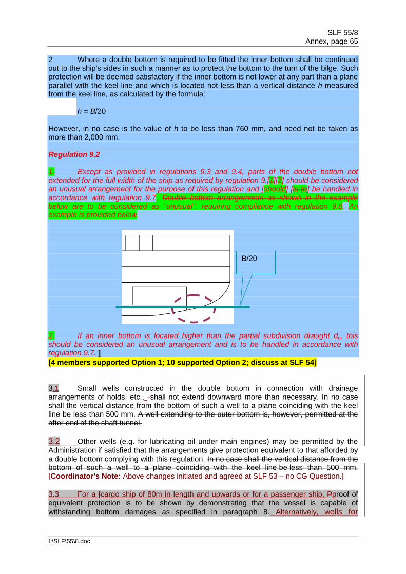
SLF 55/8 Annex, page 65
I:\SLF\55\8.doc
2 Where a double bottom is required to be fitted the inner bottom shall be continued out to the ship's sides in such a manner as to protect the bottom to the turn of the bilge. Such protection will be deemed satisfactory if the inner bottom is not lower at any part than a plane parallel with the keel line and which is located not less than a vertical distance h measured from the keel line, as calculated by the formula:
h = B/20
However, in no case is the value of h to be less than 760 mm, and need not be taken as more than 2,000 mm. Regulation 9.2 1. Except as provided in regulations 9.3 and 9.4, parts of the double bottom not extended for the full width of the ship as required by regulation 9.[1][2] should be considered an unusual arrangement for the purpose of this regulation and [should] [is to] be handled in accordance with regulation 9.7. Double bottom arrangements as shown in the example below are to be considered as "unusual", requiring compliance with regulation 9.8. An example is provided below. 2. If an inner bottom is located higher than the partial subdivision draught dp, this should be considered an unusual arrangement and is to be handled in accordance with regulation 9.7. ]
[4 members supported Option 1; 10 supported Option 2; discuss at SLF 54] 3.1 Small wells constructed in the double bottom in connection with drainage arrangements of holds, etc., shall not extend downward more than necessary. In no case shall the vertical distance from the bottom of such a well to a plane coinciding with the keel line be less than 500 mm. A well extending to the outer bottom is, however, permitted at the after end of the shaft tunnel.
3.2 Other wells (e.g. for lubricating oil under main engines) may be permitted by the
Administration if satisfied that the arrangements give protection equivalent to that afforded by a double bottom complying with this regulation. In no case shall the vertical distance from the bottom of such a well to a plane coinciding with the keel line be less than 500 mm. [Coordinator's Note: Above changes initiated and agreed at SLF 53 – no CG Question.]
3.3 For a [cargo ship of 80m in length and upwards or for a passenger ship, Pproof of equivalent protection is to be shown by demonstrating that the vessel is capable of
withstanding bottom damages as specified in paragraph 8. Alternatively, wells for
B/20

SLF 55/8 Annex, page 66
I:\SLF\55\8.doc
lubricating oil below main engines may protrude into the double bottom below the boundary line defined by the distance h provided that the distance between the well bottom and the bottom shell plating is not less than h/2. For cargo ships of less than
80m in length the alternative arrangements shall provide a level of safety satisfactory to the Administration. ] [Q65D] [New proposal from Germany; Voting 12-3 in favour; Japan has significant comments, however; discuss at SLF 54.]4 A double bottom need not be fitted in way of watertight tanks, including dry tanks of moderate size, provided the safety of the ship is not impaired in the event of bottom or side damage.
5 In the case of passenger ships to which the provisions of regulation 1.5 apply and which are engaged on regular service within the limits of a short international voyage as defined in regulation III/3.22, the Administration may permit a double bottom to be dispensed with if satisfied that the fitting of a double bottom in that part would not be compatible with the design and proper working of the ship. [Q6D(3)] [Asks members' opinion in general on the degree to which regulations 9.6 to 9.8 should be applied to small dry cargo ships – various options are given. Option(a) reduce s=1; 5 in favour; (b) introduce flexibility; 3 in favour (c) do not apply to small cargo vessels; 2 in favour of the United States and Japan comments; Option (d) other alternatives from RINA and Norway. Discuss at SLF 54.] 6 Any part of a cargo ship of 80 m in length and upwards or of a passenger ship or a cargo ship that is not fitted with a double bottom in accordance with paragraphs 1, 4 or 5 shall be capable of withstanding bottom damages, as specified in paragraph 8, in that part of the ship. For cargo ships of less than 80 m in length the alternative arrangements shall provide a level of safety satisfactory to the Administration. [This does not apply to small dry cargo ships.] [Q6D(4)[2]; discuss at SLF 54.] Regulation 9.6 1. Any part of a passenger ship or a cargo ship of 80 m in length and upwards where a double bottom is omitted in accordance with regulation 9.1, 9.4 or 9.5 shall be capable of withstanding bottom damages, as specified in regulation 9.8. The intent of this provision is to specify the circumstances under which the Administration should require calculations, which damage extents to assume and what survival criteria to apply when double bottoms are not fitted. [This does not apply to small dry cargo ships.] [Q6D(4)[2] discuss at SLF 54] 2. The definition of "watertight" in regulation 2.17 implies that the strength of inner bottoms and other boundaries assumed to be watertight should be verified if they are to be considered effective in this context. 7 In the case of unusual bottom arrangements in a cargo ship of 80 m in length and upwards or a passenger ship or a cargo ship, it shall be demonstrated that the ship is capable of withstanding bottom damages as specified in paragraph 8. [This does not apply to small dry cargo ships.] [Q6D(4)[4] discuss at SLF 54.]For cargo ships of less than 80 m in length the alternative arrangements shall provide a level of safety satisfactory to the Administration. Regulation 9.7

SLF 55/8 Annex, page 67
I:\SLF\55\8.doc
The reference to a "plane" in regulation 9.2 does not imply that the surface of the inner bottom may not be stepped in the vertical direction. Minor steps and recesses need not be considered unusual arrangements for the purpose of this paragraph as long as no part of the inner bottom is located below the reference plane. Discontinuities in way of wing tanks are covered by regulation 9.4.
8 Compliance with paragraphs 6 or 7 is to be achieved by demonstrating that si, when calculated in accordance with regulation 7-2, is not less than 1 for all service conditions when subject to a bottom damage assumed at any position along the ship's bottom and with an extent specified in subparagraph .2 below for the affected part of the ship:
.1 Flooding of such spaces shall not render emergency power and lighting,
internal communication, signals or other emergency devices inoperable in other parts of the ship.
.2 Assumed extent of damage shall be as follows:
For 0.3 L from the forward perpendicular of the ship
Any other part of the ship
Longitudinal Extent
1/3 L2/3 or 14.5 m, whichever is less
1/3 L2/3 or 14.5 m, whichever is less
Transverse Extent
B/6 or 10 m, whichever is less
B/6 or 5 m, whichever is less
Vertical Extent, measured from the keel line
B/20 or 2 m, whichever is less
B/20 or 2 m, whichever is less
[Q44D(1)] [Does this table need amending in the light of the GOALDS research or Japan's proposal? GOALDS may not look at L<80 m – may need to revise it ourselves; Discuss at SLF 54.]
.3 If any damage of a lesser extent than the maximum damage specified in
subparagraph .2 would result in a more severe condition, such damage should be considered.

SLF 55/8 Annex, page 68
I:\SLF\55\8.doc
Regulation 9.8 1. The term "all service conditions" used in this paragraph means the three loading conditions used to calculate the attained subdivision index A. 2. The damage extents specified in this paragraph should be applied to all parts of the ship where no double bottom is fitted, as permitted by regulations 9.1, 9.4 or 9.5, and include any adjacent spaces located within the extent of damage. [Q44D(3) 2 support Japan, 5 oppose. Discuss at SLF 54.] Small wells in accordance with regulation 9.3 do not need to be considered damaged even if within the extent of the damage. Possible positions of the damages are shown in an example below (parts of the ship not fitted with a double bottom are shaded; the damages to be assumed are indicated by boxes).
[Q44D(2)] [Clarification of green boxes, etc. needed. Will they show up in black and white? No problem here; Germany and Denmark explain that green colour is not significant. NFA]

SLF 55/8 Annex, page 69
I:\SLF\55\8.doc
9 In case of large lower holds in passenger ships, the Administration may require an increased double bottom height of not more than B/10 or 3 m, whichever is less, measured from the keel line. Alternatively, bottom damages may be calculated for these areas, in accordance with paragraph 8, but assuming an increased vertical extent. Regulation 9.9 1. For the purpose of identifying "large lower holds", horizontal surfaces having a continuous deck area greater than approximately 30% in comparison with the waterplane area at subdivision draught should be taken located anywhere in the affected area of the ship. For the alternative bottom damage calculation, a vertical extent of B/10 or 3 m, whichever is less, should be assumed. 2. The increased minimum double bottom height of not more than B/10 or 3 m, whichever is less, for passenger ships with large lower holds, is applicable to holds in direct contact with the double bottom. Typical arrangements of ro-ro passenger ships may include a large lower hold with additional tanks between the double bottom and the lower hold, as shown in the figure below. In such cases, the vertical position of the double bottom required to be B/10 or 3 m, whichever is less, should be applied to the lower hold deck, maintaining the required double bottom height of B/20 or 2 m, whichever is less (but not less than 760 mm). The figure below shows a typical arrangement of a modern ro-ro passenger ferry.
Regulation 10 Construction of watertight bulkheads [Q6D(4)[5]][Discuss at SLF 54] 1 Each watertight subdivision bulkhead, whether transverse or longitudinal, shall be constructed having scantlings as specified in regulation 2.17. In all cases, watertight subdivision bulkheads shall be capable of supporting at least the pressure due to a head of water up to the bulkhead deck [in passenger ships and freeboard deck in cargo ships]. [Q6D(4)[6]] [Discuss at SLF 54]

SLF 55/8 Annex, page 70
I:\SLF\55\8.doc
Regulation 10.1 For the treatment of steps in the bulkhead deck of passenger ships see Explanatory Notes for regulation 13. For the treatment of steps in the freeboard deck of cargo ships see Explanatory Notes for regulation 13-1. 2 Steps and recesses in watertight bulkheads shall be as strong as the bulkhead at the place where each occurs. Regulation 11 Initial testing of watertight bulkheads, etc. [Q6D(4)[7]] [Discuss at SLF 54] 1 Testing watertight spaces not intended to hold liquids and cargo holds intended to hold ballast by filling them with water is not compulsory. When testing by filling with water is not carried out, a hose test shall be carried out where practicable. This test shall be carried out in the most advanced stage of the fitting out of the ship. Where a hose test is not practicable because of possible damage to machinery, electrical equipment insulation or outfitting items, it may be replaced by a careful visual examination of welded connections, supported where deemed necessary by means such as a dye penetrant test or an ultrasonic leak test or an equivalent test. In any case a thorough inspection of the watertight bulkheads shall be carried out. 2 The forepeak, double bottom (including duct keels) and inner skins shall be tested with water to a head corresponding to the requirements of regulation 10.1. 3 Tanks which are intended to hold liquids, and which form part of the watertight subdivision of the ship, shall be tested for tightness and structural strength with water to a head corresponding to its design pressure. The water head is in no case to be less than the top of the air pipes or to a level of 2.4 m above the top of the tank, whichever is the greater. 4 The tests referred to in paragraphs 2 and 3 are for the purpose of ensuring that the subdivision structural arrangements are watertight and are not to be regarded as a test of the fitness of any compartment for the storage of oil fuel or for other special purposes for which a test of a superior character may be required depending on the height to which the liquid has access in the tank or its connections. Regulation 12 Peak and machinery space bulkheads, shaft tunnels, etc. [Q6D(4)[8]] [Discuss at SLF 54] 1 A collision bulkhead shall be fitted which shall be watertight up to the bulkhead deck [in passenger ships and freeboard deck in cargo ships] [Q6D(4)[9]] [Discuss at SLF 54]. This bulkhead shall be located at a distance from the forward perpendicular of not less than 0.05L or 10 m, whichever is the less, and, except as may be permitted by the Administration, not more than 0.08L or 0.05L + 3 m, whichever is the greater. [2 The ship shall be so designed that si calculated in accordance with regulation 7-2 will not be less than 1 [for all service conditions] [for the loading conditions on which is based the calculation of a subdivision index] if [the whole portion] [any part] of the ship forward of the collision bulkhead is [flooded] [damaged] without vertical limits.] [Q39-41D] [See also regulation 8.1. If accepted subsequent paragraph numbers will change. Square brackets to be decided.] [Discuss at SLF 54]

SLF 55/8 Annex, page 71
I:\SLF\55\8.doc
2 Where any part of the ship below the waterline extends forward of the forward perpendicular, e.g. a bulbous bow, the distances stipulated in paragraph 1 shall be measured from a point either:
.1 at the mid-length of such extension; .2 at a distance 0.015L forward of the forward perpendicular; or .3 at a distance 3 m forward of the forward perpendicular, whichever gives the smallest measurement.
3 The bulkhead may have steps or recesses provided they are within the limits prescribed in paragraph 1 or 2. 4 No doors, manholes, access openings, ventilation ducts or any other openings shall be fitted in the collision bulkhead below the bulkhead deck [in passenger ships and freeboard deck in cargo ships]. [Q6D(4)[10]] [Discuss at SLF 54] 5.1 Except as provided in paragraph 5.2, the collision bulkhead may be pierced below the bulkhead deck [in passenger ships and freeboard deck in cargo ships] [Q6D(4)[11]] [Discuss at SLF 54] by not more than one pipe for dealing with fluid in the forepeak tank, provided that the pipe is fitted with a [screw-down] [Q45D] [Most support is for a new EN with diagrams from document SLF 51/3/4; 9-1 in favour; discuss at SLF 54] valve capable of being operated from above the bulkhead deck [in passenger ships and freeboard deck in cargo ships] [Q6D(4)[12]] [ Discuss at SLF 54], [the valve chest being secured inside the forepeak to the collision bulkhead][ [Q45D(6)][1 in favour of retaining "valve chest", 3 against; Discuss at SLF 54]. The Administration may, however, authorize the fitting of this valve [on the after side of the collision bulkhead] [Q45D(8)] [Opinion evenly divided on France's proposal; discuss at SLF 54] provided that the valve is readily accessible under all service conditions and the space in which it is located is not a cargo space. All valves shall be of steel, bronze or other approved ductile material. Valves of ordinary cast iron or similar material are not acceptable. [Regulation 12.5.1 Possible new EN for "screw-down" valve.] [Q45D] [9-1 in favour; discuss at SLF 54] 5.2 If the forepeak is divided to hold two different kinds of liquids the Administration may allow the collision bulkhead to be pierced below the bulkhead deck [in passenger ships and freeboard deck in cargo ships] [Q6D(4)[13]] [Discuss at SLF 54] by two pipes, each of which is fitted as required by paragraph 5.1, provided the Administration is satisfied that there is no practical alternative to the fitting of such a second pipe and that, having regard to the additional subdivision provided in the forepeak, the safety of the ship is maintained. 6 Where a long forward superstructure is fitted the collision bulkhead shall be extended weathertight to the deck next above the bulkhead deck [in passenger ships and freeboard deck in cargo ships]. [Q6D(4)[14]] [Discuss at SLF 54] The extension need not be fitted directly above the bulkhead below provided it is located within the limits prescribed in paragraph 1 or 2 with the exception permitted by paragraph 7 and that the part of the deck which forms the step is made effectively weathertight. The extension shall be so arranged as to preclude the possibility of the bow door causing damage to it in the case of damage to, or detachment of, a bow door.

SLF 55/8 Annex, page 72
I:\SLF\55\8.doc
7 Where bow doors are fitted and a sloping loading ramp forms part of the extension of the collision bulkhead above the bulkhead deck the ramp shall be weathertight over its complete length. In cargo ships the part of the ramp which is more than 2.3 m above the [bulkhead] [freeboard] [Q6D(4)[15]] [Discuss at SLF 54] deck may extend forward of the limit specified in paragraph 1 or 2. Ramps not meeting the above requirements shall be disregarded as an extension of the collision bulkhead. Regulation 12.7 Reference is made to MSC.1/Circ.1211 (Unified interpretations to SOLAS regulation II-1/10 and regulation 12 of the revised SOLAS chapter II-1 regarding bow doors and the extension of the collision bulkhead) concerning interpretations regarding bow doors and the extension of the collision bulkhead. 8 The number of openings in the extension of the collision bulkhead above the freeboard deck shall be restricted to the minimum compatible with the design and normal operation of the ship. All such openings shall be capable of being closed weathertight. 9 Bulkheads shall be fitted separating the machinery space from cargo and accommodation spaces forward and aft and made watertight up to the bulkhead deck [in passenger ships and freeboard deck in cargo ships] [Q6D(4) [16]] [Discuss at SLF 54]. In passenger ships an afterpeak bulkhead shall also be fitted and made watertight up to the bulkhead deck. The afterpeak bulkhead may, however, be stepped below the bulkhead deck, provided the degree of safety of the ship as regards subdivision is not thereby diminished. 10 In all cases stern tubes shall be enclosed in watertight spaces of moderate volume. In passenger ships the stern gland shall be situated in a watertight shaft tunnel or other watertight space separate from the stern tube compartment and of such volume that, if flooded by leakage through the stern gland, the bulkhead deck will not be immersed. In cargo ships other measures to minimize the danger of water penetrating into the ship in case of damage to stern tube arrangements may be taken at the discretion of the Administration. Regulation 12.10 − Stern Tubes Reference is made to MSC/Circ.[xxxx] (Unified interpretation of SOLAS chapter II-1) regarding enclosure of stern tubes on cargo ships. [Possible new EN for IACS UI; Discuss at SLF 54] Regulation 13 Openings in watertight bulkheads below the bulkhead deck in passenger ships General – Steps in the bulkhead deck 1. If the transverse watertight bulkheads in a region of the ship are carried to a higher deck which forms a vertical step in the bulkhead deck, openings located in the bulkhead at the step may be considered as being located above the bulkhead deck. Such openings should then comply with regulation 17 and should be taken into account when applying regulation 7-2. 2. All openings in the shell plating below the upper deck throughout that region of the ship should be treated as being below the bulkhead deck and the provisions of regulation 15 should be applied. See figure below.

SLF 55/8 Annex, page 73
I:\SLF\55\8.doc
1 Bulkhead deck 2 Considered as located above the bulkhead deck 3 Ship's side 4 Considered as located below the bulkhead deck
1 The number of openings in watertight bulkheads shall be reduced to the minimum compatible with the design and proper working of the ship, satisfactory means shall be provided for closing these openings.
2.1 Where pipes, scuppers, electric cables, etc., are carried through watertight bulkheads, arrangements shall be made to ensure the watertight integrity of the bulkheads. 2.2 Valves not forming part of a piping system shall not be permitted in watertight bulkheads. 2.3 Lead or other heat sensitive materials shall not be used in systems which penetrate watertight bulkheads, where deterioration of such systems in the event of fire would impair the watertight integrity of the bulkheads. 3 No doors, manholes, or access openings are permitted in watertight transverse bulkheads dividing a cargo space from an adjoining cargo space, except as provided in paragraph 9.1 and in regulation 14. 4 Subject to paragraph 10, not more than one door, apart from the doors to shaft tunnels, may be fitted in each watertight bulkhead within spaces containing the main and auxiliary propulsion machinery including boilers serving the needs of propulsion. Where two or more shafts are fitted, the tunnels shall be connected by an intercommunicating passage. There shall be only one door between the machinery space and the tunnel spaces where two shafts are fitted and only two doors where there are more than two shafts. All these doors shall be of the sliding type and shall be so located as to have their sills as high as practicable. The hand gear for operating these doors from above the bulkhead deck shall be situated outside the spaces containing the machinery. Regulation 13.4 In cases where main and auxiliary propulsion machinery spaces, including boilers serving the needs for propulsion, are divided by watertight longitudinal bulkheads in order to comply with redundancy requirements (e.g. according to regulation 8-1.2), one watertight door in each watertight bulkhead may be permitted, as shown in the figure below.

SLF 55/8 Annex, page 74
I:\SLF\55\8.doc
5.1 Watertight doors, except as provided in paragraph 9.1 or regulation 14, shall be power-operated sliding doors complying with the requirements of paragraph 7 capable of being closed simultaneously from the central operating console at the navigation bridge in not more than 60 s with the ship in the upright position. 5.2 The means of operation whether by power or by hand of any power-operated sliding watertight door shall be capable of closing the door with the ship listed to 15°
either way. Consideration shall also be given to the forces which may act on either side of the door as may be experienced when water is flowing through the opening applying a static head equivalent to a water height of at least 1 m above the sill on the centreline of the door. 5.3 Watertight door controls, including hydraulic piping and electric cables, shall be kept as close as practicable to the bulkhead in which the doors are fitted, in order to minimize the likelihood of them being involved in any damage which the ship may sustain. The positioning of watertight doors and their controls shall be such that if the ship sustains damage within one fifth of the breadth of the ship, as defined in regulation 2, such distance being measured at right angles to the centreline at the level of the deepest subdivision draught, the operation of the watertight doors clear of the damaged portion of the ship is not impaired. [CLIA Q15C] [Ask the SLF Sub-Committee to raise issue of routeing of cables, etc., and B/5 with the DE Sub-Committee.] 6 All power-operated sliding watertight doors shall be provided with means of indication which will show at all remote operating positions whether the doors are open or closed. Remote operating positions shall only be at the navigation bridge as required by paragraph 7.1.5 and at the location where hand operation above the bulkhead deck is required by paragraph 7.1.4. 7.1 Each power-operated sliding watertight door:
.1 shall have a vertical or horizontal motion; .2 shall, subject to paragraph 10, be normally limited to a maximum clear
opening width of 1.2 m. The Administration may permit larger doors only to the extent considered necessary for the effective operation of the ship provided that other safety measures, including the following, are taken into consideration:
SLF 55/8 Annex, page 75
I:\SLF\55\8.doc
.1 special consideration shall be given to the strength of the door and its closing appliances in order to prevent leakages; and
.2 the door shall be located inboard the damage zone B/5;
.3 shall be fitted with the necessary equipment to open and close the door
using electric power, hydraulic power, or any other form of power that is acceptable to the Administration;
.4 shall be provided with an individual hand-operated mechanism. It shall be
possible to open and close the door by hand at the door itself from either side, and in addition, close the door from an accessible position above the bulkhead deck with an all round crank motion or some other movement providing the same degree of safety acceptable to the Administration. Direction of rotation or other movement is to be clearly indicated at all operating positions. The time necessary for the complete closure of the door, when operating by hand gear, shall not exceed 90 s with the ship in the upright position;
.5 shall be provided with controls for opening and closing the door by power
from both sides of the door and also for closing the door by power from the central operating console at the navigation bridge;
.6 shall be provided with an audible alarm, distinct from any other alarm in the
area, which will sound whenever the door is closed remotely by power and which shall sound for at least 5 s but no more than 10 s before the door begins to move and shall continue sounding until the door is completely closed. In the case of remote hand operation it is sufficient for the audible alarm to sound only when the door is moving. Additionally, in passenger areas and areas of high ambient noise the Administration may require the audible alarm to be supplemented by an intermittent visual signal at the door; and
.7 shall have an approximately uniform rate of closure under power.
The closure time, from the time the door begins to move to the time it reaches the completely closed position shall, in no case be less than 20 s or more than 40 s with the ship in the upright position.
7.2 The electrical power required for power-operated sliding watertight doors shall be supplied from the emergency switchboard either directly or by a dedicated distribution board situated above the bulkhead deck. The associated control, indication and alarm circuits shall be supplied from the emergency switchboard either directly or by a dedicated distribution board situated above the bulkhead deck and be capable of being automatically supplied by the transitional source of emergency electrical power required by regulation 42.3.1.3 in the event of failure of either the main or emergency source of electrical power. 7.3 Power-operated sliding watertight doors shall have either:
.1 a centralized hydraulic system with two independent power sources each consisting of a motor and pump capable of simultaneously closing all doors. In addition, there shall be for the whole installation hydraulic accumulators of sufficient capacity to operate all the doors at least three times, i.e. closed-open-closed, against an adverse list of 15°. This operating cycle shall be capable of being carried out when the accumulator is at the pump

SLF 55/8 Annex, page 76
I:\SLF\55\8.doc
cut-in pressure. The fluid used shall be chosen considering the temperatures liable to be encountered by the installation during its service. The power operating system shall be designed to minimize the possibility of having a single failure in the hydraulic piping adversely affect the operation of more than one door. The hydraulic system shall be provided with a low-level alarm for hydraulic fluid reservoirs serving the power-operated system and a low gas pressure alarm or other effective means of monitoring loss of stored energy in hydraulic accumulators. These alarms are to be audible and visual and shall be situated on the central operating console at the navigation bridge; or
.2 an independent hydraulic system for each door with each power source
consisting of a motor and pump capable of opening and closing the door. In addition, there shall be a hydraulic accumulator of sufficient capacity to operate the door at least three times, i.e. closed-open-closed, against an adverse list of 15°. This operating cycle shall be capable of being carried out when the accumulator is at the pump cut-in pressure. The fluid used shall be chosen considering the temperatures liable to be encountered by the installation during its service. A low gas pressure group alarm or other effective means of monitoring loss of stored energy in hydraulic accumulators shall be provided at the central operating console on the navigation bridge. Loss of stored energy indication at each local operating position shall also be provided; or
.3 an independent electrical system and motor for each door with each power
source consisting of a motor capable of opening and closing the door. The power source shall be capable of being automatically supplied by the transitional source of emergency electrical power as required by regulation 42.4.2 – in the event of failure of either the main or emergency source of electrical power and with sufficient capacity to operate the door at least three times, i.e. closed-open-closed, against an adverse list of 15°.
For the systems specified in paragraphs 7.3.1, 7.3.2 and 7.3.3, provision should be made as follows: Power systems for power-operated watertight sliding doors shall be separate from any other power system. A single failure in the electric or hydraulic power-operated systems excluding the hydraulic actuator shall not prevent the hand operation of any door. 7.4 Control handles shall be provided at each side of the bulkhead at a minimum height of 1.6 m above the floor and shall be so arranged as to enable persons passing through the doorway to hold both handles in the open position without being able to set the power closing mechanism in operation accidentally. The direction of movement of the handles in opening and closing the door shall be in the direction of door movement and shall be clearly indicated. 7.5 As far as practicable, electrical equipment and components for watertight doors shall be situated above the bulkhead deck and outside hazardous areas and spaces. 7.6 The enclosures of electrical components necessarily situated below the bulkhead deck shall provide suitable protection against the ingress of water.* [Regulation 13.7.6
The IEC standard referenced in the footnote (IEC publication 529, 1976) has been replaced
by the newer standard IEC 60529:2003.] [Coordinator's Comment: This EN could be
deleted as the SOLAS 2009 Consolidated Edition now has the correct reference?]

SLF 55/8 Annex, page 77
I:\SLF\55\8.doc
7.7 Electric power, control, indication and alarm circuits shall be protected against fault in such a way that a failure in one door circuit will not cause a failure in any other door circuit. Short circuits or other faults in the alarm or indicator circuits of a door shall not result in a loss of power operation of that door. Arrangements shall be such that leakage of water into the electrical equipment located below the bulkhead deck will not cause the door to open.
_____________ Refer to the following publication IEC 60529:2003):
.1 electrical motors, associated circuits and control components; protected to IPX 7 standard;
.2 door position indicators and associated circuit components; protected to IPX 8 standard; and
.3 door movement warning signals; protected to IPX 6 standard.
Other arrangements for the enclosures of electrical components may be fitted provided the Administration is satisfied that an equivalent protection is achieved. The water pressure IPX 8 shall be based on the pressure that may occur at the location of the component during flooding for a period of 36 h.
7.8 A single electrical failure in the power operating or control system of a power-operated sliding watertight door shall not result in a closed door opening. Availability of the power supply should be continuously monitored at a point in the electrical circuit as near as practicable to each of the motors required by paragraph 7.3. Loss of any such power supply should activate an audible and visual alarm at the central operating console at the navigation bridge. 8.1 The central operating console at the navigation bridge shall have a "master mode" switch with two modes of control: a "local control" mode which shall allow any door to be locally opened and locally closed after use without automatic closure, and a "doors closed" mode which shall automatically close any door that is open. The "doors closed" mode shall automatically close any door that is open. The "doors closed" mode shall permit doors to be opened locally and shall automatically re-close the doors upon release of the local control mechanism. The "master mode" switch shall normally be in the "local control" mode. The "doors closed" mode shall only be used in an emergency or for testing purposes. Special consideration shall be given to the reliability of the "master mode" switch. 8.2 The central operating console at the navigation bridge shall be provided with a diagram showing the location of each door, with visual indicators to show whether each door is open or closed. A red light shall indicate a door is fully open and a green light shall indicate a door is fully closed. When the door is closed remotely the red light shall indicate the intermediate position by flashing. The indicating circuit shall be independent of the control circuit for each door. 8.3 It shall not be possible to remotely open any door from the central operating console. 9.1 If the Administration is satisfied that such doors are essential, watertight doors of satisfactory construction may be fitted in watertight bulkheads dividing cargo between deck spaces. Such doors may be hinged, rolling or sliding doors but shall not be remotely controlled. They shall be fitted at the highest level and as far from the shell plating as practicable, but in no case shall the outboard vertical edges be situated at a distance from the shell plating which is less than one fifth of the breadth of the ship, as defined in regulation 2, such distance being measured at right angles to the centreline at the level of the deepest subdivision draught.

SLF 55/8 Annex, page 78
I:\SLF\55\8.doc
9.2 Should any such doors be accessible during the voyage, they shall be fitted with a device which prevents unauthorized opening. When it is proposed to fit such doors, the number and arrangements shall receive the special consideration of the Administration. 10 Portable plates on bulkheads shall not be permitted except in machinery spaces. The Administration may permit not more than one power-operated sliding watertight door in each watertight bulkhead larger than those specified in paragraph 7.1.2 to be substituted for these portable plates, provided these doors are intended to remain closed during navigation except in case of urgent necessity at the discretion of the master. These doors need not meet the requirements of paragraph 7.1.4 regarding complete closure by hand-operated gear in 90 s. 11.1 Where trunkways or tunnels for access from crew accommodation to the stokehold machinery spaces [Q46], for piping, or for any other purpose are carried through watertight bulkheads, they shall be watertight and in accordance with the requirements of regulation 16-1. The access to at least one end of each such tunnel or trunkway, if used as a passage at sea, shall be through a trunk extending watertight to a height sufficient to permit access above the bulkhead deck. The access to the other end of the trunkway or tunnel may be through a watertight door of the type required by its location in the ship. Such trunkways or tunnels shall not extend through the first subdivision bulkhead abaft the collision bulkhead. 11.2 Where it is proposed to fit tunnels piercing watertight bulkheads, these shall receive the special consideration of the Administration. 11.3 Where trunkways in connection with refrigerated cargo and ventilation or forced draught trunks are carried through more than one watertight bulkhead, the means of closure at such openings shall be operated by power and be capable of being closed from a central position situated above the bulkhead deck. Regulation 13-1 Openings in watertight bulkheads and internal decks in cargo ships [This regulation does not apply to small dry cargo ships.] [Q6D(4)[17]]
[Coordinator's Note: This has been added because the regulation is taken verbatim from old SOLAS regulation II-1/25-9, applicable only to cargo vessels with L >= 80 m but see also new question Q68D. Perhaps some (or all) of these paragraphs should apply to small dry cargo ships? Comments are invited in [Q6D(4)[17]][Discuss at SLF 54]] 1 The number of openings in watertight subdivisions is to be kept to a minimum compatible with the design and proper working of the ship. Where penetrations of watertight bulkheads and internal decks are necessary for access, piping, ventilation, electrical cables, etc., arrangements are to be made to maintain the watertight integrity. The Administration may permit relaxation in the watertightness of openings above the freeboard deck, provided that it is demonstrated that any progressive flooding can be easily controlled and that the safety of the ship is not impaired. Regulation 13-1.1 1. If the transverse watertight bulkheads in a region of the ship are carried to a higher deck than in the remainder of the ship, openings located in the bulkhead at the step may be considered as being located above the freeboard deck.

SLF 55/8 Annex, page 79
I:\SLF\55\8.doc
2. All openings in the shell plating below the upper deck throughout that region of the ship should be treated as being below the freeboard deck, similar to the bulkhead deck for passenger ships (see relevant figure under regulation 13 above), and the provisions of regulation 15 should be applied. 2 Doors provided to ensure the watertight integrity of internal openings which are used while at sea are to be [sliding watertight doors] [Q68D][10-1 believe that all watertight doors for all cargo ships are to be sliding; 6-3 believe this was not planned; 4-4 in question of sliding doors for L<80 m; Norway, IACS, RINA have comments; discuss at SLF 54] capable of being remotely closed from the bridge and are also to be operable locally from each side of the bulkhead. Indicators are to be provided at the control position showing whether the doors are open or closed, and an audible alarm is to be provided at the door closure. The power, control and indicators are to be operable in the event of main power failure. Particular attention is to be paid to minimizing the effect of control system failure. Each power-operated sliding watertight door shall be provided with an individual hand-operated mechanism. It shall be possible to open and close the door by hand at the door itself from both sides. 3 Access doors and access hatch covers normally closed at sea, intended to ensure the watertight integrity of internal openings, shall be provided with means of indication locally and on the bridge showing whether these doors or hatch covers are open or closed. A notice is to be affixed to each such door or hatch cover to the effect that it is not to be left open. 4 Watertight doors or ramps [Coordinator's Note: Ramps may be weathertight in regulation 17-1.1.2 – conflict referred to ro-ro correspondence group] of satisfactory construction may be fitted to internally subdivide large cargo spaces, provided that the Administration is satisfied that such doors or ramps are essential. These doors or ramps may be hinged, rolling or sliding doors or ramps, but shall not be remotely controlled.* Should any of the doors or ramps be accessible during the voyage, they shall be fitted with a device which prevents unauthorized opening. 5 Other closing appliances which are kept permanently closed at sea to ensure the watertight integrity of internal openings shall be provided with a notice which is to be affixed to each such closing appliance to the effect that it is to be kept closed. Manholes fitted with closely bolted covers need not be so marked.
Regulation 14 Passenger ships carrying goods vehicles and accompanying personnel 1 This regulation applies to passenger ships designed or adapted for the carriage of goods vehicles and accompanying personnel. 2 If in such a ship the total number of passengers which include personnel accompanying vehicles does not exceed 12 + Ad/25, where Ad = total deck area (square metres) of spaces available for the stowage of goods vehicles and where the clear height at the stowage position and at the entrance to such spaces is not less than 4 m, the provisions of regulations 13.9.1 and 13.9.2 in respect of watertight doors apply except that the doors may be fitted at any level in watertight bulkheads dividing cargo spaces. Additionally, indicators are required on the navigation bridge to show automatically when each door is closed and all door fastenings are secured. 3 The ship may not be certified for a higher number of passengers than assumed in paragraph 2, if a watertight door has been fitted in accordance with this regulation.

SLF 55/8 Annex, page 80
I:\SLF\55\8.doc
Regulation 15 Openings in the shell plating below the bulkhead deck of passenger ships and the freeboard deck of cargo ships
[Coordinator's Note: We have assumed that the bulkhead deck/freeboard deck terminology is correct throughout this regulation which we think should apply to all cargo ships?][Q6D(4)][Discuss at SLF 54] General – Steps in the bulkhead deck and freeboard deck For the treatment of steps in the bulkhead deck of passenger ships see Explanatory Notes for regulation 13. For the treatment of steps in the freeboard deck of cargo ships see Explanatory Notes for regulation 13-1.
____________ Refer to Interpretations of regulations of part B-1 of SOLAS chapter II-1 (MSC/Circ.651).
1 The number of openings in the shell plating shall be reduced to the minimum compatible with the design and proper working of the ship. 2 The arrangement and efficiency of the means for closing any opening in the shell plating shall be consistent with its intended purpose and the position in which it is fitted and generally to the satisfaction of the Administration. 3.1 Subject to the requirements of the International Convention on Load Lines in force, no sidescuttle shall be fitted in such a position that its sill is below a line drawn parallel to the bulkhead deck at side and having its lowest point 2.5% of the breadth of the ship above the deepest subdivision draught, or 500 mm, whichever is the greater. 3.2 All sidescuttles the sills of which are below the bulkhead deck of passenger ships and the freeboard deck of cargo ships, as permitted by paragraph 3.1, shall be of such construction as will effectively prevent any person opening them without the consent of the master of the ship. 4 Efficient hinged inside deadlights so arranged that they can be easily and effectively closed and secured watertight, shall be fitted to all sidescuttles except that abaft one eighth of the ship's length from the forward perpendicular and above a line drawn parallel to the bulkhead deck at side and having its lowest point at a height of 3.7 m plus 2.5% of the breadth of the ship above the deepest subdivision draught, the deadlights may be portable in passenger accommodation other than that for steerage passengers [Q47], unless the deadlights are required by the International Convention on Load Lines in force to be permanently attached in their proper positions. Such portable deadlights shall be stowed adjacent to the sidescuttles they serve. 5.1 No sidescuttles shall be fitted in any spaces which are appropriated exclusively to the carriage of cargo or coal. [Q48] 5.2 Sidescuttles may, however, be fitted in spaces appropriated alternatively to the carriage of cargo or passengers, but they shall be of such construction as will effectively prevent any person opening them or their deadlights without the consent of the master. 6 Automatic ventilating sidescuttles shall not be fitted in the shell plating below the bulkhead deck of passenger ships and the freeboard deck of cargo ships without the special sanction of the Administration.

SLF 55/8 Annex, page 81
I:\SLF\55\8.doc
7 The number of scuppers, sanitary discharges and other similar openings in the shell plating shall be reduced to the minimum either by making each discharge serve for as many as possible of the sanitary and other pipes, or in any other satisfactory manner. 8.1 All inlets and discharges in the shell plating shall be fitted with efficient and accessible arrangements for preventing the accidental admission of water into the ship. 8.2.1 Subject to the requirements of the International Convention on Load Lines in force, and except as provided in paragraph 8.3, each separate discharge led through the shell plating from spaces below the bulkhead deck of passenger ships and the freeboard deck of cargo ships shall be provided with either one automatic non-return valve fitted with a positive means of closing it from above the bulkhead deck or with two automatic non-return valves without positive means of closing, provided that the inboard valve is situated above the deepest subdivision draught and is always accessible for examination under service conditions. Where a valve with positive means of closing is fitted, the operating position above the bulkhead deck shall always be readily accessible and means shall be provided for indicating whether the valve is open or closed. 8.2.2 The requirements of the International Convention on Load Lines in force shall apply to discharges led through the shell plating from spaces above the bulkhead deck of passenger ships and the freeboard deck of cargo ships. 8.3 Machinery space, main and auxiliary sea inlets and discharges in connection with the operation of machinery shall be fitted with readily accessible valves between the pipes and the shell plating or between the pipes and fabricated boxes attached to the shell plating. In manned machinery spaces the valves may be controlled locally and shall be provided with indicators showing whether they are open or closed. 8.4 Moving parts penetrating the shell plating below the deepest subdivision draught shall be fitted with a watertight sealing arrangement acceptable to the Administration. The inboard gland shall be located within a watertight space of such volume that, if flooded, the bulkhead deck will not be submerged. The Administration may require that if such compartment is flooded, essential or emergency power and lighting, internal communication, signals or other emergency devices must remain available in other parts of the ship. 8.5 All shell fittings and valves required by this regulation shall be of steel, bronze or other approved ductile material. Valves of ordinary cast iron or similar material are not acceptable. All pipes to which this regulation refers shall be of steel or other equivalent material to the satisfaction of the Administration. 9 Gangway, cargo and fuelling ports fitted below the bulkhead deck of passenger ships and the freeboard deck of cargo ships shall be watertight and in no case be so fitted as to have their lowest point below the deepest subdivision draught. 10.1 The inboard opening of each ash-chute, rubbish-chute, etc., shall be fitted with an efficient cover. 10.2 If the inboard opening is situated below the bulkhead deck of passenger ships and the freeboard deck of cargo ships, the cover shall be watertight and, in addition, an automatic non-return valve shall be fitted in the chute in an easily accessible position above the deepest subdivision draught.

SLF 55/8 Annex, page 82
I:\SLF\55\8.doc
Regulation 15-1 External openings in cargo ships [This regulation does not apply to small dry cargo ships?] [Q6D(4)[18]] [Coordinator's Note: The item in square brackets has been added because the regulation is based on old SOLAS regulation II-1/25-10, applicable only to cargo vessels with L >= 80 m; [Discuss at SLF 54]] 1 All external openings leading to compartments assumed intact in the damage analysis, which are below the final damage waterline, are required to be watertight. Regulation 15-1.1 With regard to air-pipe closing devices, they should be considered weathertight closing devices (not watertight). This is consistent with their treatment in regulation 7-2.5.2.1. However, in the context of regulation 15-1, "external openings" are not intended to include air-pipe openings. 2 External openings required to be watertight in accordance with paragraph 1 shall, except for cargo hatch covers, be fitted with indicators on the bridge.
3 Openings in the shell plating below the deck limiting the vertical extent of damage shall be fitted with a device that prevents unauthorized opening if they are accessible during the voyage. 4 Other closing appliances which are kept permanently closed at sea to ensure the watertight integrity of external openings shall be provided with a notice affixed to each appliance to the effect that it is to be kept closed. Manholes fitted with closely bolted covers need not be so marked.

SLF 55/8 Annex, page 83
I:\SLF\55\8.doc
Regulation 16 Construction and initial tests of watertight doors, sidescuttles, etc. [Default – provided changes are made as shown below] [Q6D(4)[19]] [Discuss at SLF 54] 1 In all ships:
.1 the design, materials and construction of all watertight doors, sidescuttles,
gangway and cargo ports, valves, pipes, ash-chutes and rubbish-chutes referred to in these regulations shall be to the satisfaction of the Administration;
.2 such valves, doors and mechanisms shall be suitably marked to ensure
that they may be properly used to provide maximum safety; and .3 the frames of vertical watertight doors shall have no groove at the bottom in
which dirt might lodge and prevent the door closing properly. 2 In passenger ships and cargo ships watertight doors shall be tested by water pressure to a head of water [measured from the lower edge of the door opening to the bulkhead deck or the freeboard deck][they might sustain in a final or intermediate stage of flooding] [Q6D(4)[20]]. [Coordinator's Note: as it stands this is a "deterministic" criterion – would it not be better to simply use a head of water to the bulkhead deck in passenger ships or the freeboard deck in cargo ships? For small dry cargo ships this also avoids the problem of having to undertake a full damage stability analysis simply to determine the test head for a watertight door– see Q6D Round 6 Discussion paragraphs 5.4 and 5.5 for more details]. [Discuss at SLF 54] Where testing of individual doors is not carried out because of possible damage to insulation or outfitting items, testing of individual doors may be replaced by a prototype pressure test of each type and size of door with a test pressure corresponding at least to the head required for the intended location. The prototype test shall be carried out before the door is fitted. The installation method and procedure for fitting the door on board shall correspond to that of the prototype test. When fitted on board, each door shall be checked for proper seating between the bulkhead, the frame and the door. Regulation 16.2 1. Watertight doors should be tested by water pressure to a head of water measured from the lower edge of the door opening to the bulkhead deck or the freeboard deck[, or to the most unfavourable final or intermediate waterplane during flooding, whichever is greater.] [See coordinator's note above for reason for proposed deletion. If the above text change to the regulation is approved, EN 1 could be deleted entirely.] [Discuss at SLF 54] 2. Large doors, hatches or ramps on passenger and cargo ships, of a design and size that would make pressure testing impracticable, may be exempted from regulation 16.2, provided it is demonstrated by calculations that the doors, hatches or ramps maintain watertightness at design pressure with a proper margin of resistance. Where such doors utilize gasket seals, a prototype pressure test to confirm that the compression of the gasket material is capable of accommodating any deflection, revealed by the structural analysis, should be carried out. After installation every such door, hatch or ramp should be tested by means of a hose test or equivalent. Note: See Explanatory Notes for regulation 13 for additional information regarding the
treatment of steps in the bulkhead deck of passenger ships. See Explanatory Notes for regulation 13-1 for additional information regarding the treatment of steps in the freeboard deck of cargo ships.

SLF 55/8 Annex, page 84
I:\SLF\55\8.doc
Regulation 16-1 Construction and initial tests of watertight decks, trunks, etc. [Default] [Q6D(4)[21]] [Discuss at SLF 54] 1 Watertight decks, trunks, tunnels, duct keels and ventilators shall be of the same strength as watertight bulkheads at corresponding levels. The means used for making them watertight, and the arrangements adopted for closing openings in them, shall be to the satisfaction of the Administration. Watertight ventilators and trunks shall be carried at least up to the bulkhead deck in passenger ships and up to the freeboard deck in cargo ships. 2 [For passenger ships,] [W][w]here [Q6D(4)[22]] [Discuss at SLF 54]a ventilation trunk passing through a structure penetrates the bulkhead deck, the trunk shall be capable of withstanding the water pressure that may be present within the trunk, after having taken into account the maximum heel angle allowable during intermediate stages of flooding, in accordance with regulation 7-2. [Coordinator's Note: This paragraph originally came from SOLAS 2002, regulation II-1/19.2, where it applied only to ro-pax ships. It cannot refer to a cargo ship as it mentions IS flooding. Therefore we propose to add the qualifier at the beginning, as shown.] 3 Where all or part of the penetration of the bulkhead deck is on the main ro-ro deck, the trunk shall be capable of withstanding impact pressure due to internal water motions (sloshing) of water trapped on the ro-ro deck. 4 After completion, a hose or flooding test shall be applied to watertight decks and a hose test to watertight trunks, tunnels and ventilators. Regulation 17 Internal watertight integrity of passenger ships above the bulkhead deck General – Steps in the bulkhead deck For the treatment of steps in the bulkhead deck of passenger ships see Explanatory Notes for regulation 13. 1 The Administration may require that all reasonable and practicable measures shall be taken to limit the entry and spread of water above the bulkhead deck. Such measures may include partial bulkheads or webs. When partial watertight bulkheads and webs are fitted on the bulkhead deck, above or in the immediate vicinity of watertight bulkheads, they shall have watertight shell and bulkhead deck connections so as to restrict the flow of water along the deck when the ship is in a heeled damaged condition. Where the partial watertight bulkhead does not line up with the bulkhead below, the bulkhead deck between shall be made effectively watertight. Where openings, pipes, scuppers, electric cables etc. are carried through the partial watertight bulkheads or decks within the immersed part of the bulkhead deck, arrangements shall be made to ensure the watertight integrity of the structure above the bulkhead deck.[*] [Regulation 17.1 Watertight sliding doors with reduced pressure head complying with the requirements of MSC/Circ.541, as may be amended, should be in line with regulation 7-2.5.2.1. These types of tested watertight sliding doors with reduced pressure head could be immersed during intermediate stages of flooding.] [CLIAQ16D] [Coordinator's Note: 3 options were given; responses from Round 6 were 5-3 in favour of France; 1-6 support the United States; 7-4 support coordinators; Norway has an alternative;

SLF 55/8 Annex, page 85
I:\SLF\55\8.doc
Finland provides detailed info on semi-watertight doors; Germany says we need to take FLOODSTAND findings into account.] [Discuss at SLF 54] 2 All openings in the exposed weather deck shall have coamings of ample height and strength and shall be provided with efficient means for expeditiously closing them weathertight. Freeing ports, open rails and scuppers shall be fitted as necessary for rapidly clearing the weather deck of water under all weather conditions. 3 [The open end of air pipes terminating within a superstructure shall be at least 1 m above the waterline when the ship heels to an angle of 15º, or the maximum angle of heel during intermediate stages of flooding, as determined by direct calculation, whichever is the greater. Alternatively, air pipes from tanks other than oil tanks may discharge through the side of the superstructure. The provisions of this paragraph are without prejudice to the provisions of the International Convention on Load Lines in force. ] [Air pipes terminating within a superstructure which are not fitted with watertight means of closure shall be considered as unprotected openings when applying regulation 7-2.6.1.1.] [Q49D] Regulation 17.3 [These provisions regarding the open end of air pipes should be applied only to damages of longitudinal and transverse extent as defined in regulation 8.3 but limited to the bulkhead deck and involving tanks having their open end terminating within the superstructure.] [This paragraph is intended to ensure that flooding of volumes located above a horizontal division in the superstructure will be taken into consideration if a side or bottom damage would cause flooding via tanks or spaces located below the waterline.] [Q50D] [These changes (regulation 17.3 and EN) were unanimously agreed to by the correspondence group] [recommend acceptance]
___________ Refer to the Guidance notes on the integrity of flooding boundaries above the bulkhead deck of
passenger ships for proper application of regulations II-1/8 and 20, paragraph 1, of SOLAS 1974, as amended (MSC/Circ.541, as may be amended). [CLIA Q16D]
4 Sidescuttles, gangway, cargo and fuelling ports and other means for closing openings in the shell plating above the bulkhead deck shall be of efficient design and construction and of sufficient strength having regard to the spaces in which they are fitted and their positions relative to the deepest subdivision draught**.
5 Efficient inside deadlights, so arranged that they can be easily and effectively closed and secured watertight, shall be provided for all sidescuttles to spaces below the first deck above the bulkhead deck. Regulation 17-1 Integrity of the hull and superstructure, damage prevention and control on ro-ro passenger ships 1.1 Subject to the provisions of paragraphs 1.2 and 1.3, all accesses that lead to spaces below the bulkhead deck shall have a lowest point which is not less than 2.5 m above the bulkhead deck.

SLF 55/8 Annex, page 86
I:\SLF\55\8.doc
Regulation 17-1.1.1 − Accesses leading to spaces below the bulkhead deck Reference is made to MSC/Circ.[xxxx] (Unified interpretation of SOLAS chapter II-1) regarding special requirements for vehicle ferries, ro-ro ships and other ships of similar type. [Possible new EN for IACS UI; Discuss at SLF 54.] 1.2 Where vehicle ramps are installed to give access to spaces below the bulkhead deck, their openings shall be able to be closed [weathertight] [Q51] [Coordinator's Note: Ramps must be watertight in regulation 13-1.4 – conflict referred to ro-ro correspondence group] to prevent ingress of water below, alarmed and indicated to the navigation bridge. 1.3 The Administration may permit the fitting of particular accesses to spaces below the bulkhead deck provided they are necessary for the essential working of the ship, e.g. the movement of machinery and stores, subject to such accesses being made watertight, alarmed and indicated on the navigation bridge. 2 Indicators shall be provided on the navigation bridge for all shell doors, loading doors and other closing appliances which, if left open or not properly secured, could, in the opinion of the Administration, lead to flooding of a special category space or ro-ro space. The indicator system shall be designed on the fail-safe principle and shall show by visual alarms if the door is not fully closed or if any of the securing arrangements are not in place and fully locked and by audible alarms if such door or closing appliances become open or the securing arrangements become unsecured. The indicator panel on the navigation bridge shall be equipped with a mode selection function "harbour/sea voyage" so arranged that an audible alarm is given on the navigation bridge if the ship leaves harbour with the bow doors, inner doors, stern ramp or any other side shell doors not closed or any closing device not in the correct position. The power supply for the indicator system shall be independent of the power supply for operating and securing the doors. 3 Television surveillance and a water leakage detection system shall be arranged to provide an indication to the navigation bridge and to the engine control station of any leakage through inner and outer bow doors, stern doors or any other shell doors which could lead to flooding of special category spaces or ro-ro spaces.
____________ ** Refer to the Recommendation on strength and security and locking arrangements of shell doors
on ro-ro passenger ships, adopted by the Organization by resolution A.793(19).
Part B-3
Subdivision load line assignment for passenger ships Regulation 18 Assigning, marking and recording of subdivision load lines for passenger ships 1 In order that the required degree of subdivision shall be maintained, a load line corresponding to the approved subdivision draught shall be assigned and marked on the ship's sides. A ship intended for alternating modes of operation may, if the owners desire, have one or more additional load lines assigned and marked to correspond with the subdivision draughts which the Administration may approve for the alternative service configurations. Each service configuration so approved shall comply with part B-1 of this chapter independently of the results obtained for other modes of operation. 2 The subdivision load lines assigned and marked shall be recorded in the Passenger Ship Safety Certificate, and shall be distinguished by the notation P1 for the principal

SLF 55/8 Annex, page 87
I:\SLF\55\8.doc
passenger service configuration, and P2, P3, etc., for the alternative configurations. The principal passenger configuration shall be taken as the mode of operation in which the required subdivision index R will have the highest value. 3 The freeboard corresponding to each of these load lines shall be measured at the same position and from the same deck line as the freeboards determined in accordance with the International Convention on Load Lines in force. 4 The freeboard corresponding to each approved subdivision load line and the service configuration, for which it is approved, shall be clearly indicated on the Passenger Ship Safety Certificate. 5 In no case shall any subdivision load line mark be placed above the deepest load line in salt water as determined by the strength of the ship or the International Convention on Load Lines in force. 6 Whatever may be the position of the subdivision load line marks, a ship shall in no case be loaded so as to submerge the load line mark appropriate to the season and locality as determined in accordance with the International Convention on Load Lines in force. 7 A ship shall in no case be so loaded that when it is in salt water the subdivision load line mark appropriate to the particular voyage and service configuration is submerged.
Part B-4 Stability management
Regulation 19 Damage control information [Default] [Q6D(4)[23]][Discuss at SLF 54] 1 There shall be permanently exhibited, or readily available on the navigation bridge, for the guidance of the officer in charge of the ship, plans showing clearly for each deck and hold the boundaries of the watertight compartments, the openings therein with the means of closure and position of any controls thereof, and the arrangements for the correction of any list due to flooding. In addition, booklets containing the aforementioned information shall be made available to the officers of the ship*. 2 Watertight doors in passenger ships permitted to remain open during navigation shall be clearly indicated in the ship's stability information. 3 General precautions to be included shall consist of a listing of equipment, conditions, and operational procedures, considered by the Administration to be necessary to maintain watertight integrity under normal ship operations. 4 Specific precautions to be included shall consist of a listing of elements (i.e. closures, security of cargo, sounding of alarms, etc.) considered by the Administration to be vital to the survival of the ship, passengers and crew. 5 In case of ships to which damage stability requirements of part B-1 apply, damage stability information shall provide the master a simple and easily understandable way of assessing the ship's survivability in all damage cases [Q52D][6-3 were in favour of Germany amending the Appendix to the EN; 4-4 on Japan's proposal for consequence diagrams][Discuss at SLF 54] involving a compartment or group of compartments.
SLF 55/8 Annex, page 88
I:\SLF\55\8.doc
Regulation 20 Loading of [passenger] ships [Q53D][ 10-3 in favour of deleting "passenger"] [Discuss at SLF 54] 1 On completion of loading of the ship and prior to its departure, the master shall determine the ship's trim and stability and also ascertain and record that the ship is [upright and] [within [x] degrees of upright and] [Q54D][13-0 in favour of discussion at SLF 54] in compliance with stability criteria in relevant regulations. The determination of the ship's stability shall always be made by calculation. The Administration may accept the use of an electronic loading and stability computer or equivalent means for this purpose. [Regulation 20.1 "Upright" means with a maximum list of + / - [0.5] [1] [2] degrees to ensure the validity of compliance with the intact and damage stability regulations.] [Q55D][See Q54D] 2 Water ballast should not in general be carried in tanks intended for oil fuel. In ships in which it is not practicable to avoid putting water in oil fuel tanks, oily-water separating equipment to the satisfaction of the Administration shall be fitted, or other alternative means, such as discharge to shore facilities, acceptable to the Administration shall be provided for disposing of the oily-water ballast. 3 The provisions of this regulation are without prejudice to the provisions of the International Convention for the Prevention of Pollution from Ships in force.
______________ Refer to the Guidelines for damage control plans and information to the master
(MSC.1/Circ.1245).
Regulation 21 Periodical operation and inspection of watertight doors, etc., in passenger ships 1 Drills for the operating of watertight doors, sidescuttles, valves and closing mechanisms of scuppers, ash-chutes and rubbish-chutes shall take place weekly. In ships in which the voyage exceeds one week in duration a complete drill shall be held before leaving port, and others thereafter at least once a week during the voyage. 2 All watertight doors, both hinged and power operated, in watertight bulkheads, in use at sea, shall be operated daily. 3 The watertight doors and all mechanisms and indicators connected therewith, all valves, the closing of which is necessary to make a compartment watertight, and all valves the operation of which is necessary for damage control cross connections shall be periodically inspected at sea at least once a week. 4 A record of all drills and inspections required by this regulation shall be entered in the logbook with an explicit record of any defects which may be disclosed. Regulation 22 Prevention and control of water ingress, etc. Default] [Q6D(4)[24]][Discuss at SLF 54] 1 All watertight doors shall be kept closed during navigation except that they may be opened during navigation as specified in paragraphs 3 and 4. Watertight doors of a width of more than 1.2 m in machinery spaces as permitted by regulation 13.10 may only be opened

SLF 55/8 Annex, page 89
I:\SLF\55\8.doc
in the circumstances detailed in that regulation. Any door which is opened in accordance with this paragraph shall be ready to be immediately closed. 2 Watertight doors located below the bulkhead deck [in passenger ships and freeboard deck in cargo ships] [Q6D(4) [25]] [Discuss at SLF 54] having a maximum clear opening width of more than 1.2 m shall be kept closed when the ship is at sea, except for limited periods when absolutely necessary as determined by the Administration. 3 A watertight door may be opened during navigation to permit the passage of passengers or crew, or when work in the immediate vicinity of the door necessitates it being opened. The door must be immediately closed when transit through the door is complete or when the task which necessitated it being open is finished. 4 Certain watertight doors may be permitted to remain open during navigation only if considered absolutely necessary; that is, being open is determined essential to the safe and effective operation of the ship's machinery or to permit passengers normally unrestricted access throughout the passenger area. Such determination shall be made by the Administration only after careful consideration of the impact on ship operations and survivability. A watertight door permitted to remain thus open shall be clearly indicated in the ship's stability information and shall always be ready to be immediately closed[*]. [Q57D]
____________
[ Refer to the Guidance for watertight doors on passenger ships which may be opened during
navigation (MSC.1/Circ.1380)] [Q57D][Advise Secretariat to add footnote]
5 Portable plates on bulkheads shall always be in place before the ship leaves port, and shall not be removed during navigation except in case of urgent necessity at the discretion of the master. The necessary precautions shall be taken in replacing them to ensure that the joints are watertight. Power-operated sliding watertight doors permitted in machinery spaces in accordance with regulation 13.10 shall be closed before the ship leaves port and shall remain closed during navigation except in case of urgent necessity at the discretion of the master. 6 Watertight doors fitted in watertight bulkheads dividing cargo between deck spaces in accordance with regulation 13.9.1 shall be closed before the voyage commences and shall be kept closed during navigation; the time of opening such doors in port and of closing them before the ship leaves port shall be entered in the logbook. 7 Gangway, cargo and fuelling ports fitted below the bulkhead deck [in passenger ships and freeboard deck in cargo ships] [Q6D(4) [26]] [Discuss at SLF 54] shall be effectively closed and secured watertight before the ship leaves port, and shall be kept closed during navigation. 8 The following doors, located above the bulkhead deck [in passenger ships and freeboard deck in cargo ships] [Q6D(4) [27]] [Discuss at SLF 54], shall be closed and locked before the ship proceeds on any voyage and shall remain closed and locked until the ship is at its next berth:
.1 cargo loading doors in the shell or the boundaries of enclosed
superstructures; .2 bow visors fitted in positions as indicated in paragraph 8.1; .3 cargo loading doors in the collision bulkhead; and

SLF 55/8 Annex, page 90
I:\SLF\55\8.doc
.4 ramps forming an alternative closure to those defined in paragraphs 8.1 to 8.3 inclusive.
9 Provided that where a door cannot be opened or closed while the ship is at the berth such a door may be opened or left open while the ship approaches or draws away from the berth, but only so far as may be necessary to enable the door to be immediately operated. In any case, the inner bow door must be kept closed. 10 Notwithstanding the requirements of paragraphs 8.1 and 8.4, the Administration may authorize that particular doors can be opened at the discretion of the master, if necessary for the operation of the ship or the embarking and disembarking of passengers when the ship is at safe anchorage and provided that the safety of the ship is not impaired. 11 The master shall ensure that an effective system of supervision and reporting of the closing and opening of the doors referred to in paragraph 8 is implemented. 12 The master shall ensure, before the ship proceeds on any voyage, that an entry in the logbook is made of the time of the last closing of the doors specified in paragraph 13 and the time of any opening of particular doors in accordance with paragraph 14. 13 Hinged doors, portable plates, sidescuttles, gangway, cargo and bunkering ports and other openings, which are required by these regulations to be kept closed during navigation, shall be closed before the ship leaves port. The time of closing and the time of opening (if permissible under these regulations) shall be recorded in such logbook as may be prescribed by the Administration. 14 Where in a between-decks, the sills of any of the sidescuttles referred to in regulation 15.3.2 are below a line drawn parallel to the bulkhead deck at side [in passenger ships and freeboard deck at side in cargo ships] [Q6D(4) [28]] [Discuss at SLF 54] and having its lowest point 1.4 m plus 2.5% of the breadth of the ship above the water when the ship departs from any port, all the sidescuttles in that between-decks shall be closed watertight and locked before the ship leaves port, and they shall not be opened before the ship arrives at the next port. In the application of this paragraph the appropriate allowance for fresh water may be made when applicable.
.1 The time of opening such sidescuttles in port and of closing and locking
them before the ship leaves port shall be entered in such logbook as may be prescribed by the Administration.
.2 For any ship that has one or more sidescuttles so placed that the
requirements of paragraph 14 would apply when it was floating at its deepest subdivision draught, the Administration may indicate the limiting mean draught at which these sidescuttles will have their sills above the line drawn parallel to the bulkhead deck at side [in passenger ships and freeboard deck at side in cargo ships] [Q6D(4) [29]] [Discuss at SLF 54], and having its lowest point 1.4 m plus 2.5% of the breadth of the ship above the waterline corresponding to the limiting mean draught, and at which it will therefore be permissible to depart from port without previously closing and locking them and to open them at sea on the responsibility of the master during the voyage to the next port. In tropical zones as defined in the International Convention on Load Lines in force, this limiting draught may be increased by 0.3 m.

SLF 55/8 Annex, page 91
I:\SLF\55\8.doc
15 Sidescuttles and their deadlights which will not be accessible during navigation shall be closed and secured before the ship leaves port. 16 If cargo is carried in spaces referred to in regulation 15.5.2, the sidescuttles and their deadlights shall be closed watertight and locked before the cargo is shipped and such closing and locking shall be recorded in such logbook as may be prescribed by the Administration. 17 When a rubbish-chute, etc. is not in use, both the cover and the valve required by regulation 15.10.2 shall be kept closed and secured. Regulation 22-1*
Flooding detection systems for passenger ships carrying 36 or more persons constructed on or after 1 July 2010 A flooding detection system for watertight spaces below the bulkhead deck shall be provided based on the guidelines developed by the Organization.*
___________ Refer to the guidelines for flooding detection systems on passenger ships (MSC.1/Circ.1291).
Regulation 23 Special requirements for ro-ro passenger ships 1 Special category spaces and ro-ro spaces shall be continuously patrolled or monitored by effective means, such as television surveillance, so that any movement of vehicles in adverse weather conditions and unauthorized access by passengers thereto can be detected whilst the ship is underway. 2 Documented operating procedures for closing and securing all shell doors, loading doors and other closing appliances which, if left open or not properly secured, could, in the opinion of the Administration, lead to flooding of a special category space or ro-ro space, shall be kept on board and posted at an appropriate place. 3 All accesses from the ro-ro deck and vehicle ramps that lead to spaces below the bulkhead deck shall be closed before the ship leaves the berth on any voyage and shall remain closed until the ship is at its next berth. 4 The master shall ensure that an effective system of supervision and reporting of the closing and opening of such accesses referred to in paragraph 3 is implemented. 5 The master shall ensure, before the ship leaves the berth on any voyage, that an entry in the logbook, as required by regulation 22.13, is made of the time of the last closing of the accesses referred to in paragraph 3. 6 Notwithstanding the requirements of paragraph 3, the Administration may permit some accesses to be opened during the voyage, but only for a period sufficient to permit through passage and, if required, for the essential working of the ship. 7 All transverse or longitudinal bulkheads which are taken into account as effective to confine the seawater accumulated on the ro-ro deck shall be in place and secured before the ship leaves the berth and remain in place and secured until the ship is at its next berth.
SLF 55/8 Annex, page 92
I:\SLF\55\8.doc
8 Notwithstanding the requirements of paragraph 7, the Administration may permit some accesses within such bulkheads to be opened during the voyage but only for sufficient time to permit through passage and, if required, for the essential working of the ship. 9 In all ro-ro passenger ships, the master or the designated officer shall ensure that, without the expressed consent of the master or the designated officer, no passengers are allowed access to an enclosed ro-ro deck when the ship is under way. Regulation 24 [Additional requirements for p][P]revention and control of water ingress, etc., in cargo ships [Q58D] [13-0 in favour; recommend change]
1 Openings in the shell plating below the deck limiting the vertical extent of damage shall be kept permanently closed while at sea. 2 Notwithstanding the requirements of paragraph 3, the Administration may authorize that particular doors may be opened at the discretion of the master, if necessary for the operation of the ship and provided that the safety of the ship is not impaired. 3 Watertight doors or ramps fitted internally to subdivide large cargo spaces shall be closed before the voyage commences and shall be kept closed during navigation; the time of opening such doors in port and of closing them before the ship leaves port shall be entered in the logbook. 4 The use of access doors and hatch covers intended to ensure the watertight integrity of internal openings shall be authorized by the officer of the watch.
Regulation 25 Water level detectors on single hold cargo ships other than bulk carriers 1 Single hold cargo ships other than bulk carriers constructed before 1 January 2007 shall comply with the requirements of this regulation not later than 31 December 2009. 2 Ships having a length (L) of less than 80 m, or 100 m if constructed before 1 July 1998, and a single cargo hold below the freeboard deck or cargo holds below the freeboard deck which are not separated by at least one bulkhead made watertight up to that deck, shall be fitted in such space or spaces with water level detectors*.
3 The water level detectors required by paragraph 2 shall:
.1 give an audible and visual alarm at the navigation bridge when the water
level above the inner bottom in the cargo hold reaches a height of not less than 0.3 m, and another when such level reaches not more than 15% of the mean depth of the cargo hold; and
.2 be fitted at the aft end of the hold, or above its lowest part where the inner
bottom is not parallel to the designed waterline. Where webs or partial watertight bulkheads are fitted above the inner bottom, Administrations may require the fitting of additional detectors.

SLF 55/8 Annex, page 93
I:\SLF\55\8.doc
4 The water level detectors required by paragraph 2 need not be fitted in ships complying with regulation XII/12, or in ships having watertight side compartments each side of the cargo hold length extending vertically at least from inner bottom to freeboard deck.
___________ Refer to the Performance standards for water level detectors on bulk carriers and single hold
cargo ships other than bulk carriers, adopted by the Maritime Safety Committee by resolution MSC.188(79).
Part C
(Regulation 35-1 only)
Machinery Installations (Except where expressly stated otherwise part C
applies to passenger ships and cargo ships) Regulation 35-1 Bilge pumping arrangements [CLIA Q17D][12-0 in favour of discussing B/5 and checking A.265 at SLF 54;] 1 This regulation applies to ships constructed on or after 1 January 2009. 2 Passenger ships and cargo ships 2.1 An efficient bilge pumping system shall be provided, capable of pumping from and draining any watertight compartment other than a space permanently appropriated for the carriage of fresh water, water ballast, oil fuel or liquid cargo and for which other efficient means of pumping are provided, under all practical conditions. Efficient means shall be provided for draining water from insulated holds. 2.2 Sanitary, ballast and general service pumps may be accepted as independent power bilge pumps if fitted with the necessary connections to the bilge pumping system. 2.3 All bilge pipes used in or under coal bunkers or [Q59B]fuel storage tanks or in boiler or machinery spaces, including spaces in which oil-settling tanks or oil fuel pumping units are situated, shall be of steel or other suitable material. 2.4 The arrangement of the bilge and ballast pumping system shall be such as to prevent the possibility of water passing from the sea and from water ballast spaces into the cargo and machinery spaces, or from one compartment to another. Provision shall be made to prevent any deep tank having bilge and ballast connections being inadvertently flooded from the sea when containing cargo, or being discharged through a bilge pump when containing water ballast. 2.5 All distribution boxes and manually operated valves in connection with the bilge pumping arrangements shall be in positions which are accessible under ordinary circumstances. 2.6 Provision shall be made for the drainage of enclosed cargo spaces situated on the bulkhead deck of a passenger ship and on the freeboard deck of a cargo ship, provided that the Administration may permit the means of drainage to be dispensed with in any particular compartment of any ship or class of ship if it is satisfied that by reason of size or internal subdivision of those spaces the safety of the ship is not thereby impaired. [For the special hazards associated with loss of stability in ships fitted with fixed pressure water-spraying fire-extinguishing systems see II-2/20.6.1.4.*].

SLF 55/8 Annex, page 94
I:\SLF\55\8.doc
*Refer to MSC.1/Circ.1320 on [...] [Q60C][No objections – recommend extra sentence and to ask the Secretariat to add a footnote in reference to MSC.1/Circ.1320 to II-2/20.6.1.4] 2.6.1 Where the freeboard to the bulkhead deck or the freeboard deck, respectively, is such that the deck edge is immersed when the ship heels more than 5°, the drainage shall be by means of a sufficient number of scuppers of suitable size discharging directly overboard, fitted in accordance with the requirements of regulation 15 in the case of a passenger ship and the requirements for scuppers, inlets and discharges of the International Convention on Load Lines in force in the case of a cargo ship. Regulation 35-1.2.6.1 − Drainage of bulkhead deck or freeboard deck Reference is made to MSC/Circ.[xxxx] (Unified interpretation of SOLAS chapter II-1) regarding special requirements for vehicle ferries, ro-ro ships and other ships of similar type. [Possible new EN for IACS UI; Discuss at SLF 54] 2.6.2 Where the freeboard is such that the edge of the bulkhead deck or the edge of the freeboard deck, respectively, is immersed when the ship heels 5° or less, the drainage of the enclosed cargo spaces on the bulkhead deck or on the freeboard deck, respectively, shall be led to a suitable space, or spaces, of adequate capacity, having a high water level alarm and provided with suitable arrangements for discharge overboard. In addition it shall be ensured that:
.1 the number, size and disposition of the scuppers are such as to prevent
unreasonable accumulation of free water; .2 the pumping arrangements required by this regulation for passenger ships
or cargo ships, as applicable, take account of the requirements for any fixed pressure water-spraying fire-extinguishing system;
.3 water contaminated with petrol or other dangerous substances is not
drained to machinery spaces or other spaces where sources of ignition may be present; and
.4 where the enclosed cargo space is protected by a carbon dioxide
fire-extinguishing system the deck scuppers are fitted with means to prevent the escape of the smothering gas.
3 Passenger ships 3.1 The bilge pumping system required by paragraph 2.1 shall be capable of operation under all practicable conditions after a casualty whether the ship is upright or listed. For this purpose wing suctions shall generally be fitted except in narrow compartments at the end of the ship where one suction may be sufficient. In compartments of unusual form, additional suctions may be required. Arrangements shall be made whereby water in the compartment may find its way to the suction pipes. Where, for particular compartments, the Administration is satisfied that the provision of drainage may be undesirable, it may allow such provision to be dispensed with if calculations made in accordance with the conditions laid down in regulations 7 and 8 show that the survival capability of the ship will not be impaired. 3.2 At least three power pumps shall be fitted connected to the bilge main, one of which may be driven by the propulsion machinery. Where the bilge pump numeral is 30 or more, one additional independent power pump shall be provided.

SLF 55/8 Annex, page 95
I:\SLF\55\8.doc
The bilge pump numeral shall be calculated as follows:
where:
L = the length of the ship (metres), as defined in regulation 2;
M = the volume of the machinery space (cubic metres), as defined in
regulation 2, that is below the bulkhead deck; with the addition thereto of the volume of any permanent oil fuel bunkers which may be situated above the inner bottom and forward of, or abaft, the machinery space;
P = the whole volume of the passenger and crew spaces below the bulkhead
deck (cubic metres), which are provided for the accommodation and use of passengers and crew, excluding baggage, store, provision and mail rooms;
V = the whole volume of the ship below the bulkhead deck (cubic metres); P1 = KN,
where: N = the number of passengers for which the ship is to be certified; and K = 0.056L [Q61] [No change to L? Majority are in favour. To be
confirmed at SLF 54. Norway, China and Vanuatu oppose] However, where the value of KN is greater than the sum of P and the whole volume of the actual passenger spaces above the bulkhead deck, the figure to be taken as P1 is that sum or two-thirds KN, whichever is the greater.
3.3 Where practicable, the power bilge pumps shall be placed in separate watertight compartments and so arranged or situated that these compartments will not be flooded by the same damage. If the main propulsion machinery, auxiliary machinery and boilers are in two or more watertight compartments, the pumps available for bilge service shall be distributed as far as is possible throughout these compartments. 3.4 On a ship of 91.5 m in length [L] [Q62] [Insertion to be confirmed at SLF 54. Norway and China oppose] and upwards or having a bilge pump numeral, calculated in accordance with paragraph 3.2, of 30 or more, the arrangements shall be such that at least one power bilge pump shall be available for use in all flooding conditions which the ship is required to withstand, as follows:

SLF 55/8 Annex, page 96
I:\SLF\55\8.doc
Regulation 35-1.3.4 For ships required to fulfil the damage stability requirements of part B-1 the words "in all flooding conditions which the ship is required to withstand" should be taken to mean all damages of minor extent according to regulation 8 and all damages contributing to the attained index, A. [Q62D][11-2 in favour of France's proposal; CLIA EC oppose. Discuss at SLF 54]
.1 one of the required bilge pumps shall be an emergency pump of a reliable
submersible type having a source of power situated above the bulkhead deck; or
.2 the bilge pumps and their sources of power shall be so distributed throughout the length of the ship that at least one pump in an undamaged compartment will be available.
3.5 With the exception of additional pumps which may be provided for peak compartments only, each required bilge pump shall be so arranged as to draw water from any space required to be drained by paragraph 2.1. 3.6 Each power bilge pump shall be capable of pumping water through the required main bilge pipe at a speed of not less than 2 m/s. Independent power bilge pumps situated in machinery spaces shall have direct suctions from these spaces, except that not more than two such suctions shall be required in any one space. Where two or more such suctions are provided, there shall be at least one on each side of the ship. The Administration may require independent power bilge pumps situated in other spaces to have separate direct suctions. Direct suctions shall be suitably arranged and those in a machinery space shall be of a diameter not less than that required for the bilge main. 3.7.1 In addition to the direct bilge suction or suctions required by paragraph 3.6, a direct suction from the main circulating pump leading to the drainage level of the machinery space and fitted with a non-return valve shall be provided in the machinery space. The diameter of this direct suction pipe shall be at least two thirds of the diameter of the pump inlet in the case of steamships, and of the same diameter as the pump inlet in the case of motorships. 3.7.2 Where in the opinion of the Administration the main circulating pump is not suitable for this purpose, a direct emergency bilge suction shall be led from the largest available independent power driven pump to the drainage level of the machinery space; the suction shall be of the same diameter as the main inlet of the pump used. The capacity of the pump so connected shall exceed that of a required bilge pump by an amount deemed satisfactory by the Administration. 3.7.3 The spindles of the sea inlet and direct suction valves shall extend well above the engine-room platform. 3.8 All bilge suction piping up to the connection to the pumps shall be independent of other piping.
SLF 55/8 Annex, page 97
I:\SLF\55\8.doc
3.9 The diameter d of the bilge main shall be calculated according to the following formula. However, the actual internal diameter of the bilge main may be rounded off to the nearest standard size acceptable to the Administration:
where:
d is the internal diameter of the bilge main (millimetres); L and B are the length and the breadth of the ship (metres) as defined in regulation 2; and [Q63] [No change to L? To be confirmed at SLF 54. Norway opposed] D is the moulded depth of the ship to the bulkhead deck (metres) provided that, in a ship having an enclosed cargo space on the bulkhead deck which is internally drained in accordance with the requirements of paragraph 2.6.2 and which extends for the full length of the ship, D shall be measured to the next deck above the bulkhead deck. Where the enclosed cargo spaces cover a lesser length, D shall be taken as the moulded depth to the bulkhead deck plus lh/L where l and h are the aggregate length and height respectively of the enclosed cargo spaces (metres). The diameter of the bilge branch pipes shall meet the requirements of the Administration.
3.10 Provision shall be made to prevent the compartment served by any bilge suction pipe being flooded in the event of the pipe being severed or otherwise damaged by collision or grounding in any other compartment. For this purpose, where the pipe is at any part situated nearer the side of the ship than one fifth of the breadth of the ship [CLIA Q17D – discuss B/5 at SLF 54; check A.265] (as defined in regulation 2 and measured at right angles to the centreline at the level of the deepest subdivision [load line] [draught]) [Q64][No objections – recommend accept], or is in a duct keel [Q64] [No change to "duct keel"? To be confirmed at SLF 54], a non-return valve shall be fitted to the pipe in the compartment containing the open end. 3.11 Distribution boxes, cocks and valves in connection with the bilge pumping system shall be so arranged that, in the event of flooding, one of the bilge pumps may be operative on any compartment; in addition, damage to a pump or its pipe connecting to the bilge main outboard of a line drawn at one fifth of the breadth of the ship shall not put the bilge system out of action. If there is only one system of pipes common to all the pumps, the necessary valves for controlling the bilge suctions must be capable of being operated from above the bulkhead deck. Where in addition to the main bilge pumping system an emergency bilge pumping system is provided, it shall be independent of the main system and so arranged that a pump is capable of operating on any compartment under flooding condition as specified in paragraph 3.1; in that case only the valves necessary for the operation of the emergency system need be capable of being operated from above the bulkhead deck. 3.12 All cocks and valves referred to in paragraph 3.11 which can be operated from above the bulkhead deck shall have their controls at their place of operation clearly marked and shall be provided with means to indicate whether they are open or closed. 4 Cargo ships At least two power pumps connected to the main bilge system shall be provided, one of which may be driven by the propulsion machinery. If the Administration is satisfied that the safety of the ship is not impaired, bilge pumping arrangements may be dispensed with in particular compartments.

SLF 55/8 Annex, page 98
I:\SLF\55\8.doc
APPENDIX
GUIDELINES FOR THE PREPARATION OF SUBDIVISION AND DAMAGE STABILITY CALCULATIONS
1 GENERAL
1.1 Purpose of the Guidelines
1.1.1 These Guidelines serve the purpose of simplifying the process of the damage stability analysis, as experience has shown that a systematic and complete presentation of the particulars results in considerable saving of time during the approval process.
1.1.2 A damage stability analysis serves the purpose to provide proof of the damage stability standard required for the respective ship type. At present, two different calculation methods, the deterministic concept and the probabilistic concept are applied.
1.2 Scope of analysis and documentation on board
1.2.1 The scope of subdivision and damage stability analysis is determined by the required damage stability standard and aims at providing the ship's master with clear intact stability requirements. In general, this is achieved by determining KG-respective GM-limit curves, containing the admissible stability values for the draught range to be covered.
1.2.2 Within the scope of the analysis thus defined, all potential or necessary damage conditions will be determined, taking into account the damage stability criteria, in order to obtain the required damage stability standard. Depending on the type and size of ship, this may involve a considerable amount of analyses.
1.2.3 Referring to SOLAS chapter II-1, regulation 19, the necessity to provide the crew with the relevant information regarding the subdivision of the ship is expressed, therefore plans should be provided and permanently exhibited for the guidance of the officer in charge. These plans should clearly show for each deck and hold the boundaries of the watertight compartments, the openings therein with means of closure and position of any controls thereof, and the arrangements for the correction of any list due to flooding. In addition, Damage Control Booklets containing the aforementioned information should be available.
2 DOCUMENTS FOR SUBMISSION
2.1 Presentation of documents
The documentation should begin with the following details: principal dimensions, ship type, designation of intact conditions, designation of damage conditions and pertinent damaged compartments, KG-respective GM-limit curve.
2.2 General documents
For checking of the input data, the following should be submitted:
.1 main dimensions;
.2 lines plan, plotted or numerical;
.3 hydrostatic data and cross curves of stability (including drawing of the buoyant hull);

SLF 55/8 Annex, page 99
I:\SLF\55\8.doc
.4 definition of sub-compartments with moulded volumes, centres of gravity and permeability;
.5 layout plan (watertight integrity plan) for the sub-compartments with all internal and external opening points including their connected sub-compartments, and particulars used in measuring the spaces, such as general arrangement plan and tank plan. The subdivision limits, longitudinal, transverse and vertical, should be included;
.6 light service condition;
.7 load line draught; .8 coordinates of opening points with their level of tightness (e.g. weathertight,
unprotected); .9 watertight door location with pressure calculation;
.10 side contour and wind profile;
.11 cross and down flooding devices and the calculations thereof according to resolution MSC.245(83) with information about diameter, valves, pipes length and coordinates of inlet/outlet;
.12 pipes in damaged area when the destruction of these pipes results in progressive flooding; and
.13 damage extensions and definition of damage cases.
2.3 Special documents The following documentation of results should be submitted. 2.3.1 Documentation 2.3.1.1 Initial data:
.1 subdivision length Ls;
.2 initial draughts and the corresponding GM-values;
.3 required subdivision index R; and
.4 attained subdivision index A with a summary table for all contributions for all damaged zones.
2.3.1.2 Results for each damage case which contributes to the index A:
.1 draught, trim, heel, GM in damaged condition;
.2 dimension of the damage with probabilistic values p, v and r;
.3 righting lever curves (including GZmax and range) with factor of survivability s;

SLF 55/8 Annex, page 100
I:\SLF\55\8.doc
.4 critical weathertight and unprotected openings with their angle of immersion; and
.5 details of sub-compartments with amount of in-flooded water/lost buoyancy with their centres of gravity.
2.3.1.3 In addition to the above requirements in 2.3.1.2, particulars of non-contributing damages (si = 0 and pi > 0.00) should also be submitted for passenger ships and ro-ro ships fitted with long lower holds including full details of the calculated factors. 2.3.2 Special consideration For intermediate conditions as stages before cross-flooding or before progressive flooding, an appropriate scope of the documentation covering the aforementioned items is needed in addition.
___________


![Recent Advances in Damage Stability Assessment with ... · E SOLAS damaged stability rules post-2009 Probabilistic ‘Regulation A’ is described in MSN 1698M (MCA, 1998) [9]. A](https://img.dokumen.tips/doc/110x75/5e7160a7113e3a6b9a622b2d/recent-advances-in-damage-stability-assessment-with-e-solas-damaged-stability.jpg)