Embed Size (px)
Citation preview

Andrew Corporation10500 West 153rd StreetOrland Park, IL U.S.A. 60462
Telephone: 708-349-3300FAX (U.S.A.): 1-800-349-5444Internet: http://www.andrew.com
Customer Service, 24 hours: U.S.A. • Canada • Mexico: 1-800-255-1479U.K.: 0800 250055 • Republic of Ireland: 1 800 535358Other Europe: +44 1592 782612 Printed in U.S.A. 9/00
Copyright © 2000 by Andrew Corporation
Installation, Operation and Maintenance Bulletin OM37
Type ES37( )
3.7-Meter ESA
3.7-Meter Earth Station Antenna
Revision C

Introduction
How to Use This Manual
Getting Started
InstallationProcedures
Operation
PreventiveMaintenance
Table of Contents2
Table of ContentsIntroduction . . . . . . . . . . . . . . . . . . . . . . . . . . . . . . . . . . . . . . . . . . . . . . . . . . . . . . . . . . . . . . . . . . . . . . . . . . 3
Proprietary Data . . . . . . . . . . . . . . . . . . . . . . . . . . . . . . . . . . . . . . . . . . . . . . . . . . . . . . . . . . . . . . . . . . 4Information and Assistance . . . . . . . . . . . . . . . . . . . . . . . . . . . . . . . . . . . . . . . . . . . . . . . . . . . . . . . . . 4Notice . . . . . . . . . . . . . . . . . . . . . . . . . . . . . . . . . . . . . . . . . . . . . . . . . . . . . . . . . . . . . . . . . . . . . . . . . . 4Technical Assistance . . . . . . . . . . . . . . . . . . . . . . . . . . . . . . . . . . . . . . . . . . . . . . . . . . . . . . . . . . . . . . 4
Overview . . . . . . . . . . . . . . . . . . . . . . . . . . . . . . . . . . . . . . . . . . . . . . . . . . . . . . . . . . . . . . . . . . . . . . . . . . . . 5Content . . . . . . . . . . . . . . . . . . . . . . . . . . . . . . . . . . . . . . . . . . . . . . . . . . . . . . . . . . . . . . . . . . . . . . . . . 5
Overview . . . . . . . . . . . . . . . . . . . . . . . . . . . . . . . . . . . . . . . . . . . . . . . . . . . . . . . . . . . . . . . . . . . . . . . . . . . . 6Warnings . . . . . . . . . . . . . . . . . . . . . . . . . . . . . . . . . . . . . . . . . . . . . . . . . . . . . . . . . . . . . . . . . . . . . . . . 6Recommended Tools . . . . . . . . . . . . . . . . . . . . . . . . . . . . . . . . . . . . . . . . . . . . . . . . . . . . . . . . . . . . . . 7Parts Verification . . . . . . . . . . . . . . . . . . . . . . . . . . . . . . . . . . . . . . . . . . . . . . . . . . . . . . . . . . . . . . . . . . 8Reporting Equipment Loss or Damage . . . . . . . . . . . . . . . . . . . . . . . . . . . . . . . . . . . . . . . . . . . . . . . . 8Reporting Visible Loss or Damage. . . . . . . . . . . . . . . . . . . . . . . . . . . . . . . . . . . . . . . . . . . . . . . . . . . . 8Reporting Concealed Damage. . . . . . . . . . . . . . . . . . . . . . . . . . . . . . . . . . . . . . . . . . . . . . . . . . . . . . . . 8Inventory Equipment Received . . . . . . . . . . . . . . . . . . . . . . . . . . . . . . . . . . . . . . . . . . . . . . . . . . . . . . 8Returning Equipment . . . . . . . . . . . . . . . . . . . . . . . . . . . . . . . . . . . . . . . . . . . . . . . . . . . . . . . . . . . . . . 9Installation Sequence Checklist . . . . . . . . . . . . . . . . . . . . . . . . . . . . . . . . . . . . . . . . . . . . . . . . . . . . . . 10Site Preparation. . . . . . . . . . . . . . . . . . . . . . . . . . . . . . . . . . . . . . . . . . . . . . . . . . . . . . . . . . . . . . . . . . . 10Ground Mount Assembly. . . . . . . . . . . . . . . . . . . . . . . . . . . . . . . . . . . . . . . . . . . . . . . . . . . . . . . . . . . . 10For MPK Types Only . . . . . . . . . . . . . . . . . . . . . . . . . . . . . . . . . . . . . . . . . . . . . . . . . . . . . . . . . . . . . . . 10For MPJK Types Only . . . . . . . . . . . . . . . . . . . . . . . . . . . . . . . . . . . . . . . . . . . . . . . . . . . . . . . . . . . . . . 11Main Reflector Assembly . . . . . . . . . . . . . . . . . . . . . . . . . . . . . . . . . . . . . . . . . . . . . . . . . . . . . . . . . . . 11Enclosure Assembly . . . . . . . . . . . . . . . . . . . . . . . . . . . . . . . . . . . . . . . . . . . . . . . . . . . . . . . . . . . . . . . 12Reflector-To-Mount Assembly . . . . . . . . . . . . . . . . . . . . . . . . . . . . . . . . . . . . . . . . . . . . . . . . . . . . . . . 12Subreflector . . . . . . . . . . . . . . . . . . . . . . . . . . . . . . . . . . . . . . . . . . . . . . . . . . . . . . . . . . . . . . . . . . . . . 13Feed System . . . . . . . . . . . . . . . . . . . . . . . . . . . . . . . . . . . . . . . . . . . . . . . . . . . . . . . . . . . . . . . . . . . . . 13
Overview . . . . . . . . . . . . . . . . . . . . . . . . . . . . . . . . . . . . . . . . . . . . . . . . . . . . . . . . . . . . . . . . . . . . . . . . . . . . 14Foundation Preparation . . . . . . . . . . . . . . . . . . . . . . . . . . . . . . . . . . . . . . . . . . . . . . . . . . . . . . . . . . . . 14A-325 Tensioning . . . . . . . . . . . . . . . . . . . . . . . . . . . . . . . . . . . . . . . . . . . . . . . . . . . . . . . . . . . . . . . . . 15Mount . . . . . . . . . . . . . . . . . . . . . . . . . . . . . . . . . . . . . . . . . . . . . . . . . . . . . . . . . . . . . . . . . . . . . . . . . . 16Unpacking . . . . . . . . . . . . . . . . . . . . . . . . . . . . . . . . . . . . . . . . . . . . . . . . . . . . . . . . . . . . . . . . . . . . . . . 16Assembly (Using a Crane) . . . . . . . . . . . . . . . . . . . . . . . . . . . . . . . . . . . . . . . . . . . . . . . . . . . . . . . . . . 16Assembly (Without a Crane) . . . . . . . . . . . . . . . . . . . . . . . . . . . . . . . . . . . . . . . . . . . . . . . . . . . . . . . . .19Motorizable Pedestal Ground Mount Assembly . . . . . . . . . . . . . . . . . . . . . . . . . . . . . . . . . . . . . . . . . .22Manual Pedestal Ground Mount Assembly. . . . . . . . . . . . . . . . . . . . . . . . . . . . . . . . . . . . . . . . . . . . . . 24Manual Actuator Assembly . . . . . . . . . . . . . . . . . . . . . . . . . . . . . . . . . . . . . . . . . . . . . . . . . . . . . . . . . 32Manual Actuator Assembly Removal. . . . . . . . . . . . . . . . . . . . . . . . . . . . . . . . . . . . . . . . . . . . . . . . . . 33Motorizable Pedestal Ground Mount Assembly . . . . . . . . . . . . . . . . . . . . . . . . . . . . . . . . . . . . . . . . . .33Embedded Pipe Ground Mount Assembly . . . . . . . . . . . . . . . . . . . . . . . . . . . . . . . . . . . . . . . . . . . . . . 38Elevation/Azimuth Strut Assembly . . . . . . . . . . . . . . . . . . . . . . . . . . . . . . . . . . . . . . . . . . . . . . . . . . . .39Reflector . . . . . . . . . . . . . . . . . . . . . . . . . . . . . . . . . . . . . . . . . . . . . . . . . . . . . . . . . . . . . . . . . . . . . . . . 43Unpacking . . . . . . . . . . . . . . . . . . . . . . . . . . . . . . . . . . . . . . . . . . . . . . . . . . . . . . . . . . . . . . . . . . . . . . . 43Assembly . . . . . . . . . . . . . . . . . . . . . . . . . . . . . . . . . . . . . . . . . . . . . . . . . . . . . . . . . . . . . . . . . . . . . . . 45Alignment Test . . . . . . . . . . . . . . . . . . . . . . . . . . . . . . . . . . . . . . . . . . . . . . . . . . . . . . . . . . . . . . . . . . . 51Enclosure (Pedestal Mount Only) . . . . . . . . . . . . . . . . . . . . . . . . . . . . . . . . . . . . . . . . . . . . . . . . . . . . .52Reflector-to-Mount Assembly . . . . . . . . . . . . . . . . . . . . . . . . . . . . . . . . . . . . . . . . . . . . . . . . . . . . . . . .55Using a Crane . . . . . . . . . . . . . . . . . . . . . . . . . . . . . . . . . . . . . . . . . . . . . . . . . . . . . . . . . . . . . . . . . . . . 55Without a Crane . . . . . . . . . . . . . . . . . . . . . . . . . . . . . . . . . . . . . . . . . . . . . . . . . . . . . . . . . . . . . . . . . . 57Reflector-to-Mount Assembly, Embedded Pipe Ground Mount . . . . . . . . . . . . . . . . . . . . . . . . . . . . . 62Subreflector . . . . . . . . . . . . . . . . . . . . . . . . . . . . . . . . . . . . . . . . . . . . . . . . . . . . . . . . . . . . . . . . . . . . . 63Subreflector Struts, Embedded Pipe Ground Mount . . . . . . . . . . . . . . . . . . . . . . . . . . . . . . . . . . . . . . 67Subreflector Adjustment . . . . . . . . . . . . . . . . . . . . . . . . . . . . . . . . . . . . . . . . . . . . . . . . . . . . . . . . . . . .68Feed System . . . . . . . . . . . . . . . . . . . . . . . . . . . . . . . . . . . . . . . . . . . . . . . . . . . . . . . . . . . . . . . . . . . . . 70
Overview . . . . . . . . . . . . . . . . . . . . . . . . . . . . . . . . . . . . . . . . . . . . . . . . . . . . . . . . . . . . . . . . . . . . . . . . . . . . 71Acquiring A Satellite . . . . . . . . . . . . . . . . . . . . . . . . . . . . . . . . . . . . . . . . . . . . . . . . . . . . . . . . . . . . . . . 71Manual Actuator Assembly Removal . . . . . . . . . . . . . . . . . . . . . . . . . . . . . . . . . . . . . . . . . . . . . . . . . . 75Embedded Pipe Ground Mount Elevation Adjustment . . . . . . . . . . . . . . . . . . . . . . . . . . . . . . . . . . . . 75Azimuth Adjustment . . . . . . . . . . . . . . . . . . . . . . . . . . . . . . . . . . . . . . . . . . . . . . . . . . . . . . . . . . . . . . . 75Conclusion . . . . . . . . . . . . . . . . . . . . . . . . . . . . . . . . . . . . . . . . . . . . . . . . . . . . . . . . . . . . . . . . . . . . . . 75Subreflector Adjustment . . . . . . . . . . . . . . . . . . . . . . . . . . . . . . . . . . . . . . . . . . . . . . . . . . . . . . . . . . . .76
Overview. . . . . . . . . . . . . . . . . . . . . . . . . . . . . . . . . . . . . . . . . . . . . . . . . . . . . . . . . . . . . . . . . . . . . . . . . . . . .77General Cleaning . . . . . . . . . . . . . . . . . . . . . . . . . . . . . . . . . . . . . . . . . . . . . . . . . . . . . . . . . . . . . . . . . 77Electrical Parts. . . . . . . . . . . . . . . . . . . . . . . . . . . . . . . . . . . . . . . . . . . . . . . . . . . . . . . . . . . . . . . . . . . .77Mechanical Parts. . . . . . . . . . . . . . . . . . . . . . . . . . . . . . . . . . . . . . . . . . . . . . . . . . . . . . . . . . . . . . . . . . 78Inspection . . . . . . . . . . . . . . . . . . . . . . . . . . . . . . . . . . . . . . . . . . . . . . . . . . . . . . . . . . . . . . . . . . . . . . . 78Local Control/Motor Drive Controller. . . . . . . . . . . . . . . . . . . . . . . . . . . . . . . . . . . . . . . . . . . . . . . . . . 78Antenna . . . . . . . . . . . . . . . . . . . . . . . . . . . . . . . . . . . . . . . . . . . . . . . . . . . . . . . . . . . . . . . . . . . . . . . . . 79Drive System Voltage and Current Checks. . . . . . . . . . . . . . . . . . . . . . . . . . . . . . . . . . . . . . . . . . . . . .81Pedestal Mount Bearing Pad Adjustment . . . . . . . . . . . . . . . . . . . . . . . . . . . . . . . . . . . . . . . . . . . . . . 82Preservation of Component Parts. . . . . . . . . . . . . . . . . . . . . . . . . . . . . . . . . . . . . . . . . . . . . . . . . . . . . 83Aluminum Parts . . . . . . . . . . . . . . . . . . . . . . . . . . . . . . . . . . . . . . . . . . . . . . . . . . . . . . . . . . . . . . . . . . 83Galvanized Surfaces . . . . . . . . . . . . . . . . . . . . . . . . . . . . . . . . . . . . . . . . . . . . . . . . . . . . . . . . . . . . . . . 83Lubrication . . . . . . . . . . . . . . . . . . . . . . . . . . . . . . . . . . . . . . . . . . . . . . . . . . . . . . . . . . . . . . . . . . . . . . 83Jackscrews/Motors . . . . . . . . . . . . . . . . . . . . . . . . . . . . . . . . . . . . . . . . . . . . . . . . . . . . . . . . . . . . . . . . 84Gear Motor/Housing Fill Drain Requirements. . . . . . . . . . . . . . . . . . . . . . . . . . . . . . . . . . . . . . . . . . . . 84

Introduction Like all Andrew earth station antennas, the 3.7-Meter Earth Station Antenna provideshigh gain and exceptional pattern characteristics. The electrical performance and excep-tional versatility provides the ability to configure the antenna with your choice of linearly-polarized 2-port or 4-port combining network. That versatility is provided at the time ofinitial purchase, as well as in the future, as your satellite communication requirementsevolve.
The aluminum reflector is precision formed for accuracy and strength requiring minimalassembly. The versatile pedestal mount can be purchased with either manual or motor-izable capabilities. The pedestal mount features 180 degree azimuth coverage in threecontinuous 120 degree overlapping ranges and executes 90 degree continuous eleva-tion adjustment. This large adjustment range provides non-critical foundation orientationand the ability to view geostationary satellites from horizon-to-horizon, from any locationworldwide.
The motorizable pedestal mount features self-aligning bearings for the elevation pivots,resulting in "zero" backlash. This mount can be operated manually, but has the ability tobe upgraded for motorized operation, including steptracking/Smartrack™ applications.The motorizable mount type is indicated by the ES37MPK or ES37MPJK letters withinthe antenna type number. The addition of the letter "J" within the antenna type numberindicates that the mount includes azimuth/elevation machine jackscrews, instead of cor-responding azimuth/elevation strut assemblies. The azimuth/elevation jackscrews areequipped for integration with the optional motor drive systems.
A manual pedestal mount is also available. It provides the same strong and versatilecombination of mechanical features as the motorizable version; except that the elevationand azimuth axes are locking types, instead of bearing mounted types. This mount typeis always equipped with manual struts and a fixed mount for the separately-orderedcombining network. This mount has been designed for manual applications only andcannot be upgraded to a motorizable mount.
The aluminum enclosure and hot-dipped galvanized steel mount maintain pointing accu-racy and ensures durability and reliability. The antenna and standard manual mount withenclosure will survive 125 mph (200 km/h) wind, in any position of operation, withoutdamage or permanent deformation in moderate coastal/industrial areas. Severe condi-tions require additional protection.
Andrew provides a complete line of available options, including field-installed electricalanti-icing heaters, motor drive systems (with power interfaces addressing domestic andinternational standards), remote microprocessor antenna control for motor drive sys-tems, pressurization equipment, and interconnecting HELIAX® cables and waveguide.
3 Introduction
3.7-Meter Earth Station Antenna

Proprietary Data
Information andAssistance
Notice
TechnicalAssistance
The technical data contained herein is proprietary to Andrew Corporation. It is intendedfor use in operation and maintenance of Andrew supplied equipment. This data shall notbe disclosed or duplicated in whole or in part without express written consent of AndrewCorporation.
Andrew Corporation provides a world-wide technical support network. Refer to the tech-nical assistance portion of this this manual for the contact numbers appropriate to yourlocation.
The installation, maintenance, or removal of antenna systems requires qualified, experi-enced personnel. Andrew installation instructions have been written for such personnel.Antenna systems should be inspected by qualified personnel to verify proper installation,maintenance and condition of equipment.
Andrew Corporation disclaims any liability or responsibility for the results of improper orunsafe installation and maintenance practices.
All designs, specifications, and availabilities of products and services presented in thismanual are subject to change without notice.
Copyright © 1999, Andrew Corporation
4 Introduction
24-hour Technical Assistance
For technical assistance, call the following numbers at anytime.
Call From Call To Telephone Fax
North America (toll free) U. S. A. 1-(800)-255-1479 (800)-349-5444
Any Location U. S. A. (708)-349-3300 (708)-349-5410(International)
Customer Service Center
The Andrew Customer Service Center gives you direct access to the information andpersonnel service you need, such as the following:
• Place or change orders
• Check price and delivery information
• Request technical literature
You can call from any of the following:
Call From Telephone Fax
North America 1-800-255-1479 (toll free) 1-(800)-349-5444 (toll free)
United Kingdom 00-800-0-255-1479 (toll free) 00-800-0-349-5444 (toll free)
Australia 0011-800-0-255-1479 (toll free) 0011-800-0-349-5444 (toll free)
China 00-800-0-255-1479 (toll free) 00-800-0-349-5444 (toll free)
New Zealand 00-800-0-255-1479 (toll free) 00-800-0-349-5444 (toll free)
Hong Kong 001-800-0-255-1479 (toll free) 001-800-0-349-5444 (toll free)

Overview
Content
The scope of this manual is intended to provide station personnel with the base installa-tion, operation, and maintenance requirements necessary for a 3.7-Meter C- or Ku-BandEarth Station Antenna. This manual provides a convenient reference for authorizedoperator/service personnel requiring technical information on general system or specificsubsystem equipment.
The tables and figures presented in this manual are used as communication aids for theinstallation, operation, and maintenance of the 3.7-Meter Earth Station Antenna. Thesetables and figures instantly convey messages, as well as make the procedures easier tounderstand. This manual uses tables and figures for the following references:
• Tables The tables allow you to locate information quickly and easily.
• Drawings The drawings supplement the installation instructions by using a combi-nation of graphics and verbage to assist you in simplifying complex pro-cedures and clarifying components.
• Photographs The photographs compliment the installation instructions by providing actual examples of the steps being performed, which allow you to view the installation in concrete form.
The manual is divided into five distinct sections, each dealing with a specific technicaltopic relating to either system or component subsystem information. The sections con-tained in this manual are described and listed under the following technical headings:
• How to Use Describes the manual's purpose, content, and communication aids. This Manual Additionally, this section lists the related documentation for the 3.7-
Meter Earth Station Antenna.
• Getting Provides the preliminary information needed to perform a successful Started installation. This section should be reviewed prior to the installation. The
warnings, recommended tools, parts verification, instructions on report-ing lost or damaged equipment, and installation checklist are located in this section.
• Installation Provides the procedures for the different phases of a 3.7-Meter Earth Procedures Station Antenna base installation. This section will help you easily find
requirements for an individual task, as well as displays the sequence foreach task execution.
• Operation Describes the controls, functions, and general operating procedures required for proper operation of the 3.7-Meter Andrew Earth Station Antenna.
• Preventive Describes preventive maintenance procedures that are required toMaintenance maintain proper functional operation of your new Andrew Earth Station
Antenna.
5 How to Use This Manual
How to Use This Manual

Overview
Warnings
The installation, operation, and maintenance of the 3.7-Meter Earth Station Antennarequires qualified and experienced personnel. Andrew installation, operation, and main-tenance instructions are illustrated for such personnel. Additionally, the antenna shouldbe inspected by qualified personnel to verify proper installation, maintenance, and con-dition of equipment as described in Preventive Maintenance. The basic equipment andaccessories are either manufactured or design controlled by Andrew Corporation.
The prerequisite information necessary for the 3.7-Meter Earth Station Antenna can befound in this section. Furthermore, this section should be reviewed BEFORE performingthe installation, operation, or maintenance. Warnings, recommended tools, and theantenna parts can be verified and/or determined with such a review.
When installing the 3.7-Meter Earth Station Antenna, be conscious of the warnings pre-sented below. For further information or clarification of this information, contact theCustomer Service Center. The warnings are as follows:
1. Electrical shock from voltages used in this antenna system may cause personal injuryor death. Prior to making any electrical connections or performing maintenance orrepair, ensure that the power is removed. Electrical connections should be made only byqualified personnel in accordance with local regulations.
2. Installation of antennas may require persons to work at elevated work stations.Whenever persons are working at eight or more feet above the ground and not on aguarded platform, they should wear safety belts with at least one (preferably two) lan-yards.
3. Never stand underneath any object while it is being lifted.
4. Always wear a hard hat, especially if someone is above you.
5. Make sure no person is in or under the reflector while it is being lifted or positioned;personal injury can result if the reflector assembly falls.
6. Personnel should never be hoisted in or out of the reflector by the crane; personalinjury may result.
7. Andrew earth station antennas supplied to standard product specifications will survive125 mph winds in any operational position in moderate coastal/industrial areas. Severeconditions require additional protection. Should it be expected that winds will exceed125 mph, it is recommended that Andrew antennas be steered to specific azimuth andelevation orientations to minimize wind forces upon the structure and thereby increasethe probability of survival.
8. It is recommended that all cross-axis waveguide and coaxial cables are secure suchthat high winds will not cause excessive flexing. Position the antenna to an elevation of90 degrees. The azimuth jackscrew should be placed in the center of its travel.
9. When the antenna is transmitting, severe eye injury or injury to other parts of thebody can result from exposure to radio frequency (RF) energy. The antenna must beturned off before entering the area in front of the reflector and near the feed.
6 Getting Started
Getting Started

RecommendedTools
NOTE: Failure to follow an installation procedure could result in damage to equipmentor personal injury.
Additional warnings will be displayed throughout this manual for your awareness. Thesewarnings can be identified in warning boxes as shown in the following sample.
Andrew disclaims any liability or responsibility for the results of improper or unsafeinstallation, operation, or maintenance practices.
Andrew supplies all appropriate hardware/parts required for the installation of your 3.7-Meter Earth Station Antenna. All tools necessary for the installation process should beprovided by the installation crew. Andrew recommends the following tools to be used fora proper installation of the 3.7-Meter Earth Station Antenna.
Tool Size Quantity
Open End or Combination Wrenches 5/16 Inch 27/16 Inch 29/16 Inch 27/8 Inch 23/4 Inch 21/2 Inch 21-1/4 Inch 1
Crane 1 Ton Minimum Capacity, extended end 1Nylon Web Slings (2000 pound breaking strength) 3 Inch by 14 Foot 2Rope or Cord (2000 pound breaking strength) 50 Foot 1Shackles 5/8 Inch 2Ladder 10 Foot Extension 1Drive Sockets 1/16 Inch 1
9/16 Inch 17/8 Inch 13/4 Inch 11-1/4 Inch 1
Breaker Bar 1/2 Inch 1Spud Wrenches 1-1/16 Inch 1
1-1/4 Inch 1Screw Driver Standard 1
Phillips 1Allen Wrench 7/64 Inch 1
3/16 Inch 11/4 Inch 1
Tape Measure (or other measuring device) Standard 1Felt-tip Marker (or other marking device) Standard 1Hammer Standard 1Rubber Mallet Standard 1Pry Bar Standard 1Tin Snips Standard 1Safety Gloves (each installer) Standard 1
Table 2-1. Recommended Tools
7 Getting Started

Parts Verification
ReportingEquipment Loss or
Damage
Reporting VisibleLoss or Damage
ReportingConcealed
Damage
InventoryEquipment
Received
Upon receipt of your order, the shipment should be verified to ensure that all parts havereached your site. This process should occur before the installation process begins.
Andrew Corporation thoroughly inspects and carefully packs all equipment before ship-ment. If you find that there are missing components, please refer to page 9 for step-by-step instructions on how to properly report the equipment loss.
When you have received your order, verify that all parts contained in the shipment corre-spond to the parts listed on your packing list.
If you find that there was damage caused to the equipment during the shipping process,a claim should be filed with the carrier. Follow the "Reporting Visible Loss or Damage"or "Reporting Concealed Damage" procedures when filing a claim with the carrier.
Make a note of any loss or evidence of external damage on the freight bill or receipt,and have it signed by the carrier's agent. Failure to adequately describe such externalevidence of loss or damage may result in the carrier refusing to honor a damage claim.The form required to file such a claim will be supplied by the carrier.
Concealed damage means damage which does not become apparent until the unit hasbeen unpacked. The contents may be damaged in transit due to rough handling, eventhough the carton may not show external damage. If you discover damage after unpack-ing the unit, make a written request for an inspection by the carrier's agent, then file aclaim with the carrier since such damage is most likely the carrier's responsibility.
After opening your shipment, an inventory of the parts should occur immediately. Checkeach item received in your shipment against the packing slip included with the shipment.If any items are missing, please notify Andrew Corporation immediately by contactingthe Customer Service Center.
8 Getting Started

ReturningEquipment
Step 1
Step 2
Step 3
Step 4
Step 5
Andrew Corporation tries to ensure that all items arrive safe and in working order.Occasionally, despite these efforts, equipment is received which is not in working condi-tion. When this occurs, and it is necessary to return the equipment to AndrewCorporation for either repair or replacement, return can be expedited by following theprocedure listed below:
Call the Andrew Customer Service Center and request a Return Material Authorization(RM) number, as well as an address to forward the material to.
Tag or identify the defective equipment, noting the defect or circumstances. Also, besure to write the RM number on the tag. It would be helpful to reference the sales orderand purchase order, as well as the date the equipment was received.
Pack the equipment in its original container with protective packing material. If the origi-nal container and packing material are no longer available; pack the equipment in asturdy corrugated box, and cushion it with appropriate packing material.
Be sure to include the following information when returning the equipment:
• Your Company Name• Your Company Address• City, State, and Zip Code• Telephone Number• RM Number• Problem Description• Contact Name
NOTE: Absence of the RM number will cause a delay in processing your equipment forrepair. Be sure to include the RM number on all correspondence.
Ship the equipment to Andrew Corporation using UPS, U.S. Postal Service, or otherappropriate carrier; freight prepaid and insured. The material should be forwarded to theaddress given by the Andrew contact in Step 1.
9 Getting Started

InstallationSequenceChecklist
Site Preparation
Ground MountAssembly
For MPK TypesOnly
The 3.7-Meter Earth Station Antenna requires the installation team to perform theassembly in the sequence presented below. Moreover, this sequence should bereviewed to ensure a smooth installation. Use the following checklist to verify and/ordetermine the installation sequence.
Refer to Foundation Section for guidance in preparing location and installation of the3.7-Meter Earth Station Antenna foundation.
Unpack ground mount assembly
Attach ground mount assembly to foundation
Organize ground mount hardware
Wax galvanized hardware in hardware kit
Tighten ground mount hardware to foundation
Attach azimuth strut weldment to ground mount assembly
Assemble azimuth strut
Mount azimuth strut to ground mount assembly
Bolt elevation strut brackets to elevation strut
Mount elevation strut to ground mount assembly
Assemble manual actuator
Remove manual actuator (after elevation/azimuth adjustment)
10 Getting Started

For MPJK TypesOnly
Main ReflectorAssembly
Mount azimuth pivot assembly to ground mount assembly
Bolt one jack to azimuth pivot assembly
Unscrew jack
Tighten galvanized hardware using A-325 tensioning procedure
Lubricate jackscrews
Pull protective boot over jackscrew
Bolt elevation pivot assembly brackets to ground mount assembly
Bolt second jack to elevation pivot assembly
Unscrew jack
Tighten galvanized hardware using A-325 tensioning procedure
Lubricate jackscrews
Pull boot over jackscrew
Remove protective covering from crate
Pry top crate panel off
Pry sides off crate
Pry front off crate
Unbolt reflector halves from bottom of crate
Prepare assembly area with blocks of wood to assemble reflector
Lay reflector halves on prepared assembly area
Align reflector halves
Insert all hardware as outlined in Installation Procedures
11 Getting Started

EnclosureAssembly
Reflector-To-Mount Assembly
Add reflector-mounting ring
Mount front and back hub-mounting rings
Apply sealant to outside of reflector-mounting ring
Perform recommended string test
Remove rear and side covers from enclosure assembly
Attach enclosure to mounting ring
Apply sealant backing rod around enclosure/mounting ring mating surfaces
Apply RTV sealant
Route sling through upper holes of torsion box assembly
Route two rope tag lines through torsion box assembly to be used as guides
Place foam blocks on ground to avoid scraping reflector when lifted
Raise reflector
Bolt left bolt of enclosure bracket
Rotate reflector to align right bolt
Extend elevation strut or jackscrew, and attach to top of enclosure assembly
Tighten hardware using A-325 tensioning procedure
Carefully raise reflector to zenith position
Remove hoisting apparatus
12 Getting Started

Subreflector
Feed System
Preassemble subreflector weldment
Attach subreflector-mounting ring to strut assembly
Attach angle clips
Attach subreflector to reflector
Adjust subreflector
Tighten adjustment hardware
Refer to installation instructions packaged with the individual feed systems
13 Getting Started

Overview
FoundationPreparation
14 Installation Procedures
This section provides installation procedures for the 3.7-Meter Andrew Earth StationAntenna. The installation procedures include instructions on the following antenna com-ponents:
• Mount• Reflector• Enclosure• Reflector-to-Mount Assembly• Subreflector• Feed System (Refer to installation instructions packaged with the individual feed systems)
Before beginning the installation process on the ground mount assembly, ensure thatthe foundation has been prepared. Foundation specifications are provided by Andrewand may be used as a reference by civil engineering personnel when preparing thefoundation for local soil conditions. These specifications are available before the ship-ment arrives by contacting the Customer Service Center.
Sweep foundation clean of any dirt or debris.
To ensure level, smooth surface for mount, remove excess concrete from shear capsand anchor bolts as shown in Figure 3-1.
Installation Procedures
Figure 3-1

A-325 Tensioning
Step 1
Step 2
Step 3
Step 4
Step 5
Step 6
15
During the installation process, there are several references to the A-325 hardware ten-sioning procedure. The A-325 hardware must be properly tensioned to avoid slippagebetween bolted surfaces under high loads. Slippage can cause the correspondingassembly to move, causing antenna misalignment. When designated, the A-325 hard-ware should be tightened according to the following tensioning procedure.
NOTE: Tensioned bolts are for final connections only and should not be loosened forreuse.
Lubricate the bolt threads with the provided stick wax to reduce friction.
Insert the bolt, and add a flat washer—if required. Do not allow wax under the flatwasher.
Add the nut, and finger tighten.
After the connections are complete, tighten the bolts until the surfaces are joined andthe nuts are snug (for example, full effort of a person using an ordinary spud wrench).Do not proceed with Steps 5 and 6, unless the connection is final and is not intended tobe loosened again.
Note: If the bolts are loosened after Steps 5 and 6, discard and replace with new hard-ware.
Using a felt-tip marker, mark the nuts and the ends of the bolts with a straight line asshown in Figure 3-1a and Figure 3-1b.
Tighten the nuts further with an extra long wrench until the nuts are moved 1/3 turn (120degrees) as shown in Figure 3-1a for bolt lengths less than four diameters and 1/2turn (180 degrees) as shown in Figure 3-1b for bolt lengths over four diameters.
Figure 3-1a: A-325 Tensioning Procedure Figure 3-1b: A-325 TensioningFor bolts less than 4 diameters For bolts over four diameters
Installation Procedures
Use Felt Marker
BeforeTensioning
AfterTensioning
Use Felt Marker
BeforeTensioning
AfterTensioning

Mount
Unpacking
Assembly(Using a Crane)
16
The elevation/azimuth mount design simplifies installation, minimizes foundation require-ments, and enables horizon-to-horizon coverage from any worldwide location. Theground mount assembly enables 180 degree positioning for selected azimuth viewing.Azimuth range coverage is plus or minus 90 degrees, divided into three 120 degreecontinuous ranges with a 30 degree overlap. Elevation adjustment is continuous from 0degrees to 90 degrees.
After ensuring that the foundation has been properly prepared, the ground mountassembly process may begin.
The pedestal ground mount assembly arrives in a packaged wooden crate as shown inFigure 3-2 below. The mount can be positioned manually or by using a crane; however,Andrew recommends that this procedure be performed using a crane to ensure speedand ease of installation.
Installation Procedures
Figure 3-2: Crate Unpacking
As stated previously, the pedestal ground mount installation process can be conductedmanually or by using a crane. The following steps provide the necessary procedures forinstalling the ground mount assembly using a crane.

Step 1
Step 2
Step 3
Step 4
17
Carefully remove the ground mount assembly (P/N 208800 - motorizable or P/N202680-2 manual) from the packing crate. Leave the steel strapping intact to avoid dis-engagement of the panning frame from the square-tube weldment during the groundmount installation.
Securely attach the crane to the ground mount assembly using a sling, and carefullyraise the entire ground mount as shown in Figure 3-3.
Installation Procedures
Figure 3-3: Raising Ground Mount Assembly
Align the ground mount assembly directly over the anchor bolts (P/N 203314 - manualor P/N 203666 - motorizable), which should have been previously mounted in the foun-dation pad.
NOTE: Ground mount positioning on the foundation is dependent upon predeterminedazimuth viewing requirements. The ground mount assembly arm should be positionedopposite the satellite requirement. If your site is in the Northern hemisphere, your satel-lite will be located in the South. If your site is in the Southern hemisphere, your satellitewill be located in the North.
Lower the ground mount assembly onto the anchor bolts with the corresponding holepattern.
Step 5
Step 6
Step 7
18
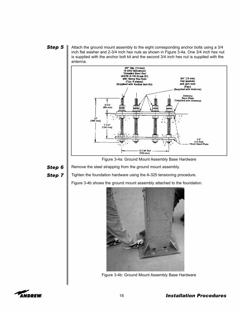
Attach the ground mount assembly to the eight corresponding anchor bolts using a 3/4inch flat washer and 2-3/4 inch hex nuts as shown in Figure 3-4a. One 3/4 inch hex nutis supplied with the anchor bolt kit and the second 3/4 inch hex nut is supplied with theantenna.
Installation Procedures
Figure 3-4a: Ground Mount Assembly Base Hardware
Remove the steel strapping from the ground mount assembly.
Tighten the foundation hardware using the A-325 tensioning procedure.
Figure 3-4b shows the ground mount assembly attached to the foundation.
Figure 3-4b: Ground Mount Assembly Base Hardware

Assembly(Without a Crane)
Step 1
Step 2
19
As stated earlier, Andrew recommends the use of a crane during this installationprocess; however, we recognize that a crane may not always be available. If a crane isnot available, the following steps provide the procedure for installing the ground mountassembly without a crane.
Carefully remove the ground mount assembly (P/N 208800-motorizable or P/N 202680-2- manual) from the packing crate. Leave the steel strapping intact to avoid disengage-ment of the panning frame from the square-tube weldment during the ground mountinstallation.
Lay the ground mount assembly on its side, in line with the anchor bolts (P/N 203314-manual or P/N 203666-motorizable) as shown in Figure 3-5.
NOTE: Ground mount positioning on the foundation is dependent upon predeterminedazimuth viewing requirements. The ground mount assembly panning-frame arm shouldbe opposite of the satellite requirement. If your site is in the Northern hemisphere, yoursatellite will be located in the South. If your site is in the Southern hemisphere, yoursatellite will be located in the North.
Installation Procedures
Figure 3-5: Ground Mount Assembly Alignment with Anchor Bolts

Step 3
20
Lift the ground mount assembly into an upright position. In the absence of a crane, it isrecommended that a minimum of two people assist in the lifting of the mount assemblyas shown in Figure 3-6a and Figure 3-6b.
Installation Procedures
Figure 3-6a: Manual Lift
Figure 3-6b: Manual Lift

Step 4
Step 5
Step 6
21
Figure 3-7: Mount Alignment/Adjustment
NOTE: You may need to adjust the mount when lifting it to ensure that the anchor boltsare aligned directly underneath the base of the ground mount assembly as shown inFigure 3-7.
Attach the ground mount assembly to the eight corresponding anchor bolts using a 3/4inch flat washer and 2-3/4 inch hex nuts as shown in Figure 3-3a.
NOTE: Ground mount positioning on the foundation is dependent upon predeterminedazimuth viewing requirements. The ground mount assembly arm should be opposite thesatellite requirement. If your site is in the Northern hemisphere, your satellite will belocated in the South. If your site is in the Southern hemisphere, your satellite will belocated in the North.
Remove the steel strapping from the ground mount assembly.
Tighten the foundation hardware using the A-325 tensioning procedure.
Figure 3-8a illustrates the ground mount assembly attached to the foundation.
Installation Procedures
Figure 3-8a: Ground Mount Assembly Base Hardware

MotorizablePedestal GroundMount Assembly
Step 1
Step 2
Step 3
Step 4
22 Installation Procedures
The ground mount assembly enables 180° positioning for selected azimuth viewing.Azimuth range coverage is ±90° divided into three 120° continuous ranges with 30°overlap. Elevation adjustment is continuous from 0 to 90°.
Position and mount 204737 azimuth tiller arm weldment to ground mount assembly asshown using 0.75 x 1.75 in. A-325 bolts and nuts. Tighten hardware per A-325 tension-ing procedure. NOTE: Mounting position of azimuth tiller arm weldment is dependentupon predetermined azimuth range requirements as shown.
Apply supplied stick lubricant to set screw threads. Loosely install 0.50 x 1.0 in. setscrews in azimuth and 0.50 x 1.50 in. set screws in elevation strut supports.
Position and mount 204754 elevation support angle assembly to ground mount asshown using 0.50 x 1.75 in. A-325 bolts, flat washers and nuts. Tighten hardware per A-325 tensioning procedure.
Loosely install supplied 0.75 x 2.00 in. A-325 bolts, flat washers and nuts in elevationsupport angle assembly. This hardware along with the upper elevation strut hardwarewill be attached to the antenna and tightened to the A-325 tensioning procedure at thetime of antenna installation.
Support Plate
1/2 x 1” Bolt andFlat Washer
3/4” ThreadedRod
3/4” FlatWasher
Pivot Block
3/4 x 1-3/4”Bolt and Nut
EL SPT AngleAssembly
AZ Tiller ArmWeldment
3/4 x 2” Bolt and Flat Washer(2 Washers per Bolt, one eachon Reflector and Mount Side)
Figure 3-8b: Ground Mount Assembly Tiller Arm Hardware
Figure 3-8c: Ground Mount Assembly Elevation Support Angle

23 Installation Procedures
1/2” FlatWasher 1/2 x 1-3/4”
Bolt and Nut
Universal Terminal5/16 x 3/4” Hex Head
Screw and Lock Washer
GroundingCable
Figure 3-8d: Ground Mount Assembly Tiller Arm Hardware
Figure 3-8e: Ground Mount Assembly Tiller Arm Hardware
Left Position -90° To +30°
Right Position -30° To +90°
Center Position -60° To +60°
Manual PedestalGround Mount
Assembly
Step 1
Step 2
24
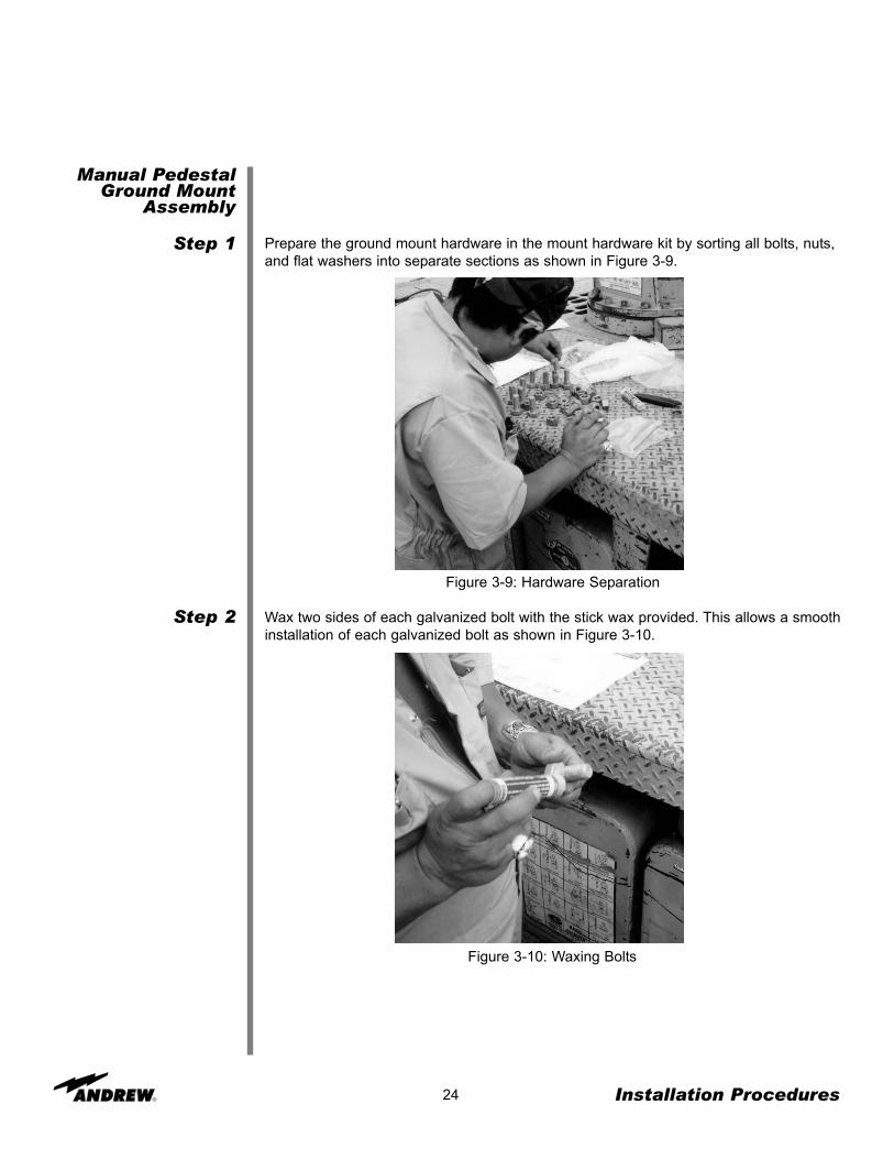
Prepare the ground mount hardware in the mount hardware kit by sorting all bolts, nuts,and flat washers into separate sections as shown in Figure 3-9.
Installation Procedures
Figure 3-9: Hardware Separation
Wax two sides of each galvanized bolt with the stick wax provided. This allows a smoothinstallation of each galvanized bolt as shown in Figure 3-10.
Figure 3-10: Waxing Bolts

Step 3
Step 4
25
Position and mount the azimuth tiller arm (P/N 203112) to the tiller-arm bracket on theleft side (facing the satellite) of the ground mount assembly. This mounting position ofthe azimuth tiller arm is dependent upon pre-determined azimuth range requirements asshown in Figure 3-11.
NOTE: The ground mount assembly enables 180 degrees positioning for selectedazimuth viewing. Azimuth range coverage is plus or minus 90 degrees, divided intothree 120 degree continuous ranges with a 30 degrees overlap. Elevation adjustment iscontinuous from 0 degrees to 90 degrees.
Installation Procedures
Figure 3-11: Azimuth Tiller Arm
Tighten the hardware using the A-325 tensioning procedure.

Step 5
26
Figure 3-12: Azimuth Tiller Arm - Final Assembly
Locate the elevation and azimuth struts (P/N 202951-2-manual) as shown in Figure 3-13.
NOTE: The azimuth strut is the strut on the right and the elevation strut is on the left.
Installation Procedures
Figure 3-13: Elevation and Azimuth Struts
An illustration of the final azimuth tiller arm is shown in Figure 3-12.

Step 6
Step 7
Step 8
27 Installation Procedures
Insert pivot blocks (P/N 205876) onto the end of the azimuth strut using lubricated 1/2inch bolt, flatwasher and hex nut as shown in Figure 3-14. A 3/4 inch flat washer shouldbe inserted between the strut and the spacer block. Tighten hardware according to theA-325 tensioning procedure.
Figure 3-14: Azimuth Strut Assembly
Slide the round strut assembly bracket (P/N 203875) on the end of the azimuth strut,and hand tighten the1/2 inch setscrews before mounting it on the ground mount assem-bly as shown in Figure 3-15.
Figure 3-15: Azimuth Strut-Bracket Assembly
Mount the second azimuth support plate (P/N 205875) pivot assembly to the rear end ofthe ground mount assembly as shown in Figure 3-16. Spacer blocks (P/N 205874) and 5/8inch hardware (hex bolt, flatwasher, hex nut) should be inserted as shown in Figure 3-10.

Step 9
28 Installation Procedures
Figure 3-16: Azimuth Pivot Assembly
Mount the azimuth strut to each bracket on the ground mount assembly as shown inFigure 3-17a and Figure 3-17b. The front and rear brackets should be aligned as shownin Figure 3-18.
Figure 3-17a: Azimuth Strut Assembly - Front

29 Installation Procedures
Figure 3-17b: Azimuth Strut Assembly - Rear
Figure 3-18 illustrates a final azimuth strut assembly mounted to the ground mountassembly.
Figure 3-18: Azimuth Strut Assembly - Final Assembly
Step 10
Step 11
30 Installation Procedures
Figure 3-19: Elevation Strut Pick Up Assembly (Top View)
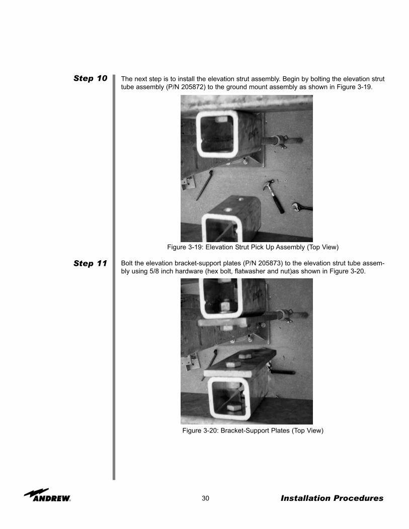
Bolt the elevation bracket-support plates (P/N 205873) to the elevation strut tube assem-bly using 5/8 inch hardware (hex bolt, flatwasher and nut)as shown in Figure 3-20.
Figure 3-20: Bracket-Support Plates (Top View)
The next step is to install the elevation strut assembly. Begin by bolting the elevation struttube assembly (P/N 205872) to the ground mount assembly as shown in Figure 3-19.

Step 12
31 Installation Procedures
The elevation strut tube assembly should now be bolted to the elevation strut bracket asshown in Figure 3-21a and Figure 3-21b.
Figure 3-21a: Elevation Strut Bracket
Figure 3-21b: Elevation Strut Bracket

Manual ActuatorAssembly
Step 1
Step 2
Step 3
32 Installation Procedures
The manual actuator assembly (P/N 207882) is used to adjust the elevation andazimuth angles of the 3.7 meter antenna. The following steps provide the procedureused to assemble and install the manual actuator assembly.
Loosely attach the manual actuator assembly (P/N 207882) to the elevation strut asshown in Figure 3-22 using clamp segments, 1/4 inch screw, lockwasher and hex nut ineach of the 12 connections.
NOTE: The drain hole should be positioned downward for proper water drainage.
Attach the base angle to the actuator (P/N 202661) using 1/2 inch screws, flatwashersand hex nuts as shown in Figure 3-22. AVOID EXCESSIVE TORQUE ON THEMOUNTING HARDWARE.
Ensure that the locking strut-support setscrew is firmly tightened on the strut assemblyas shown in Figure 3-22.
Figure 3-22a: Manual Actuator Assembly
Figure 3-22b: Manual Actuator Assembly

Step 4
Step 5
Step 6
Step 7
Manual ActuatorAssembly Removal
Step 1
Step 2
Step 3
MotorizablePedestal GroundMount Assembly
Step 1
33 Installation Procedures
Remove the two indicated strut-support setscrews, and attach the base angle to the cor-responding strut support using the supplied 1/2 inch clamping nuts and the previouslyremoved strut-support setscrews as shown in Figure 3-22b.
Securely tighten the remaining mounting hardware to achieve the clamping force.
Follow directions for “Acquiring a Satellite”.
Repeat the entire procedure for the remaining strut assembly.
After the adjustments have been made, the manual actuator should be removed. Thefollowing steps provide the procedure for the proper removal of the manual actuatorassembly.
Remove the manual actuator assembly by first removing the hardware securing theactuator to the base angle.
NOTE: The adjustment kit assembly should be removed after the antenna has beenadjusted. Store the manual actuator assembly and the corresponding hardware in a dryarea for future use.
Remove the remaining clamp segments with the corresponding hardware.
After the antenna is pointed at the satellite, tighten all azimuth and elevation setscrewsto 35 foot-pounds.
If you are assembling a motorizable pedestal mount (P/N 208800) follow the directionsfor ground mount assembly before beginning this section. The following steps providethe procedure for assembling the motorizable pedestal ground mount.
Bolt the azimuth pivot assembly (top and bottom) brackets to the ground mount assem-bly using 5/8 inch hardware (hex bolt, flatwasher and hex nut) as shown in Figure 3-23.
Figure 3-23: Azimuth Pivot Bracket Assembly

Step 2
Step 3
34 Installation Procedures
Bolt one jack to the azimuth pivot assembly using 5/8 inch hardware (hex bolt, flatwash-er and hex nut) as shown in Figure 3-24.
Figure 3-24: Jack Attachment
Unscrew the jack using a spud wrench until it meets with the front azimuth strut weld-ment as shown in Figure 3-25a.
Figure 3-25a: Jack Unscrew Procedure

Step 4
Step 5
Step 6
Step 7
35 Installation Procedures
Figure 3-25b: Azimuth Jack Attachment
Tighten the hardware using the A-325 tensioning procedure.
Lubricate the jackscrews according to the maintenance instructions.
Pull the protective boot over the jackscrew, and clamp at the end as shown in Figure 3-26.
Note: Position condensation drain holes downward.
Figure 3-26: Protective Boot Attachment
Place pivot blocks (P/N 205876) on both sides of the jackscrew ends, bolting with lubri-cated 1/2 inch hex bolt, flatwasher and hex nut as shown in Figure 3-25b.

Step 8
Step 9
36 Installation Procedures
Bolt the elevation pivot assembly brackets (P/N 208370 - left and P/N 208371 - right) tothe inside of the ground mount assembly as shown in Figure 3-27.
Figure 3-27: Elevation Pivot Bracket Assembly
Bolt the jack to the elevation pivot assembly using 5/8 inch hardware (hex bolts, flat-washers and nuts) as shown in Figures 3-28a and 3-28b.
Figure 3-28a: Elevation Jack

Step 10
Step 11
Step 12
Step 13
Step 14
37 Installation Procedures
Figure 3-28b: Elevation Jack
Loosen the clamp on the jack boot.
Unscrew the jack by using a spud wrench until the jack connects to the back of theenclosure as shown in Figure 3-28c.
Figure 3-28c: Elevation Jack Extension
Tighten the hardware using the A-325 tensioning procedure.
Lubricate the jackscrews using the maintenance procedures.
Pull the protective boot over the jackscrew, and clamp it at the end as was performedwith the azimuth jackscrew.

Embedded PipeGround Mount
Assembly
Step 1
38 Installation Procedures
Refer to Figure 3-29a for an overall view of the assembled embedded pipe groundmount assembly, reflector and subreflector assemblies.
Figure 3-29a: Typical Embedded Pipe Mount Earth Station Antenna
Attach the 104320 left side frame, to the 168 tube using four 104326 U-bolts, 100526-51M16 nuts and 100522-51 lockwashers. Add an 100536-21 M16 X 40 long bolt, 100526-51 nut and two 100522-51 lockwashers at the top of the tube, as shown in Figure 3-29b. Arrange this bolt so that a flat rests on the top of the tube.
Figure 3-29b: Left Side Frame Attachment
Ground MountAssembly
ReflectorAssembly
SubreflectorAssembly
104320Left Side Frame
M16Bolt, Lockwashers (2)
and Nut
104326U-Bolt
M16NutM16
Lockwasher

Step 2
Elevation/AzimuthStrut Assembly
Step 3
39 Installation Procedures
Attach the 104319 front frame to the left side frame as shown in Figure 3-29c. Attachthe 104325 braces to the left side by means of the U-bolts. Attach the right side frameand braces to the front frame and the right side frame to the left side frame, also shown.For all of these joints, use 100532-21 M16x40 long bolts, 100526-51 nuts and 100522-51 lockwashers. When assembly is in place, tighten to 95 N-m. (70 lbs-ft).
Figure 3-29c: Front Frame Attachment
Attach 104638 U-bracket to one end of each 301899 support pipe using 100537-87 M20 X100 hex bolt, 100526-57 M20 hex nut and 100522-57 lockwasher. Attach 301900 strutbracket to 49258 strut support using 45980-1 .625-11 x 2" long bolt and nut assembly. Note:Long bolt and nut assembly should not protrude inside diameter of 49258 strut support.Assemble strut bracket/strut support assembly to support pipe by sliding over strut withwelded tab facing 104638 U-bracket. Snug the strut support in place using 9953-15 .50-13 x 1.5" long square head screws in three places. See Figure 3-29d. Note: For eleva-tions above 75° reverse the strut support so the welded tab faces away from U-bracket.
Figure 3-29d: Elevation/Azimuth Strut Assembly
104321Right Side Frame
104325Brace
104319Front Frame
M16Nut
M16Hex Bolt
M16Lockwasher
M20 x 100Bolt, Lockwasher
and Nut
104638U-Bracket
301899-2Support Pipe
301900Strut Bracket
5/8 x 2”Bolt and Nut Assembly
49258Strut Support
1/2 x 1-1/2”Square Head Set Screw
3/4 x 3”Bolt, Flatwasher,
Lockwasher and Nut

Step 4
40 Installation Procedures
Attach the elevation strut to the top of the rear frame assembly as shown in Figure3-29e using the 100537-15 M20 x 50 bolt, 100526-57 nut and 100521-57 flatwasher.Tighten bolts to 185 N•m. (136 lbs-ft).
Figure 3-29e: Elevation Strut Attachment
Attach 301917 elevation axis weldment to the front of the frame assembly in two placesusing 100537-15 M20 x 50 long bolt, 100526-57 nut and 100522-57 lockwasher as shown inFigure 3-29f.
Figure 3-29f: Elevation Axis Weldment Attachment
M20 x 50Bolt, Flatwasher
Lockwasher and Nut
M20 x 50Bolt, Lockwasher and Nut
301917Elevation Axis
Weldment

Step 5
Step 6
41 Installation Procedures
Attach the azimuth strut to the bottom rear of the frame assembly as shown in Figure 3-29g, using the 100537-15 M20 x 50 long bolt, 100526-57 nut, 100521-57 flatwasher and100522-57 lockwasher. Attach the strut to the foundation anchor, as shown in Figure 3-29g.
Install 301931 pointer where shown in Figure 3-29g by removing the mount bolt at spec-ified location then reinstalling with 100521-51 flatwasher and pointer. Choose appropri-ate 221027 azimuth label for antenna location (Northern or Southern Hemisphere) andattach to 11809-24 clamp. Slide scale behind pipe and align with pointer and tighten.See Figures 3-29g and 3-29h.
Figure 3-29g: Azimuth Strut/Pointer Attachment
Figure 3-29h: Azimuth Label/Clamp
M20 x 50Bolt, Flatwasher
Lockwasher and Nut
M20Flatwasher,
Lockwasher andNut
M16 FlatwasherAdd Flatwasher WhenReplacing Hardware
301931Pointer
Screw 11809-24Clamp
221027Azimuth Label 180° Mark
(For Northern Hemisphere)or
0° Mark(For Southern Hemisphere)

Step 7
42 Installation Procedures
Install fine az. adjustment, attach 40188-3 thread rod to 49712-3 bracket with 9999-167.75-10 nuts and 9997-166 flatwasher. Slide threaded rod through welded tab and fastenusing 9999-167 .75-10 nuts and 9997-166 flatwasher. Note: It will be necessary to tem-porarily remove one square head bolt for fine adjusting the threaded rod. After fineadjustment it is recommended that the fine adjustment rod assembly remain in place. Ifthe threaded rod is removed the square head bolt must be replaced.Attach 49712-3 bracket to strut using 9956-67 U-bolt, 9999-109 .50-13 nut and 9974-4lockwasher. See Figure 3-29i. Repeat for elevation strut.
Figure 3-29i: Fine Azimuth Adjustment Attachment
49712-3Bracket
9997-166Flatwasher
and9999-167
3/4” Brass Hex Nut
40188-3Threaded Rod
9956-67U-Bolt,
1/2” Lockwasherand
1/2” Hex Nut

Reflector
Unpacking
Step 1
Step 2
43 Installation Procedures
The ground mount assembly is now completed with the necessary operational essen-tials. All ground mount options (such as motors) have separate instructional bulletinslocated in the parts kit that contains the option.
The next step in the installation process is the reflector assembly. Proceed to theinstructions on assembling the reflector.
The precision-spun aluminum reflector assembly enables ease of installation andensures accurate surface contour providing exceptional operating characteristics in theC-/Ku- frequency band.
NOTE: The instructions below are provided for the split-reflector style 3.7-Meter EarthStation Antenna. If you are installing the full reflector style, skip this section and proceedto Step 7.
Upon receiving your 3.7-Meter Earth Station Antenna, notice that it is delivered in awooden crate and covered with a white nylon sheath. The protective crate coveringshields the product from being damaged during the shipment process.
While unpacking the shipment, ensure that the correct parts are included by checkingthem against the packing list. The following steps provide the procedure for unpackingthe crate.
The crate arrives on site covered in a white sheath (domestic pack) or wood (exportpack). See Figure 3-30a and Figure 3-30b.
Remove the protective covering from crate.
Pry the top crate panel off with a pry bar.
Figure 3-30a: Domestic Pack

Step 3
Step 4
Step 5
Step 6
44 Installation Procedures
Figure 3-30b: Export Pack
Figure 3-30c: Unpacking
Pry the short ends of the crate off by using a pry bar and hammer as shown in Figure 3-30c.
NOTE: Notice that the parts of your order are boxed and banded to your crate. Removethese boxes by snipping the banding with tin snips.
Take the front, long side of the crate off.
Unbolt the reflector halves from the bottom of the crate. DO NOT PRY.
Find a flat area for the reflector assembly. The area must be large enough for the reflec-tor halves to lay adjacent to each other. Pieces of wood (such as 2” X 4” pieces) can bepositioned to provide a level surface for the reflector to rest on, which will preventscratching of the reflector.
Note: This area must be level or there may be problems in correctly aligning the reflector.

Step 7
Step 8
Step 9
Step 10
Assembly
Step 1
Step 2
45 Installation Procedures
Lay the first half of the reflector (which has the flash located at twelve o’clock) facedown on the blocks of wood.
Lay the second half of the reflector face down on the blocks of wood.
Unbolt the mounting ring from the crate, and set with the rest of the parts to be assem-bled.
Improve timeliness of clean up by discarding unneeded materials while unpacking thecrate. You can place all wood and unneeded materials in one area away from the instal-lation site.
Once the crate has been unpacked, you can begin assembling your Andrew earth sta-tion antenna. The reflector halves are placed next to each other to begin the assembly.The following steps provide the procedure for assembling the 3.7-Meter reflector.
Note: Figure 3-33c provided at the end of this section shows a diagram of the reflectorassembly.
Station an installer under the reflector halves to begin the assembly.
See that the joint plates are clean, and then bring the reflector halves together aligningthe joint-plate holes.
NOTE: The lip of one half fits over the other half, and the bolts match exactly whenplaced together correctly. Additionally, each half has a serial number and a red stripethat must match to ensure that you have the correct halves in the correct place.
Figure 3-31: Reflector Seam Alignment

Step 3
Step 4
46 Installation Procedures
Insert all of the joint-plate bolts, except for the socket-head shoulder bolts. All boltsshould be inserted from the same direction using a 5/16 inch hardware—flat washerunder a lock washer and nut. DO NOT TIGHTEN.
Note: DO NOT force bolts—manipulate reflector halves to allow free insertion.
At both antenna seams, loosely install three location bolts and nuts (5/16 inch hardware)adjacent to the center hole as shown in Figure 3-32.
NOTE: The installer positioned under the reflector should insert the bolts from theunderside, while the second installer inserts the flat washers under lock washers andnuts from the outside.
Figure 3-32: Seam Bolt Insertions

Step 5
47 Installation Procedures
Figure 3-33a: Alignment Bolt Insertions
Figure 3-33b: Alignment Bolt Insertions
Add the alignment hex bolts to the end holes of the joint plates as shown in Figure 3-33a (outside and inside of plate) to ensure that it is evenly aligned; and use hex bolts tofill the rest of the joint plates as shown in Figure 3-33b. THESE MUST NOT BE DRI-VEN, BUT INSERTED BY HAND.
NOTE: All bolts should be inserted from the same direction using a bolt, flatwasherunder a lockwasher and nut on joint plate and a bolt and locknut on the seam.
VERY IMPORTANT

Step 6
48 Installation Procedures
Figure 3-33d: Alignment Bolt Insertions
Tighten the hardware if the seam is correct starting from the center and working towardsthe outside of the reflector. Before tightening hardware, verify that the reflector seamgap is even along its length. Push from both directions of the seam if necessary.
NOTE: The installer positioned inside the reflector must hold the bolt head with awrench, while the nut on the outside is tightened.
Figure 3-33c: Alignment Bolt Insertions
Splice Strip and Mounting RingHardware Tapered M6 x 1.0 (25 mm)Location Bolts, Washers for MountingRing Attachment Only, and Lock Nuts
JointPlates
Seal Seam AllAround Ring
Mounting Ring
Tabs
Red LineMatch Marks
Serial No.(On Joint Plates)
Serial No.
Splice StripJoint Plate Hardware
(2) 0.31 x 1.25 (32 mm) Socket Head Shoulder Bolts(7) 0.31 x 1.25 (32 mm) Bolts Plus Flat Washers,
Lock Washers and Nuts

Step 7
49 Installation Procedures
Add the reflector-mounting ring to the assembled reflector. Notice that the notches in themounting ring fit over the reflector seam indicating where the mounting ring should beplaced. There is also a red stripe placed on the mounting ring. This red stripe must bealigned with the red stripe on the reflector as shown in Figure 3-34a. When all bolts areinserted, tighten in a clockwise sequence, tabs on the mounting ring must be flush withthe reflector as shown in Figure 3-34b.
Figure 3-34a: Mounting Ring Placement
Figure 3-34b: Mounting Ring Placement

Step 8
Step 9
50 Installation Procedures
Mount the front (P/N 202790) and back hub-mounting ring (P/N 49965) to the reflectorwith the appropriate hardware as shown in Figures 3-35a and b.
NOTE: These components are included as part of P/N 206319 Feed Hardware Kit.For K-Band Antennas, these components are included as part of P/N 301544 FeedHardware Kit (2-Port) or P/N 301515 Feed Hardware Kit (4-Port).
Figure 3-35a: Mounting and Center Rings Figure 3-35b: Mounting and Center Rings
1/4-20 x 1-1/2”Bolts, Flatwashers and Nuts
(12 places)
For equipment enclosure versions only, apply a smooth, continuous bead of RTVsealant to the inside of the reflector mounting ring to seal the reflector and the mountingring seam as shown in Figure 3-36.
Figure 3-36: Mounting Ring Sealant (Equipment Enclosure Versions Only)
Front HubMounting Ring
Reflector
Side ViewNutsLockwashersFlatwashers
Back HubMounting Ring

Alignment Test
Step 1
Step 2
Step 3
Step 4
51 Installation Procedures
Reposition the first string above the second string to check the accuracy of the first test.
NOTE: The reflector should be facing downward when the string test is performed. Theperson that is positioned under the dish should ensure that the strings are aligned cor-rectly during the test.
You have completed the assembly of the reflector. Proceed to the next page for instruc-tions on the enclosure assembly.
Figure 3-37: Reflector Alignment
As a final test of proper reflector alignment, Andrew recommends that a string test beperformed. The following steps provide the procedure for the string test.
Attach a string at the twelve o’clock position of the reflector stretching to the six o’clockposition of the reflector.
Attach a second string at the three o’clock position stretching to the nine o’clock position.
Verify its intersection to the first string as shown in Figure 3-37. If the strings touch, thenthe reflector has been correctly aligned. If they do not touch, then check all previoussteps to ensure proper assembly before continuing.
NOTE: A 1/16 inch gap is permitted.

Enclosure(Pedestal Mount
Only)
Step 1
52 Installation Procedures
The enclosure (P/N 202934A) assembly attaches to the rear of the reflector. The enclo-sure provides weather protection for RF equipment and can accommodate up to a 4-port combiner network. An example of the assembled enclosure is presented in Figure3-38a and Figure 3-38b.
Figure 3-38a: Enclosure - Final Assembly
Figure 3-38b: Enclosure - Final Assembly
Before assembling the enclosure, verify that the appropriate parts are present. The fol-lowing steps provide the procedure for the enclosure assembly.
Remove the rear covers and corresponding side panels from the enclosure assembly.
Step 2
53 Installation Procedures
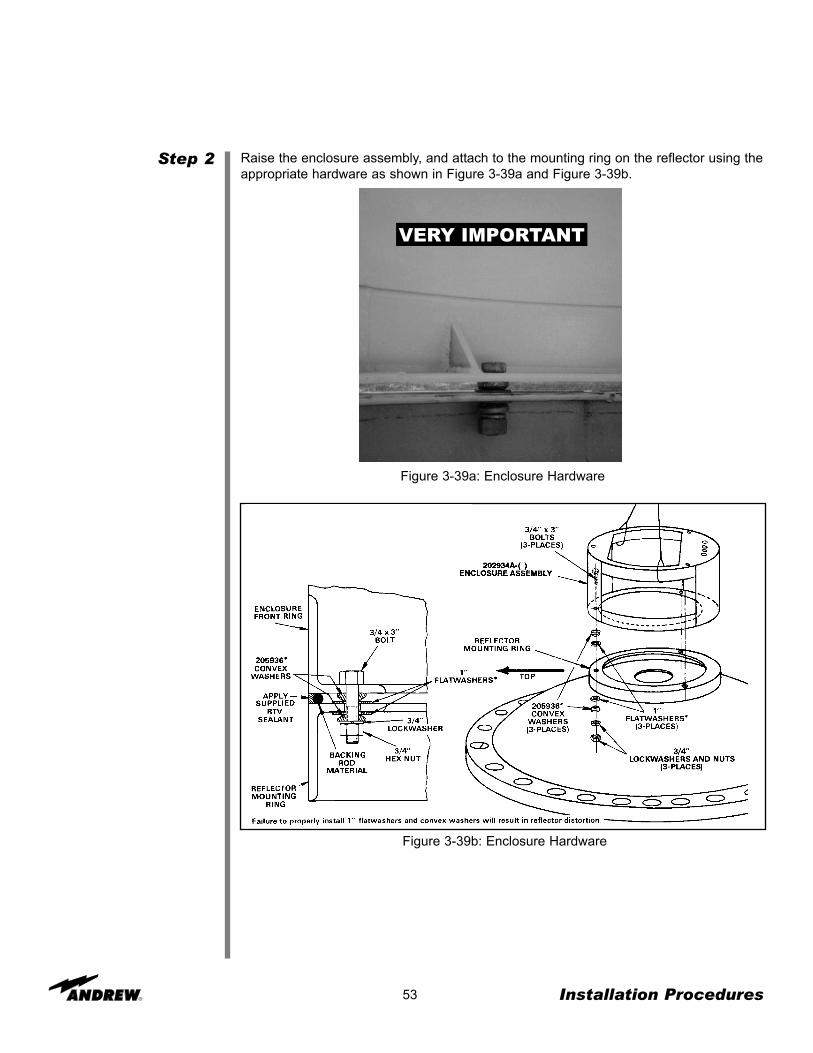
Raise the enclosure assembly, and attach to the mounting ring on the reflector using theappropriate hardware as shown in Figure 3-39a and Figure 3-39b.
Figure 3-39a: Enclosure Hardware
Figure 3-39b: Enclosure Hardware
VERY IMPORTANT

Step 3
Step 4
Step 5
54 Installation Procedures
Install the supplied sealant backing rod material around entire circumference of themounting ring/enclosure mating surfaces as shown in Figure 3-40.
Figure 3-40: Backing Rod Assembly
Securely tighten the enclosure mounting hardware using the A-325 tensioning proce-dure.
Apply the supplied RTV sealant around the outer perimeter of the reflector-mountingring/enclosure assembly junction as shown in Figure 3-41.
Figure 3-41: RTV Sealant
You have now completed the assembly of the enclosure and have mounted the enclo-sure to the reflector. Proceed to the next page for instructions on mounting the reflectorto the ground mount assembly.

Reflector-to-MountAssembly
Using a Crane
Step 1
Step 2
55 Installation Procedures
The reflector can be installed on the mount manually or by using a crane. However,Andrew recommends that this procedure be performed using a crane.
The following steps provide the procedure for installing the reflector to the mount usinga crane.
Route a sling through the upper holes in the reflector torsion box assembly, and connectthe ends using a 5/8 inch shackle as shown in Figure 3-42.
NOTE: If using a steel sling, install foam pad protection in the upper reflector torsionbox holes under the sling to avoid disfiguration of the reflector.
Route two rope tag lines through two consecutive holes in the torsion box assembly tobe used as guides when the reflector is lifted with a crane.
Figure 3-43: Safety Rope Tag Lines
Figure 3-42: Sling Placement

Step 3
Step 4
Step 5
56 Installation Procedures
Verify that all hoist assembly hardware is fully in tact before lifting the reflector to avoidpersonal injury or damage to the reflector.
Route the crane’s cable and hook from the hoist over the slings, and attach the shack-le’s hook to the crane’s hook for raising the reflector.
Position a person at the end of each tag line to guide the reflector as it is being lifted,and position another person on the mount to crank the hoist.
NOTE: The crane’s hook must be perfectly aligned with the top of the reflector’s hookso that it can be lifted straight up.
Figure 3-44a: Crane Lift
Figure 3-44b: Crane Lift
Without a Crane
Step 1
Step 2
57 Installation Procedures
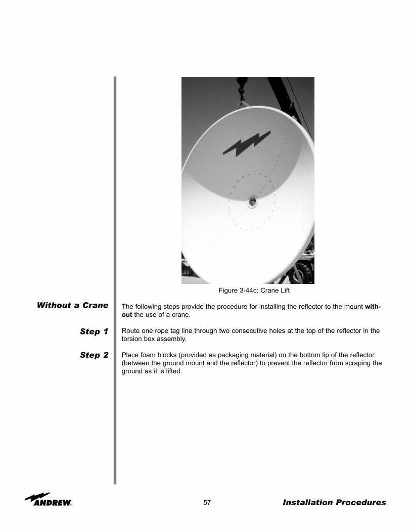
Figure 3-44c: Crane Lift
The following steps provide the procedure for installing the reflector to the mount with-out the use of a crane.
Route one rope tag line through two consecutive holes at the top of the reflector in thetorsion box assembly.
Place foam blocks (provided as packaging material) on the bottom lip of the reflector(between the ground mount and the reflector) to prevent the reflector from scraping theground as it is lifted.

Step 3
Step 4
58 Installation Procedures
Figure 3-45: Manual Lift of the Reflector to the Mount
Position one person (of the three) on the mount to guide the reflector to the mount.Refer to Figure 3-46.
Figure 3-46: Reflector to Mount
Position three people at the top of the reflector to lift the reflector on its end, facing for-ward as shown in Figure 3-45.
Step 5
Step 6
59 Installation Procedures
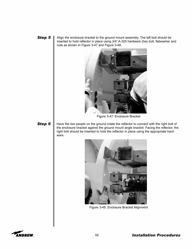
Align the enclosure bracket to the ground mount assembly. The left bolt should beinserted to hold reflector in place using 3/4” A-325 hardware (hex bolt, flatwasher andnuts as shown in Figure 3-47 and Figure 3-48.
Figure 3-47: Enclosure Bracket
Have the two people on the ground rotate the reflector to connect with the right bolt ofthe enclosure bracket against the ground mount angle bracket. Facing the reflector, theright bolt should be inserted to hold the reflector in place using the appropriate hard-ware.
Figure 3-48: Enclosure Bracket Alignment

Step 7
Step 8
Step 9
Step 10
60 Installation Procedures
Figure 3-49: Elevation Jack/Enclosure Attachment
Tighten the hardware using the A-325 tensioning procedure.
Carefully raise the reflector/enclosure assembly to the zenith (elevation = 90 degrees)position, and securely tighten the strut-support setscrews to 40 foot-pounds.
Remove all hoisting apparatus.
Extend the elevation strut or elevation jackscrew, and attach it to the top rear of theenclosure assembly as shown in Figure 3-49.

61 Installation Procedures
Figure 3-50a: Reflector to Mount
The Reflector-to-Mount components can be verified and/or clarified in the following diagram.

You have now completed the attachment of the reflector to the ground mount assembly.Proceed to the instructions on assembling and attaching the subreflector to the reflector.
62 Installation Procedures
Reflector-to-MountAssembly
Embedded PipeGround Mount
Step 1 Lift the reflector carefully onto the mount as shown in Figure 3-50b. Secure the reflectorto the mount using 100537-15 M20 x 50 long bolts, 100526-57 nuts and 100522-57lockwashers in three places. Tighten these three to 38 N•m.
Figure 3-50b: Reflector to Mount
M20 x 50Bolt, Lockwasher
and Nut
M20 x 50Bolt, Flatwasher,
Lockwasherand Nut
Elevation FineAdjustment

Subreflector
Step 1
63 Installation Procedures
Once the reflector has been assembled to the mount, the subreflector must be installed.Figure 3-51 presents a final subreflector assembly.
Figure 3-51: Installed Subreflector
The following steps provide the procedure for assembling the subreflector.
Loosely preassemble the subreflector strut weldment (P/N 202775) using the suppliedstrut angles (P/N 202776) and the 3/8 inch by 2-1/4 inch bolts, lock washers, and nutsas shown Figures 3-52a and 3-52b.
Figure 3-52a: Subreflector Strut Assembly

Step 2
64 Installation Procedures
Position and attach the subreflector-mounting ring (part of 205929 subreflector assem-bly) to the corresponding mounting holes in the strut-support plates using 3/8 inch by 1inch bolts, oversized flat washers, lock washers, and nuts as shown in Figure 3-53a andFigure 3-53b.
NOTE: Ensure that one subreflector adjustment stud is located at the six o’clock posi-tion.
Figure 3-52b: Subreflector Strut Assembly
Figure 3-53a: Subreflector Assembly

Step 3
65 Installation Procedures
Figure 3-53b: Subreflector Assembly
Attach the angle clips (P/N 49187) around the reflector perimeter at the indicated posi-tions using the appropriate hardware as noted in Figure 3-53c.
Figure 3-53c: Subreflector Assembly

Raise and attach the preassembled subreflector strut assemblies between the corre-sponding angle clips using a tag line as shown in Figure 3-54a. The angle clips shouldcorrespond with the holes in the reflector.
NOTE: Ensure that one subreflector adjustment stud is located at the six o’clock position.
Step 4
66 Installation Procedures
Figure 3-54a: Subreflector Attachment

67 Installation Procedures
SubreflectorStruts
Embedded PipeGround Mount
Assembly
Step 1
Step 2
Step 3
Step 4
Loosely preassemble the 300056 Subreflector Struts using supplied 222888 strut sup-ports and the 9963-127 3/8 inch by 2 1/4 inch bolts, 9974-63 lockwashers, and 9999-60nuts as shown in Figure 3-54b, View A.
Note: At this time it is recommended (but not necessary) to install the Subreflector, forK- & Ku-Band, see Kit #301921; for C-Band, see Kit #301939.
Attach the 49187angle clips around the reflector perimeter at the indicated positionsusing 100521-51 3/8 x 1 inch bolts, 9974-63 lockwashers and 9999-60 nuts. See ViewB in Figure 3-54b.
Figure 3-54b: Subreflector Strut Attachment
Raise and attach the pre-assembled Subreflector strut assemblies between the corre-sponding 49187 angle clips using a tag line. Attach struts between angle clips using9963-127 3/8 x 2 1/4 inch bolts, 9974-63 lockwashers and 9999-60 nuts.
Tighten strut and all hardware at this time.
222888Strut Supports
3/8 x 2-1/4”Bolt, Lockwasher
and Nut
3/8 x 2-1/4”Bolt, Lockwasher
and Nut
3/8 x 1”Bolt, Lockwasher
and Nut
300056Subreflector Strut
49187Angle Clip

SubreflectorAdjustment
Step 1
Step 2
Step 3
Step 4
Step 5
68 Installation Procedures
After the subreflector assembly has been attached to the reflector, the subreflector mustbe adjusted to ensure correct alignment. The following steps provide the procedure foradjusting the subreflector.
Position the supplied setting bar (P/N 203896 Ku-band, P/N 203896-3 C-band) ) on theouter edge of the subreflector as well as on the outer edge of the front ring (P/N202790) at the twelve o’clock (top) position.
Sweep the bar across the corresponding subreflector edge, and note the relative posi-tion.
Repeat this procedure at the six o’clock (bottom) position.
Use the noted position to indicate the required directional movement of the top portionof the subreflector aperture, which is relative to the aperture bottom using the subreflec-tor stud-adjustment hardware (3 places) as shown in Figure 3-55.
Figure 3-55: Subreflector Alignment
Repeat Steps 1-4 at the three o’clock and the nine o’clock positions to indicate the prop-er aperture side adjustment.

Step 6
Step 7
Step 8
69 Installation Procedures
Repeat the entire procedure until all four noted positions indicate that the subreflectoraperture is set parallel to the ring (P/N 202790) as shown in Figure 3-56.
Temporarily tighten the adjustment hardware until after step 10 has been completed.
Figure 3-56: Subreflector Alignment
Measure and note the distance between either outermost angle clip bolt head and thesubreflector rim.

Step 9
Step 10
Step 11
Feed System
70 Installation Procedures
Obtain the corresponding measurements from the remaining subreflector struts, andadjust the subreflector mounting hardware (4 places) to achieve a maximum differentialof 1/16 inch.
Repeat the adjustment procedure performed in Steps 1-4, until all areas of the subre-flector are uniform.
Adjust the jam nuts, and securely tighten the adjustment hardware.
Figure 3-57: Subreflector Alignment
You have now completed the subreflector assembly. By now, you can see that yourinstallation of the 3.7-Meter Earth Station Antenna is almost complete. The feed systemis the last phase of the base installation. NOTE: All antenna options (such as feed sys-tems, motors, anti-icing, etc) possess installation instructions within the individual kitscontained in the shipment.
46.925”
47.2”

Overview
Acquiring ASatellite
Step 1
Step 2
Step 3
Step 4
Step 5
Step 6
Step 7
71 Operation
After you have completed the assembly of your antenna, you are now ready to becomeoperational. In order to operate the earth station antenna, you will need to direct it to thedesired satellite adjusting both the elevation and azimuth angles appropriately. The fol-lowing procedures provide details on how to correctly position your antenna on thedesired satellite.
NOTE: Ensure that the feed system and all electronics are installed properly before pro-ceeding.
Follow the procedures listed below when acquiring the desired satellite:
Evaluate and determine the required elevation and azimuth angles for the satellite of interest.
Loosely attach the manual actuator assembly (P/N 207882) to the elevation strut asshown in Figure 3-22 using the appropriate hardware.
NOTE: The drain hole should be positioned downward for proper water drainage.
Ensure that the locking strut-support setscrew is firmly tightened on the strut assemblyas shown in Figure 3-22.
Remove the two indicated strut-support setscrews, and attach the base angle to the cor-responding strut support using the supplied 1/2 inch clamping nuts and the previouslyremoved strut-support setscrews as shown in Figure 3-22.
Securely tighten the remaining mounting hardware to achieve the clamping force.
Repeat the entire procedure for the remaining strut assembly.
NOTE: DO NOT loosen the Azimuth drive bearings.
Move the antenna to the desired azimuth angle by adjusting the manual actuator untilthe satellite signal has been spotted.
There are several procedures that may be used to properly acquire the satellite. Andrewrecommends that a spectrum analyzer be used. The following procedures provideexplanation as to how to use the spectrum analyzer.
While viewing the spectrum analyzer screen, a pure noise signal as shown in Figure 4-1will probably be observed. Additionally, some transponder signals may be observedabove the noise signal as shown in Figure 4-2.
Operation

72
Figure 4-1: Pure Noise Signal on Spectrum Analyzer
Figure 4-2: Minimum transponder Signal on Spectrum Analyzer
Operation

Step 1
Step 2
Step 3
Step 4
73
The following steps provide the procedure for acquiring a satellite.
Manually move the antenna in the azimuth (scanning back-and-forth) to achieve themaximum (greatest amplitude) transponder signals.
• Scan in one direction until the amplitude continues to diminish and then scan in theopposite direction until the same condition occurs.
• Return to the position yielding the greatest amplitude.
The maximum azimuth excursion from the original setting should not exceed plus orminus 1.5 degrees or the antenna may begin to access a different satellite.
With the antenna positioned in azimuth such that the transponder signals are maxi-mized, follow the same procedure manually moving the antenna in elevation (scanningup-and-down) to further maximize the transponder signals.
Repeat this procedure alternating between the azimuth and elevation excursions of theantenna to peak the transponder signal amplitude.
A transponder signal amplitude of 30 dB or greater from peak to average noise signalindicates the antenna is receiving the signal on the main beam. A transponder signalamplitude less than 30 dB or greater indicates the antenna is receiving the signal on aside lobe of the main beam.
With the antenna peaked on a side lobe in azimuth and/or elevation, move the antennain azimuth while observing the spectrum analyzer screen as shown in Figure 4-3.
Figure 4-3: Antenna Radiation Pattern Topographical Diagram with Plan View
Operation

Step 5
Step 6
Step 7
Step 8
74
If the signal amplitude diminishes and does not increase (position B) to the level notedwhen the antenna was peaked on the side lobe, the antenna is moving away from themain beam; reverse the direction of the antenna movement.
From the original side lobe position (position A), the signal amplitude should now dimin-ish to a null point at position C (minimum amplitude showing only signal noise) and thensymmetrically increase again to the same level at position D as noted at position A. Atthe null point (position C), the antenna is aligned with the alternate (elevation) axis. Ifthe antenna was peaked on a side lobe in azimuth, it was appropriately aligned with theelevation axis; proceed with step 6. If the antenna was peaked on a side lobe in eleva-tion, it was appropriately aligned with the azimuth axis; proceed with step 6 moving theantenna in azimuth rather than elevation.
Move the antenna in elevation while observing the spectrum analyzer screen. If the sig-nal amplitude increases, deceases and then increases again but to a lesser value, theantenna is moving in the wrong direction; reverse the direction of the antenna move-ment. From the original null point, the signal level should increase and decrease alter-nately, but with increasing amplitude until the transponder signal increases to a level ofat least 30 dB at which time the main beam. Continue to manually peak the signal to amaximum level using the azimuth and elevation adjustments.
If the antenna is aligned in azimuth and elevation (signal maximized) and 24 transpon-der signals (12 horizontal and 12 vertical) are noted, the polarization adjustment is setincorrectly and must be modified. If 12 transponder signals are noted, they may or maynot be the properly polarized signals. Therefore 24 transponder signals must be visuallynoted in order to determine the proper polarization setting.
Rotate the feed assembly clockwise until 24 transponder signals are noted and ofapproximately equal amplitude.
NOTE: It is more accurate and visually easier to minimize the alternate set of transpon-der signals rather than maximizing the transponder of interest.
Figure 4-4: Polarization at 45 degrees from Optimum Setting
Operation

Step 9
75
With all 24 transponder signals of approximately equal amplitude appearing on thespectrum analyzer screen determine the specific antenna system and satellite parame-ters. Rotate the feed assembly as required until the appropriate (odd or even) transpon-der signals are maximized.
Figure 4-5: Maximizing Odd Transponders
Figure 4-6: Optimum Polarization Setting
Operation
Manual ActuatorAssembly Removal
Step 1
Step 2
Step 3
Embedded PipeGround Mount
ElevationAdjustment
Step 1
Step 2
AzimuthAdjustment
Step 1
Conclusion
76
After you have successfully acquired the satellite and all adjustments have been made, themanual actuator should be removed. The following steps provide the procedure for the prop-er removal of the manual actuator assembly.
Remove the manual actuator assembly by first removing the hardware securing the actuator to the base angle.
NOTE: The adjustment kit assembly should be removed after the antenna has been adjust-ed. Store the manual actuator assembly and the corresponding hardware in a dry area forfuture use.
Remove the remaining clamp segments with the corresponding hardware.
After the antenna is pointed at the satellite, tighten all azimuth and elevation setscrews to 35foot-pounds.
Loosen the M20 elevation hinge bolts slightly. If coarse adjustment (i.e. more than ± 7.5)is required then loosen the three square head bolts, and u-bolt to threaded rod, makeadjustment then re-tighten U-bolt. Fine adjustment is performed by working brass nutson either side of bracket/U-bolt assembly to push or pull antenna.
Finally, tighten the M20 elevation pivot bolts to 185 N•m. (136 lbs-ft) and check all otherfasteners relating to the elevation strut.
Slightly loosen the eight M16 nuts on the main azimuth hinge u-bolts and square headbolts and nut, connecting bracket to concrete. Operate the azimuth adjustment strut inthe same manner as the elevation adjuster. When adjustment is complete, tighten thesquare head bolts and nut, connecting bracket to concrete and finally tighten the eightnuts (M16) on the u-bolts to 95 N•m. (70 lbs-ft)
Check that the fasteners on the mount are tightened to the following torque levels:
M16 - 95 N-m (70 lbs-ft)M20 - 185 N-m (136 lbs-ft)
Operation
SubreflectorAdjustment
77 Operation
After the satellite has been acquired and testing has taken place with the spectrum analyzer,the subreflector may need to be adjusted to maximize optimum performance of your anten-na. The following procedures should be followed if a subreflector adjustment is required tomaximize optimum performance.
NOTE: All INTELSAT Type Approved antennas do not require subreflector adjustment. Usingthe provided setting bar and procedures will correctly place the subreflector.
Before proceeding, azimuth and elevation patterns should be conducted to determine theadjustments that need to be made. The goal is to achieve a high peak on the main lobe andeven distances between the main lobe and sidelobes as shown in Figure 4-6.
NOTE: No adjustments should be made in the receive band.
If your pattern dictates a need to adjust the azimuth angle(the left sidelobe requires adjust-ment), the west side of the subreflector should be adjusted outward by loosening the screwson the subreflector and adjusting the left side outward. An easy way to remember thisadjustment feature is through the acronym WOLD (West Out Left Down).
If your pattern dictates a need to adjust the elevation angle(the right sidelobe requires adjust-ment), the bottom side of the subreflector should be adjusted downward by loosening thescrews between the subreflector and the struts and adjusting the bottom side of the subre-flector downward. An easy way to remember this adjustment is through the acronym BOLD(Bold Out Left Down).
Each of these adjustments should be repeated until each sidelobe is of equal distance fromthe peak of the mainlobe.
After the BOLD and WOLD adjustments have been made, it may be necessary to adjust themain lobe. The goal is to achieve a high null depth (distance between lower intersection ofsidelobes and top of main lobe) as shown in Figure 4-6.
In order to adjust the main lobe pattern characteristics ALL subreflector adjustment screwsshould be adjusted at the same degree (Note: Because the azimuth and elevation adjust-ments have been set, it is very important that the null depth adjustment be carefully conduct-ed. Be careful not to alter any previous adjustments that have been made to the subreflector.Follow the procedure listed below when adjusting the null depth of the main lobe.
C-band feeds - Adjustment screws are 3/4 X 10. Move 1 turn per 1dB of imbalance.
Ku-band feeds - Adjustment screws are 1/4 X 20. Move 1 turn per 1 dB of imbalance.
All adjustments should be continued until the desired pattern is achieved. Upon completionthe antenna should be properly aligned with the satellite for maximum performance.

Overview
General Cleaning
Electrical Parts
78 Preventive Maintenance
This section contains periodic preventive maintenance instructions for the 3.7-MeterEarth Station Antenna. Included in this section are inspection and preventive mainte-nance procedures including cleaning and lubrication, painting, and an operational volt-age/current checkout procedure deemed within the capabilities of the average stationtechnician. Refer to applicable vendor manuals for any repair procedures not included inthis section yet designated as capable off being performed in the “field” rather thanrequiring specialized facilities, tools, and/or test equipment as well as technically trainedpersonnel.
An operational checkout procedure provides an accurate indication of the overall earthstation performance and should be performed at intervals of approximately threemonths. This procedure is essentially performed during the various modes of normaloperation of the earth station. In addition, the operational checkout procedure should beperformed after any repairs or adjustments have been made, or whenever the earth sta-tion is suspected of degraded operation. If any discrepancy in performance exists andthe condition cannot be readily remedied to return the earth station to a proper operatingcondition, the appropriate troubleshooting procedures should be referenced to locate thefault. After the trouble is determined and the repairs affected, a final operational check-out procedure should be performed to verify that all discrepancies have been corrected.
The following paragraphs describe the inspection and preventive maintenance proce-dures for the earth station. These instructions include general cleaning and inspection,the preservation of metal parts and lubrication. Periodic replacement of assemblies orcomponents as a preventive measure is not required. Malfunctions of the earth stationcan be traced to components, assemblies, and parts through the use of applicable trou-bleshooting procedures.
To prevent the excessive accumulation of dust and dirt as well as the removal of suchcontaminants, thoroughly clean the equipment whenever visually inspecting the earthstation components. No special cleaning procedures are required. However, a thoroughcleaning in accordance with the following procedures is required to assure continuedtrouble-free operation.
Minor cleaning, such as the removal of dust and loose foreign particles can be accom-plished by one of the following:
• Vacuuming• Using a soft brush or lint-free cloth• Blowing out the dust and dirt with low pressure (5 to 25 psi), dry compressed air
When using air to blow off the contaminants, either avoid or be careful when directingthe air stream on delicate parts. To remove imbedded dirt, grease, or oil from electricalparts; use a 50 percent solution of isopropyl (rubbing) alcohol and apply with a soft bris-tle brush. It may be necessary to brush some parts vigorously with a stiff bristle brush toremove imbedded and hardened dirt particles. If possible, avoid excessive use of clean-ing solvent on electrical insulation. After cleaning, allow the cleaned parts to dry for 10 to15 minutes before placing the equipment into operation.
Preventive Maintenance
Mechanical Parts
Inspection
LocalControl/Motor
Drive Controller
79
Clean mechanical parts by first removing dust, dirt, and other loose contaminants with ascraper, stiff brush (bristle or wire in the case of rust or other corrosion), or cloth or com-pressed air at 25 to 40 psi. Any accumulated imbedded dirt, corrosion, grease, or oildeposits that require further cleaning may be removed with a bristle or wire brush and acleaning solvent such as trichlorethylene or equal. After cleaning, allow cleaned parts todry for 10 to 15 minutes before placing the equipment into operation.
The frequency of inspection is contingent upon the user’s individual standards and theoperational environment in which the earth station is located. However, a visual inspec-tion of the earth station components should be performed at least semi-annually. Wherethere are no established wear limits, perform a visual inspection to locate worn or dam-aged parts which could cause improper functioning of the earth station. It is recommend-ed that the mechanical and electrical inspection be performed on the assembled or par-tially disassembled equipment to determine the extent of disassembly required prior tocompletely disassembling a suspected malfunctioning component or module. In theabsence of any special inspection requirements, operational tests are the most effectivemeans in isolating parts and assemblies requiring further inspection. Any conditionnoted during inspection that may preclude continued proper operation of the earth sta-tion prior to the next scheduled inspection should be noted. The discrepant conditionshould be corrected (repaired or replaced) immediately or at the conclusion of theinspection procedure.
Inspection of the local control/motor drive controller conforms generally to standard visu-al inspection procedures on electromechanical equipment. In addition to these standardprocedures, perform the following checks and visual inspections for the specific condi-tions noted:
• Check the front panel for illegible and indistinct panel markings.
• Check the three position selector switches (Azimuth Off/Slow/Fast, Elevation-Off/Slow/Fast, and Polarization-CCW/Off/CW) for smooth operation, audible clicking ateach actuation (left to center and return) and spring return from right to center. For eachof the two position selector switches (Azimuth-East/West, Elevation-Up/Down, andLocal/Remote) check for smooth operation and audible clicking at each actuation.
• Inspect all wiring and cables for discolorization and burned insulation, dirt, breaks,security of connection and other signs of deterioration. Examine connections for dirt,flux, corrosion, and mechanical defects. Check for loose or broken lacing and cut, brittle,abraided, frayed, or cracked insulation.
• Examine connectors for corrosion, broken inserts and stripped threads. Check con-nector shells for distortion and dents, and contact pins for bends, misalignment, or otherdeformities. Check connector inserts for carbon tracking indicating arc-over.
• Check all electrical components for dirt, cracks, chips, breaks, discoloration and othersigns of deterioration and damage. A discolored, blistered, or burnt condition is evidenceof overload. Measure actual value of suspect electrical components and compareagainst specified value.
Preventive Maintenance

Antenna
80
• Check transformer for an excessive wax deposit on the surface, discoloration, or apungent odor indicative of burning vanish denoting overheating or a total breakdown.
• Check all terminal boards for broken or missing terminals and stripped threads. Checktightness of lead attaching hardware.
• Check each starter for a make-after-break provision through the release of one push-button as the alternate pushbutton is pressed.
• Check the relays and contactors for free operation of the armatures and contact con-dition. The contacts are usable even though pitted, burned, worn, or discolored. Thecontacts or contactor or relay assembly should be replaced only when the contact mate-rial has been completely torn away or worn off.
• Visually inspect all mechanical parts for freedom of operation without binding or inter-ference. Check for security of all hardware and stripped or otherwise damaged threads.Check metallic parts for corrosion, dents, distortion, and other deformation.
• Check for evidence of water inside the enclosure. If any water is in evidence, checkthat all seals are intact and if not, use a coating of RTV-108 (silicone rubber sealant) toseal any exposed electrical fitting, bolt hole, or other possible water entry to theenclosed electrical components in order to maintain a waterproof condition.
• Check or change humidity absorber.
Inspection of the antenna conforms generally to standard visual inspection proceduresperformed on electromechanical equipment. In addition to these procedures, performthe following checks and visual inspections for the specific conditions noted:
• Inspect all wiring and cables particularly the network to enclosure and enclosure tomount interfaces for discoloration and burned insulation, moisture entry, corrosion, dirt,breaks, security of connection, and other signs of deterioration. Examine connections fordirt, corrosion, and mechanical defects. Check for loose or broken lacing and cut,abraided, frayed, brittle, and cracked insulation.
• Examine connectors for corrosion, broken inserts and stripped threads. Check con-nector shells for distortion and dents, and contact pins for bends, misalignment or otherdeformities. Check connector inserts for cracks, and carbon tracking, burns or charringindicating arc-over.
• Check all electrical component for dirt, cracks, chips, breaks, discoloration, and othersigns of deterioration and damage. A discolored, blistered, or burnt condition is evidenceof overload.
Preventive Maintenance

81
• Operate the azimuth and elevation drives as well as the feed rotation in both the plusand minus direction from the local control/motor drive controller at least once everythree months during antenna down time. Check the mechanical limit switches providedat the end points stop antenna and feed movement, and limit travel to prevent structuralinterference and damage. Check the mechanical limit switches for corrosion and waterentry and the arm on each feed limit switch for free movement without binding. Be cer-tain both feed rotation limit switch arms are not distorted and ride centrally on the actu-ating cam to open their corresponding limit switch.
• Inspect the azimuth and elevation jackscrew boots for security of attachment at bothends, for abrasion, tears, cuts, brittleness and other damage that may expose thejackscrew to the environment (water, dust, etc.). Minor repairs can be made with RTV-108 silicone rubber sealant.
• Visually inspect the feed window for dirt and the feed, feed supports, feed window,and reflector for distortion, foreign object damage and environmental deterioration dueto ice and snow, dust, rain, hail, and high winds, etc. which may cause electrical compo-nent and/or structural deformation.
• Check the cable attachment to the resolvers and to the LNA or LNB’s and enclosuremount interface for security, the cable rouging for secure hanger attachment and thecable insulation for cuts, cracking, abrasion, and other deterioration. Check the LNA orLNB’s and the resolvers for a secure mechanical attachment. Ensure proper torquing ofpolarization drive gear box setscrews and appropriate tensioning of corresponding drivechain assembly, if applicable.
• Check (if applicable) that the drain holes in the bottom of the enclosure are notobstructed and there is no evidence of water accumulation. Check the enclosure doorsfor proper closure and that the door seals are intact, not torn, abraided or otherwisedamaged. Check that all other seals are intact and if not, use a coating of RTV-108 (sili-cone rubber sealant) to seal any exposed electrical fitting, bolt hold, or other possiblewater entry to electrical components in order to maintain a weatherproof condition. If theenclosure is provided with a vent fan, check for free operation of the fan blade. The fanbearings are permanently lubricated; any binding, abnormal noise or vibration necessi-tates replacement of he fan assembly. Check and replace the fan filter element if itappears dirty or obstructed with dust.
• Check for the appearance of surface lubricants that will cause the accumulation of dirtand grime. Clean off all excess surface lubricants with a cloth and if required, a clothdampened not wetted with trichlorethylene, or equal.
• Visually inspect all mechanical parts for freedom of operation with no misalignment,binding or interference. Check all cabling for sufficient slack to prevent cable strain aswell as adequate restraint to prevent abrasion or chaffing during antenna and feedmovement.
Preventive Maintenance

Drive SystemVoltage and
Current Checks
Step 1
Step 2
Step 3
82
• Check security of antenna mounting and interconnecting assembly hardware. Be cer-tain all electrical grounding connections (including cross-axis grounding straps) areintact and secure, not corroded or broken. Thoroughly clean any noticeable corrodedportions of grounding cables, unplated portion of universal terminals and correspondingmounting surfaces using a wire brush. Replace rather than tighten any loose A-325structural hardware. The hardware distorts at initial installation and once loosened willnot maintain the required high strength friction connection. All other assembly and instal-lation hardware should be tightened to its original torqued condition. When installingnew structural hardware, do not use a wrench with a lever arm longer than two feet.
• Examine painted aluminum and galvanized surfaces and tough-up where required.
At the conclusion of the installation procedure prior to turning the system over to the sta-tion facility, an installation acceptance check off sheet was prepared and duly signed offif installed by Andrew crew. Part of this check off included voltage readings retaken todetermine if proper voltage was available. Current readings were also taken as a refer-ence for future comparison to serve as a troubleshooting aid in determining possibleequipment degradation and shortened life. Any current reading taken during the follow-ing procedure that varies by more than five percent from the pre-established referencevalues necessitates troubleshooting the particular system involved to determine thecause and required corrective action.
Approximately every three months and during a period of down time, disconnect asapplicable the RF transmitter and all power supplies. The main disconnect switch in themain load center box at the antenna site must be in the ON position and theLOCAL/REMOTE switch in the local control motor drive controller must be in the LOCALposition.
Open the outer local control/motor drive controller door at the antenna site to gainaccess to the conductors supplying power to the azimuth, elevation, and polarizationdrive motors.
NOTE: During the following procedures, the antenna drives (azimuth, elevation, andpolarization) will be powered to rotate the antenna and feed in both directions of travel.Check that this condition can be tolerated from a safety as well as an operational stand-point, and that the electrical limits are not reached before the testing is concluded.Reaching an electrical limit before concluding a test necessitates rotating the antenna orfeed in the opposite direction a sufficient distance to permit retesting in the desireddirection.
Turn the FEED CCW/OFF/CW switch to either the CW or CCW position and while thefeed is rotating, carefully use a clamp on ammeter in accordance with the ammeter man-ufacturer’s instructions to take current readings off each of the three conductors (phases)connected to the load side of the polarization motor circuit breaker. Record the currentdraw in the equipment log and compare the readings to the reference values entered inthe installation/acceptance check off. If the readings differ by more than five percent,refer to appropriate troubleshooting information and perform applicable corrective action.Then take voltage readings off each of the three conductors; the readings should agreewith each other within two percent. Turn the FEED CCW/OFF/CW switch to OFF.
Preventive Maintenance

Step 4
Step 5
Step 6
Step 7
Step 8
Step 9
Pedestal MountBearing PadAdjustment
Step 1
Step 2
Step 3
Step 4
Step 5
83
Repeat preceding step (3) with the FEED CCW/OFF/CW switch in the alternate operat-ing position.
Turn the AZIMUTH EAST/WEST switch to either position and while the antenna is rotat-ing, carefully use a clamp on ammeter in accordance with the ammeter manufacturer’sinstructions to take current readings off each of the three conductors (phases) connect-ed to the load side of the azimuth drive motor circuit breaker. Record the current draw inthe equipment log and compare the readings to the reference values entered in theinstallation/acceptance check off. If the readings differ by more than five percent, refer toappropriate troubleshooting information and perform applicable corrective action. Thentake voltage readings off each of the three conductors; the readings should agree witheach other—within two percent. Turn the AZIMUTH switch to OFF.
Repeat steps (5) with the AZIMUTH EAST/WEST switch in the alternate operating posi-tion.
Turn the ELEVATION DOWN/UP switch to either position and while the antenna is rotat-ing, carefully use a clamp on ammeter in accordance with the ammeter manufacturer’sinstructions to take current readings off each of the three conductors (phases) connect-ed to the load side of the elevation drive motor circuit breaker. Record the current drawin the equipment log and compare the readings to the reference values entered in theinstallation/acceptance check off. If the readings differ by more than five percent, refer toappropriate troubleshooting information and perform applicable corrective action. Thentake voltage readings off each of the three conductors; the readings should agree witheach other within two percent. Turn the ELEVATION switch to OFF.
Repeat steps (7) with the ELEVATION DOWN/UP switch in the alternate operating posi-tion.
If all voltage and current readings are within tolerance, close the local control/motordrive controller inner door and place the LOCAL/REMOTE switch in the REMOTE posi-tion to return antenna control to the studio. Then close and lock the outer localcontrol/motor drive controller door.
The bearing pad (within the pedestal mount) adjustment rods/bolts require yearly adjust-ment and verification of torque value. With the antenna at zenith (90 degrees), followthe procedures presented below:
Loosen jam nuts on all adjustment rods/bolts.
Torque the upper adjustment rod evenly to 40 - 45 foot-pounds. Then torque the loweradjustment rod evenly to 40 - 45 foot-pounds.
Torque the upper adjustment bolt evenly to 40 - 45 foot-pounds. Then torque the loweradjustment bolt evenly to 40 - 45 foot-pounds.
Repeat steps 2 and 3 verifying all adjustment rods/bolts are evenly torqued within thelimits specified.
Tighten the jam nuts.
Preventive Maintenance

Preservation ofComponent Parts
Aluminum Parts
GalvanizedSurfaces
Lubrication
84
When preserving the component parts, refer to the following paragraphs in this section.
Remove all loose paint and corrosion by scraping, wire brushing, or using steel wool. Ifusing steel wool near the feed window, make sure that none remains on the feed hornwindow. Edges of existing paint can be blended with the metal surface by using a finegrit sandpaper. Wipe the surface to be painted with a soft rag dampened in trichlorethyl-ene, lacquer thinner or equal. Be certain to remove all loose paint, corrosion, imbeddeddirt, grease, and oil deposits or the paint will not adhere to the surface. Lacquer thinnerwill dissolve paint if applied heavily and rubbed vigorously. The reflector may be washedwith plain water if necessary. Do not use bleach, soap solutions, or kerosene as it is dif-ficult to remove the residue. Allow the cleaned surface to dry thoroughly before priming.
Prime the cleaned surface by applying zinc chromate primer. The primer can be appliedwith a brush, roller, or pressurized spray. If necessary, thin the primer with lacquer thin-ner to the proper consistency. Feather primer onto adjacent painted surfaces;. Allowprimer to thoroughly dry before applying the finish paint coat.
Paint all RF surfaces, such as the inside of the main reflector and subreflector with ahigh-reflectance white paint. This type of paint disperses light rays, reducing the focus-ing effect of the sun’s radiation, thereby reducing heat build-up caused by the focusedsun’ rays on the feed system. Rear surfaces of the reflector and subreflector may bepainted with a flat white enamel paint. The paint can be applied with a brush, roller, orpressurized spray. If necessary, thin the paint with the appropriate thinner to the properconsistency. Thoroughly paint over the primed surfaces and blend with the existingpainted surface.
Remove all loose paint and corrosion by scraping, wire brushing, or using steel wool.Edges of existing paint can be blended with the metal surface by using a fine grit sand-paper. Wipe the surface to be painted with a soft rag dampened in trichlorethylene, lac-quer thinner, or equal. be certain to remove all loose paint, corrosion, imbedded dirt,grease, and oil deposits or the paint will not adhere to the surface. Lacquer thinner willdissolve paint if applied heavily and rubbed vigorously. Do not use bleach, soap solu-tions, or kerosene as it is difficult to remove the residue. Allow the clean surface to drythoroughly before painting.
Paint the cleaned surface with a zing-rich paint. The paint can be applied with a brush,roller, or pressurized spray. If necessary, thin the paint with the appropriate thinner tothe proper consistency. Thoroughly paint over the cleaned surface and blend with theexisting painted surface.
For long life and trouble-free operation be certain not to extend the lubrication schedulebeyond the frequency recommended in Table 5-1. The frequency should be shortened ifthe antenna is subjected to an adverse environment (e.g., high temperature, extendedperiods of rainfall, high humidity, dust storms, etc). Any component or part should beimmediately be lubricated if during inspection or operation, rough, jarring, or intermittentmotion is noted, or if squeaky or other unusual noises are heard. Lubrication is requiredon all metal-to-metal rolling or sliding parts. Us the lubricants recommended. Do notover lubricate. Over lubrication can often be as damaging as under lubrication. Prior tothe application of lubricant to any parts, use a clean cloth and/or bristle brush and
Preventive Maintenance

Jackscrews/Motors
GearMotor/Housing Fill
DrainRequirements
85
remove any old lubricant to prevent an excessive build-up. Remove indicated accessplugs from square tube weldment and apply lubricant to panning frame tube assemblyand corresponding thrust pads. Securely replace access plugs in square tube weldment.Be certain to remove any protective caps and clean off each lubrication fitting prior toinjecting fresh grease. The elevation and azimuth jackscrew assemblies are equippedwith a grease fitting and corresponding pipe plug on opposite sides of the jack housing.Remove the appropriate pipe plug and fill with with grease until lubricant seeps from thepipe plug opening. Replace and securely tighten pipe plug.
The following is a list of the lubricant characteristics:
• Mobil Temp SHC32 A non-soap hydrocarbon fluid type grease. Operating tempera-ture range is -65 degrees to 350+ degrees Fahrenheit (-54 degrees to 177+ degrees Celsius).
• Mobil SHC624 A low temperature synthetic oil for worm gear reducers. Operating temperature range is -40 degrees to 125+ degrees Fahrenheit (-40 degrees to 52+ degrees Celsius).
• Lightning Grease A grease lubricant containing molybdenum disulfide. Operating temperature range is -85 degrees to 300+ degrees Fahrenheit (-29 degrees to 149+ degrees Celsius).
Periodically inspect lifting screws on jackscrew assemblies to ensure adequate lubrica-tion. Loosen Jackscrew boot clamps to expose the lifting screw assembly. Fully extendjackscrew assembly being careful not to exceed preset mechanical limits. Brush thincoating of Mobil SHC32 grease on exposed lifting screw. Replace boot and attach corre-sponding boot clamps. If lifting screw is rusty, remove existing lubricant with solvent andwire brush rusted area. Rinse with solvent and apply fresh grease.
Peiordically inspect and remove dust or dirt deposits from the motor housings to avoidhindering the heat exchange with the ambient air. Slight dirt accumulation on the airvent screw through splash oil cannot be avoided; however, keep vent screw clean toensure proper pressure compensation.
Lube points 2 and 4, shown in Table 5-1, require removal of the indicated drain plugsand collecting/measuring the amount of SHC624 drain oil using measuring cup. Thespecified amount of oil must be added to the gear motor/housing (after installing thedrain plug) via the fill/vent plug opening using supplied funnel. Addition of the oilrequires use of an appropriate filling utensil. Use of a modified level stick will not cor-rectly gauge the appropriate amount of oil in the gear housings.
Preventive Maintenance

86
Lube Service Lube Quantity AndrewPoint Parts to be Lubricated Action Frequency Type Type /Points Number
1 Elevation jackscrew housing Lubricate Every 3 Pressure SHC32 1 49208months Fitting
2 Elevation gear motor housing Inspect Monthly Pipe Plugs SHC624 10 ounces 47497fill and drain
Change Every 3months
3 Azimuth jackscrew housing Lubricate Every 3 Pressure SHC32 2 49208months Fitting
4 Azimuth jackscrew gear Inspect Monthly Pipe Plugs SHC624 10 ounces 47497housing fill and drain
Change Every 3months
5 Panning frame tube assembly Lubricate Every 3 Brush Lightning Surface 207912and thrust pads months On Lubricant Coverage
Table 5-1: Antenna Lubrication Chart
Inspection requires checking for visible signs of oil leakage, draining, replacing, andadding oil to ensure appropriate oil level requirements. Excessively dirty oil will requirefresh oil replacement. If oil leakage is found to be excessive, refer to appropriate trou-bleshooting information and perform applicable corrective action. Periodic inspectionprocedures can be less frequent after first or second scheduled inspections.
Initial oil change requirements include flushing gear boxes with a standard cleaningagent.
Preventive Maintenance