Embed Size (px)
Citation preview
WSRC-STI-2007-00427 Rev. 1
U.S. Department of Energy Office of Environmental Management Paducah Gaseous Diffusion Plant (PGDP)
Review Report: Building C-400 Thermal Treatment 90% Remedial Design Report and Site Investigation, PGDP, Paducah Kentucky 15 August 2007
Paducah Gaseous Diffusion Plant (PGDP)Paducah KY
Paducah Gaseous Diffusion Plant (PGDP)Paducah KY
Prepared for: Office of Groundwater and Soil Remediation Office of Engineering and Technology
Review Report – C-400 Thermal Remediation PGDP WSRC-STI-2007-00427 rev. 1
Cover Photo: Oblique view overhead photograph of the Department of Energy
Paducah Gaseous Diffusion Plant near Paducah KY. The TCE source area targeted for thermal treatment is located near the center of the photograph. .
DISCLAIMER
Preparation of this report was coordinated by Washington Savannah River Company (WSRC) for the United States Department of Energy (US DOE) under Contract No. DE-AC09-96SR18500. Careful effort was made by the authors to assure the accuracy of the contents and interpretation. However, the USDOE nor WSRC, nor any of their employees makes any warranty, expressed or implied, or assumes any legal liability for accuracy, completeness, or usefulness, of information, apparatus, or product or process disclosed herein or represents that its use will not infringe privately owned rights. Reference herein to any specific commercial product, process, or service by trade name, trademark, name, manufacturer or otherwise does not necessarily constitute or imply endorsement, recommendation, or favoring of same by WSRC or by the United States Government or any agency thereof. The views and opinions of the authors expressed herein do not necessarily state or reflect those of the United States Government or any agency thereof.
Printed in the United States of America
Prepared For
U.S. Department of Energy

Review Report – C-400 Thermal Remediation PGDP WSRC-STI-2007-00427 rev. 1 Page i of vi
U.S. Department of Energy Office of Environmental Management
Review Report: Building C-400 Thermal Treatment 90% Remedial Design Report and Site Investigation, PGDP, Paducah Kentucky 15 August 2007 Authors: Dr. Brian Looney, Savannah River National Laboratory: Review Technical Lead Dr. Jed Costanza, Georgia Institute of Technology Dr. Eva Davis, U.S. Environmental Protection Agency Dr. Joe Rossabi, Redox-Tech, LLC Dr. Lloyd (Bo) Stewart, Praxis Environmental Technologies, Inc. Dr. Hans Stroo, HGL, Inc. Prepared for: Office of Groundwater and Soil Remediation Office of Engineering and Technology Ms. Beth Moore, DOE Independent Technical Review Project Manager Technical coordination and evaluation for this effort were provided by the Savannah River National Laboratory (Washington Savannah River Company (WSRC)) for the United States Department of Energy under Contract No. DE-AC09-96SR18500. Independent experts were contracted by the Legin Group in support of the U.S. Department of Energy EM22.

Review Report – C-400 Thermal Remediation PGDP WSRC-STI-2007-00427 rev. 1 Page ii of vi
{blank page}

Review Report – C-400 Thermal Remediation PGDP WSRC-STI-2007-00427 rev. 1 Page iii of vi
Review Report: Building C-400 Thermal Treatment 90% Remedial Design Report and Site Investigation, PGDP, Paducah Kentucky Table of Contents Executive Summary 01 Synopsis of Recommendations 02 1.0 Background 06 2.0 Remedial Design Review Goals 11 3.0 Review Team and Process 11
3.1 Review team composition 11 3.2 Site visit, presentations and persons contacted 12
4.0 Lines of Inquiry 13 5.0 Remedy Review Findings and Recommendations 14
5.1 Site investigation and target zone delineation 14 5.2 Performance objectives 24 5.3 Project and design topics 31 5.4 Health and Safety 44 5.5 Cross cutting and independent cost evaluation 46
6.0 Consolidated List of Recommendations 52 7.0 References 58 Appendices A. ITR Team Members 59 B. Evaluation of RDSI Data using GMS Cross Sections 72 C. Graphs of Trends and Concentrations in Monitoring
Wells in the Vicinity of the PGDP C-400 Building 78 D. Modeling and Engineering Evaluation 84 E. Cost Evaluation 96

Review Report – C-400 Thermal Remediation PGDP WSRC-STI-2007-00427 rev. 1 Page iv of vi
Review Report: Building C-400 Thermal Treatment 90% Remedial Design Report and Site Investigation, PGDP, Paducah Kentucky List of Figures 1. Plumes of TCE in the groundwater (RGA) underlying PGDP 07 2. TCE source material in the vicinity of Building C-400 08 3. Hydrostratigraphy near C-400 at PGDP 09 4. MIP boreholes and ECD response overlaying interpolation of PID responses
in the SE source zone area (looking N) 16 5. MIP boreholes and ECD response overlaying interpolation of PID responses
in the SE source zone area (looking W) 17 6. MIP boreholes and ECD response overlaying interpolation of PID responses
in the SW source zone area (looking N) 18 7. MIP boreholes and ECD response overlaying interpolation of PID responses
in the ESE source zone area (looking N) 19 8. Monitoring wells in the vicinity of the C-400 Building at PGDP 21 9. Idealized heating profile for a simple saturated system containing TCE
DNAPL and water 26 10. Simplified schematic of convection processes during ERH of the permeable
portion of the treatment zone 32 11. Estimated shape of steam injection front in the RGA 35
Review Report – C-400 Thermal Remediation PGDP WSRC-STI-2007-00427 rev. 1 Page v of vi
List of Acronyms DNAPL Dense Nonaqueous Phase Liquid DOE U. S. Department of Energy ECD Electron Capture Detector ERH Electrical Resistance Heating ITR Independent Technical Review LOI Line of Inquiry MIP Membrane Interface Probe PGDP Paducah Gaseous Diffusion Plant PID Photoionization Detector PPPO Portsmouth/Paducah Project Office RDR Remedial Design Report RDSI Remedial Design Support Investigation RGA Regional Gravel Aquifer ROD regulatory Record of Decision SVE Soil Vapor Extraction TCE trichloroethylene UCRS Upper Continental Recharge System VOCs Volatile Organic Compounds

Review Report – C-400 Thermal Remediation PGDP WSRC-STI-2007-00427 rev. 1 Page vi of vi
{blank page}

Review Report – C-400 Thermal Remediation PGDP WSRC-STI-2007-00427 rev. 1 Page 1 of 100
Review Report: Building C-400 Thermal Treatment 90% Remedial Design Report and Site Investigation, Paducah Kentucky Executive Summary On 9 April 2007, the U.S. Department of Energy (DOE) Headquarters, Office of Soil and Groundwater Remediation (EM-22) initiated an Independent Technical Review (ITR) of the 90% Remedial Design Report (RDR) and Site Investigation (RDSI) for thermal treatment of trichloroethylene (TCE) in the soil and groundwater in the vicinity of Building C-400 at the Paducah Gaseous Diffusion Plant (PGDP). The general ITR goals were to assess the technical adequacy of the 90% RDSI and provide recommendations sufficient for DOE to determine if modifications are warranted pertaining to the design, schedule, or cost of implementing the proposed design. The ultimate goal of the effort was to assist the DOE Paducah/Portsmouth Project Office (PPPO) and their contractor team in “removing” the TCE source zone located near the C-400 Building. This report provides the ITR findings and recommendations and supporting evaluations as needed to facilitate use of the recommendations. The ITR team supports the remedial action objective (RAO) at C-400 to reduce the TCE source area via subsurface Electrical Resistance Heating (ERH). Further, the ITR team commends PPPO, their contractor team, regulators, and stakeholders for the significant efforts taken in preparing the 90% RDR. To maximize TCE removal at the target source area, several themes emerge from the review which the ITR team believes should be considered and addressed before implementing the thermal treatment. These themes include the need for:
• Accurate and site-specific models as the basis to verify the ERH design for full-scale implementation for this challenging hydrogeologic setting
• Flexible project implementation and operation to allow the project team to respond to observations and data collected during construction and operation
• Defensible performance metrics and monitoring, appropriate for ERH, to ensure sufficient and efficient clean-up
• Comprehensive (creative and diverse) contingencies to address the potential for system underperformance, and other unforeseen conditions
These themes weave through the ITR report and the various analyses and recommendations. The ITR team recognizes that a number of technologies are available for treatment of TCE sources. Further, the team supports the regulatory process through which the selected remedy is being implemented, and concurs that ERH is a potentially viable remedial technology to meet the RAOs adjacent to C-400. Nonetheless, the ITR team concluded that additional efforts are needed to provide an adequate basis for the planned ERH design, particularly in the highly permeable Regional Gravel Aquifer (RGA), where sustaining target temperatures present a challenge. The ERH design modeling in the 90%

Review Report – C-400 Thermal Remediation PGDP WSRC-STI-2007-00427 rev. 1 Page 2 of 100
RDR does not fully substantiate that heating in the deep RGA, at the interface with the McNairy formation, will meet the design goals; specifically the target temperatures. Full-scale implementation of ERH to meet the RAOs is a challenge in the complex hydrogeologic setting at PGDP. Where possible, risks to the project identified in this ITR report as “issues” and “recommendations” should be mitigated as part of the final design process to increase the likelihood of remedial success. The ITR efforts were organized into five lines of inquiry (LOIs):
1. Site investigation and target zone delineation 2. Performance objectives 3. Project and design topics 4. Health and safety 5. Cross cutting and independent cost evaluation
Within each of these LOIs, the ITR team identified a series of unresolved issues – topics that have remaining uncertainties or potential project risks. These issues were analyzed and one or more recommendations were developed for each. In the end, the ITR team identified 27 issues and provided 50 recommendations. The issues and recommendations are briefly summarized below, developed in Section 5, and consolidated into a single list in Section 6. The ITR team concluded that there are substantive unresolved issues and system design uncertainties, resulting in technical and financial risks to DOE. If PPPO and their remedial team objectively evaluate each issue and recommendation to formulate a project risk mitigation strategy toward remedial implementation, the ITR team believes that issues can be resolved to maximize the potential to successfully achieve the regulatory goals. The review recommendations are intended to maximize contaminant extraction through improvements to the design, assure defensible performance metrics to measure progress and system shutdown, save cost, and improve the probability of successful full-scale implementation. The ITR team gratefully acknowledges the efforts of the PGDP project team and their support of our review process and commends the PGDP project team for their openness and responsiveness to the review comments and information requests. As noted in various sections of the body of the report, several of the initial ITR team recommendations (those provided in the outbriefing and follow-up interactions) have already been addressed by PGDP during the writing of this review report. Synopsis of Recommendations The ITR team considers the highest priority recommendations as those summarized in this Executive Summary that are recurring issues, or themes of the review. Specifically, several recommendations highlight the need to improve the design model basis, and its verification for scale-up to the field. Given that the model results are the primary basis for the remedial system design, and the contractor team expressed confidence in the

Review Report – C-400 Thermal Remediation PGDP WSRC-STI-2007-00427 rev. 1 Page 3 of 100
heating models, the ITR team recommends that the contractor team stand behind the heating performance predictions for the remedial system. The sections below provide a brief introduction to the ITR recommendations, and are arranged according to the LOI. 1. Site investigation and target zone delineation – The target treatment zones delineate a substantial TCE source area, and are consistent with the regulatory Record of Decision (ROD). The data provide an appropriate initial basis for design and operation. Nevertheless, significant unresolved issues were identified and uncertainties remain. The primary characterization recommendations include:
• Expanding the target treatment zones in a few critical locations • Sampling verification during system installation to allow for reasonable
adjustments in treatment zone placement • Additional groundwater monitoring wells in a few critical locations • Future sampling downgradient of the treatment zone, and beneath Building C-400
2. Performance objectives – The ITR team provided a number of recommendations related to performance metrics. The ROD selected ERH as an Interim Remedy to “permanently and significantly reduce the mass of contaminants in the C-400 Building area source zone.” Importantly, the ROD does not require the interim remedial action to reduce concentrations of TCE to the maximum concentration limits typically allowable in unrestricted groundwater. The ROD further states that, “Operation of the Electrical Resistance Heating array would cease when the monitoring system indicates that heating has stabilized in the subsurface and the contaminant recovery diminishes to a point where significant additional decreases in this rate of recovery are not anticipated (i.e., the rate of removal of TCE and other VOCs becomes asymptotic).” When developing the design, asymptosis was defined as achieving 400 parts per million volume in the collected vapor phase and the thermal performance target was set to the “co-boiling” temperature of a TCE and water mixture. The ITR team believes that these metrics should be refined and improved based on technical considerations. The primary ITR recommendations for this LOI include:
• Evaluating the TCE content in liquid recovered during thermal treatment • Developing additional technically-based and robust metrics • Increasing the heating target in the saturated zone beyond the co-boiling point of
TCE (temperatures at or below the co-boiling point do not assure source removal) • Incorporate broader PGDP exit strategy goals when setting performance metrics
for the thermal treatment action. The ITR team cautioned that it may take many years to observe a decrease in TCE groundwater concentrations in the downgradient plume after executing the proposed ERH treatment of the Building C-400 TCE source zone. This is because of the large mass of TCE already in the plume and the potential existence of TCE sources not addressed by this treatment.

Review Report – C-400 Thermal Remediation PGDP WSRC-STI-2007-00427 rev. 1 Page 4 of 100
3. Project and design topics – Successful full-scale field implementation of ERH at PGDP is challenging, given the complex hydrogeologic setting and lessons learned from the ERH treatability study completed in 2003. The system is designed to treat TCE present in the vadose and saturated zones; both zones have a wide range of hydraulic and electrical properties. The ITR team believes that remedial success in these zones with ERH warrants deployment in a manner that is:
• Responsive and flexible to unforeseen field conditions that may be encountered • Performed with equipment having sufficient range to implement contingencies • Monitored strategically at various points within the engineered system, and in
media such as vapor, groundwater, and soil • Based on site-specific and verified design models that assist in a robust
implementation The ITR team recommends either a phased approach to implementation or an alternative approach to mitigate the risk of moving to full scale. In addition the team recommends staged start up and shut down sequences that are based on technical and logistical considerations. A number of project and design topics, including elimination of the steam heating cell, are addressed in the ITR report. As discussed in previous LOI sections, there are unresolved issues and uncertainties related to the design model presented in the 90% RDR. One issue of concern is that the heating may not effectively target the deeper portion of the RGA, where a significant fraction of the TCE is present. The challenge for any thermal treatment technology is one of buoyancy, in this case from the tendency of water (or steam) to rise as it heats thus limiting the zone of influence of the desired target temperatures to a few feet from the electrodes at the bottom of the formation. This critical design issue warrants resolution prior to remedy implementation. Finally, the ITR team recommends additional contingency actions for scenarios of system underperformance; these recommendations are intended to supplement the contingency evaluation included in the 90% RDR.
4. Health and safety – In general, the information provided by PGDP suggests that reasonable site infrastructure, policies, and training are in place to protect health and safety, including:
• Existing site procedures and operational readiness systems • Proposed electrical safety and walk around checks during ERH operations • Chemical training requirements and documentation plans • Lock-out-Tag-out for energized, pressurized and chemical systems
The ITR team identified that the design package did not address system interlocks, safety systems, and contingencies to handle the presence of co-contaminants in soil and groundwater in sufficient detail.
Review Report – C-400 Thermal Remediation PGDP WSRC-STI-2007-00427 rev. 1 Page 5 of 100
5. Cross cutting and independent cost evaluation – The ITR team determined that the estimated cost for ERH treatment at Building C-400 is within the range of thermal treatment costs at other federal sites on a per treatment volume and per electrode basis. The estimated remedial costs are near the upper end of the historical range; therefore, the remedial project team is encouraged to work toward further cost refinement and reduction opportunities as project plans are finalized. The costs for waste management and disposition are a significant fraction of the overall estimated project costs. Thus, the ITR team recommends careful classification of solid wastes to minimize disposal costs, and consideration of solvent recycling, rather than disposal, for recovered TCE. The ITR team recommends more complete documentation of the ERH vendor selection and development of a communication plan. The findings and recommendations in the body of the report, supplemented by appendices, are intended to aid the PGDP project team in executing a successful cleanup and in collaborating with their regulators.
Review Report – C-400 Thermal Remediation PGDP WSRC-STI-2007-00427 rev. 1 Page 6 of 100
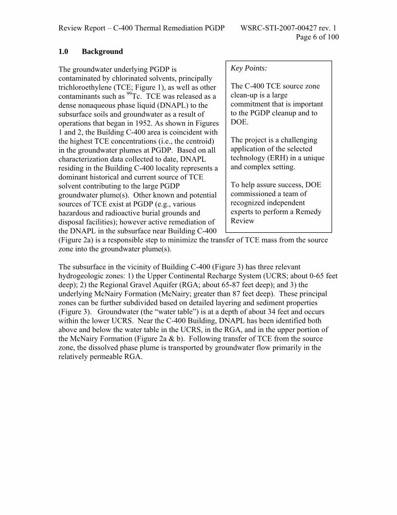
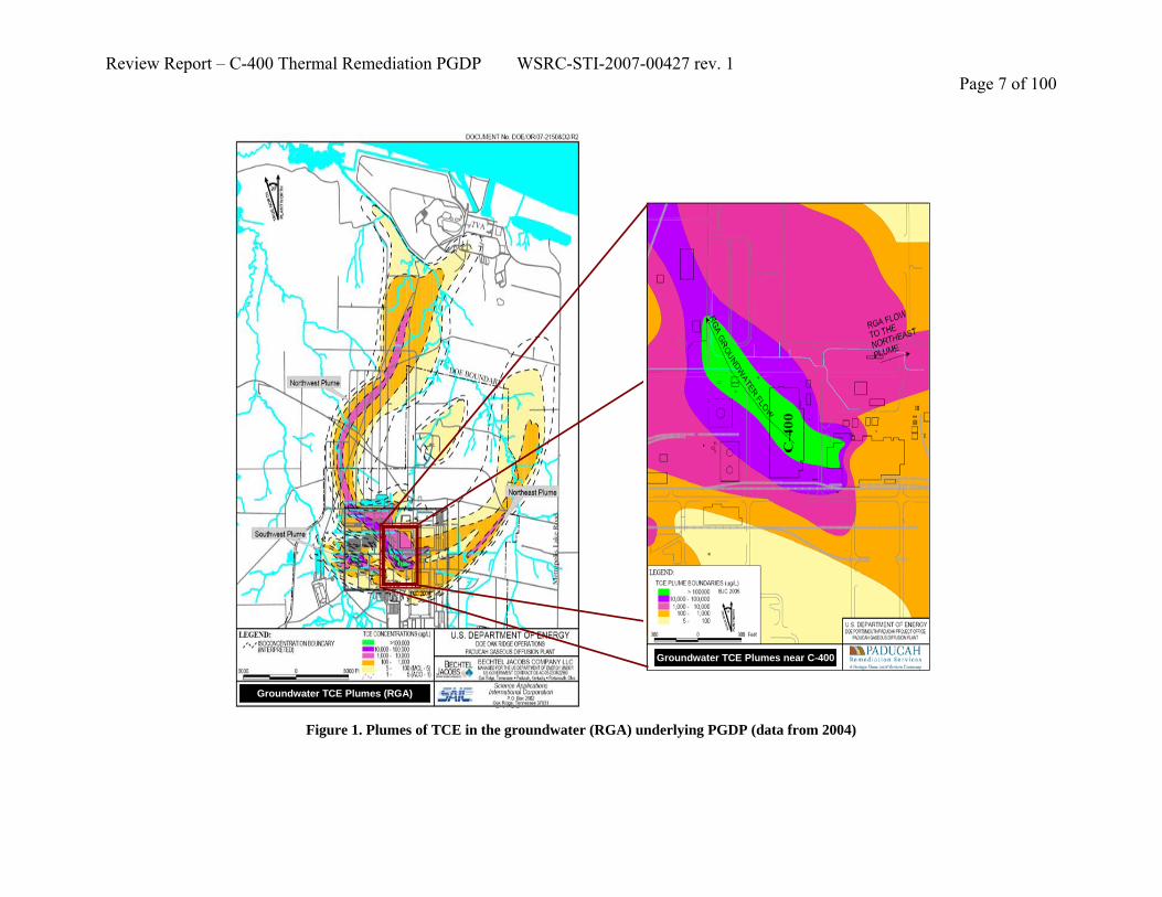
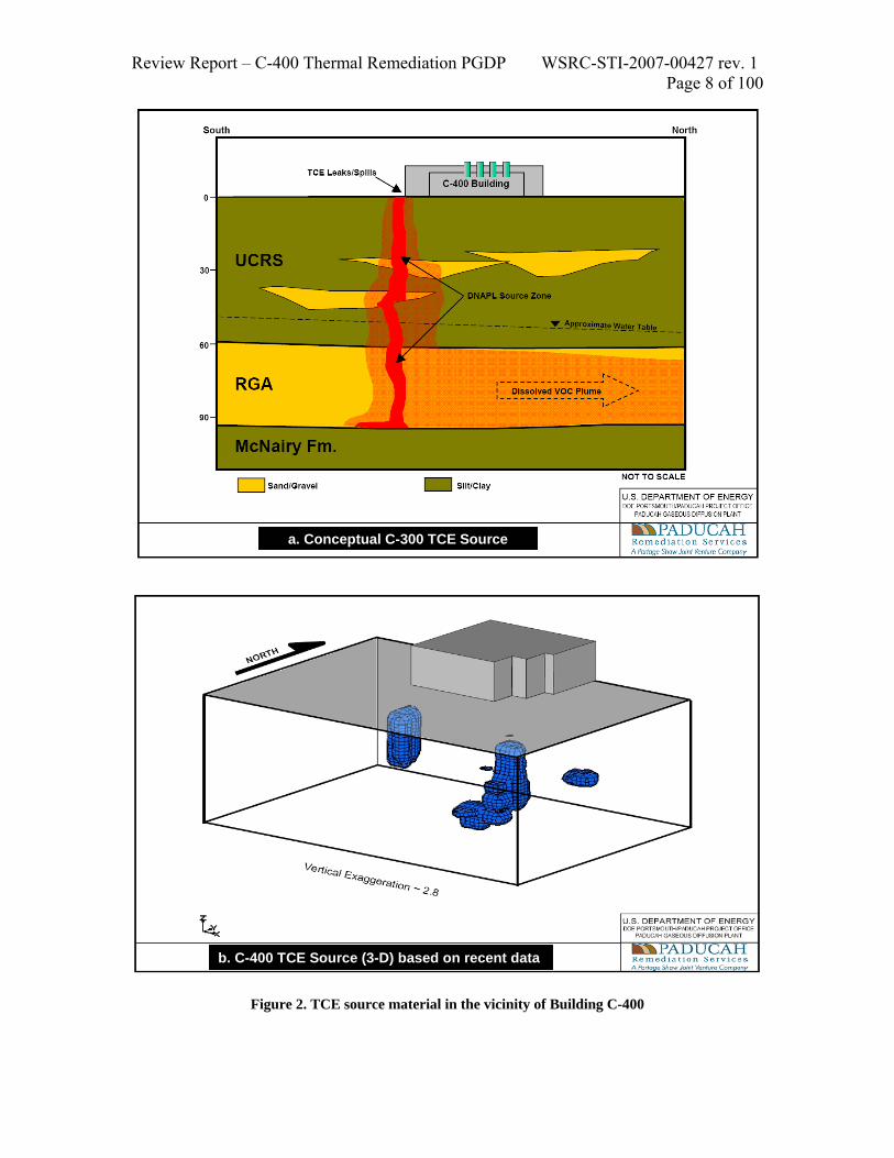
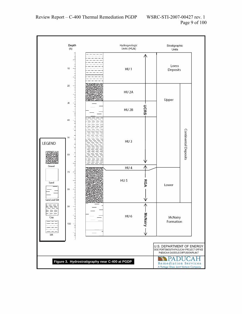
1.0 Background The groundwater underlying PGDP is contaminated by chlorinated solvents, principally trichloroethylene (TCE; Figure 1), as well as other contaminants such as 99Tc. TCE was released as a dense nonaqueous phase liquid (DNAPL) to the subsurface soils and groundwater as a result of operations that began in 1952. As shown in Figures 1 and 2, the Building C-400 area is coincident with the highest TCE concentrations (i.e., the centroid) in the groundwater plumes at PGDP. Based on all characterization data collected to date, DNAPL residing in the Building C-400 locality represents a dominant historical and current source of TCE solvent contributing to the large PGDP groundwater plume(s). Other known and potential sources of TCE exist at PGDP (e.g., various hazardous and radioactive burial grounds and disposal facilities); however active remediation of the DNAPL in the subsurface near Building C-400 (Figure 2a) is a responsible step to minimize the transfer of TCE mass from the source zone into the groundwater plume(s). The subsurface in the vicinity of Building C-400 (Figure 3) has three relevant hydrogeologic zones: 1) the Upper Continental Recharge System (UCRS; about 0-65 feet deep); 2) the Regional Gravel Aquifer (RGA; about 65-87 feet deep); and 3) the underlying McNairy Formation (McNairy; greater than 87 feet deep). These principal zones can be further subdivided based on detailed layering and sediment properties (Figure 3). Groundwater (the “water table”) is at a depth of about 34 feet and occurs within the lower UCRS. Near the C-400 Building, DNAPL has been identified both above and below the water table in the UCRS, in the RGA, and in the upper portion of the McNairy Formation (Figure 2a & b). Following transfer of TCE from the source zone, the dissolved phase plume is transported by groundwater flow primarily in the relatively permeable RGA.
Key Points: The C-400 TCE source zone clean-up is a large commitment that is important to the PGDP cleanup and to DOE. The project is a challenging application of the selected technology (ERH) in a unique and complex setting. To help assure success, DOE commissioned a team of recognized independent experts to perform a Remedy Review
Review Report – C-400 Thermal Remediation PGDP WSRC-STI-2007-00427 rev. 1 Page 7 of 100
Groundwater TCE Plumes (RGA)
Groundwater TCE Plumes near C-400
Figure 1. Plumes of TCE in the groundwater (RGA) underlying PGDP (data from 2004)
Review Report – C-400 Thermal Remediation PGDP WSRC-STI-2007-00427 rev. 1 Page 8 of 100
a. Conceptual C-300 TCE Source
b. C-400 TCE Source (3-D) based on recent data
Figure 2. TCE source material in the vicinity of Building C-400
Review Report – C-400 Thermal Remediation PGDP WSRC-STI-2007-00427 rev. 1 Page 9 of 100
Figure 3. Hydrostratigraphy near C-400 at PGDP

Review Report – C-400 Thermal Remediation PGDP WSRC-STI-2007-00427 rev. 1 Page 10 of 100
The Paducah Remediation Team is working with regulators and stakeholders to address soil and groundwater contamination, and to develop a risk-based end-state goal for the site (DOE, 2005). Interim actions to mitigate known contaminant sources around Building C-400 are an important component of any PGDP-wide efforts and activities such as treatment or removal near known sources such as Building C-400 are a current focus that is being implemented under the Comprehensive Environmental Responsibility Compensation and Liability Act (CERCLA §121). In this case, the activity is being permitted as an Interim Action under CERCLA (§121). According to the Record of Decision (ROD), this interim action has the following remediation goals and expectations:
• It will contribute to the final remediation of the Groundwater OU by removing a significant portion of the contaminant mass of TCE and other VOCs at the C-400 Cleaning Building.
• It will reduce the period of time that TCE concentration in groundwater remains above its Maximum Contaminant Level (MCL), and meets the statutory preference for attaining permanent solutions through treatment.
• It is not expected to meet the MCL in groundwater for TCE, but satisfies the requirements set forth in 40 CFR 300.430(f)(1)(ii) for interim measures that will become part of the total remedial action that will attain applicable requirements (ARARs).
• It will be cost-effective based upon the estimates available at the time of the ROD. • It will permanently remove a significant portion of the TCE near the C-400
Cleaning Building area through treatment, but will result in hazardous substances, pollutants, or contaminants remaining on-site at levels precluding unlimited use and unrestricted exposure.
• It meets CERCLA’s preference for remedies that employ treatment as a principal element of the remedy that permanently and significantly reduces toxicity, mobility, or volume of hazardous substances, pollutants, or contaminants.
Electrical resistive heating (ERH) was the technology specified in the ROD to remove TCE sources from the subsurface sediments near Building C-400. This technology heats the subsurface by applying an electric current between electrodes installed in the target volume. A power source at the surface is connected to the spatially separated (usually 5’ to 20’) electrodes and provides a voltage difference between them. When electric current flows through the subsurface materials between the electrodes, heat is generated from the resistance to current flow. The heat transported through the target volume increases the vapor pressure and therefore the volatility of the TCE. Contaminants volatilized by the heating are captured using soil vapor extraction (SVE) wells along with groundwater/steam extraction wells. In 2003, PGDP performed a small-scale pilot test of ERH and demonstrated that
Key Point: The properties and conditions in various contaminated hydrogeologic layers differ widely at the site. Technologies selected for source reduction near Building C-400 must be carefully designed to address the expected heterogeneity and provide robust performance.

Review Report – C-400 Thermal Remediation PGDP WSRC-STI-2007-00427 rev. 1 Page 11 of 100
significant amounts of TCE mass could be removed from both the UCRS and the RGA near Building C-400. However, the high hydraulic conductivity in some portions of the RGA (i.e., about 425 feet/day) represents a specific technical challenge for ERH, because the inflow of colder, surrounding groundwater may exceed the rate of ERH energy delivery required to adequately heat all portions of the target volume. The pilot test results highlighted this challenge and the need to carefully design ERH for PGDP to make sure all parts of the RGA profile can be heated to target temperatures (especially the RGA-McNairy interface in locations where TCE penetrated to the bottom of the RGA and into the upper portion of the McNairy). 2.0 Remedial Design Review Goals This ITR assessed the proposed remedy for reducing residual solvent sources present in soil and groundwater in the vicinity of Building C-400 at the PGDP. Central to this assessment are the 90% Remedial Design Report (90% RDR); the site characterization and investigation interpretations; as well as supporting documents, technical and financial reports. For the purposes of this report, the review focuses on the 90% RDR and site investigation (RDSI). The primary goal was to assess the technical adequacy of implementing the remedy as specified in these documents to meet the interim remedial action objectives of the ROD. As part of the assessment, the ITR team endeavored to document its findings and recommendations sufficiently for DOE to determine if modifications are warranted pertaining to the design, schedule, or cost of implementing the remedy. 3.0 Remedial Design Review Team and Process 3.1 Review Team Composition The ITR team has extensive experience and knowledge in source term characterization and delineation, thermal treatment remediation, field implementation, safety considerations, and cost estimation. The ITR team is free of conflict-of-interests with Shaw Engineering and Portage Environmental, Inc.
(1) Dr. Brian B. Looney, Savannah River National Laboratory; Environmental Engineer and Review Technical Lead
(2) Dr. Jed Costanza, Georgia Tech, Environmental Engineer and Team Member (3) Dr. Eva Davis, U.S. Environmental Protection Agency (EPA)-R.S. Kerr
Laboratory; Hydrogeologist and Team Member (4) Dr. Joe Rossabi, Redox-Tech, LLC, Soil Scientist and Team Member (5) Dr. Lloyd (Bo) Stewart, Praxis Environmental Technologies; Environmental
Engineer and Team Member (6) Dr. Hans Stroo, HGL, Inc.; Soil Scientist and Team Member

Review Report – C-400 Thermal Remediation PGDP WSRC-STI-2007-00427 rev. 1 Page 12 of 100
Ms. Beth Moore is the DOE Office of Soil and Groundwater Remediation (EM-22) Review Project Manager; Dr. Steve Golian is the EM-22 compliance interface for PGDP. Appendix A provides a short Curriculum Vita for each member of the ITR team. 3.2 Site Visit, Presentations, and Persons Contacted The ITR team convened at PGDP from April 9-12, 2007, to conduct an onsite visit of the thermal treatment area adjacent to Building C-400, review other TCE source areas, and visit downgradient areas affected by the groundwater plumes. Presentations were given by DOE PPPO, PRS, and ERH subcontract staff on April 10, 2007, as detailed below. An outbriefing of initial Remedial Review observations and recommendations from the site visit was presented to DOE PPPO and PRS staff on April 12, 2007, by the Review Technical Lead, Brian B. Looney.
• Dave Dollins, DOE PPPO; Opening Comments • Bryan Clayton, PRS; Ground Water Operating Unit Strategy and C-400
Interim Remedial Action Decision Documents • Ken Davis, PRS; Site Investigation Data, Characterization, and Source
Delineation • Mike Clark, PRS and Brent Winder, McMillan-McGee; C-400 Interim
Remedial Design Action 90% Remedial Design
The following individuals were contacted during the remedial review to obtain their observations and input on the RDSI and numerical modeling design:.
• David Dollins, DOE PPPO • Rich Bonczek, DOE PPPO • Reinhard Knerr, DOE PPPO • Bruce Phillips, Navarro • Ken Davis, PRS • Tracey Brindley, PRS • Chris Richards, PRS • Bruce McGee, McMillan-McGee • Brent Winder, McMillan-McGee • Randall Juhlin, McMillan-McGee • Stuart Shealy, Shaw Engineering • David Cacciatore, Shaw Engineering

Review Report – C-400 Thermal Remediation PGDP WSRC-STI-2007-00427 rev. 1 Page 13 of 100
4.0 Lines of Inquiry The assessment was structured to address the breadth of characterization and design issues in an organized manner using the following lines of inquiry (LOIs) for the remedial review:
1. Site investigation and target zone delineation Review site investigation studies (i.e., borehole data, groundwater samples, Membrane Interface Probe studies, etc.) to ascertain if TCE source zone characterization and delineation in the vadose and saturated zones (i.e., UCRS and RGA units) is sufficient (1) to define the treatment zone(s), and (2) to support the remedial engineering design, including selected technologies to meet the remedial action objectives
2. Performance objectives
Assess the expected performance and effectiveness of the 90% Remedial Design (1) to maximize TCE removal in soil and groundwater, (2) to achieve remediation objectives of the Interim ROD, and (3) to verify that a clear and realistic exit strategy exists for the remedial project. Further, the Review Team will evaluate and/or recommend methods to measure performance of source and groundwater treatment and to help determine remedial effectiveness and contractor performance.
3. Project and design topics
Assess the 90% Remedial Design for (1) adequacy and accuracy of the design basis (e.g., mass balances, flow rates, energy requirements, and anticipated technology performance); (2) implementation strategy; (3) flexibility and contingencies when deviations from the design basis are encountered during installation or operation (e.g., soil permeabilities, depths to the McNairy interface, and DNAPL location); and (4) adequacy of the aboveground treatment system to handle the anticipated influent from the subsurface.
4. Health and safety
Assess the 90% Remedial Design for safety-related issues associated with full-scale thermal treatment implementation. This initial safety assessment will complement, but not replace that required by a formal Operational Readiness Review.

Review Report – C-400 Thermal Remediation PGDP WSRC-STI-2007-00427 rev. 1 Page 14 of 100
5. Cross cutting issues and independent cost evaluation
Determine if costs are reasonable and commensurate with other government remedial projects of similar scope, size, and duration, and if opportunities exist for reductions in cost. Provide input on overarching project-related topics, identify lessons learned from the review effort to date, and provide technical input to support management and contracting success.
5.0 Remedy Review Findings and Recommendations The following sections document the findings and recommendations of the ITR. The sections are organized according to the LOIs presented in Section 4. Each section begins with an introduction followed by an evaluation of specific technical issues. Each issue is identified, a brief evaluation narrative is provided, and the section ends with one or more recommendations. In cases where more detailed evaluation was appropriate to the ITR goals, the section refers to an appendix that provides more detail to assist PPPO and their contractors in addressing and resolving the issues. Many of the recommendations are interrelated and key cross-links are identified to emphasize the need for adequate and comprehensive consideration. 5.1 Site investigation and target zone delineation The volume of subsurface to be heated during thermal treatment is based on the extent of TCE DNAPL. If too small a volume is heated, then there is a risk of mobilizing TCE to areas outside the treatment volume leaving DNAPL within the subsurface. On the other hand, treating a larger volume than necessary means that thermal energy will be directed to subsurface volumes that are free of DNAPL. Thus, adequate characterization of the extent of DNAPL is critical for determining the subsurface volume to be heated. The target source zones as identified for treatment in the 90% RDR (e.g., Figures 11 and 15) address a substantial TCE DNAPL source and are consistent with the ROD. The use of the MIP data along with previous data and conceptual modeling is defensible and generally appropriate to use as the initial basis for ERH design and operation. Nevertheless, substantial issues were identified and uncertainties remain with regard to identifying the extent of DNAPL and the placement of ERH electrodes. To address these issues and uncertainties, the ITR team provided specific recommendations about subsurface volumes where soil and groundwater samples should be collected and analyzed during system installation, and encourages flexibility and responsiveness in the design to adjust the installation as needed. In particular, the flexibility to reasonably expand the thermal treatment volume by installing additional ERH electrodes (both vertically and laterally) should be incorporated into the design. The ITR team also recommends additional characterization beneath the C-400 Building. The ITR team cautions that projected improvements in the groundwater plume(s) resulting from thermal

Review Report – C-400 Thermal Remediation PGDP WSRC-STI-2007-00427 rev. 1 Page 15 of 100
treatment of the C-400 area source will be overestimated if the thermal treatment volume does not encompass all TCE DNAPL within, near and downgradient of the thermal treatment volume. 5.1.1 Issue: A primary basis for identification of the thermal treatment target volume was a membrane interface probe (MIP) photoionization detector (PID) response of 2x10⁶ uV between 20 and 30 feet bgs and 9x10⁶ uV below 60 feet bgs. No calibration was performed to determine MIP PID response to neat TCE, and soil and water samples were not collected to confirm MIP PID findings. More than 84,000 measurements collected during the completion of the 52 MIP boreholes as part of the RDSI. The measurements included determining the electrical conductivity of the soil, temperature of the MIP as it was pushed through the subsurface, and the responses of a photo ionization detector (PID), flame ionization detector (FID), and electron capture detector (ECD) to the gas stream that swept the permeate side of the MIP membrane. Of those 84,000 measurements, PRS used the maximum value in each 5 foot interval (8,597 of the PID values) to map the extent of TCE contamination from which the footprint of the thermal treatment system was determined. The analysis in Appendix B provides a supplemental evaluation of the proposed thermal treatment volume (using additional projections of the extent of TCE DNAPL source based on all MIP measurements). The raw MIP data from each borehole were provided by PRS in Microsoft Excel format which was then imported into GMS v6.0 software for visual comparison with the planned location of ERH heating elements. Specific details of the evaluation (data input and supporting graphics) are provided in Appendix B and the resulting GMS file will be provided to PRS with the goal of assisting in refining the thermal treatment volume. A key type of output from the effort is shown in Figure 4; this is a cross-section of the C-400 southeast source zone region where the color filled contours represent an interpolation of the MIP PID data. The red color represents responses greater than 2x10⁶ uV and the light blue are responses between 1 and 0.5x10⁶ uV. Overlaying the contours are MIP borehole logs where the black line associated with each MIP borehole is the discrete depth ECD responses in uV. Also shown are the proposed locations of ERH electrodes indicated as red columns. Since no confirmation soil or groundwater samples were collected from the MIP boreholes, the PID responses associated with TCE DNAPL are unknown. However, there were two other detectors used to analyze the gas stream collected by the MIP including the FID and ECD. While the FID responses were similar to that of the PID (not shown), there appears to be a relationship between the interpolated PID values to the ECD responses as shown in Figure 4. For example, the PID response from MIP29 between 68 and 76.6 feet bgs (311 and
Key Point: Cross sections of the data collected to support remediation design for TCE DNAPL near the C-400 Building indicate that some expansions of the target volume boundaries, both vertically and laterally, may be needed.

Review Report – C-400 Thermal Remediation PGDP WSRC-STI-2007-00427 rev. 1 Page 16 of 100
302 feet elevation) was greater than 2x10⁶ uV and the ECD detector was at the maximum response of 1.3x10⁷ uV in this region as well. The similarity between the maximum ECD and PID responses that suggested the presence of TCE DNAPL are also evident in the MIP13, MIP16, and MIP24 results. Note that the treatment volume targeted by the electrodes does not extend to the east to encompass the MIP29 location, where PID responses exceeded the 9x10⁶ uV PRS DNAPL threshold value near 75.7 feet bgs.
Figure 4. MIP Boreholes and ECD response overlaying interpolation of PID responses in the
Southeast Source Zone area (looking North).
MIP-10 MIP-13 MIP-16 MIP-24 MIP-29
E59 E60 E61 E62 E72
>2x10⁶
>0.5x10⁶

Review Report – C-400 Thermal Remediation PGDP WSRC-STI-2007-00427 rev. 1 Page 17 of 100
The southern and northern limits of the Southeast thermal treatment zone are worthy of additional examination. Figure 5 shows ECD responses and PID interpolations indicating the possible presence of DNAPL to the south of MIP18. However, since MIP44 only extended to 55 feet bgs, there are insufficient data to support the assumption that MIP18 defined the southern-most limit of neat TCE. North of MIP50, the treatment volume extends to 66.3 feet bgs even though TCE DNAPL may be present at depths down to 104 feet bgs based on the PID interpolations and the ECD response from MIP50.
Figure 5. MIP Boreholes and ECD response overlaying interpolation of PID responses in the
Southeast Source Zone area (looking West).
MIP-44 MIP-18 MIP-17 MIP-16 MIP-50
E34 E39 E54 E70 E78 E81
E85

Review Report – C-400 Thermal Remediation PGDP WSRC-STI-2007-00427 rev. 1 Page 18 of 100
Similarly, in the Southwest source zone area (Figure 6), the thermal treatment volume does not extend to the lower permeability soil found at approximately 100 feet bgs. The PID responses were greater than 0.5x10⁶ uV at 100 feet bgs and the ECD was at the maximum value in MIP04, therefore, TCE source may be present at this depth.
Figure 6. MIP Boreholes and ECD response overlaying interpolation of PID responses in the
Southwest Source Zone area (looking North).
MIP-35 MIP-03 MIP-04 MIP-07
E09
E10 E11E12E19
E20

Review Report – C-400 Thermal Remediation PGDP WSRC-STI-2007-00427 rev. 1 Page 19 of 100
Another area of interest is near 400-046 on the east side of the building, where groundwater concentrations of TCE in excess of 100 mg/L were found during the WAG6 investigation. While the ECD was at its maximum response value in all four MIP boreholes shown in Figure 7, the PID values for MIP19 never exceeded 0.7x10⁶ uV. However, there were two depths for MIP22 where PID readings exceeded 1x10⁶ uV including between 61 and 65, and 77 and 78 feet bgs. This area should be sampled during system installation and treated if necessary.
MIP38 MIP19 MIP22 MIP39
E93
0.5 to 1x10⁶ uV< 0.5x10⁶ uV
Figure 7. MIP Boreholes and ECD response overlaying interpolation of PID responses in the East
Southeast Source Zone area (looking North). Recommendations: 5.1.1 The ITR team determined that the target zone delineation should be modified based on data collected during system installation and based on key data from the 90%RDSI. Subsidiary and cross-linked recommendations are: 5.1.1a, 5.1.1b, 5.3.1, 5.3.4, and 5.3.5. 5.1.1a Collect soil and groundwater samples during the installation of the ERH boreholes with the specific goals of evaluating the MIP dataset and refining the treatment volume. Once the dataset is validated, then the treatment volume can be refined to address areas where TCE DNAPL may be present. This may involve an increase in the lateral and vertical extent of the thermal treatment volume in the Southeast source zone area, and in the potential source zone area to the east. 5.1.1b Increase the vertical extent of the thermal treatment volume in the Southwest source zone area into the low permeability McNairy. Data collection should be integrated into the installation with the contingency to expand both the treatment target

Review Report – C-400 Thermal Remediation PGDP WSRC-STI-2007-00427 rev. 1 Page 20 of 100
zone (e.g., up to 15%) by adding electrodes either below or laterally, and the associated recovery systems. Some boreholes should be extended through the RGA to the McNairy interface in each treatment area. 5.1.2 Issue: There are currently not enough wells to satisfactorily monitor groundwater contamination and contaminant flux zones in the C-400 area. Of particular importance are interfacial zones (e.g., RGA and McNairy) where effective treatment will be challenging. The C-400 area has only a few groundwater monitoring wells with limited screen intervals (Figure 8). Although depth-discrete soil samples and the MIP have been useful for characterizing the source area, monitoring wells as indicators of the overall ground water contamination in the area are usually the ultimate regulatory criteria for cleanup. MW 155 (screened in the lower RGA) and MW156 (screened in the upper RGA) appear to be the only monitoring wells in the principal source area on the southeast side of the C-400 building. Wells MW175 (screened in the middle RGA), MW342 (also screened in the middle RGA), and MW343 (screened in the lower RGA) on the northwest side of the building are downgradient wells from the main source. Because these listed wells are widely spaced and may not have comparable screen zones, their data will have limited utility to adequately evaluate groundwater response in the C-400 source area. Nevertheless, there are interesting historical concentration trends through time for these wells which suggest these types of data may be useful (graphs of these trends are provided in Appendix C). Two of the trends observed include a decrease in TCE concentration from initial monitoring in the upper and middle RGA wells and relatively constant or increasing concentrations in the lower RGA. Three of the monitoring wells (MW343, MW155, and MW156) show a distinct change in concentrations following the ERH pilot test conducted in February through September 2003. TCE concentrations in MW156 (upper RGA) dropped from values greater than 150 mg/l to less than 50 mg/l following the pilot test. TCE concentrations in MW155 (lower RGA) rose from approximately 2 mg/l to 8 mg/l. While TCE concentrations in MW343 (lower RGA, down gradient) moved from an average of approximately 80 mg/l to an average of 70 mg/l. Wells MW175 and MW342 do not seem to be significantly affected by the pilot test.
Key Point: Additional groundwater monitoring wells will be required to determine the impact of thermal treatment on the amount of TCE mass being released to the RGA.

Review Report – C-400 Thermal Remediation PGDP WSRC-STI-2007-00427 rev. 1 Page 21 of 100
C40
0C
400
Figure 8. Monitoring Wells in the vicinity of the C-400 Building at PGDP
Review Report – C-400 Thermal Remediation PGDP WSRC-STI-2007-00427 rev. 1 Page 22 of 100
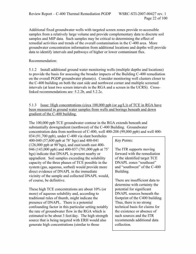
Additional fixed groundwater wells with targeted screen zones provide re-accessible samples from a relatively large volume and provide complementary data to discrete soil samples and MIP data. Such samples may be critical to determining the effect of remedial activities and trends of the overall contamination in the C-400 area. More groundwater concentration information from additional locations and depths will provide data to identify intervals and pathways of higher or lower contaminant flux. Recommendation: 5.1.2 Install additional ground water monitoring wells (multiple depths and locations) to provide the basis for assessing the broader impacts of the Building C-400 remediation on the overall PGDP groundwater plume(s). Consider monitoring well clusters closer to the C-400 building on both the east side and northwest corner and multiple screened intervals (at least two screen intervals in the RGA and a screen in the UCRS). Cross-linked recommendations are: 5.2.2b, and 5.2.2c. 5.1.3 Issue: High concentrations (circa 100,000 ppb (or µg/L)) of TCE in RGA have been measured in ground water samples from wells and borings beneath and down gradient of the C-400 building. The 100,000 ppb TCE groundwater contour in the RGA extends beneath and substantially downgradient (northwest) of the C-400 Building. Groundwater concentration data from northwest of C-400, well 400-208 (99,000 ppb) and well 400-034 (91,700 ppb), under C-400 via slant boreholes 400-040 (57,600 ppb at 78’ bgs) and 400-041 (126,000 ppb at 90’bgs), and east/south east 400-046 (143,000 ppb) and 400-037 (701,000 ppb at 75’ bgs) indicate that DNAPL is present nearby or upgradient. Soil samples exceeding the solubility capacity of the three phases of TCE possible in the system (gas, aqueous, sorbed) would provide more direct evidence of DNAPL in the immediate vicinity of the sample and collected DNAPL would, of course, be definitive. These high TCE concentrations are about 10% (or more) of aqueous solubility and, according to traditional rules of thumb, might indicate the presence of DNAPL. There is a potential confounding factor in this particular setting notably the rate of groundwater flow in the RGA which is estimated to be about 3 feet/day. The high strength source that is being targeted with ERH would also generate high concentrations (similar to those
Key Points: The ITR supports moving forward with the remediation of the identified target TCE DNAPL zones “southeast” and “southwest” of the C-400 Building. There are insufficient data to determine with certainty the potential for significant DNAPL sources beneath the footprint of the C400 building. Thus, there is no strong technical basis for claims for the existence or absence of such sources and the ITR recommends additional data collection.

Review Report – C-400 Thermal Remediation PGDP WSRC-STI-2007-00427 rev. 1 Page 23 of 100
observed), and because of the RGA groundwater flow combined with minimal TCE degradation, could result in the observed dissolved phase plume migration and contaminant configuration. In extremely large source release cases such as PGDP, the traditional rules of thumb may be misleading. In this instance, 100,000 ppb TCE is likely indicating DNAPL, but it might be 1) upgradient some distance (i.e., the identified source that is already being targeted), or 2) it might extend beneath and/or downgradient of the C-400 building. The MIP data are consistent with former interpretation but are not definitive. The ITR team can not discount the potential for significant DNAPL under C-400, however, the consensus of the independent evaluation is that the targeted TCE DNAPL volume (if the zone is modified as recommended in 5.1.1) represents a substantial source, is generally consistent with the ROD objectives, and is a defensible basis for a thermal treatment. As noted above, TCE DNAPL that remains in the subsurface at PGDP following the thermal treatment will reduce the effectiveness of the remediation as measured by future improvements in downgradient plume concentrations. Therefore, additional characterization and (if needed), appropriate response activities in coordination with C-400 building activities would be prudent. Recommendation: 5.1.3: Additional characterization beneath and to the north of the C-400 Building is needed to determine if the high concentrations that have been measured are due to the “known” upgradient sources or if substantive TCE DNAPL is beneath the footprint of the building. If substantive TCE DNAPL is identified beneath the building, then additional response actions to remove source may be needed to further mitigate contaminant mass transferred to the groundwater plume(s). Characterization and response actions will require coordination with Building C-400 activities and the ITR team recognizes that it may be necessary to conduct this characterization at a future time. Cross-linked recommendations are: 5.2.2b, and 5.2.2c. 5.1.4 Issue: Limited data were provided in the RDSI related to potential co-contaminants. The primary contaminants in the vicinity of the C-400 Building are the TCE DNAPL and 99Tc. Thus, these contaminants form the basis of most of the data collection and subsequent design. It is important to note that the TCE DNAPL is a separate organic phase that concentrates and serves as a vector for the migration of any hydrophobic compounds that were either co-disposed with (or used near) the original TCE solvent. The TCE DNAPL will also contain hydrophobic compounds that are present in the subsurface migration path. The presence of co-contaminants is common at DNAPL sites with typical co-contaminants including anthropogenic polychlorinated biphenyls, solvent preservatives, and naturally occurring radon from the subsurface. These co-contaminant compounds are typically present at trace concentrations and, except in unusual circumstances, they pose a significantly lower risk than the principle TCE DNAPL. Thus, the ITR team supports the general goal of mass reduction of the TCE DNAPL and the design and operation of the remediation system based on this central goal. Nonetheless,

Review Report – C-400 Thermal Remediation PGDP WSRC-STI-2007-00427 rev. 1 Page 24 of 100
it is prudent to survey for the presence and concentrations of co-contaminants and develop a conceptualization of how they might respond to the remediation. At some sites (e.g., the DOE Savannah River Site and others) observation of measurable levels of co-contaminants has been related to heating and the progress of DNAPL removal. Recommendation: 5.1.4 PGDP should assess the potential for co-contaminants by reviewing process records and analytical results and, if necessary, develop a conceptual model for their behavior during heating. The ITR team supports basing the remediation system design and operation, as well as the waste handling, primarily on the TCE DNAPL and the mass reduction. Cross-linked recommendations are: 5.4.1, 5.4.2 and 5.5.1. 5.2 Performance objectives Electrical Resistive Heating was specified in the ROD as an Interim Remedy to permanently and significantly reduce the mass of contaminants in the C-400 Building area source zone. The ROD states that “Operation of the Electrical Resistance Heating array would cease when the monitoring system indicates that heating has stabilized in the subsurface and the contaminant recovery diminishes to a point where significant additional decreases in this rate of recovery are not anticipated (i.e., the rate of removal of TCE and other VOCs becomes asymptotic).” The 90% RDR further specifies that heating stabilization in the subsurface consists of temperatures in the vadose zone that are above the boiling point of TCE and temperatures below the water table that are above the boiling point of a TCE DNAPL/water combination at the treatment depth, which is expected to be 98oC at 100 ft below ground surface. The 90% RDR also defines asymptotic recovery in the vapor phase as TCE concentrations below 400 ppmv in the extracted vapor for 80% of the analyses from individual vapor extraction wells over a designated four week period in the target treatment zone. During the four week evaluation period samples are collected twice weekly from the vapor extraction wells and analyzed with a photoacoustic field gas monitor. In the sections below, the ITR team provides performance monitoring recommendations. In particular, the ITR team recommends developing technically based performance criteria that are consistent with the ROD objectives (source TCE DNAPL mass removal) and that support efficient operation. Factors such as achieving long-term plume objectives and cleanup exit strategy, and engineering considerations such as cost per unit contaminant removal should be incorporated into the performance metrics.
Review Report – C-400 Thermal Remediation PGDP WSRC-STI-2007-00427 rev. 1 Page 25 of 100
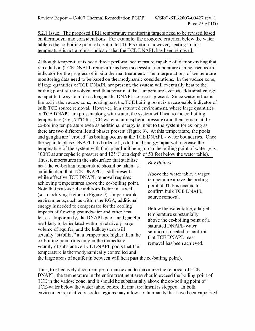
5.2.1 Issue: The proposed ERH temperature monitoring targets need to be revised based on thermodynamic considerations. For example, the proposed criterion below the water table is the co-boiling point of a saturated TCE solution, however, heating to this temperature is not a robust indicator that the TCE DNAPL has been removed. Although temperature is not a direct performance measure capable of demonstrating that remediation (TCE DNAPL removal) has been successful, temperature can be used as an indicator for the progress of in situ thermal treatment. The interpretations of temperature monitoring data need to be based on thermodynamic considerations. In the vadose zone, if large quantities of TCE DNAPL are present, the system will eventually heat to the boiling point of the solvent and then remain at that temperature even as additional energy is input to the system for as long as the DNAPL source is present. Since water influx is limited in the vadose zone, heating past the TCE boiling point is a reasonable indicator of bulk TCE source removal. However, in a saturated environment, where large quantities of TCE DNAPL are present along with water, the system will heat to the co-boiling temperature (e.g., 74oC for TCE-water at atmospheric pressure) and then remain at the co-boiling temperature even as additional energy is input to the system for as long as there are two different liquid phases present (Figure 9). At this temperature, the pools and ganglia are “eroded” as boiling occurs at the TCE DNAPL - water boundaries. Once the separate phase DNAPL has boiled off, additional energy input will increase the temperature of the system with the upper limit being up to the boiling point of water (e.g., 100oC at atmospheric pressure and 125oC at a depth of 50 feet below the water table). Thus, temperatures in the subsurface that stabilize near the co-boiling temperature should be taken as an indication that TCE DNAPL is still present; while effective TCE DNAPL removal requires achieving temperatures above the co-boiling point. Note that real-world conditions factor in as well (see modifying factors in Figure 9). In permeable environments, such as within the RGA, additional energy is needed to compensate for the cooling impacts of flowing groundwater and other heat losses. Importantly, the DNAPL pools and ganglia are likely to be isolated within a relatively large volume of aquifer, and the bulk system will actually “stabilize” at a temperature higher than the co-boiling point (it is only in the immediate vicinity of substantive TCE DNAPL pools that the temperature is thermodynamically controlled and the large areas of aquifer in between will heat past the co-boiling point). Thus, to effectively document performance and to maximize the removal of TCE DNAPL, the temperature in the entire treatment area should exceed the boiling point of TCE in the vadose zone, and it should be substantially above the co-boiling point of TCE-water below the water table, before thermal treatment is stopped. In both environments, relatively cooler regions may allow contaminants that have been vaporized
Key Points: Above the water table, a target temperature above the boiling point of TCE is needed to confirm bulk TCE DNAPL source removal. Below the water table, a target temperature substantially above the co-boiling point of a saturated DNAPL-water solution is needed to confirm that TCE DNAPL mass removal has been achieved.
Review Report – C-400 Thermal Remediation PGDP WSRC-STI-2007-00427 rev. 1 Page 26 of 100
from other areas to recondense, and heating of the entire target zone to these temperature targets is the most robust thermal performance measure that supports achieving the ROD objectives. However, from a practical standpoint, the heating may not be perfectly uniform. Temperatures close to the electrodes will approach the boiling point of water and temperatures will vary as a function of distance from the electrodes, depth, extraction well operation, inflow of water from the boundaries and other factors. Site specific design modeling (see section 5.3) should be used to support the development of reasonable performance metrics for temperature, and the ITR team supports setting the temperature targets as close to the boiling point of water as is achievable. At other sites where ERH remediation has been used, the temperature criteria specified that a certain percentage of temperature monitoring points (one temperature monitoring point per unit volume) reach the temperature criteria. With automated temperature measurement systems, temperatures are measured frequently during the day and then reported on an average daily basis. A key to setting up this type of approach is to make sure that there is no pattern in the temperature distribution which would indicate that a key area of known TCE DNAPL is not being effectively heated (e.g., the lower portion of the RGA in areas where TCE DNAPL has penetrated to the McNairy). Recommendation: 5.2.1 The temperature target above the water table should be based on exceeding the boiling point of the TCE DNAPL. The temperature target below the water table should be set between the co-boiling point of a TCE-water mixture and the boiling point of water (at the nominal local pressure conditions). The final target temperatures should be based on site-specific modeling. Throughout the saturated target zone, the target temperature should be set as close to the boiling point of water as is realistic and achievable, and the temperature monitoring system should be set up to sample in a representative manner and to assure that all areas of known DNAPL are effectively heated. Cross-linked recommendations are: 5.2.2, 5.2.3, 5.2.5, 5.3.3, and 5.3.7.

Review Report – C-400 Thermal Remediation PGDP WSRC-STI-2007-00427 rev. 1 Page 27 of 100
Tem
pera
ture
ambient
solvent-waterco-boiling
point
water boilingpoint
Operational Condition and Source Response
heating initiated
activesolventpool
‘erosion’
solventphase
removed
waterinflow and heat
losses
discreet-isolatedsolventpools within
a large aquifer
Simplified Impacts of “real-world” conditions
Figure 9. Idealized heating profile for a simple saturated system containing TCE DNAPL and water 5.2.2 Issue: The stopping point criteria of an asymptote of less than 400 ppmv in the soil gas and co-boiling point temperature are not necessary and sufficient conditions for ERH remediation shut down. The current criteria for terminating the ERH remedial action are heat stabilization at specified temperatures and “asymptosis” of the supporting soil vapor extraction system below a TCE concentration of 400 ppmv (2186 mg/m3 at STP) for four weeks. ERH operations of electrode heating and soil vapor extraction are coupled, implying that these generally separate components are either on or off together. Although the ITR team agrees with the idea of treating to a point of “diminishing returns” in terms of concentrations in the extracted vapors, this criteria alone is not appropriate for ERH termination because it may allow system shut down when additional contaminant mass removal is still cost effective and warranted or it may prevent shut down when additional contaminant mass removal is not economical and not significantly protective of human health or the environment. The Paducah site wide remedial goals and the costs of additional remedial activities to reach these goals would determine this. An example of how the criteria would force a premature end to treating the site is when the mass of TCE being removed is still substantial, even though the asymptotic goal has been reached. For instance, if SVE is operating at 1000 scfm (28.3 m3/min) and

Review Report – C-400 Thermal Remediation PGDP WSRC-STI-2007-00427 rev. 1 Page 28 of 100
concentrations are 400 ppmv (2.2 g/m3), daily removal of TCE is approximately 197 lbs (89.4 kg) or 16 gallons (61 L) of neat TCE per day. Depending on the daily cost of operation of the ERH system at that time, which may be very small if electrodes are turned off and only SVE is running and heating operations decoupled, continued operation is likely to be warranted and cost effective. An example where the criteria prevents cost effective shut down occurs when the mass of TCE being removed has reached an asymptote that is higher than 400 ppmv. This scenario could occur if a significant amount of contaminant mass is retained in fine grain materials within the shallow sediments (0-20 feet depth) that are located above the heating zone. If the heating and SVE operations are not decoupled, unnecessary cost and energy would be expended heating the already cleaned zone (i.e, greater than 20 feet depth) with little effect on relevant contaminant removal, particularly if the SVE flow rates are low. Effluent vapor concentrations should be measured frequently during remediation to determine the amount of contaminants being recovered and to look for declining rates of recovery, which may indicate that the remediation is approaching diminishing returns. However, without a supporting theoretical analysis, an arbitrary concentration in the vapor phase (e.g., 400 ppmv) is not a direct measure of achieving removal of TCE DNAPL, which is the goal stated in the ROD. Vapor phase concentrations can be affected by vapor flow rates, boundary conditions, and where the measurements are being made. Thus, calculation of recovery rate in terms of mass per day is a more direct measure of what is being accomplished by the remediation system. At what time diminishing returns has truly been achieved and when it is most cost effective (in terms of the overall strategy for clean up of the entire site) to discontinue heating is a decision that must be made for each separate target zone while keeping in mind the goal of the remedial action (source zone mass reduction) and the overarching goals of the groundwater remediation as a whole (reduction in mass flux entering the downgradient plumes). Consideration should also be given to the cost of recovery of the same amount of contaminants using alternative technologies (e.g., pump and treat in terms of the volume of water that would have to be extracted and treated and the associated costs) Contaminant concentrations and recovery rates in the effluent vapors should be expected to vary considerably over time during the remediation, and different sites will show different trends depending in part on where the contaminants are located in the subsurface. For example, if most of the contamination is near the water table and relatively accessible to the SVE system, then most of the mass recovery may be early on during the remediation. For a site where there is considerable contamination at depth below the water table, the recovery rate may be low until the co-boiling temperature is met and/or exceeded within the areas where the
Key Point: Technically based metrics are needed to support shut down and an integrated-diverse set of metrics should be developed to support an overall implementation that minimizes costs and maximizes effectiveness in the different parts of the subsurface.

Review Report – C-400 Thermal Remediation PGDP WSRC-STI-2007-00427 rev. 1 Page 29 of 100
contamination exists. At this site, it appears that considerable contamination may exist both in the vadose zone and at depth below the water table in some areas. Thus, the temperature criteria at the depths where the contamination is expected to exist should be met before any consideration is given to whether or not vapor concentrations are past the peak and have declined to the point of diminishing returns. It should also be noted that the basis of the current proposed vapor phase performance metric (400 ppmv) was the data collected during the PGDP pilot scale ERH operation. As noted above, the concentration extracted by SVE varies as a result of many factors and (flow rates, boundary conditions, well locations, etc.) and the earlier data are not an adequate basis for setting a primary measure of success for the full scale remediation of the C-400 area TCE DNAPL source. Also, although the termination criteria for the ERH pilot scale operation was 100 ppmv and at this extraction rate the concentration reductions goals were met, significant soil and groundwater contamination remained within the area after the termination of the system. Recommendations: 5.2.2 The operational monitoring and stopping criteria for this project should be technically based and developed to assure that performance objectives are met and that the system is operated efficiently. Subsidiary and cross-linked recommendations are: 5.2.2a through 5.2.2c, 5.2.1, 5.2.3, 5.2.5, and 5.3.7. 5.2.2a Do not tie the shut down criteria to any particular vapor phase concentration (rather develop an integrated approach as described in 5.2.3b and 5.2.3c). 5.2.2b The method for determining asymptosis and establishing compliance with the ROD should be negotiated with the regulators after considering, analyzing and weighing a number of technical factors. Asymptosis should be defined and documented for the various collected phases and set to a low mass removal compared to the original mass in the source. Some of the recommended technical considerations include: use mass removal (not concentration) as the basis for asymptosis, a cost of removal comparison (i.e., $/lb for continued operation ERH/SVE versus $/lb for P&T or cut off wall, or another potential future remedial action), mass of TCE remaining in the C-400 source area compared with the mass already in the plume or from other sources, or mass release rate from residual source balanced against separately measured attenuation rates within the downgradient plume. 5.2.2c Identify and use site wide remedial goals to permit bounding calculations and to provide a context for C-400 specific stopping criteria.

Review Report – C-400 Thermal Remediation PGDP WSRC-STI-2007-00427 rev. 1 Page 30 of 100
5.2.3 Issue: The current performance metrics are based primarily on temperature and concentration in gas vapors collected from the site. While the design allows for performance decisions to be made separately for the major treatment cells (e.g., southwest and southeast), it does not adequately consider the needs to decouple the monitoring and decisionmaking for different hydrogeologic targets (e.g., UCRS and RGA) nor does it recognize the value of separate decision processes for turning off heat versus turning off extraction. (note that the operational/equipment aspects of this issue are discussed in more detail under project and design topics) After heating the subsurface to meet the thermal performance objectives, mass removal objectives for various areas and horizons of the site should be implemented. In particular, extraction should not cease while the site continues to hold significant energy. The residual energy in the heated soil can contribute to additional mass removal if the groundwater extraction and vapor extraction operations continue to a point of diminishing returns for source reduction. In the groundwater, concentrations would be expected to increase (and exhibit “spiky” behavior) during heating and as the TCE DNAPL pools are boiled and removed. In this particular environment, groundwater concentration and concentrations trends/behaviors, in combination with temperature are useful to assess the ROD objective. Because the ROD objective is to reduce the contaminant mass in the subsurface, groundwater concentrations should not be expected to reach MCLs before treatment is terminated. However, groundwater concentrations within the treatment area should be reduced below the concentrations that would indicate local TCE DNAPL. Thus, after the temperature goals are achieved, decreasing concentrations, reduced temporal variability, and consistent concentrations below TCE DNAPL indicator levels would be strong evidence that the ROD objectives are met. Recommendations: 5.2.3 Individual termination criteria should be developed for key target zones in the UCRS and RGA and applied to operations in each of the three treatment areas. Subsidiary and cross-linked recommendations are: 5.2.3a, 5.2.3b, 5.2.1, 5.2.2, 5.2.5, 5.3.1, and 5.3.7. 5.2.3a Performance metrics should include groundwater concentrations and groundwater concentration trends/behaviors within the treatment area to indicate the extent of treatment that has been achieved and to aid in determining when the system should be shut down. 5.2.3b The performance criteria for the ERH, the SVE and the water extraction should be decoupled (and necessary monitoring added to the system). Continued operation of the SVE system in the vadose zone should be considered even after the site cools if a cost-effective mass removal rate is achieved.
Review Report – C-400 Thermal Remediation PGDP WSRC-STI-2007-00427 rev. 1 Page 31 of 100
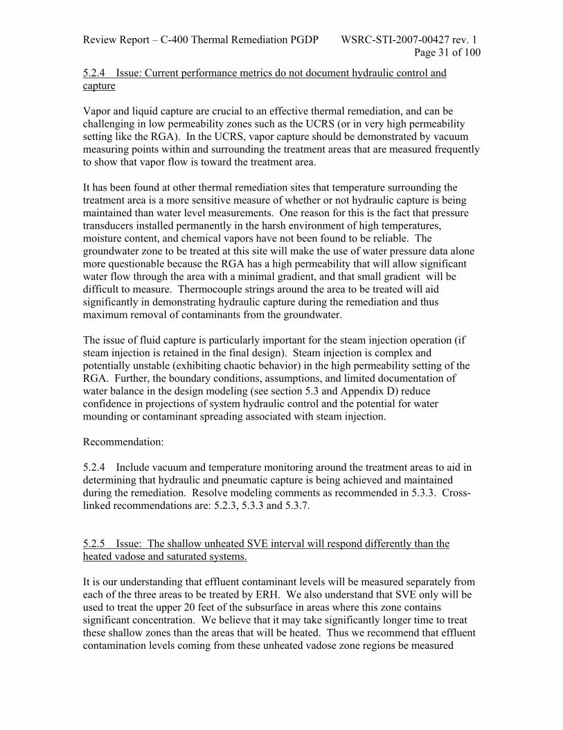
5.2.4 Issue: Current performance metrics do not document hydraulic control and capture Vapor and liquid capture are crucial to an effective thermal remediation, and can be challenging in low permeability zones such as the UCRS (or in very high permeability setting like the RGA). In the UCRS, vapor capture should be demonstrated by vacuum measuring points within and surrounding the treatment areas that are measured frequently to show that vapor flow is toward the treatment area. It has been found at other thermal remediation sites that temperature surrounding the treatment area is a more sensitive measure of whether or not hydraulic capture is being maintained than water level measurements. One reason for this is the fact that pressure transducers installed permanently in the harsh environment of high temperatures, moisture content, and chemical vapors have not been found to be reliable. The groundwater zone to be treated at this site will make the use of water pressure data alone more questionable because the RGA has a high permeability that will allow significant water flow through the area with a minimal gradient, and that small gradient will be difficult to measure. Thermocouple strings around the area to be treated will aid significantly in demonstrating hydraulic capture during the remediation and thus maximum removal of contaminants from the groundwater. The issue of fluid capture is particularly important for the steam injection operation (if steam injection is retained in the final design). Steam injection is complex and potentially unstable (exhibiting chaotic behavior) in the high permeability setting of the RGA. Further, the boundary conditions, assumptions, and limited documentation of water balance in the design modeling (see section 5.3 and Appendix D) reduce confidence in projections of system hydraulic control and the potential for water mounding or contaminant spreading associated with steam injection. Recommendation: 5.2.4 Include vacuum and temperature monitoring around the treatment areas to aid in determining that hydraulic and pneumatic capture is being achieved and maintained during the remediation. Resolve modeling comments as recommended in 5.3.3. Cross-linked recommendations are: 5.2.3, 5.3.3 and 5.3.7. 5.2.5 Issue: The shallow unheated SVE interval will respond differently than the heated vadose and saturated systems. It is our understanding that effluent contaminant levels will be measured separately from each of the three areas to be treated by ERH. We also understand that SVE only will be used to treat the upper 20 feet of the subsurface in areas where this zone contains significant concentration. We believe that it may take significantly longer time to treat these shallow zones than the areas that will be heated. Thus we recommend that effluent contamination levels coming from these unheated vadose zone regions be measured

Review Report – C-400 Thermal Remediation PGDP WSRC-STI-2007-00427 rev. 1 Page 32 of 100
separately from the heated zones, just as the concentrations are being measured separately coming from the various treatment areas. Recommendation 5.2.5 Measure effluent contaminant levels coming from the near surface areas that are being treated by SVE only separately from effluent vapors coming from the heated zone. Cross-linked recommendations are: 5.2.1, 5.2.2, and 5.2.3. 5.3 Project and design topics The proposed implementation of ERH at PGDP is large and complex. The system is designed to treat both vadose and saturated settings and to treat layers that have grossly different hydraulic and electrical properties. The ITR team believes that these challenges necessitate application in a manner that is: 1) responsive and flexible to field conditions, 2) performed with equipment that has a sufficient range to implement contingencies, and 3) based on carefully conceived design models that assist in implementing a robust design. Further, the ITR team recommends a phased approach to implementation (or an alternative approach that mitigates potential project risk) and staged start up and shut down sequences that are based on technical and logistical considerations. 5.3.1 Issue: There is a risk in going “full scale” with the installation because of the size and complexity of this site. Uncertainties remain, particularly in the ability to heat all portions of the RGA including the deepest interval in the Southeast target zone and in linking the heating to the amount/effectiveness of contaminant removal. The ERH pilot test performed at this site, for example, did not fully heat the entire thickness of the RGA and the deepest portions of the section were the most difficult to heat efficiently. While reasonable and prudent steps were implemented in the 90% RDR to address lessons learned from the pilot test, the primary uncertainty is unresolved. The question remains: will the full scale application of ERH in the highly permeable RGA provide adequate energy to reach the desired temperatures? One under-considered factor related to the difficulty in heating the deepest interval of the RGA is large scale convection (Figure 10). Note that this process would tend to pull cooler water into the treatment zone at the bottom and discharge warm water from the upper part of the treatment zone (with some internal cycling occurring within the zone). This particular process is sensitive to boundary conditions in design modeling and the impacts might be exacerbated by the presence of heterogeneities (e.g., a high permeability layer near the top of the RGA).
Key Point: Uncertainty remains and reasonable actions, such as phasing of implementation activities, or procedures and processes that enable operational responsiveness and flexibility, are prudent to mitigate the project risk to DOE.

Review Report – C-400 Thermal Remediation PGDP WSRC-STI-2007-00427 rev. 1 Page 33 of 100
In response to the remaining uncertainties at this site, an earlier technical review team recommended a phased implementation. For example, a phased approach to confirm the ability to heat the RGA to the McNairy interface may include installing a limited number of electrodes in the RGA and performing a test to demonstrate that temperatures can be achieved. A careful examination of the significant number of ERH projects that have been completed since the earlier technical team review (including progress in design modeling) may provide a framework for an appropriate phased implementation for this project despite the lack of implementations in settings as permeable and complex as the C-400 Building area. Recommendation: 5.3.1 The risk of full scale implementation should be mitigated by phasing or by assuring acceptable operational responsiveness and flexibility. Cross-linked recommendations are: 5.2.3, 5.3.1, 5.3.5, and 5.3.9.
cooler water cooler water
warmer waterwarmer water
groundwaterflow
upgr
adie
nt
dow
ngra
dien
t
Regional Gravel Aquifer (RGA)
UCRS
ERHsystem
?
McNairy Figure 10. Simplified schematic of convection processes during ERH of the permeable portion of the
treatment zone

Review Report – C-400 Thermal Remediation PGDP WSRC-STI-2007-00427 rev. 1 Page 34 of 100
5.3.2 Issue: A separate unit operation, steam stripping, is proposed for the ERH pilot test cell area. The need for this technology is based on the potential of electrically-conductive steel shot left over from the earlier pilot-scale demonstration to impact the performance of the full-scale ERH system. The 90% RDR includes the use of a steam injection cell to re-treat the area of the site previously host to the ERH pilot test. Although the goals for contaminant concentration reductions were met, considerable contamination remained in this area at the completion of the pilot test. In addition, it was assumed the area had been re-contaminated by the influx of surrounding TCE DNAPL in the deeper portion of the RGA near the McNairy interface. The shape of the steam front resulting from injection of steam into the RGA at the design rate of about 2,000 pounds per hour was estimated utilizing the model of van Lookeren (1983). The result of the calculation is illustrated in Figure 11. The steam zone exists around the injection well only above the red line and liquids exist below. This plot suggests that the bottom of the RGA will not be significantly heated by steam injection. Any DNAPL in this region will not be displaced and recovered. Further, attempts to mitigate this effect by screening deep in the RGA would not be successful as buoyancy and the path of least resistance would bring the steam zone to the top of the RGA before lateral growth could be achieved deep in the RGA. The re-contamination of the former ERH pilot test area has not been verified by field data to adequately justify the need to re-treat this soil volume with an additional technology. Further, the ITR team believes that the majority of the “shot” emplaced in boreholes for the pilot electrodes would have remained in the boreholes and thus is amenable to removal by overdrilling. This suggests that ERH coverage might be cost effectively added to the primary ERH system if treatment is needed for this area. Recommendations: 5.3.2 The separate steam injection in the area of the ERH treatability study site should be eliminated from design. Subsidiary recommendations are: 5.3.2a and 5.2.2b. 5.3.2a If the steam injection is eliminated the ITR team believes that the remediation objective for that target area could be achieved using the primary ERH system (through expansion of the electrode grid and removal of the former electrodes by overdrilling if necessary). 5.3.2b If the steam injection well remains in the system, extraction wells for hydraulic and pneumatic control must be included around the entire injection well to avoid a redistribution of contaminants to outside of the treatment area.

Review Report – C-400 Thermal Remediation PGDP WSRC-STI-2007-00427 rev. 1 Page 35 of 100
02468
101214161820
0 10 20 30 40Radius (feet)
Ste
am Z
one
Thic
knes
s (fe
et) Steam Zone
Condensate &Groundwater
Lower UCRS Acts as Confining Layer02468
101214161820
0 10 20 30 40Radius (feet)
Ste
am Z
one
Thic
knes
s (fe
et) Steam Zone
Condensate &Groundwater
Lower UCRS Acts as Confining Layer
Figure 11. Estimated Shape of the Steam Injection Front in the RGA 5.3.3 Issue: The potential for success relies on design models that are accurate, site specific, and robust. There has been limited use of such models in high permeability and heterogeneous conditions similar to PGDP – this increases the importance of reducing modeling uncertainties by maximizing the use of available data and by running alternative and bounding cases. A number of simplifications and potentially problematic assumptions were identified in the use of TETRAD to simulate the application of ERH at the site. These include, but are not limited to:
• Hydraulic conductivity values used in portions of the original simulation were one order-of-magnitude higher than values provided by the site geologist. Further, the hydraulic conductivity provided by the site geologist for the RGA (circa 425 ft/day) is below the documented average values reported for the RGA. Further, no design modeling cases included major heterogeneities within the RGA (e.g., high permeability layers near the top and/or bottom of the formation). What are the anticipated impacts of such features
Key Point: The ITR recommends additional design modeling to reduce uncertainty and improve the basis for the ERH design. The team provides specific suggestions to assist in the modeling. The RDSI projections that heating in the deep RGA at the McNairy interface will meet the design goals are not fully substantiated by the current modeling.

Review Report – C-400 Thermal Remediation PGDP WSRC-STI-2007-00427 rev. 1 Page 36 of 100
on the potential for meeting metrics of success and in determining the spacing of electrodes?
• Lateral saturated zone boundaries were assumed to have a specified flux supplemented by a specified head. This hybrid boundary is unusual and is potentially problematic (i.e., masking potential modeling deficiencies and reducing the ability to calibrate and assure that model parameters such as hydraulic conductivities and the range of hydraulic conductivities are correct).
• Contaminant recovery rates and total masses calculated in the simulation were not based on any site-specific data or conceptual site model.
• A specified flow of air across the lateral boundaries of the vadose zone is forced to match the extraction rate of air (i.e., no recharge from the overlying surface).
• The soil electrical properties (e.g., resisitivities) used in the model were based on a limited number of lab measurements and the modeling might be improved if the detailed field data collected during the RDSI were incorporated.
Selected examples are summarized below to clarify the ITR modeling comments and a more detailed modeling discussion is provided in Appendix D. Hydraulic Conductivity: The WAG 6 RI documented that measurements of the hydraulic conductivity of the RGA range from 0.0005 ft/day to 27,000 ft/day with the average value between 2800 ft/day and 5700 ft/day. The ITR team recognizes that hydraulic conductivity measurements for this type of aquifer often range over many orders of magnitude and that that averages can be biased by the extremes of the range. Thus, an estimate by the site geologist of 425 ft/day for the baseline case in the initial design modeling is plausible. Note that a hydraulic conductivity of 425 ft/day is below the “average” hydraulic conductivity reported by relevant site characterization documents and, thus, may not represent a defensible upper bound without additional documentation. With the information currently available, the ITR team recommends setting an upper bounding value of hydraulic conductivity for the design to a value near the average reported in the WAG 6 RI unless there is a clear counterbalancing technical basis or justification. The original design modeling presented to the ITR team included runs for a portion of the modeling that used a hydraulic conductivity approximately 10x higher than the baseline – this already completed case if carried through the various modeling steps may be a reasonable bounding calculation. Further, the potential significance of large-scale heterogeneity (e.g., layering) impacting the design is not explored in the original design modeling. The design uncertainties would be reduced significantly if a reasonable case of heterogeneity were performed – in this case, the impact of known layering on the ability to achieve target temperatures throughout the formation could be examined. The modeling could include one or more high permeability layers and assign them an upper bound hydraulic conductivity (leaving the remainder of the RGA at a nominal value). Water Balance: The modeling issues can be seen in an evaluation of the design model water balance. The numerical simulation report cited a total volume of water injected of 56,607 m3 and a total volume extracted of 59,439 m3. Hence, the simulation appeared to yield a net removal of 2,832 m3 or about 750,000 gallons. The ITR team was subsequently provided information that sufficient water to close the mass balance was

Review Report – C-400 Thermal Remediation PGDP WSRC-STI-2007-00427 rev. 1 Page 37 of 100
provided by constant head boundaries that were applied in combination with a specified flux. The ITR team recommends that the project team complete their analysis of the water balance and a document the ramifications of the hybrid boundary conditions (i.e., where is water actually entering or exiting the system?, did the parameter combination used partially isolate the treatment zone by allowing loss of injected water the upgradient specified flux boundary and input of water from the downgradient specified flux boundary?). The ITR team recommends running the simulation using a specified pressure at an open boundary. This would develop a higher degree of confidence in the assumed hydraulic conductivity and heads and would allow examination of the significance of layering and other heterogeneities (i.e., it would not require fluxes to be uniform throughout the RGA. Radius of Steam Bubble Generation: The results of a simplified calculation of the “radius of steam bubble formation” (Appendix D) highlighted the importance of the accurate and bounding design modeling. In particular, the results indicate that heating the bottom of the RGA to steam temperatures may be challenging. The ITR team recognizes that the simplified calculations in Appendix D are conservative because they do not account for certain aspects of electrical power application using ERH and for lateral heat conduction. however, the results are cause for concern that the influx of cool water replacing volatilized water may be rapid and the energy requirements excessive. The ITR team also noted during the review that the pilot study performed in 2003 did not achieve the heating objectives near the base of the RGA, even though the electrodes were spaced closer in the pilot than the electrodes in the proposed 90% design. This calculation does not necessarily imply that significant contaminant mass removal will not occur – even at the bottom of the RGA. The ERH pilot test achieved good results without such heating. Rather, the ITR team encourages a clear understanding of this issue and incorporate any results to avoid setting a heating metric that may not be achievable even when the primary objective of mass removal is realized. Based on these, and other issues (see Appendix D), the ITR team believes that there is an inadequate basis for the design (i.e., remaining uncertainties that can be resoled) and that the modeling results that heating deep in the RGA and McNairy will meet the design goals need to be confirmed and bounded. Revised modeling should include modified boundary conditions for a high permeability system, a more careful evaluation of water, mass and energy balance in the target volume, and the use of more conservative material properties based on measurements of collected samples (e.g., low electrical conductivity measured in samples from the lower RGA). Appropriately revised modeling would provide a more realistic simulation and increase confidence in the design. Recommendations: 5.3.3 The design modeling should be revised or supplemented and additional assurances provided that the heating objectives will be met. Subsidiary and cross-linked recommendations are: 5.3.3a through 5.3.3f, 5.2.1, 5.3.1, and 5.3.9. 5.3.3a Revise design model and use the nominal hydraulic conductivity values provided by the site geologist for the baseline case, higher values for the upper bounding case, and

Review Report – C-400 Thermal Remediation PGDP WSRC-STI-2007-00427 rev. 1 Page 38 of 100
an assessment of the potential significance of large scale heterogeneities (e.g., layering). Note that during the period that the ITR team was preparing this report, PPPO and the contractor team completed rerunning the nominal case and initiated technical deliberations on the remaining portions of the recommendation. The ITR team recognizes the substantive progress on this recommendation. 5.3.3b Consider revising the model boundary conditions in the saturated zone and use an open specified head boundary (instead of the hybrid boundary with imposed flux). 5.3.3c Continue to evaluate and document water and contaminant mass balances to assure that the design model is conforming to the PGDP consensus conceptual model for the site. For uncertain inputs and issues such as heterogeneity, perform more sensitivity studies to help design sufficient flexibility in to the design and reduce project risks. Updated data were provided to the ITR team during our report preparation that documented closure of the water balance in the existing model. 5.3.3d Revise the vadose zone boundary conditions to be more realistic by allowing recharge from the ground surface (see also separate SVE issue). 5.3.3e Consider using the detailed soil electrical conductivity data collected by the MIP during the RDSI to either confirm or refine the assumed values and perhaps to better incorporate heterogeneity (e.g., low electrical conductivity measured in samples from the lower RGA) into the model. 5.3.3f Uncertainty remains related to the electrode spacing and design for this high permeability setting. Since the primary basis for documenting the design and the projected ability to reach temperature is the numerical modeling by the contractor team, the ITR team recommends that the contractor team stand behind the heating performance predictions (i.e., assure that temperature requirements will be met and make adjustments and modifications as necessary without additional cost to DOE). 5.3.4 Issue: As currently described, the various operations and areas operate approximately concurrently (SVE, ERH and the aboveground treatment system will be turned on and off simultaneously). Currently, the ERH, SVE, and above ground waste treatment systems start up plan is unclear. The ITR team favors start up plans that have provisions component/system shake out as parameters for the long-term operation are developed. As part of the final design and the operational plans, a start up sequence could be developed. Importantly, a skeleton startup plan should be included in the RDR to avoid inconsistencies between construction and desired operations. For example, valves will be necessary to isolate portions of the system if the startup is staged and the control logic must allow the system to operate under different conditions. A typical staged start-up might resemble the following list. This list assumes the system is installed in all three treatment areas

Review Report – C-400 Thermal Remediation PGDP WSRC-STI-2007-00427 rev. 1 Page 39 of 100
simultaneously and that the above ground treatment system has been commissioned and checked out (see Appendix D for details):
1. Initiate vapor extraction in the vadose zone (including in the top 20 feet) at the design flow rates for ERH and fine-tune operation of the vapor treatment system
2. Initiate pump-and-treat of groundwater at the desired extraction rates for the ERH operations and fine-tune operation of the water treatment system
3. Collect data documenting the contaminant mass removal rates via groundwater and vapor extraction to provide a baseline for assessing the enhancement provided by ERH
4. Initiate heating in the site
In addition to a staged start-up, separate installation and operation for each of the three source treatment zones is preferred so that the lessons learned from the initial installation will improve subsequent attempts; however, this approach may not be feasible because of site access constraints. One particular benefit to be derived from the staged start-up is that potential problems with the above ground treatment systems can be worked out before heating begins, so that once heating does begin, it can continue uninterrupted. This is important because the pilot scale showed that significant cooling will occur in the RGA as soon as the heating is terminated. Thus, additional energy is expended to reheat the RGA after a shut down of the electrodes to continue treatment. Every effort should be made during full scale operation to avoid these problems. As heating and extraction activities in the subsurface are initiated, mass removal objectives for various areas and horizons of the site should be implemented. In particular, extraction should not cease while the site continues to hold significant energy. The residual energy in the heated soil can contribute to additional mass removal if the groundwater extraction and vapor extraction operations continue to a point of diminishing returns for source reduction. As noted in the performance monitoring section, termination criteria should be developed and evaluated independently for the UCRS and RGA in each of the three treatment areas. Continued operation of the SVE system in the vadose zone should be considered even after the site cools if a cost-effective mass removal rate is achieved. Recommendation: 5.3.4 The ITR team advocates a staged system startup and shut down. Subsidiary and cross-linked recommendations are: 5.3.4a, 5.3.7, 5.3.8, and 5.3.9. 5.3.4a Once the heating of the RGA has been initiated, every effort should be made to keep that system running until the remediation of the RGA is complete.
Key Point: Staged start-up and shut-down periods provide many benefits.

Review Report – C-400 Thermal Remediation PGDP WSRC-STI-2007-00427 rev. 1 Page 40 of 100
5.3.5 Issue: The design report and drawings imply a level of subsurface knowledge that is not justified. The resulting specifications are precise and disciplined, but these specifications are not responsive to data and observations made during installation and do not adequately address known uncertainties in the RDSI support data. The design specifies the installation requirements precisely (within a few cm) based on depth from ground surface. This design basis applies to all subsurface infrastructures, even when the conceptual basis for the emplacement location may be a lithological or structural contact (e.g., the UCRS-RGA contact, the RGA-McNairy contact, or one of the subzones in the UCRS or RGA). A more robust approach would be to use the design depth as a nominal depth and describe the actual basis for the placement. Where possible, the final emplacement position for each item in the subsurface should be within a reasonable tolerance of the nominal depth but based principally on observations made during installation. Flexibility to adjust by a reasonable amount (e.g., 1m) is recommended – this is particularly important for addressing the deeper contamination at the RGA-McNairy interface where structural control of the “pool” has been implied by the current PGDP conceptual interpretation. Also, as noted in the Characterization section, there are uncertainties in the target volume (both laterally and at depth). Recommendations: 5.3.5 The system should be designed with sufficient flexibility to respond to field conditions. Subsidiary and cross-linked recommendations are: 5.3.5a, 5.1.1, 5.2.2, and 5.3.1 5.3.5a Final placement of electrodes and other infrastructure should be based on field measurements (e.g. of lithological contacts at the installation location) rather than on predetermined depths on drawings. 5.3.5b Add electrodes to address target TCE DNAPL contamination that is beyond the current design boundaries. 5.3.6 Issue: An improved basis for the SVE design is needed. No conventional air permeability testing or SVE pilot testing has been performed although the shallow vadose zone is suspected of harboring a large mass of contamination. The startup and shutdown of the SVE system is currently designed to coincide with the startup and shutdown of the ERH system with minimal consideration for potential mass recovery rates that may exist at the end of the heating period. A detailed evaluation of SVE related issues is provided in Appendix D. This evaluation indicates that the maximum flow from a shallow extraction well is about 4 scfm for an applied vacuum at the wellhead of 0.5 atmospheres. The design flow rate cited in the 90% RDR is 8 scfm per well. Hence, the extraction rate from the shallow zone may be half the design rate. A combined SVE pilot test (e.g., 48 hours) and air permeability test would support a more defensible design of a vapor extraction and treatment system. A properly designed SVE system may be capable of achieving a level of mass removal from

Review Report – C-400 Thermal Remediation PGDP WSRC-STI-2007-00427 rev. 1 Page 41 of 100
the vadose zone that significantly contributes to achieving the overall goals for reducing the TCE DNAPL source in the vicinity of the C-400 Building. Recommendations: 5.3.6 The basis for the SVE design should be improved and documented. Subsidiary and cross-linked recommendations are: 5.3.6a, 5.3.6b, 5.2.2, and 5.3.1. 5.3.6a Perform a combined SVE pilot test (e.g., 48 hours) and air permeability test to allow proper design of a vapor extraction and treatment system. 5.3.6b Design for operation of the SVE system in the vadose zone for the periods both before and after the operation of the ERH system in the deeper soils and groundwater. 5.3.7 Issue: The design does not provide adequate information about sampling and monitoring (sampling locations and strategies) The sampling and monitoring paradigm needs to be developed prior to construction and operation (i.e., what media to sample, where to sample it, etc.). Further, the regulators need to agree to the overall strategy, how it relates to the performance metrics, and the particular media/locations in the sampling plan. While the Remedial Action Work Plan for the ERH action includes a baseline and post-operation sampling and analysis plan, details of the sampling points for various treatment areas and depth intervals for use in establishing the attainment of treatment goals are not specified nor are these details provided in the 90% RDR. Adding sampling points after the fact in a disciplined design/build process is sometimes difficult. As an example, if shallow and deep extraction screens installed in the same borehole are manifolded together at the wellhead, measures of the flows and concentrations from the individual screens may not be available. Recommendation: 5.3.7 Develop a detailed monitoring plan that is linked to the performance metrics. This plan should describe what media are to be sampled, where the samples will be collected and how the samples will be used to assess performance. The location and deign of the sampling ports and access points should be specified in the design and construction documents. 5.3.8 Issue: The ITR team identified a significant number of potential design modifications for consideration. The ITR team members have been involved in numerous full-scale field implementations of remediation technologies, including ERH. Several comments were made by the ITR team members that may be of assistance in finalizing the design for the large and complex project. While these suggestions are not comprehensive, The ITR team

Review Report – C-400 Thermal Remediation PGDP WSRC-STI-2007-00427 rev. 1 Page 42 of 100
recommends consideration and anticipates that implementing these modifications will improve the proposed system for TCE-DNAPL removal near the PGDP C-400 Building. Some of these recommendations represent the practical outcome of implementing other issues and recommendations. Proposed modifications:
• Include a McNairy sump in the deep RGA recovery wells and assure that the screen extends to the RGA-McNairy contact to maximize direct DNAPL recovery.
• Consider reducing the variations in borehole layout (i.e., consider reducing the number of different types)
• Add monitoring wells or systems to better demonstrate hydraulic or pneumatic control (e.g., piezometers or wells outside of treatment zone) and better sample the various phases for performance monitoring.
• Add McNairy electrodes in areas where DNAPL has penetrated to RGA-McNairy interface
• Provide additional extraction of water or gas, if needed, to assure capture and demonstrate hydraulic control and capture of mobilized solvent
• Investigate the use of a direct contact steam condenser that utilizes treated and cooled water extracted from the subsurface to mitigate the pressure drop through the heat exchanger and reduces required flow of cooling water. (According to the current proposed design, steam extracted from the subsurface in the vapor extraction wells will be directed through an indirect, water-cooled heat exchanger (E-101) to condense the steam). Direct contact steam condensers typically have pressure drops on the order of a few inches of water (relatively small compared to indirect exchangers), are very compact, and are essentially silent. These advantages may or may not be worthwhile for the ERH project at C-400.
• Confirm the air flow necessary for the water and condensate treatment. (The process design indicates air stripping will be used to treat the water before discharge. The air flow rate to the air stripper is indicated to be 300 scfm in Drawing Number P7DC40000A001 of the 90% RD. This air flow is about half the flow traditionally used treat a water flow of 87 gpm. If air flow is increased to 600 scfm, the total vapor flow rate requiring treatment will increase from 1,500 scfm to 1,800 scfm. A higher flow may impact the sizing or operation of the compression/cryogenic condensation units.)
• Process controls were not adequately described in the 90% RDR. At a minimum, the control and interlock logic and other requirements should be tabulated prior to finalizing the design.
Recommendation: 5.3.8 Modify the design and implementation, as appropriate, based on the ITR observations. Cross-linked recommendation is 5.3.4. .

Review Report – C-400 Thermal Remediation PGDP WSRC-STI-2007-00427 rev. 1 Page 43 of 100
5.3.9 Issue: The existing tabulations of contingencies in the 90% RDR can be expanded and improved by considering a broader array of technologies and responses. Start-up and operation of this remediation would benefit from a design and decision-making that is responsive to field conditions. Equipment must be built with sufficient range to implement contingencies. As noted in other issues/recommendations, uncertainties remain, particularly in the ability to heat all portions of the RGA including the deepest interval in the Southeast target zone and in the linking of heating to the amount/effectiveness of contaminant removal. Furthermore, if something is not working, the bias of the existing contingency evaluation is to continue with the exiting technology, only bigger or using more power. While this is appropriate (up to a predetermined limit), at some point it should be determined that the underperforming technology may not fully achieve the original objective and a contingency that implements an alternative and/or complementary approach would be better. Most of the earlier issues and recommendations can be incorporated into the contingency tables that PGDP has already begun. The potential for “uncaptured TCE DNAPL mobilization” highlights the importance of the contingency development activity. The potential exists for heated DNAPL to mobilize from the UCRS and migrate downward into the RGA. If this occurs and the RGA cannot be adequately heated to vaporize these contaminants, future cleanup of the RGA will be more difficult and expensive. The following list summarizes a few additional topics for consideration in expanding the contingency tables. The basis of almost all of the current tabulated contingencies for “temperature requirements not being met in the RGA” is adding more power. To these options, PGDP should add two possibilities. First, consider implementation of additional hydraulic control or extraction. Second (if the system is well short of thermal goal after other contingency actions are completed), discontinue ERH and add an amendment that would enhance mass removal via destruction (e.g., persulfate or iron). If this were implemented then the heat would provide a double benefit, partial removal TCE DNAPL toward the objective, and providing residual energy to speed up mass destruction by the contingency amendments. Several TCE DNAPL destruction amendments would benefit from the investment made in heating the formation. Both of the suggested contingencies would help mitigate the risk of TCE DNAPL mobilized from the UCRS. While not necessarily a direct part of the ERH design, one set of important PGDP contingency scenarios is related to the follow-on ERH design modeling. If, after model deficiencies are corrected, the design model indicates that effective heating of the RGA is
Key Point: A more complete evaluation of uncertainties along with more comprehensive, diverse and creative contingencies to respond to field conditions is one of the most important activities that will maximize the potential for success and mitigate project risk.

Review Report – C-400 Thermal Remediation PGDP WSRC-STI-2007-00427 rev. 1 Page 44 of 100
not reasonably achievable, then alternative TCE DNAPL source treatment options should be re-examined. Alternative technologies that are reasonable for a permeable formation such as the RGA include in situ oxidation, cosolvent or surfactant flushing, and other technologies that rely on injection or circulation of fluids (but which use neutrally buoyant or dense fluids that would maximize contact with the deep McNairy interface). For the shallow and mid zone vapor extraction, the ITR team recommends inclusion of the additional extraction wells, higher extraction rates, and fracturing if the extraction is underperforming or the system asymptote occurs above a target level. The ITR team evaluated contingencies associated with different target zone delineation issues and developed the following partial matrix.
Additional extraction wells at shallower depths; higher extraction rate; soil fracturing; future excavation during C-400 D&D
Significant additional mass above target zone
More power deep, more recovery wells
Significant additional mass below target zone
Additional electrodes placed at appropriate lateral and vertical positions
Mass laterally outside of current target design volume.
Significant additional mass found outside design volume (in outer row of electrode array or below electrode depths during installation)
Target Volume is well constrained
MonitoringContingencyImpact of DeviationPotential DeviationExpected Condition
Recommendation: 5.3.9 Expand and improve contingencies by considering a broader array of technologies and responses. During this process, encourage the engineers, regulators and managers involved to develop diverse and creative options. Consider the ITR team observations and suggestions in developing the expanded contingencies. Cross-linked recommendations are: 5.3.1, 5.3.3, and 5.3.4
Review Report – C-400 Thermal Remediation PGDP WSRC-STI-2007-00427 rev. 1 Page 45 of 100
5.4 Health and safety The design report and initial information provided by PGDP suggests that reasonable site infrastructure, procedures and training are in place to protect health and safety, including: existing site procedures and operational readiness systems, proposed electrical safety and walk around checks during ERH operations, chemical training requirements (matrix) and documentation plans, and Lock-out-Tag-out for energized, pressurized and chemical systems. A few issues were identified by the ITR team; these are discussed below. 5.4.1 Issue: The proposed ERH is a large and complex operation that requires specialized knowledge to operate safely. Operation by trained personnel and adherence to procedures will be crucial to safety. The current implementation plan calls for ERH vendor personnel to train PRS personnel on how to run the ERH system. Operation of equipment may be routine knowledge that is easily gained; however, experience gained from completing ERH treatments is difficult to transfer. Given that the heating portion of this treatment will require less than one year, it would be prudent to have an operator with experience on-site to help with unforeseen events. Recommendation: 5.4.1 Trained ERH personnel with significant experience should be onsite to install electrodes and infrastructure (construction), and to oversee operations throughout the duration of the project. 5.4.2 Issue: 99Tc is a known contaminant at the site and potential health safety and contamination issues need to be considered in the ERT design. The PGDP team evaluated volatilization potential and determined that there is no significant potential for 99Tc to be extracted for the subsurface as a vapor. The ITR team concurs that 99Tc will not be volatilized at treatment temperatures. However, if 99Tc is present in the target zone and liquid water droplets or solids are recovered, then this contaminant will be present in the surface equipment and waste stream. Recommendation: 5.4.2 Monitor 99Tc and incorporate contingencies in the equipment operations and waste handling. Cross-linked recommendation is 5.1.4. 5.4.3 Issue: Neutral and hydrophobic compounds, such as radon and polychlorinated biphenyls, partition into TCE DNAPL. Radon (a naturally occurring substance in soils) and hydrophobic contaminants co-disposed with the TCE DNAPL may be extracted from the ERH system into the
Review Report – C-400 Thermal Remediation PGDP WSRC-STI-2007-00427 rev. 1 Page 46 of 100
treatment equipment. These compounds would also be collected onto hydrophobic sorbent systems such as carbon. Thus, these compounds might be measurable. Reasonable accommodations are feasible to mitigate exposures. For example, radon has a short half life and potential exposures can be virtually eliminated by equipment positioning, shielding, and allowing several days for radioactive decay prior to actively handling bulk sorbent canisters or large quantities of collected DNAPL. Recommendation: 5.4.3 Monitor for radon and other hydrophobic contaminants that might be present and incorporate contingencies in the equipment operations and waste handling, if necessary. Cross-linked recommendation is 5.1.4. 5.4.4 Issue: The description of process and safety interlock systems in the 90% RDR is inadequate. In the current design documentation, there are minimal descriptions of safety systems. Equally important, the design lacks detail on the ways in which interlocks operate and safe shut-down modes are assured. This is particularly important for shut down scenarios that cross the boundaries of organizational responsibility (e.g., surface waste handling systems interacting with ERH equipment). Recommendation: 5.4.4 Develop documentation and descriptions of process system interlocks and a more complete evaluation of failure scenarios (i.e., how systems and components interact in a variety of failure modes). 5.5 Cost, contracting, and cross cutting The ITR team examined the technical aspects of a variety of overarching issues related to cost, contracting and decision making. 5.5.1 Issue: The costs of this large and complex remediation are relatively high and independent assessment was requested to assist DOE in assuring that the funding is appropriate and defensible. The ITR team was tasked with determining if costs associated with the remedial action were reasonable and commensurate with other governmental remedial projects of similar scope, size, and duration. This involved reviewing the estimated costs associated with installing and operating the thermal treatment system and then comparing the estimated costs to the costs reported for sites treated by electrical resistive heating (ERH). The complete cost evaluation is provided in Appendix E. The evaluation involved reviewing the cost estimate that was prepared by Paducah Remediation Services (PRS) for installing

Review Report – C-400 Thermal Remediation PGDP WSRC-STI-2007-00427 rev. 1 Page 47 of 100
and operating the ERH treatment system at the C-400 Cleaning Building and comparing those estimated costs to thermal treatment costs reported at other federal facilities. PRS initially provided a cost estimate that was dated 12 April 2007 and had the title “PAD Groundwater C-400 Action.” The estimate was divided using various codes to designate thespecific activity (e.g., various components of above ground treatment, installation and operation, etc.). The ITR team grouped the costs according to the broad categories of project oversight and management, site specific costs, and costs associated with thermal treatment to facilitate comparison of the C-400 Building remedial action to ERH projects completed at other sites in the United States. Some aspects of the costs are unique to PGDP and are not comparable to most other thermal treatment sites. For example, most sites in the U.S. don’t require a radiation technician, dedicated security detail, or transportation. At Paducah, given the nature of the operations, these tasks are anticipated. Additionally, the cost of treating and disposing of waste materials generated during the installation and operation of the thermal treatment system is expected to cost more than at a typical TCE site given the presence of radioactive isotopes in the subsurface soils at Paducah. The ITR team used this 12 April 2007 estimate to examine the costs associated with project oversight and management, site specific costs, and costs associated with the thermal treatment system. Grouping costs according to these broad categories facilitates the comparison to ERH projects completed at other federal sites in the United States. Project oversight and management along with site-specific monitoring and waste management are key categories needed for completing the interim removal action at the C-400 Cleaning Building. The costs, however, are specific to site conditions and are not necessarily comparable to other thermal treatment sites. For example, most sites do not require radiation technicians or a dedicated security detail. Additionally, treating and disposing of waste materials generated during the installation and operation of the thermal treatment system is expected to cost more than at a typical contaminated site given the presence of radioactive isotopes in the subsurface soils at Paducah. Some of the key findings from the initial review of the April cost estimate included:
o In comparing the proposed remedial action at Paducah to previously treated sites throughout the country, the ITR team found that Paducah, because of the large treatment zone size, had higher total costs.
o A dominant cost for thermal treatment at Paducah (43% of the total) was associated with the drilling required to install the electrodes and monitoring points. The ITR team recommended reducing the drilling costs to levels closer to industry norms (less than $200/ft).
o The estimated ERH equipment and support infrastructure (in terms of cost per electrode and cost per treated volume) were within the range of previous projects (but near the high end of that range).
o Other ITR team recommendations based on that initial evaluation encouraged cost reduction associated with other site specific categories: waste handling and project support/management.

Review Report – C-400 Thermal Remediation PGDP WSRC-STI-2007-00427 rev. 1 Page 48 of 100
After reviewing the initial ITR team findings, PRS reported that the 12 April 2007 estimate represented costs associated with a baseline technical approach rather than the specific system described in the 90% Remedial Design Report. The 90% design differed from the baseline approach in the number of electrodes and method of off-gas treatment, among other changes. PRS provided a revised cost estimate to the ITR team. Comparing the costs from the baseline approach to the costs for the 90% remedial design shows that the estimated costs for sample management and analysis along with waste management increased while the cost for project oversight and management, and thermal treatment decreased (see Appendix E). To complete the evaluation, the ITR team relied on the summary information in Gavaskar et al (2007) to allow comparison of roughly equivalent unit costs. The normalized cost for ERH treatment at the six sites listed evaluated by Gavaskar (2007) ranged from a low of $100 per cubic yard to a maximum of $544 per cubic yard. The estimated cost for the proposed C-400 ERH treatment was approximately $390 per cubic yard. Thus the proposed remedy was within the historical range (near the upper end of the range). As discussed above, PGDP specific issues (such as radiation control and the associated health protection) are somewhat unique and these factors would tend to result in relatively high project management, oversight, and site specific costs when compared to the other tabulated sites. Another normalized metric used for comparing ERH thermal treatment costs between sites is the cost per electrode. As with the cost per cubic yard, the per-electrode costs at Paducah are bounded by past costs and near the upper end of the reported range (see Appendix E). The costs for waste management and disposition are a significant fraction of the overall estimated project costs (21%). The waste management plan, contained in the Remedial Action Work Plan (PRS, 2007b), describes the volume of waste that will be generated during the installation and operation of the ERH thermal treatment system. While most of the waste will be treated and stored on-site, it is the waste that has to be transported off-site which represents a large percentage (approximately 44%) of the waste treatment cost. The solids that are generated during the completion of soil borings represent the majority of waste designated for off-site treatment. The volume of soil cuttings and sediment from decontamination will be contained in 1,400 55-gallon drums. It was estimated that 68% of this waste will require off-site treatment and disposal as mixed waste containing TCE DNAPL and radioactive isotopes. Given that soil samples will be collected from each 55-gallon drum and analyzed to determine if off-site treatment is required, the cost associated with waste disposal may change significantly depending on the number drums that meet the requirement for treatment prior to disposal. With a treatment and disposal cost on the order of $1,000 per 55-gallon drum, the importance of properly labeling, tracking, and categorizing each of the 1,400 drums should be emphasized. The off-gas treatment for the baseline approach was catalytic oxidation whereas the 90% remedial design uses cryogenic condensation and the costs have been updated to reflect the technology selection. A significant waste disposal cost (11.5% of the total waste treatment costs) is associated with the 75,000 gallons of TCE DNAPL expected to be recovered from the subsurface as the result of thermal treatment operations. Currently

Review Report – C-400 Thermal Remediation PGDP WSRC-STI-2007-00427 rev. 1 Page 49 of 100
this waste is designated for off-site treatment and disposal. This type of waste has been successfully recycled at some sites around the country. If the DNAPL waste is collected as a vapor and not contaminated by an undesirable co-contaminant (such as technetium), recycling is an option that might be feasible, might provide and environmental benefit, and might provide for a potential cost-saving (or cost-neutral) implementation. The ITR team commends the PGDP team for their substantial efforts in responding to the evaluation of the April baseline costs and in refining the cost estimates to address many of the initial findings. Recommendations: 5.5.1 Further refine and reduce costs, where possible, as design is finalized. The ITR team determined that the estimated cost for ERH thermal treatment at the C-400 Building is within the range of thermal treatment costs at other federal sites on a per treatment volume and per electrode basis. Nonetheless, the cost is near the upper end of the historical range and further cost refinement and cost reduction opportunities should be pursued as the project plans are finalized. 5.5.1a The costs for waste management and disposition are a significant fraction of the overall estimated project costs. With a treatment and disposal cost on the order of $1,000 per 55-gallon drum of solid waste, the importance of properly labeling, tracking, and categorizing each of the anticipated 1,400 drums should be a priority. 5.5.1b Consider recycle of collected DNAPL. Currently, the 75,000 gallons of TCE DNAPL expected to be recovered from the subsurface as the result of thermal treatment operations is designated for off-site treatment and disposal. The ITR team recommends considering solvent recycling as an option rather than disposing of the TCE DNAPL as hazardous waste. 5.5.2 Issue: The ROD identified ERH specifically rather than the class of technology (thermal). In some instances, the performance of a specific variant of a technology (e.g., ERH) can be viewed as a general gauge on the potential performance of other variants (e.g., steam or high temperature heating elements) in the class (thermal). Thus, unless there is a site specific reason that one technology within a class is superior to another, the ITR team believes that future RODs might be written to identify the class as the selected remedy rather than recommending a specific variation. Future RODs might highlight the specifics of the variant that was assumed in the cost, performance and risk evaluation, but not necessarily make them a requirement of fulfilling the ROD. This would allow maximum opportunity to encourage participation and multiple vendors to bring technology for consideration and final implementation. In some cases, one variant is clearly superior or well matched to site conditions and should be specifically identified in such cases. As noted in the earlier evaluation above, analysis of steam flood for remediating this site suggested that steam technology would not effectively address contaminants in the deep
Review Report – C-400 Thermal Remediation PGDP WSRC-STI-2007-00427 rev. 1 Page 50 of 100
portion of the RGA (the potential effectiveness of ERH is still uncertain for this particular portion of the target TCE DNAPL). Selection of a technology class, rather than a specific variant would allow DOE, the contractors and the regulators to optimize and refine the design for maximum effectiveness through the actual vendor selection and design stages. Recommendation: 5.5.2 Consider identifying preferred technology classes (e.g., thermal) rather than a specific variant (e.g. ERH) unless there is a compelling reason to select the variant. 5.5.3 Issue: The proposed ERH remediation involves a large number of participants and good communication will be necessary to assure safety and efficiency. The proposed ERH remediation requires integration of the efforts of several organizations, many employees, interaction in a small area, and the sharing of information and data. A pre-developed plan to facilitate communications will increase efficiency, help to assure safe operations, and aid in the reporting of progress and sharing of data. Recommendation: 5.5.3 A data sharing, reporting and communication plan should be developed to maximize the potential for success 5.5.4 Issue: The basis for selection of ERH vendor has not been clearly identified. There are multiple ERH vendors in the marketplace. According to the information provided to the ITR, PGDP selected a preferred vendor, McMillan McGee (Mc2) based primarily on a patent (US 6,596,142) that describes a modular electrode design and a unique phase control system. An initial review of the patent and claims suggests that the claimed items would be useful in addressing the challenging conditions at PGDP (i.e., multiple layers with strong inter-layer contrasts in permeability and electrical properties). The patent was well written and detailed and provided specific information and claims that document that the Mc2 approach, specifically the phase control system, is well suited to treating multilayer systems such as the UCRS-RGA-McNairy complex at PGDP. Nonetheless, other ERH vendors have worked in challenging multilayered conditions (Thermal Remediation Systems (TRS) performed the pilot treatability study near the C-400 Building at PGDP – although heating in the lower RGA did not achieve objectives). Each vendor has design principles and alternative approaches to address heterogeneities and site-specific challenges.

Review Report – C-400 Thermal Remediation PGDP WSRC-STI-2007-00427 rev. 1 Page 51 of 100
Recommendation: 5.5.4 The ITR team recommends that PGDP identify the basis for selecting the ERH provider. 5.5.5 Issue: ERH is a specialized activity that requires knowledge and experience to maximize the potential for success and safety. ERH remediation requires the integration of electrical engineering, hydrology, waste management, operations, and safety. While the number of technology specialists in this field is limited, these companies and individuals have the benefit of experiences and lessons learned from many full scale field operations. Recommendation: 5.5.5 The technology provider should have an active role in all phases of implementation (construction and start-up) and throughout the operational campaign.

Review Report – C-400 Thermal Remediation PGDP WSRC-STI-2007-00427 rev. 1 Page 52 of 100
6.0 Consolidated List of Recommendations The following list of consolidated recommendations provides the various recommendations in a single listing to assist PPPO and their contractors in implementing TCE source removal near the C-400 Building. While all of the recommendations are important, the ITR team considers the recommendations that are marked with a bold number to be critical. These should be adequately addressed and resolved prior to moving forward with the full scale implementation (for those recommendations with multiple subsidiary recommendations, all of the subsidiary recommendations are considered critical of the overarching number is bold). Site investigation and target zone delineation 5.1.1 The ITR team determined that the target zone delineation should be modified based on data collected during system installation and based on key data from the 90%RDSI. 5.1.1a Collect soil and groundwater samples during the installation of the ERH boreholes with the specific goals of evaluating the MIP dataset and refining the treatment volume. Once the dataset is validated, then the treatment volume can be refined to address areas where TCE DNAPL may be present. This may involve an increase in the lateral and vertical extent of the thermal treatment volume in the Southeast source zone area, and possibly in the source zone area to the east. 5.1.1b Increase the vertical extent of the thermal treatment volume in the Southwest source zone area into the low permeability McNairy. Data collection should be integrated into the installation with the contingency to expand both the treatment target zone (e.g., up to 15%) by adding electrodes either below or laterally, and the associated recovery systems. Some boreholes should be extended through the RGA to the McNairy interface in each treatment area. 5.1.2 Install additional ground water monitoring wells (multiple depths and locations) to provide the basis for assessing the broader impacts of the Building C-400 remediation on the overall PGDP groundwater plume(s). Consider monitoring well clusters closer to the C-400 building on both the east side and northwest corner and multiple screened intervals (at least two screen intervals in the RGA and a screen in the UCRS). 5.1.3 Additional characterization beneath and to the north of the C-400 Building is needed to determine if the high concentrations that have been measured are due to the “known” upgradient sources or if substantive TCE DNAPL is beneath the footprint of the building. If substantive TCE DNAPL is identified beneath the building, then additional response actions to remove source may be needed to further mitigate contaminant mass transferred to the groundwater plume(s). Characterization and response actions will require coordination with Building C-400 activities and the ITR team recognizes that it may be necessary to conduct this characterization at a future time. Cross-linked recommendations are: 5.2.2b, and 5.2.2c.

Review Report – C-400 Thermal Remediation PGDP WSRC-STI-2007-00427 rev. 1 Page 53 of 100
5.1.4 PGDP should assess the potential for co-contaminants by reviewing process records and analytical results and, if necessary, develop a conceptual model for their behavior during heating. The ITR team supports basing the remediation system design and operation, as well as the waste handling, primarily on the TCE DNAPL and the mass reduction. Performance objectives 5.2.1 The temperature target above the water table should be based on exceeding the boiling point of the TCE DNAPL. The temperature target below the water table should be set between the co-boiling point of a TCE-water mixture and the boiling point of water (at the nominal local pressure conditions) – the target temperature should be based on the site specific modeling. Throughout the saturated target zone, the target temperature should be set al close to the boiling point of water as is realistic and achievable and the temperature monitoring system should be set up to sample in a representative manner and to assure that all areas of known DNAPL are effectively heated. 5.2.2 The operational monitoring and stopping criteria for this project should be technically based and developed to assure that performance objectives are met and that the system is operated efficiently. 5.2.2a Do not tie the shut down criteria to any particular vapor phase concentration (rather develop an integrated approach as described in 5.2.3b and 5.2.3c). 5.2.2b The method for determining asymptosis and establishing compliance with the ROD should be negotiated with the regulators after considering, analyzing and weighing a number of technical factors. Asymptosis should be defined and documented for the various collected phases and set to a low mass removal compared to the original mass in the source. Some of the recommended technical considerations include: use mass removal (not concentration) as the basis for asymptosis, a cost of removal comparison (i.e., $/lb for continued operation ERH/SVE versus $/lb for P&T or cut off wall, or another potential future remedial action), mass of TCE remaining in the C-400 source area compared with the mass already in the plume or from other sources, or mass release rate from residual source balanced against separately measured attenuation rates within the downgradient plume. 5.2.2c Identify and use site wide remedial goals to permit bounding calculations and a context for C-400 specific stopping criteria. 5.2.3 Individual termination criteria should be developed for key target zones in the UCRS and RGA and applied to operations in each of the three treatment areas. 5.2.3a Individual termination criteria should be developed for the UCRS and RGA in each of the three treatment areas.

Review Report – C-400 Thermal Remediation PGDP WSRC-STI-2007-00427 rev. 1 Page 54 of 100
5.2.3b Performance metrics should include groundwater concentrations and groundwater concentration trends/behaviors within the treatment area to indicate the extent of treatment that has been achieved and to aid in determining when the system should be shut down. 5.2.3c The performance criteria for the ERH, the SVE and the water extraction should be decoupled (and necessary monitoring added to the system). Continued operation of the SVE system in the vadose zone should be considered even after the site cools if a cost-effective mass removal rate is achieved. 5.2.4 Include vacuum and temperature monitoring around the treatment areas to aid in determining that hydraulic and pneumatic capture is being achieved and maintained during the remediation. 5.2.5 Measure effluent contaminant levels coming from the near surface areas that are being treated by SVE only separately from effluent vapors coming from the heated zone. Project and design topics 5.3.1 The risk of full scale implementation should be mitigated by phasing or by assuring acceptable operational responsiveness and flexibility. 5.3.2 The separate steam injection in the area of the ERH treatability study site should be eliminated from design. 5.3.2a The separate steam injection in the area of the ERH treatability study site should be eliminated from design. The team believes that the primary ERH grid should be expanded and that the former electrodes should be removed by overdrilling if necessary. 5.3.2b If the steam injection well remains in the system, extraction wells for hydraulic and pneumatic control must be included around the entire injection well to avoid a redistribution of contaminants to outside of the treatment area. 5.3.3 The design modeling need to be revised and additional assurances provided that the heating objectives will be met. 5.3.3a Revise design model and use the soil permeability values provided by the site geologist. 5.3.3b Revise the model boundary conditions in the saturated zone and use a specified head boundary. 5.3.3c Provide water and contaminant mass balances to assure that the model is conforming to the PGDP consensus conceptual model for the site. For uncertain inputs

Review Report – C-400 Thermal Remediation PGDP WSRC-STI-2007-00427 rev. 1 Page 55 of 100
and issues such as heterogeneity, perform more sensitivity studies to help design sufficient flexibility in to the design and reduce project risks. 5.3.3d Revise the vadose zone boundary conditions to be more realistic (see also separate SVE issue). 5.3.3e The detailed soil electrical conductivity data collected by the MIP during the RDSI should be used to ether confirm or refine the assumed values and perhaps to better incorporate heterogeneity (e.g., low electrical conductivity measured in samples from the lower RGA) into the model. 5.3.3f Uncertainty remains related to the electrode spacing and design for this high permeability setting. Since the primary basis for documenting the design and the projected ability to reach temperature is the numerical modeling by the contractor team, the ITR team recommends that the contractor team stand behind the heating performance predictions (i.e., guarantee that temperature requirements will be met and make adjustments and modifications as necessary without additional cost to DOE). 5.3.4 The ITR team advocates a staged system startup and shut down. 5.3.4a Once the heating of the RGA has been initiated, every effort should be made to keep that system running until the remediation of the RGA is complete. 5.3.5 The system should be designed with sufficient flexibility to respond to field conditions. 5.3.5a Final placement of electrodes and other infrastructure should be based on field measurements (e.g. of lithological contacts at the installation location) rather than on predetermined depths on drawings. 5.3.5b Add electrodes to address target TCE DNAPL contamination that is beyond the current design boundaries. 5.3.6 The basis for the SVE design should be improved and documented. 5.3.6a Perform a combined SVE pilot test (e.g., 48 hours) and air permeability test to allow proper design of a vapor extraction and treatment system. 5.3.6b Design for operation of the SVE system in the vadose zone for the periods both before and after the operation of the ERH system in the deeper soils and groundwater. 5.3.7 Develop a detailed monitoring plan that is linked to the performance metrics. This plan should describe what media are to be sampled, where the samples will be collected and how the samples will be used to assess performance. The location and deign of the sampling ports and access points should be specified in the design and construction documents.
Review Report – C-400 Thermal Remediation PGDP WSRC-STI-2007-00427 rev. 1 Page 56 of 100
5.3.8 Modify the design and implementation, as appropriate, based on the ITR team observations. 5.3.9 Expand and improve contingencies by considering a broader array of technologies and responses. During this process, encourage the engineers, regulators and managers involved to develop diverse and creative options. Consider the ITR team observations and suggestions in developing the expanded contingencies. Health and safety 5.4.1 Trained ERH personnel with significant experience should be onsite to install electrodes and infrastructure (construction), and to oversee operations throughout the duration of the project. 5.4.2 Monitor 99Tc and incorporate contingencies in the equipment operations and waste handling. 5.4.3 Monitor for radon and other hydrophobic contaminants that might be present and incorporate contingencies in the equipment operations and waste handling, if necessary. 5.4.4 Develop documentation and descriptions of process system interlocks and a more complete evaluation of failure scenarios (i.e., how systems and components interact in a variety of failure modes). Cost, contracting, and cross cutting 5.5.1 Further refine and reduce costs, where possible, as design is finalized. The ITR team determined that the estimated cost for ERH thermal treatment at the C-400 Building is within the range of thermal treatment costs at other federal sites on a per treatment volume and per electrode basis. Nonetheless, the cost is near the upper end of the historical range and further cost refinement and cost reduction opportunities should be pursued as the project plans are finalized. 5.5.1a The costs for waste management and disposition are a significant fraction of the overall estimated project costs. With a treatment and disposal cost on the order of $1,000 per 55-gallon drum of solid waste, the importance of properly labeling, tracking, and categorizing each of the anticipated 1,400 drums should be a priority. 5.5.1b Consider recycle of collected DNAPL. Currently, the 75,000 gallons of TCE DNAPL expected to be recovered from the subsurface as the result of thermal treatment operations is designated for off-site treatment and disposal. The ITR team recommends considering solvent recycling as an option rather than disposing of the TCE DNAPL as hazardous waste.
Review Report – C-400 Thermal Remediation PGDP WSRC-STI-2007-00427 rev. 1 Page 57 of 100
5.5.2 Consider identifying preferred technology classes (e.g., thermal) rather than a specific variant (e.g. ERH) unless there is a compelling reason to select the variant. 5.5.3 A data sharing, reporting and communication plan should be developed to maximize the potential for success 5.5.4 The ITR team recommends that PGDP identify the basis for selecting the ERH provider. 5.5.5 The technology provider should have an active role in all phases of implementation (construction and start-up) and throughout the operational campaign.
Review Report – C-400 Thermal Remediation PGDP WSRC-STI-2007-00427 rev. 1 Page 58 of 100
7.0 References Butherus, M., Ingle, D.S., Juhlin, R., and Daniel, J. Project Overview: Successful Field-Scale In Situ Thermal NAPL Remediation. Paper presented at the Third International Conference on Oxidation and Reduction Technologies for Soil and Groundwater, San Diego, CA, 24-28 October 2004. DOE, 2005. 2005 End State Vision Annual Update for PGDP, DOE/OR/07-2119&D2/R3, U. S. Department of Energy, Lexington KY. Energy Information Administration (EIA). Average retail price of electricity to ultimate customers by end-use sector, by state. Electrical power monthly with data for April 2007. Available at http://www.eia.doe.gov/cneaf/electricity/epm/table5_6_a.html. 11 July 2007. Gavaskar, A., M. Bhargava, and W. Condit. Final Report – Cost and Performance Review of Electrical Resistance Heating (ERH) for Source Treatment. Technical Report TR-2279-ENV. Naval Facilities Engineering Command, Engineering Service Center, Port Hueneme, CA. Johnson, P.C., C.C. Stanley, M.W. Kemblowski, D.L. Byers, and J.D. Colthart, 1990, “A practical approach to the design, operation, and monitoring of in situ soil venting systems,” Ground Water Monitoring and Remediation, Spring, pp. 159-177. Paducah Remediation Services, LLC (PRS). Remedial Design Report, 90% Design Drawings and Technical Specifications Package, for the Groundwater Operable Unit for the Volatile Organic Compound Contamination at the C-400 Cleaning Building at the Paducah Gaseous Diffusion Plant, Paducah, Kentucky (DOE/LX/07-0005&D1). April 2007a. Paducah Remediation Services, LLC (PRS). Remedial Action Work Plan for the Interim Remedial Action for the Volatile Organic Compound Contamination at the C-400 Cleaning Building at the Paducah Gaseous Diffusion Plant Paducah, Kentucky (DOE/LX/07-0004&D1). May 2007b. U.S. Army Corps of Engineers (USACE). Design: In Situ Thermal Remediation. Unified Facilities Criteria (UFC). UFC 3-280-05. 31 July 2006. U.S. Army Corps of Engineers (USACE). Design: In Situ Thermal Remediation. Unified Facilities Criteria (UFC). UFC 3-280-05. 31 July 2006. van Lookeren, J., 1983, “Calculation Methods for Linear and Radial Steam Flow in Oil Reservoirs,”Soc. Pet. Eng. J., vol. 23, pp. 427-439.

Review Report – C-400 Thermal Remediation PGDP WSRC-STI-2007-00427 rev. 1 Page 59 of 100
Appendix A
ITR Team Members
Dr. Brian Looney (technical coordinator), Savannah River National Laboratory Dr. Jed Constanza, Georgia Institute of Technology
Dr. Eva Davis, U.S. Environmental Protection Agency Dr. Joe Rossabi, Redox-Tech, LLC
Dr. Lloyd (Bo) Stewart, Praxis Environmental Dr. Hans Stroo, HGL, Inc.
Short Curriculum Vitae Attached

Review Report – C-400 Thermal Remediation PGDP WSRC-STI-2007-00427 rev. 1 Page 60 of 100
Brian B. Looney Savannah River National Laboratory, Building 773-42A, Aiken SC phone: (803) 725 3692 or (803) 725 2418 (work); (803) 648 7784 (home) fax: (803) 725 7673 email: [email protected] (work); [email protected] (home) Summary Information: Dr. Brian B. Looney is a senior fellow engineer at the Department of Energy Savannah River National Laboratory (SRNL) in Aiken SC and an adjunct professor in the Environmental Engineering Science Department at Clemson University. Dr. Looney coordinates development and deployment of innovative environmental characterization and clean-up methods at the Savannah River Site, and serves as a technical advisor supporting the DOE Environmental Management Program. Education: 1984 PhD. Environmental Engineering, University of Minnesota 1978 B.S. Environmental Science, Texas Christian University Selected Research Projects: 2005-2007 Interstate Regulatory and Technology Council (Technical Support to Enhanced Attenuation Team) 2003-2007 Monitored Natural Attenuation and Enhanced Attenuation of Chlorinated Organics (PI) 2003 Aqueous treatment of mercury using chemical reduction and air stripping (PI) 1992-1996 Development of gas phase phosphorus amendment for enhanced bioremediation (PI) 1989-1992 In situ enhanced cometaboloic treatment of TCE using natural gas (PI) 1987-1989 In situ air stripping using horizontal wells (PI) 1986 DOE pilot testing of soil vapor extraction (PI) Patents: Brian holds nine patents related to environmental remediation and characterization. These include: 4,832,122 & 5,263,795 – various applications of horizontal wells for remediation 5,480,549 & 5,753,109 – various application of gas phase phosphorus to support bioremediation 5,293,931 & 5,339,694 – multilevel sampling system and groundwater flow probe 6,367,563 & 6,280,625 – DNAPL collection system and modified airlift recirculation with deep recharge Selected Awards: 2006 Citizens for Nuclear Technology Awareness (CNTA) Fred C. Davison Distinguished Scientist of the Year 2005 – National Groundwater Association Technology Award 2004 – American Chemical Society (ACS) Industrial Innovation Award 2004 – World’s Best Technology Award 2000 – Energy 100 Award 1996 & 2000 – Federal Laboratory Consortium Award for Excellence in Technology Transfer 1996 – George Westinghouse Signature Gold Award 1994 & 1995 – R&D 100 Award Selected Professional Affiliations: American Chemical Society, National Groundwater Association, American Society of Civil Engineers, Association of Applied Geochemists

Review Report – C-400 Thermal Remediation PGDP WSRC-STI-2007-00427 rev. 1 Page 61 of 100
Selected Publications: B.B. Looney and R.W. Falta, 2000. Vadose Zone Science and Technology Solutions, Battelle Press, Columbus OH. T.R. Jarosch and B.B. Looney, 1999. Enhanced Recovery of Organics Using Direct Energy Techniques, in Innovative
Subsurface Remediation, American Chemical Society Symposium Series 725, Washington D.C., p 24-35. B. B. Looney, M. E. Denham, K. M. Vangelas and N. S. Bloom, 2003. Removal of mercury from low-concentration
aqueous streams using chemical reduction and air stripping, J. Environmental Eng., Am. Soc. of Civil Eng., vol. 129, pp 819-825.
R. A. Fjeld, B. L. Sill, and B. B. Looney, 1987. The Sensitivity Index as a Screening Tool in the Analysis of Ground-
Water Contaminant Transport, in Geostatistical, Sensitivity, and Uncertainty Methods for Ground-Water Flow and Radionuclide Transport Modeling, Battelle Press, Columbus OH.
R. L. Nichols, B. B. Looney and J. E. Huddleston, 1992. Three Dimensional Digital Imaging: Revealing the Location,
Depth and Concentration of Subsurface Contamination, Env. Sci. Tech., 26:4, pp 642-650. T. M. McQuire, C. J. Newell, B. B. Looney, K. M. Vangelas and C. H. Sink, 2004. Historical Analysis of Monitored
Natural Attenuation: A Survey of 191 Chlorinated Solvent Sites and 45 Solvent Plumes, Remediation Journal, 15:2, pp 99-112
J. Rossabi, B. D. Riha, C.A. Eddy-Dilek , B. B. Looney and W. K. Hyde, 2003. Recent Advances in Characterization of
Vadose Zone Dense Nonaqueous Phase Liquids (DNAPLs) in Heterogeneous Media, Environmental and Engineering Geoscience, 9:1, pp 25-36
B.B. Looney, R.L Strom and P. Bertsch, J. Seaman, 2000. Summary of Colloid Generation and Stabilization in
Response to Induced Water Chemistry Changes, in Vadose Zone Science and Technology Solutions, B. B. Looney and R. W. Falta, eds., Battelle Press, Columbus OH, pp 939-942.
R.W Falta and B. B. Looney, 2000. Vadose Zone Future Science and Technology Focus, in Vadose Zone Science
and Technology Solutions, B. B. Looney and R. W. Falta, eds., Battelle Press, Columbus OH, pp 1425-1443. B.B. Looney and D. Paquette, 2000. Tritium Source Characterization at the High Flux Beam Reactor, Brookhaven
National Laboratory, in Vadose Zone Science and Technology Solutions, B. B. Looney and R. W. Falta, eds., Battelle Press, Columbus OH, pp 50-59.
M. K. Harris, B. B. Looney and D. G. Jackson, 2004. Geology and Environmental Remediation: Savannah River Site,
South Carolina, Environmental Geosciences, 11:4, pp 191-204. C. H. Sink, K. M. Adams, B. B. Looney, K. M. Vangelas, and N. H. Cutshall, 2004. Accelerating Environmental
Cleanup at DOE Sites: Monitored Natural Attenuation/Enhanced Attenuation - Basis for a New Paradigm, Remediation Journal, 15:2, pp 89-98.
E. G. Drozhko, I. A. Ivanov, L. M. Samsanova, A. V. Glagolev, M. L. Glinski, N. F. TerSaakian, A. V. Skokov, B. B.
Looney, R. L. Nichols, A. Hutter, and H. Wollenberg, 2002. Assessment of Hydrological Parameters in Heterogeneous Fractured Rock, Environmental Geology, 42:2-3, pp 178-186.
C. A. Eddy-Dilek, B. B. Looney, P. Hoekstra, N. Harthill, M. Blohm and D. R. Phillips, 1997. Definition of a Critical
Confining Zone Using Surface Geophysical Methods, Ground Water, 35:3, pp 451-462. M. E. Newman, A. W. Elzerman and B. B. Looney, 1993. Facilitated Transport of Selected Metals in Aquifer Material
Packed Columns, J. Contaminant Hydrology, 14:3-4, pp 233-246. C. A. Eddy and B. B. Looney, 1993. Three Dimensional Digital Imaging of Subsurface Environmental Data: Selection
of Grid Parameters, International Journal of Geographic Information Systems, 7-, 165-172. M. Newman, P. Davis and B. B. Looney, 1989. Estimating Mean and Variance for Environmental Samples with Below
Detection Limit Observations. Water Resources Bulletin, 25:4, pp 905-916.

Review Report – C-400 Thermal Remediation PGDP WSRC-STI-2007-00427 rev. 1 Page 62 of 100
Review Report – C-400 Thermal Remediation PGDP WSRC-STI-2007-00427 rev. 1 Page 63 of 100

Review Report – C-400 Thermal Remediation PGDP WSRC-STI-2007-00427 rev. 1 Page 64 of 100
Eva L. Davis, Ph.D. U.S. Environmental Protection Agency
R. S. Kerr Environmental Research Center P.O. Box 1198, Ada, OK 74820
(580) 436-8548, [email protected] Professional Experience July 2, 1990 to present: Hydrologist, United States Environmental Protection Agency, Office of Research and Development, National Risk Management Research Laboratory, R. S. Kerr Environmental Research Center. Performing research on thermal remediation of soils and aquifers, including laboratory experiments on: the use of steam and hot water to recover contaminants from soils; the effects of temperature on the hydraulic properties of soils; the effects of temperature on the properties of organic contaminants, and oxidation of contaminants at temperatures used for thermal remediation. Technical support activities include assessment and use of thermal remediation at a variety Superfund and RCRA sites. September 1986 to June 1990 Graduate Research Assistant, Colorado State University, Agricultural and Chemical Engineering Department. September 1983 to August 1983 Graduate Research Assistant, Texas A&M University, Agricultural Engineering Department. January, 1982 to August, 1983 Environmental Engineer, West Virginia Department of Natural Resources, Construction Grants Branch, Charleston, West Virginia. June, 1979 to June, 1981 Environmental Engineer, Union Carbide Corporation, Environmental Protection Engineering Department, Main Technical Center, South Charleston, West Virginia. Education Ph.D., Agricultural Engineering, Colorado State University, August, 1990. M.S.E., Agricultural Engineering, Texas A&M University, December, 1986. B.S.E., Environmental Engineering, Purdue University, May, 1979. Awards Scientific and Technological Achievement Award, Level II, US Environmental Protection Agency, 1996. Awarded for the journal article, "Effect of Temperature and pore size on the hydraulic properties and flow of a hydrocarbon oil in the subsurface," published in Journal of Contaminant Hydrology, 1994. Certificate of Appreciation, US Department of Interior, National Park Service, Colonial National Historical Park, July 3, 1997. Presented for providing technical support to the Park Service for a steam injection remediation project. Exceptional/Outstanding Office of Research and Development Technical Assistance to the Regions or Program Offices, US Environmental Protection Agency, 1999. Citation: "In recognition and appreciation for research and technical assistance on the use of thermal treatment approaches to remediate dense non aqueous fluids in subsurface environments." Certificate of Achievement, Department of the Army, July 12, 2000. Citation: "As part of the McCormick and Baxter Superfund Project Delivery Team Eva Davis is awarded the Seattle District Commander's Teamwork Award for exceptional teamwork by consistently providing high quality products. . . The synergy from the team's interaction has resulted in their development of innovative, cost effective solutions to highly complex technical challenges." Certificate of Appreciation, Modeling and Management of Emerging Environmental Issues Expert Workshop 2000, sponsored by Dupont Corporation.

Review Report – C-400 Thermal Remediation PGDP WSRC-STI-2007-00427 rev. 1 Page 65 of 100
Letters of Commendation Walter Kovalich (ORD/TIO), July 6, 1999, recognizing my contribution to thermal remediation. Region 10, recognizing my contribution to the Remedy Review Board meeting on the Wyckoff/Eagle Harbor Superfund Site Region 9, November 15, 2001, recognizing my technical contributions to the Edwards Air Force Base steam injection treatability study Publications (Peer Reviewed) Davis, E.L., N. Akladiss, R. Hoey, B. Brandon, M. Nalipinski, S. Carroll, G. Heron, K. Novakowski, K. Udell, Steam Enhanced Remediation Research for DNAPL in Fractured Rock, Loring Air Force Base, Limestone, Maine, State of Maine Department of Environmental Protection, Augusta, Maine, and USEPA, National Risk Management Research Laboratory, Cincinnati, Ohio, EPA/540/R-05/010, August 2005. Davis, E. L., Steam injection treatability studies for wood treater contaminants, Environmental Research Brief, US Environmental Protection Agency, in publication, 2004. Davis, E. L., Steam injection for soil and aquifer remediation, Ground Water Issue Paper, US Environmental Protection Agency, EPA/540/S-97/505, 1998. Davis, E.L., How heat can enhance in-situ soil and aquifer remediation: Important chemical properties and guidance on choosing the appropriate technique, Ground Water Issue Paper, US Environmental Protection Agency, EPA/540/S-97/502, 1997. Davis, E.L., Effect of temperature and pore size on the hydraulic properties and flow of a hydrocarbon oil in the subsurface, Journal of Contaminant Hydrology, 16:55-86, 1994. Davis, E.L., Hot water enhanced remediation of hydrocarbon spills, Proceedings of the Industrial and Engineering Chemistry Special Symposium, American Chemical Society, Atlanta, GA, September 27-29, 1993, pg. 237-250. Davis, E.L. and B.K. Lien, Laboratory study on the use of hot water to recover light oily wastes from sands, EPA/600/R-93/021, February 1993. Publications (Not Peer Reviewed) Davis, E.L., and G. Heron, Research issues for thermal remediation, Wickramanayake, G.B., and R.E. Hinchee, eds., Physical, Chemical and Thermal Technologies, Proceedings of the International Conference on Remediation of Chlorinated and Recalcitrant Compounds, pg. 49-55, 1998. Davis, E.L., Hot water injection for the remediation of oily wastes, Wickramanayake, G.B., and R.E. Hinchee, eds., Physical, Chemical and Thermal Technologies, Proceedings of the International Conference on Remediation of Chlorinated and Recalcitrant Compounds, pg. 115-120, 1998. Reports Physical Properties of Coal Tar as a Function of Temperature, Samples provided by Louis Botha during March 2001, June 13, 2001 Physical Properties of BP America Oil Samples as a Function of Temperature, September 28, 2001 Wyckoff/Eagle Harbor Superfund Site Steam Injection Treatability Study Report, July 2002 McCormick and Baxter Superfund Site Steam Injection Treatability Study Report, January 2003 One Dimensional Thermal Remediation Treatability Study Report, Montrose Chemical Superfund Site, Los Angeles County, California, March 10, 2006

Review Report – C-400 Thermal Remediation PGDP WSRC-STI-2007-00427 rev. 1 Page 66 of 100
Joseph Rossabi Redox Tech, LLC 200 Quade Drive Cary, NC 27513 919-678-01407/Fax 919-678-0150 E-mail: [email protected]
Summary Information: Joe Rossabi is principal scientist and part owner of Redox Tech, LLC where he applies innovative remediation solutions, including steam injection, chemical injection (for oxidation or reduction of contaminants), and metals stabilization, to soil and groundwater contamination. Prior to Redox Tech, he was a fellow engineer in the Environmental Sciences and Technology Division of the Department of Energy’s Savannah River National Laboratory where he performed applied research and development of environmental characterization and remediation technologies and strategies. His research involved field-testing and implementation of cone penetrometer-based characterization and remediation methods, multiphase flow processes including DNAPL fate and transport, and passive and renewable energy powered methods for characterization and remediation of subsurface contaminants. Licensed Professional Engineer, South Carolina, North Carolina
Education: Ph.D., Environmental Engineering and Science, Clemson University, 1999. MS., Environmental Engineering, University of North Carolina, Chapel Hill, 1991. MS., Physics, State University of New York, Binghamton, 1985. BA., Physics, BA., Philosophy, State University of New York, Binghamton, 1982.
Relevant Experience Partner: Redox Tech, LLC, Cary, North Carolina, 2004-Present. Chief of operations for soil and groundwater
remediation firm specializing in in situ treatment. Redox Tech provides turnkey remediation services. Redox Tech has remediated more than 250 sites with contaminated soils and groundwater using both conventional and innovative technology strategies such as in situ oxidation and reduction with chemical and biological amendments (subsurface injection and blending), steam injection and other strategies.
Fellow Engineer: Environmental Sciences and Technology Department, Savannah River National Laboratory,
Westinghouse Savannah River Company, Aiken, South Carolina, 1991-2004. Research in the areas of subsurface flow, transport, characterization and remediation of contaminated sites. Development/field testing of innovative environmental characterization and monitoring technologies (particularly for DNAPL investigations and cone penetrometer tests). Research/implementation of barometric pumping for characterization, monitoring, and remediation. Teaching of characterization methods and DNAPL fate and transport. National technical review committees and assistance groups including Navy (Direct Push Wells), Paducah (Remedial technologies), Hanford (DNAPL technologies), Los Alamos (Passive Soil Vapor Extraction).
Member of Technical Staff: AT&T Bell Laboratories; Quest Research Corporation, New Jersey, 1985-1990. Research
in the areas of spectroscopic analysis of semiconductors, laser propagation/communications through the atmosphere, optical counter measures, and fiber optic spectroscopy techniques for chemical sensing.
Licensure, Selected Awards, Patents, Affiliations SRTC Laboratory Director’s Award (2003); Westinghouse Savannah River Company President’s Award (2003) George Westinghouse Signature Award of Excellence –3 (1994, 2001); Innovation Award (1997, 1993) Federal Laboratory Consortium Technology Transfer (1999); Government and Environmental Sciences Company Innovations Award (1998) B.G. Lamme Graduate Scholarship Award (1997) US 6,971,820 - Renewable energy powered, assisted barometric valve. US 5,641,245; CA 2,221,770; US 6,425,298; US 6,591,700 - Various applications for passive removal of subsurface contaminants.
Review Report – C-400 Thermal Remediation PGDP WSRC-STI-2007-00427 rev. 1 Page 67 of 100
US 5,775,424; US 5,922,950 – Various applications of multiple depth discrete sampling ports for installation in a single well. US 5,889,217 - Cone penetrometer process and apparatus for obtaining samples of liquid and gas from soil at discrete depths. US 6,367,563 – Method and Device for removing a non aquoeus phase liquid from groundwater. American Geophysical Union, National Groundwater Association, National Society of Professional Engineers, American Water Works Association, Duke University Cancer Protocol Committee
Selected Publications: Rossabi, J., B. D. Riha, J. W. Haas III, C. A. Eddy-Dilek, A. G. Lustig Kreeger, M. Carrabba, W. K. Hyde, and J. Bello 2000. Field
tests of a DNAPL characterization system using cone penetrometer-based Raman spectroscopy, Ground Water Monitoring and Remediation, 20 (4), pp 72-81.
Rossabi, J., R. W. Falta 2002. Analytical Solution For Subsurface Gas Flow To A Well Induced By Surface Pressure Fluctuations, Ground Water, 40 (1), pp 67-76.
Rossabi, J., Analyzing Barometric Pumping to Characterize Subsurface Permeability, in Part 2: Measurement and Monitoring – Gas Transport in Porous Media, eds. C. K. Ho, S. W. Webb, pp 279-290, Springer, The Netherlands, 2006.
Rossabi, J., Subsurface Flow Measurements, in Part 2: Measurement and Monitoring – Gas Transport in Porous Media, eds. C. K. Ho, S. W. Webb, pp 291-302, Springer, The Netherlands, 2006.
Grimm, R.E., G.R. Olhoeft, K. McKinley, J. Rossabi, and B. D. Riha, Nonlinear Complex-Resistivity Survey for DNAPL at the Savannah River Site A-014 Outfall, Journal of Environmental and Engineering Geophysics,Vol 10 (4) pp. 351-364, 2005.
Rossabi, J., B. D. Riha, C. A. Eddy-Dilek, B. B. Looney, and W. K. Hyde, 2003. Recent Advances in Characterization of Vadose Zone Dense Non-Aqueous Phase Liquids (DNAPL) in Heterogeneous Media, Environmental & Engineering Geoscience, 9 (1) pp. 25-36.
Rossabi, J., T. R. Jarosch, B. D. Riha, B. B. Looney, D. G. Jackson, C. A. Eddy-Dilek, R. S. Van Pelt, and B. E. Pemberton, Determining contaminant distribution and migration by integrating data from multiple cone penetrometer-based tools, in Proceedings of First International Conference on Site Characterization, (ISC '98), Atlanta, GA, Balkema Press, 1998.
Costanza, J., K.D. Pennell, J. Rossabi, and B. Riha. 2002. Effect of Temperature and Pressure on the MIP Sample Collection Process. In Proceedings of the Third International Conference, Remediation of Chlorinated and Recalcitrant Compounds, May 20-23, Monterey, CA.
Kram, M. L., A. A. Keller, J. Rossabi, and L. G. Everett, 2001. DNAPL Characterization Methods and Approaches: Part 1: Performance Comparisons, Ground Water Monitoring and Remediation, 21 (4).
Kram, M. L., A. A. Keller, J. Rossabi, and L. G. Everett, 2001. DNAPL Characterization Methods and Approaches: Part 2: Cost Comparisons, Ground Water Monitoring and Remediation, 22 (1).
Rossabi, J., Barometric Pumping: Passive Soil Vapor Extraction, in Chapter 7: Remediation of Organic Chemicals in the Vadose Zone – Vadose Zone Science and Technology Solutions, eds. B. B. Looney, R. W. Falta, pp 970-979, Battelle Press, Columbus, OH, 2000.
Rossabi, J., Cone Penetrometer and Direct Push Tools for Vadose Zone Characterization, in Chapter 3: Vadose Zone Characterizaton and Monitoring – Vadose Zone Science and Technology Solutions, eds. B. B. Looney, R. W. Falta , pp 186-201, Battelle Press, Columbus, OH, 2000.
Rossabi, J., Case Study of Cone Penetrometer (CPT)-Based Soil Moisture Probes, in Chapter 3: Vadose Zone Characterizaton and Monitoring – Vadose Zone Science and Technology Solutions, eds. B. B. Looney, R. W. Falta, pp 428-430, Battelle Press, Columbus, OH, 2000.
Rossabi, J. and R. W. Falta, The behavior of volatile organic contaminants in the vadose zone with respect to barometric pumping and the estimate of residual mass and mass removal using T2VOC, in Proceedings of TOUGH Workshop '98, Lawrence Berkeley National Laboratory, CA, 1998.
Rossabi, J., and B. D. Riha, The Savannah River environmental technology field test platform, in Proceedings of the Instrument Society of America, New Orleans, LA, 1995.
Rossabi, J., B. B. Looney, C. A. Eddy-Dilek, B. D. Riha, and V. J. Rohay, Passive remediation of chlorinated volatile organic compounds using barometric pumping, in Proceedings of the Water Environment Federation: Innovative Solutions for Contaminated Site Management, Miami, FL, 1994.
Rossabi, J., B. W. Jr. Colston, S. B. Brown, F. P. Milanovich, and L.T. Lee, In-situ, subsurface monitoring of vapor phase TCE using fiber optics, in Proceedings of the Third International Symposium-Field Screening Methods for Hazardous Waste and Toxic Chemicals, Las Vegas, Nevada, 1993.
Rossabi, J., and J. S. Haselow, Technology status report: off-gas treatment technologies for chlorinated volatile organic compound air emissions. WSRC-RP-92 473, Westinghouse Savannah River Company, Aiken, SC 29808, 1992.
Venugopalan, S., and J. Rossabi,. Raman study of mesogenic transitions in 4,4'-di-n-pentyloxyazoxybenzene (C5)." J.Chem.Phys. 85(9), 1 November 1986.

Review Report – C-400 Thermal Remediation PGDP WSRC-STI-2007-00427 rev. 1 Page 68 of 100
Lloyd “Bo” Stewart Praxis Environmental Technologies, Inc., 1440 Rollins Road, Burlingame, CA phone: (650) 224-3067 or (650) 548-9288 (work) fax: (650) 548-9287 email: [email protected] Summary Information: Dr. Lloyd “Bo” Stewart is Vice President and Principal Engineer of Praxis Environmental Technologies, Inc., an applied R&D company he co-founded in 1992 to bring theoretical concepts into field practice. Dr. Stewart has developed, demonstrated and optimized numerous innovative environmental technologies for characterization and clean-up of chlorinated solvent and petroleum sites at DOD, DOE and industrial sites. Of particular relevance, Dr. Stewart, designed and managed all aspects of the first field demonstration of steam injection below the water table for the cleanup of dense nonaqueous phase liquids (DNAPLs). Education: 1989 PhD. Mechanical Engineering, University of California Berkeley 1985 M.S. Mechanical Engineering, Georgia Institute of Technology 1983 B.S. Mechanical Engineering, North Carolina State University Selected Projects: 2001-2006 Corrosion of Unexploded Ordnance in Soil Environments, Army Environmental Center (PI) 2003 Rebound Test Procedures and Data Evaluation in Support of Optimization and Closure of Soil Vapor
Extraction Systems, Army Corps of Engineers (PI) 2000-2001 Development of Executable Program and Documentation for Public Domain Software to Evaluate Air
Permeability Data Collected from Heterogeneous Vadose Zones, EPA (PI) 2000-2001 Theoretical and Experimental Evaluation of Techniques for Passive Maintenance of a Constant
Temperature in a Narrow Annular Space Subjected to Transient Heat Loads, Applied Materials (PI) 1999-2001 Implementation and Evaluation of a Novel Approach for Dynamic Characterization and Remediation of
Chlorinated Hydrocarbons in the Vadose Zone at Eight Sites on Castle AFB, CA (PI) 1999-2000 Comparison of Field Techniques for Evaluating Soil Permeability and Heterogeneities in the Vadose
Zone, EPA (PI) 1998-2000 Field Demonstrations of Techniques for Evaluating and Optimizing Soil Vapor Extraction Systems at
Castle, George, Mather, McClellan and Norton Air Force Bases, Air Force Center for Environmental Excellence (PI)
1997-2000 Field Demonstrations of Combined Characterization and Remediation in the Vadose Zone using Pneumatic Well Logging and Soil Vapor Extraction at Beale, Griffiss, and Nellis Air Force Bases, AFCEE (PI)
1997 Theoretical and Experimental Evaluation of Spray Cooling with Phase Change to Maintain a Constant Temperature on a Domed Surface Subjected to Transient Heat Loads, Applied Materials (PI)
1995-1997 Field Demonstration of Steam Injection as an Enhanced Source Removal Technology for Aquifer Restoration, Air Force Research Laboratory (PI)
1995-1996 Develop Public Domain Software and Documentation for Evaluating Potential Lead Migration Problems at Small Arms Ranges for distribution by the Army Environmental Center (PI)
1995 Develop a Generic Work Plan for Performing Remedial Technology Demonstrations at the National Test Sites, for use by Universities and other Researchers unfamiliar with Regulatory Requirements at Hazardous Waste Sites, Army Environmental Center (PI)
1995 Analyze and Model Field Data from a Test of Steam Injection in an Hydraulically Created Fracture, EPA (co-PI)
1994-1998 Field Demonstration of In Situ Thermally Enhanced Extraction for Restoration of Aquifers Contaminated By Dense Nonaqueous Phase Liquids (DNAPLs), Operable Unit Two, Hill Air Force Base, UT, AFRL (PI)

Review Report – C-400 Thermal Remediation PGDP WSRC-STI-2007-00427 rev. 1 Page 69 of 100
Patents: 5,018,576 – Process for the In Situ Remediation of Subsurface Contamination by Combined Steam Injection and Vacuum Extraction (with K. Udell, J. Hunt, and N. Sitar) Selected Awards: Switzer Environmental Fellowship Tau Beta Pi Engineering Honor Society Selected Professional Affiliations: American Society of Mechanical Engineers, National Groundwater Association, Association of Ground Water Scientists and Engineers, American Institute of Chemical Engineers, American Association for the Advancement of Science Journal Publications: L. Stewart and B. Packer, 2007. Corrosion rates of Carbon Steel, in Soil in Corrosion Science, accepted for publication
June 2007. L. Stewart, 2006. Steady, axisymmetric airflow in a multi-layered vadose zone, under revision for Water Resources
Research. M. Chendorain, L. Stewart and B. Packer, 2005. Corrosion of Unexploded Ordnance in Soil - Field Results,
Environmental Science & Technology, Vol. 39(8), pp. 2442-2447. R.A. Hodges, R. Falta and l. Stewart, 2004. Controlling steam flood migration using air injection, Environmental
Geosciences, Vol. 11, No. 4, pp. 221-238. L. Stewart, 2003. Overview of Rebound Test Procedures and Data Evaluation, included as Appendix F to the Army
Corp of Engineer’s Soil Vapor Extraction and Bioventing Engineer’s Manual, Omaha, NE L. Stewart and K. Udell, 1988. Mechanisms of Residual Oil Displacement by Steam Injection, SPE Reservoir
Engineering, Vol. 3, pp. 1233-1242, November 1988. Selected Conference Proceedings: “Field Demonstrations of Thermally Enhanced Extraction,” Proceedings, Abiotic In Situ Technologies for Groundwater
Remediation Conference, August 31 – Sept 2, 1999, Dallas, TX, EPA/625/R-99/012, August 2000. "Field Demonstration of Thermally Enhanced Extraction for DNAPL Source Removal," with J. Ginn and S. Hicken, in
Nonaqueous-Phase Liquids: Remediation of Chlorinated and Recalcitrant Compounds, Wickramanayake and Hinchee (Eds.), Battelle Press, Columbus, OH, 256 pp., 1998.
"Combined Steam Injection and Vacuum Extraction for Aquifer Cleanup," with K.S. Udell, presented at the Annual
Meeting of the International Association of Hydrogeologists, Calgary, April 1990. "The Effects of Gravity and Multiphase Flow on the Stability of Steam Condensation Fronts in Porous Media," with K.S.
Udell, Multiphase Transport in Porous Media, ASME HTD Vol. 127, December 1989. "Mechanisms of In Situ Remediation of Soil and Groundwater Contamination by Combined Steam Injection and
Vacuum Extraction," with K.S. Udell, Paper No. 119d presented at the Symposium on Thermal Treatment of Radioactive and Hazardous Waste at the AIChE Annual Meeting, San Francisco, November 1989.
"The Effect of Gravity on Steam Propagation in Porous Media," with K.S. Udell and M.D. Basel, Multiphase Transport
in Porous Media, ASME HTD Vol. 91, December, 1987.
Review Report – C-400 Thermal Remediation PGDP WSRC-STI-2007-00427 rev. 1 Page 70 of 100

Review Report – C-400 Thermal Remediation PGDP WSRC-STI-2007-00427 rev. 1 Page 71 of 100

Review Report – C-400 Thermal Remediation PGDP WSRC-STI-2007-00427 rev. 1 Page 72 of 100
Appendix B Evaluation of RDSI Data using GMS Cross Sections
There were over 84,000 measurements collected during the completion of the 52 MIP boreholes as part of the RDSI. The measurements included determining the electrical conductivity of the soil, temperature of the MIP as it was pushed through the subsurface, and the responses of a photo ionization (PID), flame ionization (FID), and electron capture detector (ECD) to the gas stream that swept the permeate side of the MIP membrane. Of those 84,000 measurements, PRS used the maximum value in each 5 ft interval (8,597 of the PID values) to map the extent of TCE contamination from which the footprint of the thermal treatment system was determined. The following sections provide supplemental interpretations of the proposed thermal treatment volume compared to the extent of TCE contamination based on additional mapping of the 84,000 MIP measurements. The raw MIP data from each borehole was provided by PRS in Microsoft Excel format which was then imported into GMS v6.0 software for visual comparison with the planned location of ERH heating elements. The GMS file used for this evaluation will be provided to PRS with the goal of refining the thermal treatment volume.
Figure A1 - Conversion of MIP conductivity data into borehole stratigraphy within GMS v6.0.
Soil conductivity data from each MIP boring collected in the C-400 area was imported into GMS v6.0 as a borehole dataset file. GMS was used to covert the soil conductivity data into color coded materials. Figure A1 shows the conductivity data for MIP01 during conversion from discrete depth values into 6 categories with data ranges from 0 to 10, 10 to 25, 25 to 65, 65 to 115, 115 to 150, and greater than 150 mS/m. Each category was then assigned a color and the corresponding borehole was automatically created for all the MIP borehole locations. Figure A2 shows a cross-section of MIP boreholes along with the conductivity values shown as a dark line for comparison. The dark red and black colors represent high conductivity or low permeability soils (e.g., UCRS and McNairy materials) while the yellow and gold colors represent low conductivity or high permeability soils (e.g, RGA materials). In addition, the materials can be assigned properties such as hydraulic conductivity and these materials can then be used to

Review Report – C-400 Thermal Remediation PGDP WSRC-STI-2007-00427 rev. 1 Page 73 of 100
construct an input file for contaminant transport modeling using on of the models build into GMS (e.g., MT3D or UTCHEM).
Figure A2 – MIP Boreholes and conductivity values created within GMS v6.0.
Figure A3 is a cross-section from the C-400 southeast source zone region where the color filled contours represent an interpolation of the MIP PID data. The red color represents responses greater than 2x10⁶ uV and the light blue are responses between 1 and 0.5x10⁶ uV. Overlaying the contours are MIP borehole logs where the black line associated with each MIP borehole is the discrete depth ECD responses in uV. Also shown are the proposed locations of ERH electrodes indicated as red columns. Since no confirmation soil or groundwater samples were collected from the MIP boreholes, the PID responses associated with neat TCE (i.e., TCE NAPL) are unknown. However, there were two other detectors used to analyze the gas stream collected by the MIP including the FID and ECD. While the FID responses were similar to that of the PID (not shown), there appears to be a relationship between the interpolated PID values to the ECD responses as shown in Figure A3. For example, the PID response from MIP29 between 68 and 76.6 feet bgs (311 and 302 feet elevation) was greater than 2x10⁶ uV and the ECD detector was at the maximum response of 1.3x10⁷ uV in this region as well. The similarity between the maximum ECD and PID responses that suggested the presence of neat TCE are also evident in the MIP13, MIP16, and MIP24 results. Why the thermal treatment volume was not extended 80 feet to the east to encompass the MIP29 location, where there were a few PID responses greater than 9x10⁶ uV PRS DNAPL value near 75.7 feet bgs, is unclear.
MIP-10 MIP-13 MIP-16 MIP-24 MIP-29

Review Report – C-400 Thermal Remediation PGDP WSRC-STI-2007-00427 rev. 1 Page 74 of 100
Figure A3 – MIP Boreholes and ECD response overlaying interpolation of PID responses in the
Southeast Source Zone area (looking North). Figure A4 shows that the ECD response and PID interpolations suggest contaminant levels that may indicate the presence of neat TCE to the south of MIP18. However, since MIP44 only extended to 55 feet bgs, there is insufficient data to support the assumption that MIP18 defined the southern most limit of neat TCE. North of MIP50, the treatment volume extends to 66.3 feet bgs while there is the potential for neat TCE to be present at depths of up to 104 feet bgs based on the PID interpolations and the ECD response from MIP50. In the Southwest source zone area, the thermal treatment volume does not extend to the lower permeability soil found at approximately 100 feet bgs (Figure A5). The PID responses were greater than 0.5x10⁶ uV at 100 feet bgs and the ECD was at the maximum value in MIP04, therefore, neat TCE may be present at this depth. In the cross sections RDSI Data including MIP19 and MIP22, the ECD was at its maximum response value in all four MIP boreholes, the PID values for MIP19 never exceeded 0.7x10⁶ uV. However, there were two depths for MIP22 where PID readings exceeded 1x10⁶ uV including between 61 and 65, and 77 and 78 feet bgs.
MIP-10 MIP-13 MIP-16 MIP-24 MIP-29
E59 E60 E61 E62 E72
>2x10⁶
>0.5x10⁶
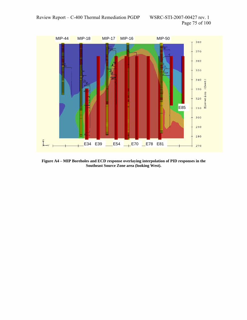
Review Report – C-400 Thermal Remediation PGDP WSRC-STI-2007-00427 rev. 1 Page 75 of 100
Figure A4 – MIP Boreholes and ECD response overlaying interpolation of PID responses in the
Southeast Source Zone area (looking West).
MIP-44 MIP-18 MIP-17 MIP-16 MIP-50
E34 E39 E54 E70 E78 E81
E85

Review Report – C-400 Thermal Remediation PGDP WSRC-STI-2007-00427 rev. 1 Page 76 of 100
Figure A5 – MIP Boreholes and ECD response overlaying interpolation of PID responses in the
Southwest Source Zone area (looking North).
MIP-35 MIP-03 MIP-04 MIP-07
E09
E10 E11E12E19
E20
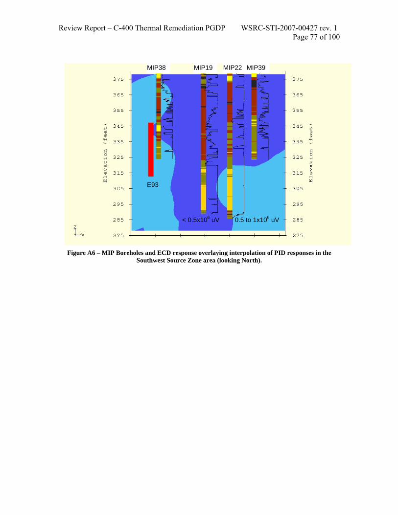
Review Report – C-400 Thermal Remediation PGDP WSRC-STI-2007-00427 rev. 1 Page 77 of 100
Figure A6 – MIP Boreholes and ECD response overlaying interpolation of PID responses in the
Southwest Source Zone area (looking North).
MIP38 MIP19 MIP22 MIP39
E93
0.5 to 1x10⁶ uV< 0.5x10⁶ uV

Review Report – C-400 Thermal Remediation PGDP WSRC-STI-2007-00427 rev. 1 Page 78 of 100
Appendix C Graphs of Trends and Concentrations in Monitoring Wells in the Vicinity of the
PGDP C-400 Building

Review Report – C-400 Thermal Remediation PGDP WSRC-STI-2007-00427 rev. 1 Page 79 of 100

Review Report – C-400 Thermal Remediation PGDP WSRC-STI-2007-00427 rev. 1 Page 80 of 100

Review Report – C-400 Thermal Remediation PGDP WSRC-STI-2007-00427 rev. 1 Page 81 of 100

Review Report – C-400 Thermal Remediation PGDP WSRC-STI-2007-00427 rev. 1 Page 82 of 100

Review Report – C-400 Thermal Remediation PGDP WSRC-STI-2007-00427 rev. 1 Page 83 of 100

Review Report – C-400 Thermal Remediation PGDP WSRC-STI-2007-00427 rev. 1 Page 84 of 100
Appendix D Modeling and Engineering Evaluation
D1.0 DESIGN BASIS The design basis for the implementation of ERH was derived from the calculated response of the subsurface to the application of electrical power and the extraction of fluids. To calculate this response, the contractor utilized a numerical simulation of the implementation of ET-DSP at the C-400 site. The simulations were performed with TETRAD, a commercially available multi-phase, numerical simulator originally developed for oil recovery. The simulations are described in Appendix B of the 90% Remedial Design Report (90% RD). This section provides an independent, general assessment of the major components of the design basis by comparing results of the simulations with order-of-magnitude calculations.
D1.1 Power Requirements The power applied and energy transferred to the soil for heating can be represented by:
R
V I R I V P2
2 === (1)
The RGA has an estimated resistivity of 103 ohm-m (per depth) and each electrode is 10 feet (3.05 m) long. The applied voltage across the electrodes is 480 V. The power applied to the soil over a 10-foot interval is then roughly:
( ) ( )( ) W818,6
m-ohm 103m .053V 480
RV P
22===
In the UCRS, the resistivity is estimated to be lower (consistent with its finer texture) with a typical value of 38 ohm-m (per depth). This lesser resistivity yields a maximum power input for a single electrode in the UCRS of about 18,500 W when applying a voltage of 480 V. Presumably, the power distribution system will automatically lower the applied voltage in the UCRS to about 290 V to yield a power input of about 6,800 W. This voltage reduction in the UCRS will allow a more uniform heating of the site. For a total of 336 electrodes each with a power input of about 6,800 W, the total power requirement is about 2,300 kW. This total power requirement is commensurate with the average value of 2,165 kW and the peak value of 2,812 kW determined from the numerical simulation presented in Appendix B (Table 1.3) of the 90% RD.
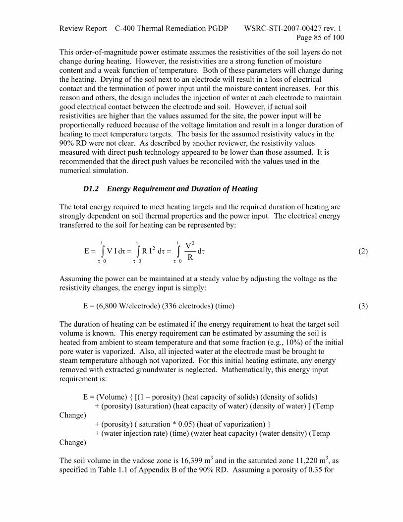
Review Report – C-400 Thermal Remediation PGDP WSRC-STI-2007-00427 rev. 1 Page 85 of 100
This order-of-magnitude power estimate assumes the resistivities of the soil layers do not change during heating. However, the resistivities are a strong function of moisture content and a weak function of temperature. Both of these parameters will change during the heating. Drying of the soil next to an electrode will result in a loss of electrical contact and the termination of power input until the moisture content increases. For this reason and others, the design includes the injection of water at each electrode to maintain good electrical contact between the electrode and soil. However, if actual soil resistivities are higher than the values assumed for the site, the power input will be proportionally reduced because of the voltage limitation and result in a longer duration of heating to meet temperature targets. The basis for the assumed resistivity values in the 90% RD were not clear. As described by another reviewer, the resistivity values measured with direct push technology appeared to be lower than those assumed. It is recommended that the direct push values be reconciled with the values used in the numerical simulation.
D1.2 Energy Requirement and Duration of Heating The total energy required to meet heating targets and the required duration of heating are strongly dependent on soil thermal properties and the power input. The electrical energy transferred to the soil for heating can be represented by:
∫∫∫=τ=τ=τ
τ=τ=τ=t
0
2t
0
2t
0
d R
V d I R d I V E (2)
Assuming the power can be maintained at a steady value by adjusting the voltage as the resistivity changes, the energy input is simply: E = (6,800 W/electrode) (336 electrodes) (time) (3) The duration of heating can be estimated if the energy requirement to heat the target soil volume is known. This energy requirement can be estimated by assuming the soil is heated from ambient to steam temperature and that some fraction (e.g., 10%) of the initial pore water is vaporized. Also, all injected water at the electrode must be brought to steam temperature although not vaporized. For this initial heating estimate, any energy removed with extracted groundwater is neglected. Mathematically, this energy input requirement is: E = (Volume) { [(1 – porosity) (heat capacity of solids) (density of solids)
+ (porosity) (saturation) (heat capacity of water) (density of water) ] (Temp Change)
+ (porosity) ( saturation * 0.05) (heat of vaporization) } + (water injection rate) (time) (water heat capacity) (water density) (Temp
Change) The soil volume in the vadose zone is 16,399 m3 and in the saturated zone 11,220 m3, as specified in Table 1.1 of Appendix B of the 90% RD. Assuming a porosity of 0.35 for

Review Report – C-400 Thermal Remediation PGDP WSRC-STI-2007-00427 rev. 1 Page 86 of 100
both zones, the total energy that must be transferred to the vadose zone is about 1,300 MWh and to the saturated zone 1,100 MWh. Assuming the water injected to the electrodes totals 56,607 m3 (Table 1.3), the energy required to heat this water to steam temperature is about 5,200 MWh. Hence the total energy to heat the target soil volume is about 7,600 MWh. The total energy input for the numerical simulation was 9,352 MWh; however, this total includes operations beyond the initial heating of the site for a total duration of 180 days. These values are reasonably close; however, the influx of cool groundwater from outside the target volume to replace volatilized pore water is not included. In addition, the extraction of energy in the form of steam or hot water has not been accounted for in a total energy balance. Substituting the estimated total energy input into equation (3) yields the following duration for heating: Time = (7,600 MWh) / (0.0068 MW) / 336 (4) Time = 3,326 hours = 139 days The design assumes an operational period of 80 to 90 days to attain the desired heating and a total operational period of 180 days. Hence, the heating may require longer than modeled to create a significant steam zone in the target soil volume but it still falls within the planned operational period. However, the most vulnerable assumptions in these calculations are neglecting a significant influx of cool groundwater into the RGA from outside the target volume and the extraction of energy. If a steam zone is created, buoyancy will bring cool water into the target volume as discussed in the next section and the energy to heat this water is not included in the energy balance as discussed in a later section on the numerical simulation. A significant risk exists that the deep RGA will not be heated to target temperatures. Conversely, the fine-grained soils of the upper McNairy could reach boiling conditions under the RGA; however, the low permeability may also prevent infiltration of water into the soil resulting in a large increase in the resistivity and limited introduction of additional energy.
D1.3 Radius of Steam/Bubble Formation around Electrodes The radius of influence for the formation of steam and contaminant bubbles around each electrode is critical to determining the number and spacing of electrodes to achieve the heating and remedial goals. The primary mechanism for contaminant mass removal is volatilization and extraction. The numerical simulator TETRAD was used by the DOE contractor to determine the design basis for the implementation of ERH at PGDP. However, as described in a later section, concerns exist that the outer boundary condition used in the simulation may not provide a realistic depiction of this boundary. This section provides a simple model to assess the radius of bubble formation around each electrode based on buoyant forces driving volatilized water and contaminant upward. After heating to create bubbling conditions, the upward velocity of vapors in the soil around the electrode is governed by Darcy’s law modified for two-phase flow. The modification results from the use of an “effective” permeability that is the intrinsic permeability, k, of the soil multiplied by a relative permeability, kr. The relative permeability is solely a function of the water saturation in the path of the vapor and will

Review Report – C-400 Thermal Remediation PGDP WSRC-STI-2007-00427 rev. 1 Page 87 of 100
vary with height because of gravity. The upward vapor velocity around the electrode is governed by:
⎟⎠
⎞⎜⎝
⎛ ρ−∂∂
µ−=− g
zPkkv v
v
v
r
where µv is the viscosity of the vapor at steam temperature, Pv is the vapor pressure, z is the vertical coordinate, ρv is the density of the vapor, and g is the gravitational constant. The horizontal velocity resulting from the injection of water at the electrode is negligible. For a given cross-sectional area, A, the mass rate is:
⎟⎠
⎞⎜⎝
⎛ ρ−∂∂
µρ
=ρ= gz
PAkkvAm v
v
v
rvv
At some height along the electrode, the driving force for the vapor flow is solely buoyancy. Mathematically, this condition is represented as:
gzP
zP
llv ρ=
∂∂
=∂∂
where ρl is the density of the liquid water and Pl is the liquid pressure. Substituting this expression into the mass rate yields:
( )gAkkvAm vl
v
rvv ρ−ρ
µρ
=ρ=
For steady state conditions with a specified mass vaporization rate, m, this expression can be rearranged to yield the cross-sectional area of the flow:
( )gkkm
Avlrv
v
ρ−ρρµ
=
Assuming the cross-sectional area is circular and designating the radius as R, the theoretical maximum radius of the steam zone in a uniform porous medium is:
( )gkkm
Rvlrv
v
ρ−ρπρµ
=
All quantities in this expression can be estimated except for the mass rate which must be related to the energy input. If we assume power into the electrode is perfectly translated into a steam generation rate during pseudo-steady operation, the energy E then yields:

Review Report – C-400 Thermal Remediation PGDP WSRC-STI-2007-00427 rev. 1 Page 88 of 100
fgh
Em =
Substitution into the expression for the radius yields:
( )gkkhE
Rvlrvfg
v
ρ−ρρπµ
= (5)
Values to estimate the radius of the zone of bubble formation around the electrodes in the saturated portions of the UCRS and the RGA utilizing equation (5) are provided in Table 1. The radii are plotted in Figure 1 as functions of the input power to the electrode. The electrode power is approximately 6,800 kW and, as indicated, the UCRS is expected to have a bubbling radius close to 10 feet. However, the high permeability of the RGA yields a radius less than 2 feet. These calculations are conservative because the model does not account for the somewhat uniform heating of the electrical power and lateral heat conduction. This simplistic model is most applicable at the bottom of the RGA since the top of the RGA is bounded by the lesser permeability of the UCRS. Hence, the results are cause for concern that heating the bottom of the RGA to steam temperatures may not be feasible. The influx of cool water replacing volatilized water will be very rapid and the energy requirements for heating very large. Extending electrodes into the top of the McNairy formation provides a good opportunity to extend the zone of bubble formation but replenishing the water in the McNairy pore space to prevent drying out may limit this effect.
Table 1 Parameter Values
Parameter Value
kr (-) 0.17
µv (kg/m/s) 0.0000126
g (m/s2) 9.81
ρv (kg/m3) 0.6
ρl (kg/m3) 958
hfg (J/kg) 2257000
UCRS Permeability (darcies) 1.5
RGA Permeability (darcies) 150

Review Report – C-400 Thermal Remediation PGDP WSRC-STI-2007-00427 rev. 1 Page 89 of 100
0
2
4
6
8
10
12
14
0 2 4 6 8 10Power Input (kW)
Rad
ius
of B
ubbl
e Fo
rmat
ion
(ft)
UCRSRGA
Figure D1. Estimated Electrode Radius of Influence in the Saturated Zone
This discussion on steam bubble formation does not imply that significant contaminant mass removal will not occur – even at the bottom of the RGA. The ERH pilot test achieved good results without such heating. Rather, the ITR team encourages a clear understanding of this issue and incorporate any results to avoid setting a heating metric that may not be achievable even when the primary objective of mass removal is realized. Further, the simplified calculation is not offered as a definitive method for electrode spacing. The ITR team supports the PGDP team approach of using a numerical model for the actual design. The simplified “radius of steam bubble formation” calculation emphasizes the importance of reducing uncertainties and assuring the conceptual basis of that numerical modeling.
D1.4 Heating by Steam Injection The 90% RD includes the use of a single steam injection to re-treat the area of the site previously host to the ERH pilot test. It is assumed the area has been re-contaminated by the influx of surrounding groundwater. This re-contamination has not been verified and the need to re-treat this soil volume has not been justified with field data. The shape of the steam front resulting from injection of steam into the RGA at the design rate of about 2,000 pounds per hour was estimated utilizing the model of van Lookeren (1983). The result of the calculation is illustrated in Figure 2. The steam zone exists around the injection well only above the red line and liquids exist below. This plot suggests that the bottom of the RGA will not be significantly heated by steam injection. Any DNAPL in this region will not be displaced and recovered. Further, attempts to mitigate this effect by screening deep in the RGA would not be successful as buoyancy and the path of least resistance would bring the steam zone to the top of the RGA before

Review Report – C-400 Thermal Remediation PGDP WSRC-STI-2007-00427 rev. 1 Page 90 of 100
lateral growth could be achieved deep in the RGA. The recommendation is to eliminate the steam injection activity and verify the area requires treatment before proceeding with any remedial action in this previously treated volume.
02468
101214161820
0 10 20 30 40Radius (feet)
Ste
am Z
one
Thic
knes
s (fe
et) Steam Zone
Condensate &Groundwater
Lower UCRS Acts as Confining Layer02468
101214161820
0 10 20 30 40Radius (feet)
Ste
am Z
one
Thic
knes
s (fe
et) Steam Zone
Condensate &Groundwater
Lower UCRS Acts as Confining Layer
Figure D2. Estimated Shape of the Steam Injection Front in the RGA
D1.5 Water Balance The numerical simulation report cites the total volume of saturated soil heated as 11,220 m3 with an approximate porosity of 0.33. Hence, the initial volume of water in this soil is about 3,740 m3 or about 988,000 gallons. For the numerical simulation, the remediation system was constrained to extract 5% more water than is injected and the forced flux (injection wells on the upgradient boundary and extraction wells on the downgradient boundary) were balanced. These constraints are evident in the modeling report where the total volume of water injected was 56,607 m3 and the total volume extracted was 59,439 m3. Hence, the simulation appeared to yield a net removal of 2,832 m3 or about 750,000 gallons. The ITR team was subsequently provided information that sufficient water to close the mass balance can be accounted for by also including the water entering from the constant head boundaries. The ITR team recommends that the project team complete their analysis of the water balance and a document a clear assessment of the ramifications of the hybrid boundary conditions (i.e., where is water actually entering or exiting the system?, did the parameter combination used partially isolate the treatment zone by allowing loss of injected water the upgradient specified flux boundary and input of water

Review Report – C-400 Thermal Remediation PGDP WSRC-STI-2007-00427 rev. 1 Page 91 of 100
from the downgradient specified flux boundary?). The ITR team recommends running the simulation using a specified pressure at an open boundary. This would develop a higher degree of confidence in the assumed hydraulic conductivity and heads and would allow examination of the significance of layering and other heterogeneities (i.e., it would not require fluxes to be uniform throughout the RGA.
D1.6 Numerical Simulations A number of issues assumptions were identified in the use TETRAD to simulate the application of ERH at the site. These include, but are not limited to:
• Soil permeability values used in the original 2D simulation were one order-of-magnitude higher than values provided by the site geologist (note that this has already been addressed by the contractor team during the writing of the ITR report),
• Lateral saturated zone boundaries were assumed to have a specified flux rather than a specified head, effectively isolating the heated soil volume from the surrounding aquifer (note that subsequent information indicates that both flux and head are specified),
• Contaminant recovery rates and total masses calculated in the simulation were not based on any site-specific data or conceptual site model, and
• A specified flow of air across the lateral boundaries of the vadose zone is forced to match the extraction rate of air (i.e., no leakage from the overlying surface) and the applied vacuum to achieve this flow will increase significantly if the appropriate permeability is utilized in the simulations.
D1.7 Soil Vapor Extraction in the Shallow Vadose Zone
The design of the soil vapor extraction system above the targeted soil volume for heating has little basis. No conventional air permeability testing or SVE pilot testing has been performed although the shallow vadose zone is suspected of harboring a large mass of contamination. The startup and shutdown of the SVE system is currently designed to coincide with the startup and shutdown of the ERH system with no regard for potential mass recovery rates that may exist at the end of the heating period. It is recommended that the SVE system in the vadose zone be operated independently from the ERH system in the deeper soils. A separate set of performance criteria should be developed for the operation of the SVE system. A pseudo-steady solution for confined, one-dimensional, radial air flow is available (Johnson et al., 1990) as an order-of-magnitude check for the design basis:
⎟⎟⎠
⎞⎜⎜⎝
⎛π
µρ+=
∞∞ r
rln
bkTRQ
P P wairairair22w (6)
where:
Review Report – C-400 Thermal Remediation PGDP WSRC-STI-2007-00427 rev. 1 Page 92 of 100
P = pressure r = radius [m] Q = volumetric flow rate ρair = density of air [1.20 kg/m3] R = gas constant for air [0.287 J/g/K] µair = viscosity of air [0.000018 kg/m/s] T = temperature [293 K] b = interval thickness [m] k = permeability [darcies] Rearranging yields the extraction rate for a specified extraction well vacuum and effectively infinite radius:
( )
⎟⎟⎠
⎞⎜⎜⎝
⎛µρ
π−−=
∞
∞
rr
lnTR
bkP PQ
wairairair
2w
2
For a permeability of 0.3 darcies and a generous radius of vacuum influence of 10 m, equation (6) suggests the maximum flow from a shallow extraction well is about 4 scfm for an applied vacuum at the wellhead of 0.5 atmospheres. The design rate cited in Table 1.2 of Appendix B is 8 scfm per well. Hence, the extraction rate from the shallow zone may be half the design rate. A combined SVE pilot test (e.g., 48 hours) and air permeability test are strongly recommended to allow proper design of a vapor extraction and treatment system. A properly designed SVE system may be capable of achieving a source reduction in the vadose zone on par with the source reduction in the saturated zone from ERH. D2.0 ABOVEGROUND TREATMENT SYSTEM DESIGN The design basis described in the previous section provides the anticipated capacities required of the aboveground treatment system for vapors and liquids extracted from the subsurface. This section provides an assessment of the process design.
D2.1 Power Supply and Distribution The electrical power supply and distribution system appears to be state-of-the-art and capable of automatically directing power to soil horizons with inadequate heating. However, the power delivered to the subsurface will be limited by the supply voltage and soil resistivities. No recommendations required.

Review Report – C-400 Thermal Remediation PGDP WSRC-STI-2007-00427 rev. 1 Page 93 of 100
D2.2 Water Supply and Distribution
The water supply and distribution system appears to be adequate. No recommendations are required.
D2.3 Steam Condensation Steam extracted from the subsurface in the vapor extraction wells will be directed through an indirect, water-cooled heat exchanger (E-101) to condense the steam. Most indirect heat exchangers suffer from a relatively large pressure drop and the vacuum attained at the extraction wellheads may suffer. Indirect condensation of steam under a high vacuum is also generally inefficient and the non-condensable flow of 1,200 scfm will require this unit be quite large and the flow of cooling water will also be large (e.g., on the order of 750 gpm) to condense the design rate for steam extraction (3,000 pph). Recommend investigating the use of a direct contact steam condenser utilizing treated and cooled water extracted from the subsurface to mitigate the pressure drop through the heat exchanger and the need for a huge flow of cooling water.
D2.4 Non-Condensable Vapor Treatment Vapor treatment after steam condensation will be achieved with compression followed by cryogenic condensation of TCE. This process can be very effective but scaleup to a large system such as that for C-400 does not provide any benefit as the system will consist of 10 or more units operating in parallel. The drawback to this approach is increased maintenance requirements but this is offset by the flexibility to operate only as many units as required and the ability to service units individually without shutting down the system.
D2.5 Water and Condensate Treatment The process design indicates air stripping will be used to treat the water before discharge. The air flow rate to the air stripper is indicated to be 300 scfm in Drawing Number P7DC40000A001 of the 90% RD. This air flow appears to be about half the flow necessary to treat a water flow of 87 gpm. If increased to 600 scfm (to ensure meeting water discharge requirements), the total vapor flow rate requiring treatment will increase from 1,500 scfm to 1,800 scfm. A higher flow may require additional compression/cryogenic condensation units to meet the increased flow requirement.
D2.6 Process Controls Process controls were not adequately described in the 90% RD for an evaluation. At a minimum, the control and interlock logic and other requirements should be tabulated and discussed in the 90% RD.

Review Report – C-400 Thermal Remediation PGDP WSRC-STI-2007-00427 rev. 1 Page 94 of 100
D3.0 STARTUP & OPERATIONS As currently planned, ERH in the three target areas and the aboveground treatment system will all be turned on simultaneously. This approach is likely to result in a number of false starts as parameters for the long-term operation are developed. In addition, the collection and interpretation of early data will be challenging. For these reasons, a phased system startup, as described below, is recommended.
D3.1 Phased Startup A logical plan to phase the startup of the treatment system and ERH components is highly recommended. Installation and operation of the three source treatment zones in a sequential manner is preferred to climb the learning curve and reduce the required capacity of the treatment system; however, this approach is likely not feasible because of site access constraints. Assuming the system is installed in all three treatment areas simultaneously and after commissioning the aboveground treatment system, the following steps could be followed to reduce the difficulties and confusion at startup of the operations:
1. Initiate vapor extraction in the vadose zone at the design flow rates for ERH and fine-tune operation of the vapor treatment system
2. Initiate pump-and-treat of groundwater at the desired extraction rates for the ERH operations and fine-tune operation of the water treatment system
3. Collect data documenting the contaminant mass removal rates via groundwater and vapor extraction to provide a baseline for assessing the enhancement provided by ERH
4. Initiate heating in the first area of the site 5. As the first area stabilizes into a relatively steady heating mode, initiate the
second area 6. As the second area stabilizes into a relatively steady heating mode, initiate the
third area
D3.2 Contingency Plans A primary concern for operation of the system is the ability to heat target soil volumes to target temperatures. If the ERH electrodes are installed in all three areas simultaneously, no opportunity will exist to optimize placement of the electrodes based on field observations in a first area. The pilot test was inconclusive regarding the ability of ERH to heat the RGA down to its interface with the McNairy Formation. A contingency should be in place to add electrodes if insufficient heating is achieved near the interface. The soil resisitivities will change during the heating. A plan of action should be developed if the progress of soil heating falls far behind schedule. If actual soil resistivities are higher than the design values, the power input will be proportionally reduced because of the voltage limitation and result in a longer duration of heating to meet temperature targets.

Review Report – C-400 Thermal Remediation PGDP WSRC-STI-2007-00427 rev. 1 Page 95 of 100
Installation of the electrodes and extraction wells is likely to uncover additional accumulations of contamination. A contingency should exist to address such accumulations. Adverse migration of DNAPL as a result of heating in the UCRS is possible. The heating could yield a mobilization of DNAPL that drops from the UCRS into the RGA and onward to the McNairy interface if sufficient mass is mobilized. A plan of action for assessing the occurrence of such migration is recommended as the downward migration of DNAPL will increase the difficulty and cost of removing the contamination. A comprehensive list of risks and potential contingencies should be developed.
D3.3 Phased Shutdown After heating of the subsurface has met performance objectives, mass removal objectives for various areas and horizons of the site should be implemented. In particular, extraction should not cease while the site continues to hold significant energy. The residual energy in the heated soil can contribute to additional mass removal if the groundwater extraction and vapor extraction operations continue to a point of diminishing returns for source reduction. Individual termination criteria should be developed for the UCRS and RGA in each of the three treatment areas. Continued operation of the SVE system in the vadose zone should be considered even after the site cools if a cost-effective mass removal rate is achieved.

Review Report – C-400 Thermal Remediation PGDP WSRC-STI-2007-00427 rev. 1 Page 96 of 100
Appendix E
Cost Evaluation The Independent Technical Review (ITR) team was tasked with determining if the costs associated with the treatment system, as specified in the 90% Remedial Design Report (PRS, 2007a), were reasonable and commensurate with other governmental remediation projects of similar scope, size, and duration. This involved reviewing the cost estimate that was prepared by Paducah Remediation Services (PRS) for installing and operating the Electrical Resistive Heating (ERH) thermal treatment system at the C-400 Cleaning Building and comparing those estimated costs to the thermal treatment costs reported at other federal facilities. PRS initially provided a cost estimate that was dated 12 April 2007 and had the title “PAD Groundwater C-400 Action.” The estimate was divided into various categories that designated the type of activity (e.g., above ground treatment, installation and operation, etc.). The ITR team used this 12 April 2007 cost estimate to estimate the various costs associated with project oversight and management, site specific costs, and costs associated with the thermal treatment system. Grouping costs according to these broad categories facilitates the comparison to ERH projects completed at other federal sites in the United States. Project oversight and management along with site specific costs are important for completing the interim removal action at the C-400 Cleaning Building; however, they are specific to site conditions and are not necessarily comparable to other thermal treatment sites. For example, most sites don’t require radiation technicians or a dedicated security detail. Additionally, treating and disposing of waste materials generated during the installation and operation of the thermal treatment system is expected to cost more than at a typical contaminated site given the presence of radioactive isotopes in the subsurface soils at Paducah. Some of the key findings from the review of the April cost estimate included:
o In comparing the proposed remedial action at Paducah to previously treated sites throughout the country, the ITR team found that Paducah is a large project with overall costs greater than any project previously attempted.
o A dominant cost for thermal treatment at Paducah (43% of the total) was associated with the drilling required to install the electrodes and monitoring points. The ITR team recommended reducing the drilling costs to levels that are closer to industry norms (less than $200/ft).
o The estimated ERH equipment and support infrastructure (in terms of cost per electrode and cost per treated volume) were within the range of previous projects (but near the high end of that range).
o Other ITR team recommendations based on that initial evaluation encouraged cost reduction associated with site specific categories: waste handling and project support/management.
After reviewing the ITR team findings, PRS reported that the 12 April 2007 estimate represented costs associated with a baseline technical approach rather than the specific

Review Report – C-400 Thermal Remediation PGDP WSRC-STI-2007-00427 rev. 1 Page 97 of 100
system described in the 90% Remedial Design Report. The 90% design differed from the baseline approach in the number of electrodes and method of off-gas treatment, among other changes. PRS provided a revised cost estimate dated 18 July 2007 that reflected the costs for the system as described in the 90% Remedial Design Report (note that the updated estimate was deemed business sensitive and was provided to the cost evaluation subject matter experts of the ITR team on 02 August 2007 for evaluation ). The revised estimate is summarized In Table E1 (with costs lumped into broad categories suggested by the ITR team -- project management and oversight, thermal treatment, and site specific costs associated with sample analysis and waste management). The updated total estimated cost was approximately 12% higher than the April baseline.
Table E1 – Summary of Estimated Costs Baseline (12 April 2007
estimate) 90% remedial design (18
July 2007 estimate) Category percentage of total percentage of total
Project oversight and management 8% 6% Sample management and analysis 3% 6% Waste management and disposition 11% 21% Thermal treatment (includes drilling, construction and operation; excludes electrical power)
78% 67%
Total Project Cost (approx) $17,500,000 $19,700,000 Comparing the costs for the baseline approach to the costs for the 90% remedial design shows that the estimated costs for sample management and analysis along with waste management increased while the cost for project oversight and management and thermal treatment decreased (Table E1). These differences may be due to assumptions that the ITR team employed in sorting the baseline approach costs into the four categories shown in Table E1 but are also due to changes in the 90% remedial design. For example, there was an increase in the number of electrodes from 272 for the baseline approach to 336 for the 90% remedial design, which meant increasing the number of borings from 68 to 109. In addition, the off-gas treatment for the baseline approach was by catalytic oxidation whereas the 90% remedial design uses cryogenic condensation. The following two sections update the ITR team evaluation based on the revised cost estimate of 18 July 2007. E.1 Comparison of the Estimated Paducah ERH Thermal Treatment Cost to the Cost Reported for Federal Sites The estimated cost for the ERH thermal treatment system at Paducah includes purchasing and installing the above-ground ERH equipment, installing electrodes and other subsurface infrastructure, installing and operating the above ground liquid and vapor treatment system, and materials to operate the treatment system, but excludes cost for electrical power. Several contracts and vendors are included in this overarching estimate (thus the costs presented here can not be attributed to any particular contract or vendor).

Review Report – C-400 Thermal Remediation PGDP WSRC-STI-2007-00427 rev. 1 Page 98 of 100
To determine if the costs for the remedial action at C-400 were reasonable and commensurate with other remedial projects requires calculating the cost per volume of subsurface treated (for consistency with the bulk of the background literature, the costs will be calculated in $ per cubic yard). The estimated ERH treatment costs combined with the target subsurface volumes that were documented in the 90% RDR, yield an approximate total ERH estimate of $370 per cubic yard (excluding electrical power). To compare the C-400 remediation to historical sites, an estimate of the costs of power need to be added to this base estimate. The electrical costs can be approximated using the 90% RDR power estimates for subsurface heating and surface operations and assuming an approximate energy cost of $41 per megawatt hour (EIA, 2007). The resulting power costs for the remediation are approximately $20 per cubic yard, resulting in a total ERH system cost of approximately $390 per cubic yard. To our knowledge, there is no independently verified cost information available for thermal treatment projects completed to date. One available document provides relatively complete cost information for project management and oversight and site specific costs in addition to the thermal treatment costs (Gavaskar et al, 2007). Most other sources, including EPA’s “In Situ Thermal Treatment Site Profile Database,” contain cost information provided by the thermal treatment vendors (often excluding project management, oversight, waste disposal, and monitoring costs). For example, the MCB Camp Lejeune Site is reported to have cost $65/cubic yard according the In Situ Thermal Treatment Site Profile Database entry, however, Gavaskar et al. 2007 report $113 per cubic yard based on an independent analysis of the cost data provided by the U.S. Navy. Another inconsistency was noted for the Pinellas STAR site where the thermal treatment vendor provided the USACE with a cost of $1.3 million to treat 12,963 cubic yards for a cost of $100 per cubic yard. However, Butherus et al., 2004 who represented the DOE for the Pinellas project, stated the thermal treatment subcontract cost of the project was approximately $3.8 million equating to a unit volume cost of $290 per cubic yard. The ITR team evaluation (Table E2) is based on the information summarized by Gavaskar et al (2007) since this information appears to be the most equivalent to the relatively complete cost estimation that has been performed to support the thermal remediation at the C-400 Building. The normalized cost for ERH thermal treatment at the six sites listed in Table E2 ranged from a low of $100 per cubic yard at Pinellas to a maximum of $544 per cubic yard at Alameda Point with the estimated cost at Paducah of approximately $390 per cubic yard falling within this range. The ERH system described in the 90% Remedial Design Report (PRS, 2007a) is one of the larger thermal treatment projects presented in Table E2. While the cost per cubic yard might be expected to decrease with increase in subsurface volume treated due to increasing economies of scale, that trend is not apparent from the data presented in Table E2. The cost at NWIRP Bedford, MA and Naval Complex Charleston, SC, which had similar subsurface volumes of approximately 5,000 cubic yards, were relatively low ($150 to $200 per cubic yard), while the cost at Alameda Point with a similar treatment volume was the highest cost site at approximately $544 per cubic yard. Based on the updated cost estimates, Paducah cost were exceeded by Alameda Point on a normalized per volume basis. As discussed above, PGDP specific issues (such as

Review Report – C-400 Thermal Remediation PGDP WSRC-STI-2007-00427 rev. 1 Page 99 of 100
radiation control and the associated health protection) are somewhat unique and these factors would tend to result in relatively high project management, oversight, and site specific costs when compared to the other tabulated sites.
Table E2: Selected Electrical Resistive Heating (ERH) Site Treatment Costs
Site Max. Depth
(feet bgs)
Volume (cu. yard)
Management & Oversight
Site Specific (waste,
monitoring, etc.)
Thermal Treatment
Cost per cu. yard
NWIRP Bedford, MA (p. 15)1 60 4,148 $348,000 $66,675 $658,100 $158
Naval Complex Charleston, SC (p. 60)1 10.5 5,000 $215,000 $50,000 $1,009,000 $202
Alameda Point, CA (p. 77)1 19 4,943 NR $750,000 $2,690,723 $544
MCB Camp Lejeune, NC (p. 98)1 22 12,926 NR $355,685 $1,722,641 $113
Fort Lewis, WA (Table 7-2)2 NR 80,000 NR NR NR >$200
Pinellas STAR, FL (p. B-18)2 35 12,963 NR NR $1,300,000 $100
Paducah, KY (approximate estimates) 100 35,600 $1,200,000 $5,400,000 $13,800,000* $390
1Gavaskar et al., 2007, 2USACE, 2006, NR: not reported, *approximate including electrical power costs Another normalized metric used for comparing ERH thermal treatment costs between sites is the cost per electrode. There are 336 electrodes to be installed at Paducah with an overall price per electrode of approximately $40,000. By comparison, there were 101 electrodes used at Charleston for a per electrode cost of $9,990, 91 electrodes used at MCB Camp Lejeune for a per electrode cost of $18,930, and Alameda Point used 52 electrodes for $51,745 per electrode. As with the cost per cubic yard, the per-electrode cost at Paducah is bounded by past costs and near the upper end of the reported range. E.2 Waste Handling and Disposal The costs for waste management and disposition are a significant fraction of the overall estimated project costs (21%, Table E1). The waste management plan, contained in the Remedial Action Work Plan (PRS, 2007b), describes the volume of waste that will be generated during the installation and operation of the ERH thermal treatment system. While most of the waste will be treated and stored on-site, it is the waste that has to be transported off-site which represents a large percentage (approximately 44%) of the waste treatment cost. The solids that are generated during the completion of soil borings represent the majority of waste designated for off-site treatment. The volume of soil cuttings and sediment from decontamination will be contained in 1,400 55-gallon drums. It was estimated that 68% of this waste will require off-site treatment and disposal as

Review Report – C-400 Thermal Remediation PGDP WSRC-STI-2007-00427 rev. 1 Page 100 of 100
mixed waste containing TCE DNAPL and radioactive isotopes. Given that soil samples will be collected from each 55-gallon drum and analyzed to determine if off-site treatment is required, the cost associated with waste disposal may change significantly depending on the number drums that meet the requirement for treatment prior to disposal. With a treatment and disposal cost on the order of $1,000 per 55-gallon drum, the importance of properly labeling, tracking, and categorizing each of the 1,400 drums should be emphasized. The off-gas treatment for the baseline approach was catalytic oxidation whereas the 90% remedial design uses cryogenic condensation and the costs have been updated to reflect the technology selection. A significant waste disposal cost (11.5% of the total waste treatment costs) is associated with the 75,000 gallons of TCE DNAPL expected to be recovered from the subsurface as the result of thermal treatment operations. Currently this waste is designated for off-site treatment and disposal. The ITR team recommends that the site consider solvent recycling as an option rather than disposing of the TCE DNAPL as hazardous waste. Updated ITR Team Assessment The ITR team commends the PGDP team for the significant efforts made to refine and improve the cost estimates for the C-400 Building remediation. The revised costs (18 July 2007) adequately address many of the previous recommendations (e.g., drilling costs are now well below $200 per linear foot). Thus, those initial ITR team recommendations are no longer relevant. The updated cost related summary recommendations are as follows: Overarching Recommendation: The ITR team determined that the estimated cost for ERH thermal treatment at the C-400 Building is within the range of thermal treatment costs at other federal sites on a per treatment volume and per electrode basis. Nonetheless, the cost is near the upper end of the historical range and further cost refinement and cost reduction opportunities should be pursued as the project plans are finalized. Recommendation a: The costs for waste management and disposition are a significant fraction of the overall estimated project costs. With a treatment and disposal cost on the order of $1,000 per 55-gallon drum of solid waste, the importance of properly labeling, tracking, and categorizing each of the anticipated 1,400 drums should be a priority. Recommendation b: Currently, the 75,000 gallons of TCE DNAPL expected to be recovered from the subsurface as the result of thermal treatment operations is designated for off-site treatment and disposal. The ITR team recommends considering solvent recycling as an option rather than disposing of the TCE DNAPL as hazardous waste.