Embed Size (px)
Citation preview
REVIEW OF WORK DONE BY SOUTHWEST RESEARCH INSTITUTE
ON THE STORAGE OF AUDIO TRANSCRIPlION MATERIALS
Presented at
Project Long-Fi Conference washington D C
October 15 1958
SOUTHWEST RESEARCH INSTITUTE
SAN ANTONIO TEXAS gt
I INTRODUCTION
The approach to this problem has been f
1 To catalogue the manifestations of shelf aging of phonograph
discs and magnetic tapes which decrease their value as audio
transcriptions
2 To catalogue the basic mechanisms of degradation that result
in the aforementioned manifestations
3 To seek means compatible with library operation of eliminating
I or inhibiting the action of these mechanisms of degradation
The scope of this study has been limited to the alreaqy mentioned
I I objectives and does not include such studies as those of playback deshy
gradation and development of longer lived audio transcription materials
In addition the realities of library operation precluded study of
technically sound but nevertheless impractical techniques such as lowJ
) temperature storage in an inert atmosphere Actual program work has
1 been a compromise between theoretical research into the nature of audio
transcription materials and an investigation of the utility of increasing
their shelf life by practical measures This study has been made by a
I combination of literature search theoretical analysis and laboratory
work The findings have in one respect been prosaic in that such proshy
J blem solutions as novel anti-aging coatings have not been developed
but the findings do clearly demonstrate that proper storage techniques J
and environments will increase considerably the storage life of audio
transcriptionsJ The northeast book stack area of the Library of Congress was
J
I
chosen as a typical library environment for this study Remembering
that audio transcription materials are organic materl als the preliminary
evaluation of this library environment indicated that three primary
factors of deterioration should be investigated--heat moisture and dust
Deteriorative agents to be investigated were biological chemical and
physical One would expect the biological agent to be fungi and that
such deterioration would be evidenced by surface marring One would
expect the chemical agents to be o~gen atmospheric contaminants
water incompatible ingredients of packaging materials and internal
chemical changes and that such deterioration would be evidenced by
changes in the physical properties of the material itself One would
expect the physical agents to be heat water dust and stress and )- i
that such deterioration would be evidenced by surface marring and dimenshy
sional changes
An obvious approach to the study of increasing the longevity of
audio transcriptions by storage technique and environmental control was
therefore taken consisting of
1 Sampling of the stacks and inspection of degraded records
2 Exposing new records to the agents of deterioration in
I accelerating environments i~
3 Investigating more completely the agents which caused the
J most deterioration in the tests or which duplicated the
deterioration found in sampling J
-lI-The rate of deterioration caused by an agent (such as fungi or oxidashy
1 tion) is accelerated by changes in an environmental factor (such as heat or moisture)
] 2
]
I I
4 Investigating means of eliminating or inhibiting deteriora-
I I tion of the records by operating on the environmental factors
or agents or by changes in storage techniques
The results of this approach indicate that improving the existing
) storage environment and use of appropriate storage techniques will mashy
terially increase the shelf life of audio transcriptions stored therein
I Since each of the materials poses a different set of pro blems the reshy
commendations for such improvement of environmental control are presented) in the discussion of the individual audio transcription media which
] follows
]
]
]
]
]
) J
3
J
i - -
~ -bullbull I~ I
J shy I
I
~ c
i
i
DISCS
A proper classification of discs seems to be one based on their
type of construction ie
1 Laminate consisting of a structural core with a thermoshy
plastic coating The only currently made laminate discs
are the acetates which have an aluminum core and a nitroshy
cellulose lacquer coating Acetates are used for instanshy
taneous recording or as masters in the production of pressshy
ings Glass was used as a core material during World War II
Many of the early press1ngs were laminate discs using a
cardboard phenolic plastic or other rigid material for the r II
core and a shellac coating into which the grooves were
pressed Collections contain examples of all of these
types
2 Composition consisting of an aggregate with a thermoshy
plastic binder Most of the currently made 78 RPM norshy
mal groove records are of this type using calcium carbonate
(crushed limestone) and carbon black as the aggregate and
the copolymer of vinyl chloride - vinyl acetate as the binder o
It is common to replace some of the copolymer with such]
materials as Vinsol or Valite (cellulosic byproduct resins)
The greatest number of shellac discs were composition type
The discouraging feature of shellac discs from a storage
viewpoint is the common practice of using such materialsJ as sawdust and clay for the aggregate and the use of a wide
] j
1
1 variety of waxes and resins in the binder Often a shellac
1 disc contains no shellac at all The usual composition forshy
] mulation uses 30 or less by weight of binder In 1949
60 of the discs pressed were of the composition type This
J formulation is becoming less common because it is not satisshy
factory for LP low noise pressings] Plastic consisting of a plastic with less than 25 by weight
of filler This type of disc is only about 20 years old but] is the most common typ3 of pressing today The plastic ma
1 terial is usually the copolymer of vinyl chloride - vinYl
acetate and it is ro t unusual to extend it as much as 25I with such materials as Vinsol or Valite although the finest
records are unfilled and unextended Polystyrene has been]
I
used for the past five or six years instead of the copolYshy
) mer by some companie~ because it can be injection molded
(Decca is presently making LPs of pOlystyrene)
The discs studied in this program are
I 1 Laminate - instantaneous acetates
2 Composition - shellacs
I 3 Plastic - vinylites
The basis of this selection was not only that of choosing the more common
1 1 types of disc for study but also recognition of the fact that a libshy
rarian cannot identify and care for discs in more detailed categories
than these
] 2
J
1
I 1 I I I I )
) ~i ~( bull J I
I
rmiddot j t 4laquo
J
J
J
J
J
I J
J
j
THE ACETATE DISC
Most audio transcription media have been in use for a shorter
time than the potential storage life of the materials from which they
are made As a result there is little knowledge available from expershy
ience which can be used as a guide for determining optimum storage techshy
niques and environments for these media However this is not quite true
for the acetate disc as there are many examples of acetates which have
failed under good library storage conditions This indicates ~hatthe
potential stora~e l11e Qf these discsis not much longer than thelength
of time this type of disc has been inusej and also that especial care
must be taken of these discs
Warping and non-uniform deformation of these records is not a
pro blem because of the strength of the core Maintenance of vertical
storage attitude constant temperature and humidity environment preshy
vention of surface imprint from gravity loads and prevention of surface
marring from the sliding of material across the disc surface should
provide adequate protection against the physical agents of deterioration
The short potential life of acetate discs is due to their chemishy
cal formulation Acetate disc coatings are made of nitrocellulose
plasticized with castor oil and both of these materials are extreme~
susceptible to both chemical and fungal deterioration Most of the
failures observed in this stuqy were due to loss of plasticizer and this
will be discussed first
Castor oil is a non-solvent plasticizer (sometimes classified as
a softener) which is dispersed in the nitrocellulose in discrete droplets
j
]
] The loss of this plasticizer causes shrinking and embrittlement of the
] coating even if no chemical change has occurred in the nitrocellulose
Under optimum storage conditions this plasticizer is lost by the very
J slow process of oxidation to form volatile compounds which diffuse from
the coating This rate of plasticizer loss can be accelerated tremendousshy] ly by heat moisture wicking or fungal consumption Under the influence
] of heat the castor oil droplets often coalesce into large aggregates
as a result of internal diffusion and ultimately sweat outlt or exude
] middotmiddotHigh humid ty increases the rate of this diffusion Plasticizer loss
was the only source of degradation which affected fidelity noted after] subjecting these records to the accelerated aging tests
The accelerated aging tests were performed as indicated in the] following schedule
] 1 Constant Temperature and Humidity Tests
Discs Tested~~ Temp Time Humidity Air Remarks] RH I
Circulating Noise + 4 dhHc2-AX and 2-AY 1 mo]
Circulating No chg in freq or2-BX and 2-BY 1 mo
I
] j rdistortion some~-r
coa ting failure
2-AX and 2-AY l500 F 1 mo 90 Circulating Noise + 7 db
] 4-BX am 4-BY l500 F 1 wk gt90 stagnant Coating failure
2-AX and 2-AY l200F 1 mo gt 90 Stagnant Coa ting failure
J 2-BX and 2-BY l500 F 1 mo lt 10 Circulating No chg in freq or distortion
J 2-AX and 2-AY l500F 1 mo bull lt10 Stagnant Noise + 7 db after removing oil
2
]
]
J 2 Constant Temperature with Humidity Changed Each 24 Hours shy
Air Circulating] Discs Tested
] 2-fX and 2-AY
] 2-AX and 2-AY
2-BX and 2-BY
]
Temp Time High Low Humiditl Humidity
120degF 1 mo gt90 ( 10
150degF 1 mo gt 90 lt10
1500 F 1 moo gt90 lt10 J ~ 1 ~
Remarks
Noise + 4 db
Noise + 7 db
No chg in freq or distortion
3 Constant Humidity with Temperature Changed Each 24 Hours shy] Air Circulating
Discs Tested~lt High Low Time Humiditl Remarks] Temp Temp
2-AX and 2-AY 120degF -40degF 1 mo lt10
] 2-BX and 2-BY 1200 F -40oF 1 mo lt10
1
] 4 uv Exposure Only 0lt 700 F and 50 RH
2-BX for 1 month no change in frequency
] - unmodulated groove disc
] B - test frequency disc
x - new disc]
No change
No change l
j r l
distortion or noise
Y - new disc exposed to 24 hours Ultraviolet light before test
-Hlt Noise level is in relation to first play noise of new disc] These accelerated aging tests were made for the purpose of detershy
mining significant mechanisms of degradation and the manifestations of de-
J gradation which affect the playback fidelity of the discs No attempt
was made to determine degradation rates of the discs in typical storage
] environments because (1) of the experience data available on these discs
] 3
]
1
(
[ bull
which enable rational predictions of longevity to be made and (2) it was -
I
I estimated that acquisition of the empirical data required to determine
gt1 reaction and diffusion rates would be too expensive and time consuming t ~ ~- ~
~ for this program It should be noted however that qualitatively ~
~- ltI ~ manifestations of accelerated aging are the same as the manifestations ~ ~~
of ordinary shelf aging As indicated by Latham(l) and private communi-
I ~ ~tions ~others~~etat discs to retain their frequenc-seseem
)~~ and distortion characteristics until failure of the coating while thereI lt~ bull )~j is an increase in noise level occasioned by loss of Plasticizer~Under
I uncontrolled storage conditions coating failure may occur in ten to j
twelve years while under good storage conditions an acetate disc may
I I
exhibit only an increase in noise level of the order of 6 db in that
time and the coating should
of 25 ears ) (U- gt (I
I During exposure and cycling selected grooves were periodically
replayed and at the end of the exposure or cyclinamp previously unplayed
I I
grooves were played Measurements of noise were made on the unmodulated
groove discs and measurements of frequency response and distortion were
made on the frequency test discs It was found that there was no meashyo
I surable change in frequency response or distortion until ca~astrop~~~ ~ ~
failurEL ofJ_le coating In the replayed grooves the noise fell to I ~]L I HI1t gt
i
J about one~third of the first play intensity and remained at that low
]
11
intensity during the remainder of the test In the unplayed grooves
after 30 days exposure or 20 cycles it was found that the noise level
J
had risen to from 4 to 7 db relative noise level based on the first
play of the other grooves This was associated with a loss in weight
J (latham ~ S Tape Life U S Navy Underwater Sound Laboratory
IRE Convention Record 1955 National Convention Audio III Seminar Magnetic Recording by the Engineerbull
gt1) if A fl I ) ~ ~
J 11 ) 1 rtgt t j I I
1middotj(f _ r_ V~ y IJ I f ) ~ I
~~~J((JIIrlmiddot Jh 11 I I middotIP ~-J ~lJ It
)lgt~llh~~~i~c The results were erratic and failure of the coating occurred v~ Ii ) If rl I r
QV flr~Jflmiddoto~~ in the high~~~~y environments Since both failure and increase
- d X J f(1nnoise appeared to result from loss of plasticizer some further testsJ 1 iL i ~ yV 1-- ti f
j l~ J were made to check this assumption Acetate discs were exX)sed to the
j 1) Xitgt ~L elevated temperatures in stagnant air of low and high humidities The fyrVi ~ ~
~ discs exposed at low humidity developed an oily film on their surface
~~Ch could be removed either by washing or by ePosing them to circulating
~ ~ air After this film was removed from the disc surfaces thelr playbackJ J 1
~ I ~~ behavior was the same as if they had been previously exposed in circulating I ~c r 3J ~J ~~ ~~ (st T~e discs exposed at high humidity at first exhibited the same beshy
~ If ~ l~ havior as those exposed at low humidity and then failed by loss of adhe-
J ~ ~ z sion shrinking and cracking embrittlement and the development of minute
) ~~~~JpinholeS in the surface At the high humidities so much plasticizer was -~ -~ middotf
i 1l t~1 i exuded that it could not be removed as could the film on the surface of ~ ~
] ~ ~ ~ l ihe low humidi ty discs t f bull 3 t I bull
~~ 1
The end result of loss of plasticizer closely duplicates the failures]
] observed in many stored acetate discs as well as the increase in noise to
signal ratio observed in aged acetate discs In addition to the accelerashy
tion of plasticizer loss by heat and moisture castor oil is readily conshy
1 sumed by fungi In some cases there may be no surface evidence of this
action (such effect was noted by the Army Quartermaster Corps who were
]
l stu~ing the embrittlement of raincoats compounded with a fungi nutrient
plasticizer) or there may be visible surface damage to the disc A minor
cause of increase in rate of loss of plasticizer may be occasioned by the
] -wickingaction of porous material in contact with the disc surface The
first precaution to be taken in the storage of acetate discs is to reduce
]
]
i ~ k I
I i
t~ J
I
rate of loss of plasticizer to a minimum It would be of benefit to
I deny access of oxYgen to the discs if this were feasible or necessary
in certain exceptional cases shy
Too next most important mechanism of chemical degradation of the
) acetate disc is degradation of the nitrocellulose itself This was not
judged to be of importance in the accelerated aging tests because while
J Ultraviolet exposure accelerates the denitration reaction there was no
noticeable change in playback or coating failure characteristics between1 the exposed and unexposed discs In long time storage however the deshy
1 gradation of the nitrocellulose is of importance as was demonstrated by
1
too chemical analysis of a naturally aged disc These reactions result
J in the reduction of molecular size with a consequent change in mechanical
properties The two reactions of importance are thermal and hydrolytic deshy
composition ultimate degradation is evidence by extreme fragility The
] r ~Only way to lower the rate of these reactions is to use lower temperashy
tures and deny access of moisture to the disc
1 Cellulose nitrate is also consumed by fungi and their excretions
etch the disc surface It is not consumed as readily as is the plasticizerJ
1 but the etching effect can be severe as was shown in a test in which fungi
were grown on corrugated cardboard placed in contact with an acetate disc
The corrugation pattern was etched into the disc surface and the marring
was much more pronounced than that from fungi growing less profusely on
the disc surface itself
Two items of especial interest were noted in the survey of acetate
discs in storage First noticeable degradation of an acetate disc is not
usually a slow progressive development of embrittlement but usually a
6
I ~
sudden catastrophic failurepf the coating Second premature failure
I -----~
I of these discs seems to be common It is believed that both of these
phenomena result from accelerated loss of plasticizer which may be ocshy
casioned by fungal action or by a short time exposure to excessive tem-
I peratures in transit between factory and user
To summarize our findings on the storage of acetate discs
I 1 The surface should be protected from imprint or marring jLlL ci -
Rate of loss of plasticizer should be reduced to a minimumI feasible value
I Thermal and hydrolytic decomposition of cellulose nitrate
should be kept at a minimum
I The recommendations for accomplishing this are
When a disc is acquired it should be conditioned for approxi-I
mately 24 hours in an atmosphere of 50 plusmn 10 RH at 70 plusmn 5oF
1 2 It should then be sealed ill a proper jacket A proper jacket
would~
I a Be made of an inert rigid smooth plastic-impervious
to oxygen and moisture and fungi resistantJ 1 t~
b Be constructed so that the disc can be inserted and re- )1 1 j c I-ac~~
~ 4 moved without sliding contact between the surfaces tY 1
0 il I i The comrrercial type disc jacket seems to require but slight
~(modification in order to meet these specifications Such
jgtmodification could be
(iL-) Using a selected cardboard o t ~ f ~ (2) Coating the cardboard on all ides with a plastic
imiddot 6) )( ipound I A
l
(polyethylene for example) materialJ I lt f -1 i j (~t- f ~ J
ti L (
J ) r~middot 1 middotf ( I
1 L r gtL I 11 F~ it l j-
l
I r~-~i f~_
I 3) Changing the design of the open end so that it can
lt t J~ ~I be sealed with a pressure sensitive tape i jr
I (4) Making the jacket somewhat larger so that the hand
can be placed under the label and the disc extracted
I without sliding contact between the disc surface
-J ~ ( r~I
rf) ~- ~ hd -~- t 1
and the jacketbull ~~_ r _~- 1 z
I bull I f ~ C (V ( v- bull lt- r ~ - (
1 Incorporation of a fungicide in the jacket is not recommended
because ~+) no satisfactory fungicide is believed to be avail shy
able and ~) use of a fungus resistant jacket coating and low
) humidity inside the jacket are adequate protection against
fungal attack
I ~ The disc should be stored in the vertical attitude so that no
gravity loads are exerted on the surface
I tL The stack area should be maintained at 50 plusmn 10 RH and
70 plusmn 5degFI -5 The disc should be cleaned before and after playback
] Under these storage conditions (and if its longevity has not been
reriously decreased before acquisition) ~awell made acetate disc slDuld] 1 r- r~__~~~_~~ated_~~~~_ life of ~b~eorearso During this time
I i Vthe noLse to signal ratio should increase According to the U S Navy
~ Underwater Sound Laboratory data on actual stored records(l) an average
increase in noise level of about pdb can be expected in half that time v
and the eventual increase might be in the order of 20 db
L t
I
A ~o~-~ u - fL
lt
8
bullbull
]
] SHELLAC DISCS
1 MaQY of the early shellac discs were laminates but the majority1 J-vt1t
Jmiddot(~Ttf of stored shellacs are of the composition type The best such formula-
J tion consisted of shellac 1 copal resinl carbon black and crushed limeshy
stone UnfortunatelYI it is almost impossible to differentiate by in-
J spection between a good shellac disc and one which used one or more of
the innumerable sub stitute binders or fillers Shellac of uniform proshyJ perties was seldom obtainable and it was often extended as much as 200
] -
or replaced entirely by other materials Cellulosic material and clay
were probably as commonly used as filler as was crushed limestone As
I
I a result few definitive statements can be made about shellac discs and
but one formulation was studied in this program in order to determine
only the aging properties of a true shellac disc
1 Raw shellac is a solid solution of a number of organic compounds
As it ages the compounds react together to form an intricately cross
1
I linked resin and water A semi-quantitative method of judging the extent
of this reaction is to measure its solubility in alcohol The raw
shellac is almost completely soluble while completely cured shellac
1 is insoluble This condensation reaction is accelerated by heat and moisshy
ture up to a certain temperature after which it is reversible J J The shellac in a freshly pressed disc is incompletely ncuredl that
is the reactions between the organic compounds of the raw shellac have
not attained equilibrium in the processing and molding operations The
slow continuation of these internal reactions seems to be the major aging
mechanism of shellac discs The manifestation of such aging is loss of
J
) resilience increase in hardness embrittlement and shrinking The only
) way of inhibiting these reactions is to lower the environmental temperashy
1 ture and water content
~ The good feature of this internal reaction is that its rate decreases
~ middot~~~th tiJne ltas the self-catalyzing reaction of vinyl for example)opposed to
and that degradation should be progressive and not catastrophic in nature1 t ~ )
The plastic properties of shellac and its adhesive properties practical~
preclude surface cracking The inherent hardness and resilience of shellac) t~
j provide a considerable reserve of strength against embrittlement especialshy
ly when modern playback equipment is used As a result well stored shellacsI ~ shy~r~1
~~J I
~ should have a long ( if unpredictable I storage life during which the discs
r--t~ ~
~ JI gradually become more and more brittle There is unfortunately no inshy
dex which can be established for judging degree of embrittlement--becauseJ
of the variation in original composition of the materials--and no such
I simple behavior can be expected from many of the discs of inferior formushy
lation
1 The warping behavior of a shellac disc changes during its aging
Unlike the viQYl discs the freshly pressed shellac has no significant] initial internal stresses or strains This is because the raw shellac
I molecules are so small that th~ behave as does a viscous liquid A
freshly pressed shellac disc warped by gravity ~l
restored to its proper shape by merely increasing its temperature while j
I 1J -1shy
~ it is in the horizontal attitude As the shellac ages however theI
cross linking not only increases its resistance to warping from gravity
loads but creates internal stresses which tend to deform the disc and also
freeze in any strains that are present
I t r
2
J
I
I Laboratory comparisons between horizontal and vertical storage atshy
titudes indicate that the likelihood of surface imprint in horizontal
storage is so great that vertical storage should be used despite the po-J
I
tential danger of warp from gravity loads in the off-vertical attitude
) This means that great care must be taken in the design and use of shelves
for these discs
I Shellac discs vary in fungi resistance but because it is difficult
to identify the ingredients of such a disc and because so many discs in-
J
clude excellent fungi nutrient waxes and cellulosic products it is best
] to assume that a shellac disc is fungi susceptible The best way of preshy
venting the growth of fungi is to keep the humidity below 60 RH
J Shellac except for its internal reaction of curingll has very
good aging qualities This is lid icated not only by the number of shellac
J
discs over fifty years old which are still in good condi tion but by the
] shellac objects in museums and archeological collections It is the
adulterants and substitutes which require protection against oxidation
J and the other external agents of degradation with the exception of moisshy
mre Moisture is most deleterious to shellac and it is the most temshy
perature sensitive of the binders in a freshly pressed disc--as the disc
J ages both of these factors assume less importance in storage criteria
Despite the greater stability of good shellac the same recommendations
] for storage of shellac discs are made as for acetate discs with the
J J soadditional recommendation that shelving be designed that gravity loads 1( IiVy I I which WOuld tend to warp the discs be minimized While a flexible enshy
1 J rtt i
If-~~
velope would be satisfactory for the acetate disc a rigid jacket is
if _c-)t~( demanded by the shellac disc Since the cellulosic jacket has been foundJ I bull
I 3
bull
1 )
1 )
J
J
J
J
J
J
J
J
J ]
J
- J
J
to breed fungi as well as tocause warp because of its own moisture inshy
duced warping a cellulosic jacket protected from the environment by an
inert plastic coating is recommended
l
shy
itgt((~( -gt=_ ~1 ~ t~
I 1(
1 tshy
) ~ -shy
I - r
-~( -~- --
f
shy rJi
J
~ I
4
-~~)
(~ r~ ~ bull o ~
THE VINYL Ul3C~y ~ 1 )gt oa
t ~~- IfJ ~~ ~ l - xmiddot __ J ~J The vinyl disc poses a unique problem in this investigation The
Jlt~ tmiddot ~ ~~ a~etate disc has been in use as long asnearly its pJtential life span ~ ~ ~J
-J -~~ I~1 ~ The obsolete shellac disc although having a relatively long life is unshy( J t f ~
~ -t predictable because of its variety in formulation On the other ham the ~jl 0J ~ 1 ~ composition of modern well-made vinyl discs is standardized and there
~ ~ 1 ~ is no well-made and well-eared-for vinyl disc old enough to have failed ~ ( J ~ lJ ~ ~ j from chemical degradation Accordingly an estimate of the length of
~ q ~~~ time a vinyl disc can be stored before significant chemical degradation] ~ ~ J ~ occurs was needed to determine the parameters of stomge degradation
] ~ ~i -2 which are of consequence to the librarian To fonnulate an estimate a
]
literature search was conducted and assistance was obtained from research
] coomists in the vinyl plastic mdustry
The most significant mechanism of chemical degradation of polyshy
] vinyl chloride is the dehydrochlorination of the PVC which ultimately
results in further polymerization and croas linking The manifestation
of this series of reactions is surface embrittlement and undesirable dishy
] mensional changes The dehydrochlorination rate is a function of availshy
able oxygen temperature and free hydrogen chloride (which catalyzes the]
] reaction) Fortunately there is a measure of this dehydrochlorination
The vinyl disc formulation contains a stabilizer which reacts with tle
liberated hydrogen chloride As long as the stabilizer is 100 effective~
r-I the rate of dehydrochlorination remains a constant function of the tem=
pGrature and the PVC does not deteriorate significantly When the sta-
J bilizer becomes ineffective however the
1 ]
and the material degrades rapidly For all practical purposes the life
J of the vi~l disc can be considered to be equal to the effective life of
the stabilizerJ A perfectly valid estimate for all vIDyl discs cannot of course
J gtt be made because of some variety in formulations as well as the lack of ~ )y
knowledge of the thermal history of the material (especially the thermal v
J
J ~1 history during milling and pressing) The estimate made here is however
~~ ~ considered to be worthwhile because it gives not only an idea of potential J
) disc life but it also shows the effect of environmental temperature on
J A survey of formulations indicates that ma~ high quality disc
J This was
J 0015 gramsgram DS-207 x 1000 ~ 101536 = 0015 millimoles DS-207
will react with (
J I
4 x 078 x 0015 = 005 millimoles HC1gram ((J ~ (
J J Assuming processing consists of a thermal exposure history equishy
valent to 50 minutes at 340oF this would result in between 001 and 002
J millimoles of HOl being liberated by the PVC or about 003 millimoles HOI )
equivalent remaining effective stabilizer (
J Using the Arrhenius equation which seems to be perfectly applicshy
- able to this reaction a reasonable and conservative approximate formula
- for the life of this amount of stabilizer seems to be
t log-l f-12bull45 + ( 10000)lL 460 + T)J
J 2
--I
I
]
) where t is time in hours and T is temperature in degrees Fahrenheit~
) (based on Druesedow and Gibbs elevated temperature data(l) and private
communications with manufacturers of PVC resin) Representative solutions
of this equation are fI 1 ) 700F 263 X 106 hours or 300 years Jlf1 1 i1~ -- shy
I i 0 800 F 118 x 106 135 1
900F 537 x 105 61 r r
~
1000F 257 x 105 1 29
One major recording company uses an inferior material in LP records
to this--by extending the copolymer with a cellulosic by-product resin-shy
and flash is sometimes reused Otherwise this seems to be a good esti shy
mate of potential life of the material
J While no example of failure of the material was found a large
number of examples of failure by warping were found and this was extenshy
sively investigated in this program I The more serious warping did notJ l -I ~ appear to result from creep from gravity loads because of the deformed
J~f ~l
~ I
~ J~ shapes of the discs The types of warp that were observed were dupli shy~ lt ~J-+lt-~ ~~b cated in the laboratory by thermal ~c~~~g and by the relaxation of
~ 2~ternal stresses An estimate based on laboratory studies of gravity ~o t~ shyJ~~ ~~ load induced warp was also made and indicated that this was not a signishy
~ ~ ficant parameter under good storage conditionsJ ~~ ~ ~ 1 h=)--------- shy
S Druesedow and Gibbs Effect of Heat and Light on Polyvinyl Chloride -1 ~ 1] Modern Plastics Vol 30 No 10 pp 123ff (June 1953)
Intemal stresses as discussed here are not the stresses normally described as residual or locked-in stresses Instead they refer to inshyternal stresses generated by the molecular configurational strain relaxashytions of the molecules
3
~ I~J 1~ ~ ~ ~~
~~~ lt ~ ~~~ J ~ ltJ S
X ~ ~ I Warp from thermal cycl~ng can be of course prevented Warp from
J ~ J ) 1 ~ ~~ ~ he internal stresses can only be inhibited under library conditions
J ~ ~~ abd the only means of inhibiting this warp is to reduce the envir onmental ~ )
~ ~ ~~ihperature to the lowe st value compatible with library operation
J ~ (lt ~ Vinyl is the most funo-i resistant rna terial used in recording discs bull~ 0middot ~
J~ t gi cannot be ignored in storage however because of the poasi bility
) ~ ~ ~f fungi growing on otre r nutrient media and etching the vinyl disc with
J B ~~ )their secretions This was found in laboratory tests to produce serious j
surface marring This is best prevented by keeping records free of grease
J and oils not using fungi nutrient envelopes and separators and by keeping
the humidity below 60 RH at room temperature
J J
Vinyl discs unlike acetate and shellac discs are unaffected by
moisture--either chemically or dimensionally Humidity control is not
essential except for fungal growth inhibition
J The same storage techniques and environments are recommended for
vinyl discs as for shellac discs
J J shy
]
J - bull
4
J J
RESUME OF DISC STuDY TO DATE
J J Acetate Shellac ViP
1 Type of Construction Laminate Composition Plastic
] Basic Formulation Nitrocellulose Shellac9 00- Copolymer of plasticized pal resin~ vinyl chloride =
with castor mineral fill- acetate unplasshyoilo erc ticized]
30 Fungi Rating Very susshy Often very Resistant to ceptible susceptible growth not resisJ depends on tant to etch1ng
formulation
] 4 Reaction to Excess Chemical de~ Chemical de~ Unaffected
l 110isture gradation gradation
some dimen- serious di~
sional changesmensional changes
Heat Resistance -Poori thermal Poor tre rmal Poor thermal
J
] cycling probshy cycling is not cycling is very de~
ably acceleshy detrimental to trimental dimen= rates loss of a good genuine sionallyo coating adshy shellac l hesion
l 6egt Light Resistance Very poore Good to poor Poor ~t
I Abrasion Resistance Poor Poor Poor ~ (
] I 8 Probable Modes of Catastrophic Embrittlementj Warping embrittle~
J Failure failure of warping ment
coating emshybrittlement
9 Probable Causes of Loss of plas- Loss of ex- Internal stre5geJ~ Failure ticizer or de- tender or con- loss of extendel~1i nitration of densation of cross-linking
po lymer bull shellac 1
10 Response to Aging Prior Increase of Increase of Increase of unde~11 to Failure noise with no tensile modushy sirable deforma
detectable lus of elasshy tiona change in freshy ticity quenry r~
sponse or disshytortion
This is a best formulation not necessarily a most common one There is not a typical shellac formulationo
]
] Recommended environment for all discsg
] I Stack Environment
A Constant temperature of 70 plusmn 50 FI] ~ B Constant humidity of 50 plusmn 10 RH i
] c Dust free
II Shelf Design]
] L A Vertical storage attitude
~ B Frequent dividers to prevent off-vertical attitude
All compartments in use should be kept full either with discs
] or with discs and filler units
LD No loads should be exerted on the discs
] III Disc Jacket Design
A The envelope and jacket should be of one piece construction so]
designed that the disc may be removed and inserted without slidshy
~] ing contact between envelope and disc
L~ (J
t B In order to derive the benefit of the stiffness of cardboard- l~ IJ tn- and the inertness and smoothness of plastic a cardboard coated
I ~ ~ )1
J~~~ ~ middotIr ltorwith an inert rigid smooth plastic--impervious to oxygen
-1 bull and moisture and fungi resistant--is recommendedJ Lt- I I
l -1( C Open edges of the envelope-jacket should be sealable (A suit shyil bull able jacket design was described in the discussion of acetate
discs other materials are still being studied)
rJ Storage Technique
Prior to placing discs in envelopes they should beg
~ I r A Cleaned with a nylon pad and possibly a detergent (suchI - - Electrostat Kit) a_ lt -tpound ~--JfJ -hgtc~7I
I 1
~ (gt r4 ( ~tltIgt(-- ~illtmiddot(~r
~ - 2 I ~~ ~ ~ i -
[
LB Conditioned in a dust free atmosphere for 24 hours at 50 + 10]
RH and 10 plusmn 5Of
Although the fundamental reasons for these recommendations vary with] the variations in disc type this environment is recommended for all types
] of discs
It was hoped that a fungicide suitable for incorporation in the jac~]
ket material would be found Such a fungicide would have to be compatible
with all of the ingredients used in disc formulations and would have to
have the property of slow release from the jacket material over a long
] period of time No material was found which possesses all of these proshy
perties Instead an equally good anti-fungus measure is proposed That
] the use of a fungus resistant coating and of low humidity inside the
jacket Probably the greatest objection to the fungicides studied is the] catalytic action of fungicidal chemicals on the degradation rate of nitroshy
] cellulose as well as many of the unstable commonly used extender materials
The feasibility of using coatings--such as silicone or thin metallic
1 films--was consideredo Such a coating could act as a barrier to external
agents of degradation and has been successfully developed for motion picshy] ture film It is felt however that this will be successfully accom-
I plished by an improved disc jacket and coatings have the following obshy
jections
~i - 1 For acetate discs aging forces out plasticizer which would
damage coating smoothness and coherence
middot2 For shellac discs aging forces out water which would damage
coating smoothness and coherence
3 For vinyl discs the aging mechanism to be resisted is
i ~
3
J
1 J
J warping which would require too thick a coatingfor
microgroove discs
J 4 The surface properties of discs are very important in playback
This is why softeners 1 waxes and lubricants are incorporated
J into many formulations A coating adequate to serve as a barshy
rier would change these surface properties
J Playback because of the varying forces exerted on the groove
1J walls would cause uneven wear of the coating which would be
undesirable
]
1 1 I J I I
) )i
) i
~bull
4
I1
J I I J I
lt
)
J J J I ]
]
r jshy t
1 ~] fmiddot
MAGNETIC TAPE
The most common causes of fidelity loss in tape playback are
1 Physical distortion of the tape
2 Separation of coating from backing
Print through
Tape demagnetization
Figure 1 is a set of curves which were made using 1i mil general
coating tape and a professional type recorder While such curves are a
function of the particular tape and recorder used in a test the general
characteristics of all such curves are similar Curve Number One was made
using record and playback heads and an ordinary amplifier it shows the
actual tape output Curve Number Two is a similar curve using the reshy
corder amplifier which has equalization Curve Number Three is a p1ayshy
back of the tape of Curve Number One through an ordinary amplifier with
a 1 mil separation between head and tape Curve Number Four is the same
with a 2 mil separation between head and tape Curve Number Five is a
playback of the tape of Curve Number Two through the recorder amplifier
with a 1 mil separation between head and tapeQ Curve Number Six is a
print through signal of tape number two developed by high temperature
exposure and played back through the recorder amplifier
A comparison between Curves Number Two and Five demonstrates the
Signal amplitude variations which arise from but a 1 mil fluctuation in
distance between tape and playback head and 11 especiallYJgt the loss of high
frequency response A comparison between Curves Three and Four indicates
i 1 the additional loss which might be expected from a 2 mil separation between
1
J J
tape and head
J J
In a professional type recorder contact between tape and head
is maintained by the components of tape tension in the head direction
J
Contact is lost by such things as (1) longitudinal waves in the tape in-
J duced by variations in this tension caused by differences in tape adhesion
11J1ir l
I
lt at supply reel or frictional characteristics of the tape as it slides I~middot
across the heads (2) permanent curvature of the tape caused by creep of
J L-
the tape while on the supply reel (3~cupping of the tape caused by difshyl)
ferential dimensional change s between coating and backing tgt4) fluting
] of the edges induced by storage of poorly wound tape (5) wrinkling or 1
] warping of the tape caused by creep of the tape while stored An addishy
tional fidelity loss is occasioned by frequency shifts due to stretching
or shrinking of the tape] Physical distortion of the tape results from the nature of the mashy
] terial itself from the way it is stored and the environment it is
stored in The material itself has molecular configurational strains]
from the manufacturing process is visco-elastic and is a laminate I
] I
]gt1 ~~ It is stored on a reel under tension often poorly wound and the reel
has a lslotted-hub and is often plastic The environment can provide temshy ~
] perature and humidity variations which can induce high stresses in the
tape]
The storage reel is the first source of tape distortion While the
metal MARTE 10 reel seems to be quite good libraries often use the smallshy] er plastic reels ~The smaller radius of curvature at the hub increases
] both the amount of tape curvature resulting from creep and the effect of
the hub slot which causes a localized distortion of the tape) An additional
J II
2
J
fault of plastic reels is flange w~hlliLwhich often is serious enough to
damage edges of the tape both in storage and playback It is recommended
that tapes to be stored for over ten years be stored on1y on the ~ NARTB
metal reel It would also be preferable to use an unslotted hUb even for
this reel Warped reels should be discarded~
The next source of tape distortion is in winding A commonly used
winding tension is seven ounces at the hub of ten and seven inch reels
and five ounces at the hub of five inch reels This is a fairly high
initial stress for plastic films and any unevenness in winding especial
ly in the presence of additional thermal or humidity induced stress~ reshy
sults in edge fluting wrinkling or warping of the tape Tape tension
must be a compromise between a loose wind which permits IIspiderwebbingll
and cupping and a tight wind which causes excessive dimensional changes
Excessive tension increases physical distortion tape sticking and print
through At present seven ounces seems excessive for the seven inch
reel and perhaps somewhat high for the ten inch reel Some tape manu=
facturers use a winding curve which is a compromise between constant
torque and constant tension the tensionysed by manufacturers seem tot (
be excessive for tape storage purposes bull n~p~s should be rewdeg1l~~~Il__~_~ fJYY special device before storage instea~~f ~ing t~~~~- from the tape ~eck tgt tt(-
and tolbull))2~ ~- (1---- shy ~--
The final sources of tape distortion are fluctuations in temperashy
ture and humidity unequal dimensional changes between coating and back~
ing and relaxation of internal stresses In order to avoid these
effects storage at constant temperature and humidity is requiredo Reshy
commended procedure is to condition a tape for 24 hours in an environment
3
) ~ l
I ~
I 1 I 11
n n I I 1 ]
t
~
]
]
of 70 t 5degF and 50 plusmn 10 RH and then to seal it in a can or a plastic
bag impervious to moisture The container should t hen be kept is an enshy
vironment of 70 plusmn 5degF and 50 plusmn 10 RH ~---Some coatingsse~m-to be fungi nutrient some are plasticized
some become tacky in the presence of excess moisture or high temperature
and all of them seem to be somewhat pressure sensitive Despite our efshy
forts to obtain coating fonnulations to date we have been unsuccessful
in doing so because they are closely guarded trade secretso We know
nothing of modern coatings except that some manufacturers say that their
coatings are superior to those of other manufacturers Permafilm is exshy
perimenting with a protective coating for the tape coating one manufacturshy
er makes a laminate instrumentation tape with the coating sandwiched beshy
tween backing material but at present all we can recommend is fungi
inhibition and the use of low temperature low humidity and low stress
together with the use of the coating which has the best rating in the
accelerated aging tests
The next two figures show some of the characteristics of print
through Most important perhaps is that it follows reaction laws and
is an asrmptotic function Its maximum value is a function of the
strength of the master signal distance from master Signal temperatureraquo
stress and external magnetic fields Print through can be kept below
noise level by control of these parameters Frequent rew~nding does seem
to be a good idea as far print through goes for extremely long t~le storage
because while it does not reduce the print through appreciably it does
change its identity from an audible signal to noise Selective erasure
is not recommended for library use because of loss of high freqlency signal
4
]
~ ~
Figure 4 shows the first time erasure characteristics of a printed signal
and a biased signal which permits a decrease of print through to master~ signal ratio Further erasure is a function of the logarithm of the numshy
t ber of erasures with respect to the master signal with the first time
value of eralure with respect to newt print through Unfortunately each
~ f frequency r~quires a different erase current for proper selective erasure
10 that high frequencies are attenuated too much with the current required
for erasure of middle frequency print through For tapes which do not
J OOTOr a wid range of frequencies selective erasure i a good emergency
t treatment prior to re-recording for preservation of the transcriptions
Tape demagnetization under excellent storage conditions is insig= ii )~~I ktr~ ~iCampntJ the maximwn nsasurable amrunt being in the order of I to 2 db
I (r~pound at the higher frequencies for very long storage times At elevated tomshy
middotperatures (above 90~) or in the presence of external magnetic fields ozw ~
rrit poeatar than~u~ it begins to be measureable Demagnetization obeys
bulllaquorv f ~ 88Ile diffusion laws as does print througho
I To ~8rize these remarks on tape
~ Small hub or plastic reels should not be used o A 10 metal
I with an unslotted hub is recommended
2 rrTa O~~d be ~ew~u~d on~~~ special winding device beforeJ s ct~~ - t~-( J(r J shy
i Tapes should be conditioned to 70 t 50F and 50 t 10 RH for
and then sealed in a containero (r-igtl tiJDgtll[ (] This container should be kept in a room at 70 z 50F and
~H stored on edge on stelves made of wod or non-magnetized] lous tapes could be condi tioned t~50--50middotfnd stored at this
~-~--j
5
)
reconditioned to 700F before playback this would
bull external magnetic fields in the storage area should
fields should never exceed 10 gauss
a potential storage life of only
of the rapid rate of chemical degradation The
plastic materials used in tape manufacture have exshy~-
times that value IT perh~ft(~~~ One
he knows more of thEfcoat1ne formulation
increase in longevity changes the probable
ty from degradation of the material to physical
Fidelity loss from these sources can I A 1_ 7
-~ ( fl) t( ) 7~ l~ _ --~~
Proper storage technique and environment (f-- - ~ A( 4 ) A I jJ r
k -
( cct(
6
--
20
o
-20
-40
-60
Recorder Noise Level
Frequency (cps)
1 Actual Tape Output - Constant Power Input
2 Recorder Output - Equalization
3 Actual Tape Output - Tape 1 mil from Head
4 Actual Tape Output - Tape 2 mil from Head
5 Recorder Output - Tape 1 mil from Head
6 Print Through (Estimated 20 year level)
Characteristic Data for a General Coated~ 15 Mil Tape Showing the Interrelationship of
Various Parameters (Actual Values Depend on Tape and Recorder)
FIGURE 1
---____
0
j~ -2 II 0 E-tllE-t +gt Q+gt -4
Q ~
6 Ii- -60 ~sectr-I (l) C1I 1gt1 s+gt -8
fJl
~~ ~ +gt -10C1I 0r-I+gt ~
-12 0 1 2 3
Number of Layers Between Master and Slave
-50
r-I
~ ttO
()
0 +gt 0 ttO J
II 0
E-i
+gt Q
-55~ sect
-57 o 1 Week
Time
initial intensity
------+----------------- - -1 - -i
intensity after separation
---1---t i
Typical Print Through Curve Ambient Temperature 1000 cps 15 ips
I mil General Coating Tape
FIGURE 2
6 1 I Il_
I I I -Jshy
___ - I I
I--~
P 1-
i_
~0 shy
I I- i 1
~ o I-- ~~~1
I I 1 I
I
~-
f-shy
T
70 100 150 Temperature of
Print Through as a Function of Temperature 75 ips 400 cps 3 Total Distortion
(Audio Devices)
sect
40 0
M +
~ c tW 0
~50 +
s oM
Jt 0
+ -60m s bD
M to 65
1 day 1 week 1 month 1 year 10 years 100 years
Time of Contact (Audio Devices)
FIGURE 3
vu o
i I I I I i ~ I ~
1---- -~----- ---- 2 - --
I iI Signal -- ----+-------i - -- -
- 4 _ ~_P~6 cps _~_ -~ middotmiddot~~rk ~-- _1 - 6
Print Through 1- 8 --- 1----+-shy- ~
1- -- --- -----i--- -- c-- -- - - shy -----1--shy-10
~ ___ I ___ ____ ___ _ ___ _ ~_ _ -12
-14 I----~--- -r--l-~-~ I I
-16 ---+---c- -- - - ------l----I-I--~
Selective Erasure Graph I-18 - l+----e---
-20 I I _---JL-_JJL--__
Increasing Erase Current
FIGURE 4

I I
4 Investigating means of eliminating or inhibiting deteriora-
I I tion of the records by operating on the environmental factors
or agents or by changes in storage techniques
The results of this approach indicate that improving the existing
) storage environment and use of appropriate storage techniques will mashy
terially increase the shelf life of audio transcriptions stored therein
I Since each of the materials poses a different set of pro blems the reshy
commendations for such improvement of environmental control are presented) in the discussion of the individual audio transcription media which
] follows
]
]
]
]
]
) J
3
J
i - -
~ -bullbull I~ I
J shy I
I
~ c
i
i
DISCS
A proper classification of discs seems to be one based on their
type of construction ie
1 Laminate consisting of a structural core with a thermoshy
plastic coating The only currently made laminate discs
are the acetates which have an aluminum core and a nitroshy
cellulose lacquer coating Acetates are used for instanshy
taneous recording or as masters in the production of pressshy
ings Glass was used as a core material during World War II
Many of the early press1ngs were laminate discs using a
cardboard phenolic plastic or other rigid material for the r II
core and a shellac coating into which the grooves were
pressed Collections contain examples of all of these
types
2 Composition consisting of an aggregate with a thermoshy
plastic binder Most of the currently made 78 RPM norshy
mal groove records are of this type using calcium carbonate
(crushed limestone) and carbon black as the aggregate and
the copolymer of vinyl chloride - vinyl acetate as the binder o
It is common to replace some of the copolymer with such]
materials as Vinsol or Valite (cellulosic byproduct resins)
The greatest number of shellac discs were composition type
The discouraging feature of shellac discs from a storage
viewpoint is the common practice of using such materialsJ as sawdust and clay for the aggregate and the use of a wide
] j
1
1 variety of waxes and resins in the binder Often a shellac
1 disc contains no shellac at all The usual composition forshy
] mulation uses 30 or less by weight of binder In 1949
60 of the discs pressed were of the composition type This
J formulation is becoming less common because it is not satisshy
factory for LP low noise pressings] Plastic consisting of a plastic with less than 25 by weight
of filler This type of disc is only about 20 years old but] is the most common typ3 of pressing today The plastic ma
1 terial is usually the copolymer of vinyl chloride - vinYl
acetate and it is ro t unusual to extend it as much as 25I with such materials as Vinsol or Valite although the finest
records are unfilled and unextended Polystyrene has been]
I
used for the past five or six years instead of the copolYshy
) mer by some companie~ because it can be injection molded
(Decca is presently making LPs of pOlystyrene)
The discs studied in this program are
I 1 Laminate - instantaneous acetates
2 Composition - shellacs
I 3 Plastic - vinylites
The basis of this selection was not only that of choosing the more common
1 1 types of disc for study but also recognition of the fact that a libshy
rarian cannot identify and care for discs in more detailed categories
than these
] 2
J
1
I 1 I I I I )
) ~i ~( bull J I
I
rmiddot j t 4laquo
J
J
J
J
J
I J
J
j
THE ACETATE DISC
Most audio transcription media have been in use for a shorter
time than the potential storage life of the materials from which they
are made As a result there is little knowledge available from expershy
ience which can be used as a guide for determining optimum storage techshy
niques and environments for these media However this is not quite true
for the acetate disc as there are many examples of acetates which have
failed under good library storage conditions This indicates ~hatthe
potential stora~e l11e Qf these discsis not much longer than thelength
of time this type of disc has been inusej and also that especial care
must be taken of these discs
Warping and non-uniform deformation of these records is not a
pro blem because of the strength of the core Maintenance of vertical
storage attitude constant temperature and humidity environment preshy
vention of surface imprint from gravity loads and prevention of surface
marring from the sliding of material across the disc surface should
provide adequate protection against the physical agents of deterioration
The short potential life of acetate discs is due to their chemishy
cal formulation Acetate disc coatings are made of nitrocellulose
plasticized with castor oil and both of these materials are extreme~
susceptible to both chemical and fungal deterioration Most of the
failures observed in this stuqy were due to loss of plasticizer and this
will be discussed first
Castor oil is a non-solvent plasticizer (sometimes classified as
a softener) which is dispersed in the nitrocellulose in discrete droplets
j
]
] The loss of this plasticizer causes shrinking and embrittlement of the
] coating even if no chemical change has occurred in the nitrocellulose
Under optimum storage conditions this plasticizer is lost by the very
J slow process of oxidation to form volatile compounds which diffuse from
the coating This rate of plasticizer loss can be accelerated tremendousshy] ly by heat moisture wicking or fungal consumption Under the influence
] of heat the castor oil droplets often coalesce into large aggregates
as a result of internal diffusion and ultimately sweat outlt or exude
] middotmiddotHigh humid ty increases the rate of this diffusion Plasticizer loss
was the only source of degradation which affected fidelity noted after] subjecting these records to the accelerated aging tests
The accelerated aging tests were performed as indicated in the] following schedule
] 1 Constant Temperature and Humidity Tests
Discs Tested~~ Temp Time Humidity Air Remarks] RH I
Circulating Noise + 4 dhHc2-AX and 2-AY 1 mo]
Circulating No chg in freq or2-BX and 2-BY 1 mo
I
] j rdistortion some~-r
coa ting failure
2-AX and 2-AY l500 F 1 mo 90 Circulating Noise + 7 db
] 4-BX am 4-BY l500 F 1 wk gt90 stagnant Coating failure
2-AX and 2-AY l200F 1 mo gt 90 Stagnant Coa ting failure
J 2-BX and 2-BY l500 F 1 mo lt 10 Circulating No chg in freq or distortion
J 2-AX and 2-AY l500F 1 mo bull lt10 Stagnant Noise + 7 db after removing oil
2
]
]
J 2 Constant Temperature with Humidity Changed Each 24 Hours shy
Air Circulating] Discs Tested
] 2-fX and 2-AY
] 2-AX and 2-AY
2-BX and 2-BY
]
Temp Time High Low Humiditl Humidity
120degF 1 mo gt90 ( 10
150degF 1 mo gt 90 lt10
1500 F 1 moo gt90 lt10 J ~ 1 ~
Remarks
Noise + 4 db
Noise + 7 db
No chg in freq or distortion
3 Constant Humidity with Temperature Changed Each 24 Hours shy] Air Circulating
Discs Tested~lt High Low Time Humiditl Remarks] Temp Temp
2-AX and 2-AY 120degF -40degF 1 mo lt10
] 2-BX and 2-BY 1200 F -40oF 1 mo lt10
1
] 4 uv Exposure Only 0lt 700 F and 50 RH
2-BX for 1 month no change in frequency
] - unmodulated groove disc
] B - test frequency disc
x - new disc]
No change
No change l
j r l
distortion or noise
Y - new disc exposed to 24 hours Ultraviolet light before test
-Hlt Noise level is in relation to first play noise of new disc] These accelerated aging tests were made for the purpose of detershy
mining significant mechanisms of degradation and the manifestations of de-
J gradation which affect the playback fidelity of the discs No attempt
was made to determine degradation rates of the discs in typical storage
] environments because (1) of the experience data available on these discs
] 3
]
1
(
[ bull
which enable rational predictions of longevity to be made and (2) it was -
I
I estimated that acquisition of the empirical data required to determine
gt1 reaction and diffusion rates would be too expensive and time consuming t ~ ~- ~
~ for this program It should be noted however that qualitatively ~
~- ltI ~ manifestations of accelerated aging are the same as the manifestations ~ ~~
of ordinary shelf aging As indicated by Latham(l) and private communi-
I ~ ~tions ~others~~etat discs to retain their frequenc-seseem
)~~ and distortion characteristics until failure of the coating while thereI lt~ bull )~j is an increase in noise level occasioned by loss of Plasticizer~Under
I uncontrolled storage conditions coating failure may occur in ten to j
twelve years while under good storage conditions an acetate disc may
I I
exhibit only an increase in noise level of the order of 6 db in that
time and the coating should
of 25 ears ) (U- gt (I
I During exposure and cycling selected grooves were periodically
replayed and at the end of the exposure or cyclinamp previously unplayed
I I
grooves were played Measurements of noise were made on the unmodulated
groove discs and measurements of frequency response and distortion were
made on the frequency test discs It was found that there was no meashyo
I surable change in frequency response or distortion until ca~astrop~~~ ~ ~
failurEL ofJ_le coating In the replayed grooves the noise fell to I ~]L I HI1t gt
i
J about one~third of the first play intensity and remained at that low
]
11
intensity during the remainder of the test In the unplayed grooves
after 30 days exposure or 20 cycles it was found that the noise level
J
had risen to from 4 to 7 db relative noise level based on the first
play of the other grooves This was associated with a loss in weight
J (latham ~ S Tape Life U S Navy Underwater Sound Laboratory
IRE Convention Record 1955 National Convention Audio III Seminar Magnetic Recording by the Engineerbull
gt1) if A fl I ) ~ ~
J 11 ) 1 rtgt t j I I
1middotj(f _ r_ V~ y IJ I f ) ~ I
~~~J((JIIrlmiddot Jh 11 I I middotIP ~-J ~lJ It
)lgt~llh~~~i~c The results were erratic and failure of the coating occurred v~ Ii ) If rl I r
QV flr~Jflmiddoto~~ in the high~~~~y environments Since both failure and increase
- d X J f(1nnoise appeared to result from loss of plasticizer some further testsJ 1 iL i ~ yV 1-- ti f
j l~ J were made to check this assumption Acetate discs were exX)sed to the
j 1) Xitgt ~L elevated temperatures in stagnant air of low and high humidities The fyrVi ~ ~
~ discs exposed at low humidity developed an oily film on their surface
~~Ch could be removed either by washing or by ePosing them to circulating
~ ~ air After this film was removed from the disc surfaces thelr playbackJ J 1
~ I ~~ behavior was the same as if they had been previously exposed in circulating I ~c r 3J ~J ~~ ~~ (st T~e discs exposed at high humidity at first exhibited the same beshy
~ If ~ l~ havior as those exposed at low humidity and then failed by loss of adhe-
J ~ ~ z sion shrinking and cracking embrittlement and the development of minute
) ~~~~JpinholeS in the surface At the high humidities so much plasticizer was -~ -~ middotf
i 1l t~1 i exuded that it could not be removed as could the film on the surface of ~ ~
] ~ ~ ~ l ihe low humidi ty discs t f bull 3 t I bull
~~ 1
The end result of loss of plasticizer closely duplicates the failures]
] observed in many stored acetate discs as well as the increase in noise to
signal ratio observed in aged acetate discs In addition to the accelerashy
tion of plasticizer loss by heat and moisture castor oil is readily conshy
1 sumed by fungi In some cases there may be no surface evidence of this
action (such effect was noted by the Army Quartermaster Corps who were
]
l stu~ing the embrittlement of raincoats compounded with a fungi nutrient
plasticizer) or there may be visible surface damage to the disc A minor
cause of increase in rate of loss of plasticizer may be occasioned by the
] -wickingaction of porous material in contact with the disc surface The
first precaution to be taken in the storage of acetate discs is to reduce
]
]
i ~ k I
I i
t~ J
I
rate of loss of plasticizer to a minimum It would be of benefit to
I deny access of oxYgen to the discs if this were feasible or necessary
in certain exceptional cases shy
Too next most important mechanism of chemical degradation of the
) acetate disc is degradation of the nitrocellulose itself This was not
judged to be of importance in the accelerated aging tests because while
J Ultraviolet exposure accelerates the denitration reaction there was no
noticeable change in playback or coating failure characteristics between1 the exposed and unexposed discs In long time storage however the deshy
1 gradation of the nitrocellulose is of importance as was demonstrated by
1
too chemical analysis of a naturally aged disc These reactions result
J in the reduction of molecular size with a consequent change in mechanical
properties The two reactions of importance are thermal and hydrolytic deshy
composition ultimate degradation is evidence by extreme fragility The
] r ~Only way to lower the rate of these reactions is to use lower temperashy
tures and deny access of moisture to the disc
1 Cellulose nitrate is also consumed by fungi and their excretions
etch the disc surface It is not consumed as readily as is the plasticizerJ
1 but the etching effect can be severe as was shown in a test in which fungi
were grown on corrugated cardboard placed in contact with an acetate disc
The corrugation pattern was etched into the disc surface and the marring
was much more pronounced than that from fungi growing less profusely on
the disc surface itself
Two items of especial interest were noted in the survey of acetate
discs in storage First noticeable degradation of an acetate disc is not
usually a slow progressive development of embrittlement but usually a
6
I ~
sudden catastrophic failurepf the coating Second premature failure
I -----~
I of these discs seems to be common It is believed that both of these
phenomena result from accelerated loss of plasticizer which may be ocshy
casioned by fungal action or by a short time exposure to excessive tem-
I peratures in transit between factory and user
To summarize our findings on the storage of acetate discs
I 1 The surface should be protected from imprint or marring jLlL ci -
Rate of loss of plasticizer should be reduced to a minimumI feasible value
I Thermal and hydrolytic decomposition of cellulose nitrate
should be kept at a minimum
I The recommendations for accomplishing this are
When a disc is acquired it should be conditioned for approxi-I
mately 24 hours in an atmosphere of 50 plusmn 10 RH at 70 plusmn 5oF
1 2 It should then be sealed ill a proper jacket A proper jacket
would~
I a Be made of an inert rigid smooth plastic-impervious
to oxygen and moisture and fungi resistantJ 1 t~
b Be constructed so that the disc can be inserted and re- )1 1 j c I-ac~~
~ 4 moved without sliding contact between the surfaces tY 1
0 il I i The comrrercial type disc jacket seems to require but slight
~(modification in order to meet these specifications Such
jgtmodification could be
(iL-) Using a selected cardboard o t ~ f ~ (2) Coating the cardboard on all ides with a plastic
imiddot 6) )( ipound I A
l
(polyethylene for example) materialJ I lt f -1 i j (~t- f ~ J
ti L (
J ) r~middot 1 middotf ( I
1 L r gtL I 11 F~ it l j-
l
I r~-~i f~_
I 3) Changing the design of the open end so that it can
lt t J~ ~I be sealed with a pressure sensitive tape i jr
I (4) Making the jacket somewhat larger so that the hand
can be placed under the label and the disc extracted
I without sliding contact between the disc surface
-J ~ ( r~I
rf) ~- ~ hd -~- t 1
and the jacketbull ~~_ r _~- 1 z
I bull I f ~ C (V ( v- bull lt- r ~ - (
1 Incorporation of a fungicide in the jacket is not recommended
because ~+) no satisfactory fungicide is believed to be avail shy
able and ~) use of a fungus resistant jacket coating and low
) humidity inside the jacket are adequate protection against
fungal attack
I ~ The disc should be stored in the vertical attitude so that no
gravity loads are exerted on the surface
I tL The stack area should be maintained at 50 plusmn 10 RH and
70 plusmn 5degFI -5 The disc should be cleaned before and after playback
] Under these storage conditions (and if its longevity has not been
reriously decreased before acquisition) ~awell made acetate disc slDuld] 1 r- r~__~~~_~~ated_~~~~_ life of ~b~eorearso During this time
I i Vthe noLse to signal ratio should increase According to the U S Navy
~ Underwater Sound Laboratory data on actual stored records(l) an average
increase in noise level of about pdb can be expected in half that time v
and the eventual increase might be in the order of 20 db
L t
I
A ~o~-~ u - fL
lt
8
bullbull
]
] SHELLAC DISCS
1 MaQY of the early shellac discs were laminates but the majority1 J-vt1t
Jmiddot(~Ttf of stored shellacs are of the composition type The best such formula-
J tion consisted of shellac 1 copal resinl carbon black and crushed limeshy
stone UnfortunatelYI it is almost impossible to differentiate by in-
J spection between a good shellac disc and one which used one or more of
the innumerable sub stitute binders or fillers Shellac of uniform proshyJ perties was seldom obtainable and it was often extended as much as 200
] -
or replaced entirely by other materials Cellulosic material and clay
were probably as commonly used as filler as was crushed limestone As
I
I a result few definitive statements can be made about shellac discs and
but one formulation was studied in this program in order to determine
only the aging properties of a true shellac disc
1 Raw shellac is a solid solution of a number of organic compounds
As it ages the compounds react together to form an intricately cross
1
I linked resin and water A semi-quantitative method of judging the extent
of this reaction is to measure its solubility in alcohol The raw
shellac is almost completely soluble while completely cured shellac
1 is insoluble This condensation reaction is accelerated by heat and moisshy
ture up to a certain temperature after which it is reversible J J The shellac in a freshly pressed disc is incompletely ncuredl that
is the reactions between the organic compounds of the raw shellac have
not attained equilibrium in the processing and molding operations The
slow continuation of these internal reactions seems to be the major aging
mechanism of shellac discs The manifestation of such aging is loss of
J
) resilience increase in hardness embrittlement and shrinking The only
) way of inhibiting these reactions is to lower the environmental temperashy
1 ture and water content
~ The good feature of this internal reaction is that its rate decreases
~ middot~~~th tiJne ltas the self-catalyzing reaction of vinyl for example)opposed to
and that degradation should be progressive and not catastrophic in nature1 t ~ )
The plastic properties of shellac and its adhesive properties practical~
preclude surface cracking The inherent hardness and resilience of shellac) t~
j provide a considerable reserve of strength against embrittlement especialshy
ly when modern playback equipment is used As a result well stored shellacsI ~ shy~r~1
~~J I
~ should have a long ( if unpredictable I storage life during which the discs
r--t~ ~
~ JI gradually become more and more brittle There is unfortunately no inshy
dex which can be established for judging degree of embrittlement--becauseJ
of the variation in original composition of the materials--and no such
I simple behavior can be expected from many of the discs of inferior formushy
lation
1 The warping behavior of a shellac disc changes during its aging
Unlike the viQYl discs the freshly pressed shellac has no significant] initial internal stresses or strains This is because the raw shellac
I molecules are so small that th~ behave as does a viscous liquid A
freshly pressed shellac disc warped by gravity ~l
restored to its proper shape by merely increasing its temperature while j
I 1J -1shy
~ it is in the horizontal attitude As the shellac ages however theI
cross linking not only increases its resistance to warping from gravity
loads but creates internal stresses which tend to deform the disc and also
freeze in any strains that are present
I t r
2
J
I
I Laboratory comparisons between horizontal and vertical storage atshy
titudes indicate that the likelihood of surface imprint in horizontal
storage is so great that vertical storage should be used despite the po-J
I
tential danger of warp from gravity loads in the off-vertical attitude
) This means that great care must be taken in the design and use of shelves
for these discs
I Shellac discs vary in fungi resistance but because it is difficult
to identify the ingredients of such a disc and because so many discs in-
J
clude excellent fungi nutrient waxes and cellulosic products it is best
] to assume that a shellac disc is fungi susceptible The best way of preshy
venting the growth of fungi is to keep the humidity below 60 RH
J Shellac except for its internal reaction of curingll has very
good aging qualities This is lid icated not only by the number of shellac
J
discs over fifty years old which are still in good condi tion but by the
] shellac objects in museums and archeological collections It is the
adulterants and substitutes which require protection against oxidation
J and the other external agents of degradation with the exception of moisshy
mre Moisture is most deleterious to shellac and it is the most temshy
perature sensitive of the binders in a freshly pressed disc--as the disc
J ages both of these factors assume less importance in storage criteria
Despite the greater stability of good shellac the same recommendations
] for storage of shellac discs are made as for acetate discs with the
J J soadditional recommendation that shelving be designed that gravity loads 1( IiVy I I which WOuld tend to warp the discs be minimized While a flexible enshy
1 J rtt i
If-~~
velope would be satisfactory for the acetate disc a rigid jacket is
if _c-)t~( demanded by the shellac disc Since the cellulosic jacket has been foundJ I bull
I 3
bull
1 )
1 )
J
J
J
J
J
J
J
J
J ]
J
- J
J
to breed fungi as well as tocause warp because of its own moisture inshy
duced warping a cellulosic jacket protected from the environment by an
inert plastic coating is recommended
l
shy
itgt((~( -gt=_ ~1 ~ t~
I 1(
1 tshy
) ~ -shy
I - r
-~( -~- --
f
shy rJi
J
~ I
4
-~~)
(~ r~ ~ bull o ~
THE VINYL Ul3C~y ~ 1 )gt oa
t ~~- IfJ ~~ ~ l - xmiddot __ J ~J The vinyl disc poses a unique problem in this investigation The
Jlt~ tmiddot ~ ~~ a~etate disc has been in use as long asnearly its pJtential life span ~ ~ ~J
-J -~~ I~1 ~ The obsolete shellac disc although having a relatively long life is unshy( J t f ~
~ -t predictable because of its variety in formulation On the other ham the ~jl 0J ~ 1 ~ composition of modern well-made vinyl discs is standardized and there
~ ~ 1 ~ is no well-made and well-eared-for vinyl disc old enough to have failed ~ ( J ~ lJ ~ ~ j from chemical degradation Accordingly an estimate of the length of
~ q ~~~ time a vinyl disc can be stored before significant chemical degradation] ~ ~ J ~ occurs was needed to determine the parameters of stomge degradation
] ~ ~i -2 which are of consequence to the librarian To fonnulate an estimate a
]
literature search was conducted and assistance was obtained from research
] coomists in the vinyl plastic mdustry
The most significant mechanism of chemical degradation of polyshy
] vinyl chloride is the dehydrochlorination of the PVC which ultimately
results in further polymerization and croas linking The manifestation
of this series of reactions is surface embrittlement and undesirable dishy
] mensional changes The dehydrochlorination rate is a function of availshy
able oxygen temperature and free hydrogen chloride (which catalyzes the]
] reaction) Fortunately there is a measure of this dehydrochlorination
The vinyl disc formulation contains a stabilizer which reacts with tle
liberated hydrogen chloride As long as the stabilizer is 100 effective~
r-I the rate of dehydrochlorination remains a constant function of the tem=
pGrature and the PVC does not deteriorate significantly When the sta-
J bilizer becomes ineffective however the
1 ]
and the material degrades rapidly For all practical purposes the life
J of the vi~l disc can be considered to be equal to the effective life of
the stabilizerJ A perfectly valid estimate for all vIDyl discs cannot of course
J gtt be made because of some variety in formulations as well as the lack of ~ )y
knowledge of the thermal history of the material (especially the thermal v
J
J ~1 history during milling and pressing) The estimate made here is however
~~ ~ considered to be worthwhile because it gives not only an idea of potential J
) disc life but it also shows the effect of environmental temperature on
J A survey of formulations indicates that ma~ high quality disc
J This was
J 0015 gramsgram DS-207 x 1000 ~ 101536 = 0015 millimoles DS-207
will react with (
J I
4 x 078 x 0015 = 005 millimoles HC1gram ((J ~ (
J J Assuming processing consists of a thermal exposure history equishy
valent to 50 minutes at 340oF this would result in between 001 and 002
J millimoles of HOl being liberated by the PVC or about 003 millimoles HOI )
equivalent remaining effective stabilizer (
J Using the Arrhenius equation which seems to be perfectly applicshy
- able to this reaction a reasonable and conservative approximate formula
- for the life of this amount of stabilizer seems to be
t log-l f-12bull45 + ( 10000)lL 460 + T)J
J 2
--I
I
]
) where t is time in hours and T is temperature in degrees Fahrenheit~
) (based on Druesedow and Gibbs elevated temperature data(l) and private
communications with manufacturers of PVC resin) Representative solutions
of this equation are fI 1 ) 700F 263 X 106 hours or 300 years Jlf1 1 i1~ -- shy
I i 0 800 F 118 x 106 135 1
900F 537 x 105 61 r r
~
1000F 257 x 105 1 29
One major recording company uses an inferior material in LP records
to this--by extending the copolymer with a cellulosic by-product resin-shy
and flash is sometimes reused Otherwise this seems to be a good esti shy
mate of potential life of the material
J While no example of failure of the material was found a large
number of examples of failure by warping were found and this was extenshy
sively investigated in this program I The more serious warping did notJ l -I ~ appear to result from creep from gravity loads because of the deformed
J~f ~l
~ I
~ J~ shapes of the discs The types of warp that were observed were dupli shy~ lt ~J-+lt-~ ~~b cated in the laboratory by thermal ~c~~~g and by the relaxation of
~ 2~ternal stresses An estimate based on laboratory studies of gravity ~o t~ shyJ~~ ~~ load induced warp was also made and indicated that this was not a signishy
~ ~ ficant parameter under good storage conditionsJ ~~ ~ ~ 1 h=)--------- shy
S Druesedow and Gibbs Effect of Heat and Light on Polyvinyl Chloride -1 ~ 1] Modern Plastics Vol 30 No 10 pp 123ff (June 1953)
Intemal stresses as discussed here are not the stresses normally described as residual or locked-in stresses Instead they refer to inshyternal stresses generated by the molecular configurational strain relaxashytions of the molecules
3
~ I~J 1~ ~ ~ ~~
~~~ lt ~ ~~~ J ~ ltJ S
X ~ ~ I Warp from thermal cycl~ng can be of course prevented Warp from
J ~ J ) 1 ~ ~~ ~ he internal stresses can only be inhibited under library conditions
J ~ ~~ abd the only means of inhibiting this warp is to reduce the envir onmental ~ )
~ ~ ~~ihperature to the lowe st value compatible with library operation
J ~ (lt ~ Vinyl is the most funo-i resistant rna terial used in recording discs bull~ 0middot ~
J~ t gi cannot be ignored in storage however because of the poasi bility
) ~ ~ ~f fungi growing on otre r nutrient media and etching the vinyl disc with
J B ~~ )their secretions This was found in laboratory tests to produce serious j
surface marring This is best prevented by keeping records free of grease
J and oils not using fungi nutrient envelopes and separators and by keeping
the humidity below 60 RH at room temperature
J J
Vinyl discs unlike acetate and shellac discs are unaffected by
moisture--either chemically or dimensionally Humidity control is not
essential except for fungal growth inhibition
J The same storage techniques and environments are recommended for
vinyl discs as for shellac discs
J J shy
]
J - bull
4
J J
RESUME OF DISC STuDY TO DATE
J J Acetate Shellac ViP
1 Type of Construction Laminate Composition Plastic
] Basic Formulation Nitrocellulose Shellac9 00- Copolymer of plasticized pal resin~ vinyl chloride =
with castor mineral fill- acetate unplasshyoilo erc ticized]
30 Fungi Rating Very susshy Often very Resistant to ceptible susceptible growth not resisJ depends on tant to etch1ng
formulation
] 4 Reaction to Excess Chemical de~ Chemical de~ Unaffected
l 110isture gradation gradation
some dimen- serious di~
sional changesmensional changes
Heat Resistance -Poori thermal Poor tre rmal Poor thermal
J
] cycling probshy cycling is not cycling is very de~
ably acceleshy detrimental to trimental dimen= rates loss of a good genuine sionallyo coating adshy shellac l hesion
l 6egt Light Resistance Very poore Good to poor Poor ~t
I Abrasion Resistance Poor Poor Poor ~ (
] I 8 Probable Modes of Catastrophic Embrittlementj Warping embrittle~
J Failure failure of warping ment
coating emshybrittlement
9 Probable Causes of Loss of plas- Loss of ex- Internal stre5geJ~ Failure ticizer or de- tender or con- loss of extendel~1i nitration of densation of cross-linking
po lymer bull shellac 1
10 Response to Aging Prior Increase of Increase of Increase of unde~11 to Failure noise with no tensile modushy sirable deforma
detectable lus of elasshy tiona change in freshy ticity quenry r~
sponse or disshytortion
This is a best formulation not necessarily a most common one There is not a typical shellac formulationo
]
] Recommended environment for all discsg
] I Stack Environment
A Constant temperature of 70 plusmn 50 FI] ~ B Constant humidity of 50 plusmn 10 RH i
] c Dust free
II Shelf Design]
] L A Vertical storage attitude
~ B Frequent dividers to prevent off-vertical attitude
All compartments in use should be kept full either with discs
] or with discs and filler units
LD No loads should be exerted on the discs
] III Disc Jacket Design
A The envelope and jacket should be of one piece construction so]
designed that the disc may be removed and inserted without slidshy
~] ing contact between envelope and disc
L~ (J
t B In order to derive the benefit of the stiffness of cardboard- l~ IJ tn- and the inertness and smoothness of plastic a cardboard coated
I ~ ~ )1
J~~~ ~ middotIr ltorwith an inert rigid smooth plastic--impervious to oxygen
-1 bull and moisture and fungi resistant--is recommendedJ Lt- I I
l -1( C Open edges of the envelope-jacket should be sealable (A suit shyil bull able jacket design was described in the discussion of acetate
discs other materials are still being studied)
rJ Storage Technique
Prior to placing discs in envelopes they should beg
~ I r A Cleaned with a nylon pad and possibly a detergent (suchI - - Electrostat Kit) a_ lt -tpound ~--JfJ -hgtc~7I
I 1
~ (gt r4 ( ~tltIgt(-- ~illtmiddot(~r
~ - 2 I ~~ ~ ~ i -
[
LB Conditioned in a dust free atmosphere for 24 hours at 50 + 10]
RH and 10 plusmn 5Of
Although the fundamental reasons for these recommendations vary with] the variations in disc type this environment is recommended for all types
] of discs
It was hoped that a fungicide suitable for incorporation in the jac~]
ket material would be found Such a fungicide would have to be compatible
with all of the ingredients used in disc formulations and would have to
have the property of slow release from the jacket material over a long
] period of time No material was found which possesses all of these proshy
perties Instead an equally good anti-fungus measure is proposed That
] the use of a fungus resistant coating and of low humidity inside the
jacket Probably the greatest objection to the fungicides studied is the] catalytic action of fungicidal chemicals on the degradation rate of nitroshy
] cellulose as well as many of the unstable commonly used extender materials
The feasibility of using coatings--such as silicone or thin metallic
1 films--was consideredo Such a coating could act as a barrier to external
agents of degradation and has been successfully developed for motion picshy] ture film It is felt however that this will be successfully accom-
I plished by an improved disc jacket and coatings have the following obshy
jections
~i - 1 For acetate discs aging forces out plasticizer which would
damage coating smoothness and coherence
middot2 For shellac discs aging forces out water which would damage
coating smoothness and coherence
3 For vinyl discs the aging mechanism to be resisted is
i ~
3
J
1 J
J warping which would require too thick a coatingfor
microgroove discs
J 4 The surface properties of discs are very important in playback
This is why softeners 1 waxes and lubricants are incorporated
J into many formulations A coating adequate to serve as a barshy
rier would change these surface properties
J Playback because of the varying forces exerted on the groove
1J walls would cause uneven wear of the coating which would be
undesirable
]
1 1 I J I I
) )i
) i
~bull
4
I1
J I I J I
lt
)
J J J I ]
]
r jshy t
1 ~] fmiddot
MAGNETIC TAPE
The most common causes of fidelity loss in tape playback are
1 Physical distortion of the tape
2 Separation of coating from backing
Print through
Tape demagnetization
Figure 1 is a set of curves which were made using 1i mil general
coating tape and a professional type recorder While such curves are a
function of the particular tape and recorder used in a test the general
characteristics of all such curves are similar Curve Number One was made
using record and playback heads and an ordinary amplifier it shows the
actual tape output Curve Number Two is a similar curve using the reshy
corder amplifier which has equalization Curve Number Three is a p1ayshy
back of the tape of Curve Number One through an ordinary amplifier with
a 1 mil separation between head and tape Curve Number Four is the same
with a 2 mil separation between head and tape Curve Number Five is a
playback of the tape of Curve Number Two through the recorder amplifier
with a 1 mil separation between head and tapeQ Curve Number Six is a
print through signal of tape number two developed by high temperature
exposure and played back through the recorder amplifier
A comparison between Curves Number Two and Five demonstrates the
Signal amplitude variations which arise from but a 1 mil fluctuation in
distance between tape and playback head and 11 especiallYJgt the loss of high
frequency response A comparison between Curves Three and Four indicates
i 1 the additional loss which might be expected from a 2 mil separation between
1
J J
tape and head
J J
In a professional type recorder contact between tape and head
is maintained by the components of tape tension in the head direction
J
Contact is lost by such things as (1) longitudinal waves in the tape in-
J duced by variations in this tension caused by differences in tape adhesion
11J1ir l
I
lt at supply reel or frictional characteristics of the tape as it slides I~middot
across the heads (2) permanent curvature of the tape caused by creep of
J L-
the tape while on the supply reel (3~cupping of the tape caused by difshyl)
ferential dimensional change s between coating and backing tgt4) fluting
] of the edges induced by storage of poorly wound tape (5) wrinkling or 1
] warping of the tape caused by creep of the tape while stored An addishy
tional fidelity loss is occasioned by frequency shifts due to stretching
or shrinking of the tape] Physical distortion of the tape results from the nature of the mashy
] terial itself from the way it is stored and the environment it is
stored in The material itself has molecular configurational strains]
from the manufacturing process is visco-elastic and is a laminate I
] I
]gt1 ~~ It is stored on a reel under tension often poorly wound and the reel
has a lslotted-hub and is often plastic The environment can provide temshy ~
] perature and humidity variations which can induce high stresses in the
tape]
The storage reel is the first source of tape distortion While the
metal MARTE 10 reel seems to be quite good libraries often use the smallshy] er plastic reels ~The smaller radius of curvature at the hub increases
] both the amount of tape curvature resulting from creep and the effect of
the hub slot which causes a localized distortion of the tape) An additional
J II
2
J
fault of plastic reels is flange w~hlliLwhich often is serious enough to
damage edges of the tape both in storage and playback It is recommended
that tapes to be stored for over ten years be stored on1y on the ~ NARTB
metal reel It would also be preferable to use an unslotted hUb even for
this reel Warped reels should be discarded~
The next source of tape distortion is in winding A commonly used
winding tension is seven ounces at the hub of ten and seven inch reels
and five ounces at the hub of five inch reels This is a fairly high
initial stress for plastic films and any unevenness in winding especial
ly in the presence of additional thermal or humidity induced stress~ reshy
sults in edge fluting wrinkling or warping of the tape Tape tension
must be a compromise between a loose wind which permits IIspiderwebbingll
and cupping and a tight wind which causes excessive dimensional changes
Excessive tension increases physical distortion tape sticking and print
through At present seven ounces seems excessive for the seven inch
reel and perhaps somewhat high for the ten inch reel Some tape manu=
facturers use a winding curve which is a compromise between constant
torque and constant tension the tensionysed by manufacturers seem tot (
be excessive for tape storage purposes bull n~p~s should be rewdeg1l~~~Il__~_~ fJYY special device before storage instea~~f ~ing t~~~~- from the tape ~eck tgt tt(-
and tolbull))2~ ~- (1---- shy ~--
The final sources of tape distortion are fluctuations in temperashy
ture and humidity unequal dimensional changes between coating and back~
ing and relaxation of internal stresses In order to avoid these
effects storage at constant temperature and humidity is requiredo Reshy
commended procedure is to condition a tape for 24 hours in an environment
3
) ~ l
I ~
I 1 I 11
n n I I 1 ]
t
~
]
]
of 70 t 5degF and 50 plusmn 10 RH and then to seal it in a can or a plastic
bag impervious to moisture The container should t hen be kept is an enshy
vironment of 70 plusmn 5degF and 50 plusmn 10 RH ~---Some coatingsse~m-to be fungi nutrient some are plasticized
some become tacky in the presence of excess moisture or high temperature
and all of them seem to be somewhat pressure sensitive Despite our efshy
forts to obtain coating fonnulations to date we have been unsuccessful
in doing so because they are closely guarded trade secretso We know
nothing of modern coatings except that some manufacturers say that their
coatings are superior to those of other manufacturers Permafilm is exshy
perimenting with a protective coating for the tape coating one manufacturshy
er makes a laminate instrumentation tape with the coating sandwiched beshy
tween backing material but at present all we can recommend is fungi
inhibition and the use of low temperature low humidity and low stress
together with the use of the coating which has the best rating in the
accelerated aging tests
The next two figures show some of the characteristics of print
through Most important perhaps is that it follows reaction laws and
is an asrmptotic function Its maximum value is a function of the
strength of the master signal distance from master Signal temperatureraquo
stress and external magnetic fields Print through can be kept below
noise level by control of these parameters Frequent rew~nding does seem
to be a good idea as far print through goes for extremely long t~le storage
because while it does not reduce the print through appreciably it does
change its identity from an audible signal to noise Selective erasure
is not recommended for library use because of loss of high freqlency signal
4
]
~ ~
Figure 4 shows the first time erasure characteristics of a printed signal
and a biased signal which permits a decrease of print through to master~ signal ratio Further erasure is a function of the logarithm of the numshy
t ber of erasures with respect to the master signal with the first time
value of eralure with respect to newt print through Unfortunately each
~ f frequency r~quires a different erase current for proper selective erasure
10 that high frequencies are attenuated too much with the current required
for erasure of middle frequency print through For tapes which do not
J OOTOr a wid range of frequencies selective erasure i a good emergency
t treatment prior to re-recording for preservation of the transcriptions
Tape demagnetization under excellent storage conditions is insig= ii )~~I ktr~ ~iCampntJ the maximwn nsasurable amrunt being in the order of I to 2 db
I (r~pound at the higher frequencies for very long storage times At elevated tomshy
middotperatures (above 90~) or in the presence of external magnetic fields ozw ~
rrit poeatar than~u~ it begins to be measureable Demagnetization obeys
bulllaquorv f ~ 88Ile diffusion laws as does print througho
I To ~8rize these remarks on tape
~ Small hub or plastic reels should not be used o A 10 metal
I with an unslotted hub is recommended
2 rrTa O~~d be ~ew~u~d on~~~ special winding device beforeJ s ct~~ - t~-( J(r J shy
i Tapes should be conditioned to 70 t 50F and 50 t 10 RH for
and then sealed in a containero (r-igtl tiJDgtll[ (] This container should be kept in a room at 70 z 50F and
~H stored on edge on stelves made of wod or non-magnetized] lous tapes could be condi tioned t~50--50middotfnd stored at this
~-~--j
5
)
reconditioned to 700F before playback this would
bull external magnetic fields in the storage area should
fields should never exceed 10 gauss
a potential storage life of only
of the rapid rate of chemical degradation The
plastic materials used in tape manufacture have exshy~-
times that value IT perh~ft(~~~ One
he knows more of thEfcoat1ne formulation
increase in longevity changes the probable
ty from degradation of the material to physical
Fidelity loss from these sources can I A 1_ 7
-~ ( fl) t( ) 7~ l~ _ --~~
Proper storage technique and environment (f-- - ~ A( 4 ) A I jJ r
k -
( cct(
6
--
20
o
-20
-40
-60
Recorder Noise Level
Frequency (cps)
1 Actual Tape Output - Constant Power Input
2 Recorder Output - Equalization
3 Actual Tape Output - Tape 1 mil from Head
4 Actual Tape Output - Tape 2 mil from Head
5 Recorder Output - Tape 1 mil from Head
6 Print Through (Estimated 20 year level)
Characteristic Data for a General Coated~ 15 Mil Tape Showing the Interrelationship of
Various Parameters (Actual Values Depend on Tape and Recorder)
FIGURE 1
---____
0
j~ -2 II 0 E-tllE-t +gt Q+gt -4
Q ~
6 Ii- -60 ~sectr-I (l) C1I 1gt1 s+gt -8
fJl
~~ ~ +gt -10C1I 0r-I+gt ~
-12 0 1 2 3
Number of Layers Between Master and Slave
-50
r-I
~ ttO
()
0 +gt 0 ttO J
II 0
E-i
+gt Q
-55~ sect
-57 o 1 Week
Time
initial intensity
------+----------------- - -1 - -i
intensity after separation
---1---t i
Typical Print Through Curve Ambient Temperature 1000 cps 15 ips
I mil General Coating Tape
FIGURE 2
6 1 I Il_
I I I -Jshy
___ - I I
I--~
P 1-
i_
~0 shy
I I- i 1
~ o I-- ~~~1
I I 1 I
I
~-
f-shy
T
70 100 150 Temperature of
Print Through as a Function of Temperature 75 ips 400 cps 3 Total Distortion
(Audio Devices)
sect
40 0
M +
~ c tW 0
~50 +
s oM
Jt 0
+ -60m s bD
M to 65
1 day 1 week 1 month 1 year 10 years 100 years
Time of Contact (Audio Devices)
FIGURE 3
vu o
i I I I I i ~ I ~
1---- -~----- ---- 2 - --
I iI Signal -- ----+-------i - -- -
- 4 _ ~_P~6 cps _~_ -~ middotmiddot~~rk ~-- _1 - 6
Print Through 1- 8 --- 1----+-shy- ~
1- -- --- -----i--- -- c-- -- - - shy -----1--shy-10
~ ___ I ___ ____ ___ _ ___ _ ~_ _ -12
-14 I----~--- -r--l-~-~ I I
-16 ---+---c- -- - - ------l----I-I--~
Selective Erasure Graph I-18 - l+----e---
-20 I I _---JL-_JJL--__
Increasing Erase Current
FIGURE 4

1
1 variety of waxes and resins in the binder Often a shellac
1 disc contains no shellac at all The usual composition forshy
] mulation uses 30 or less by weight of binder In 1949
60 of the discs pressed were of the composition type This
J formulation is becoming less common because it is not satisshy
factory for LP low noise pressings] Plastic consisting of a plastic with less than 25 by weight
of filler This type of disc is only about 20 years old but] is the most common typ3 of pressing today The plastic ma
1 terial is usually the copolymer of vinyl chloride - vinYl
acetate and it is ro t unusual to extend it as much as 25I with such materials as Vinsol or Valite although the finest
records are unfilled and unextended Polystyrene has been]
I
used for the past five or six years instead of the copolYshy
) mer by some companie~ because it can be injection molded
(Decca is presently making LPs of pOlystyrene)
The discs studied in this program are
I 1 Laminate - instantaneous acetates
2 Composition - shellacs
I 3 Plastic - vinylites
The basis of this selection was not only that of choosing the more common
1 1 types of disc for study but also recognition of the fact that a libshy
rarian cannot identify and care for discs in more detailed categories
than these
] 2
J
1
I 1 I I I I )
) ~i ~( bull J I
I
rmiddot j t 4laquo
J
J
J
J
J
I J
J
j
THE ACETATE DISC
Most audio transcription media have been in use for a shorter
time than the potential storage life of the materials from which they
are made As a result there is little knowledge available from expershy
ience which can be used as a guide for determining optimum storage techshy
niques and environments for these media However this is not quite true
for the acetate disc as there are many examples of acetates which have
failed under good library storage conditions This indicates ~hatthe
potential stora~e l11e Qf these discsis not much longer than thelength
of time this type of disc has been inusej and also that especial care
must be taken of these discs
Warping and non-uniform deformation of these records is not a
pro blem because of the strength of the core Maintenance of vertical
storage attitude constant temperature and humidity environment preshy
vention of surface imprint from gravity loads and prevention of surface
marring from the sliding of material across the disc surface should
provide adequate protection against the physical agents of deterioration
The short potential life of acetate discs is due to their chemishy
cal formulation Acetate disc coatings are made of nitrocellulose
plasticized with castor oil and both of these materials are extreme~
susceptible to both chemical and fungal deterioration Most of the
failures observed in this stuqy were due to loss of plasticizer and this
will be discussed first
Castor oil is a non-solvent plasticizer (sometimes classified as
a softener) which is dispersed in the nitrocellulose in discrete droplets
j
]
] The loss of this plasticizer causes shrinking and embrittlement of the
] coating even if no chemical change has occurred in the nitrocellulose
Under optimum storage conditions this plasticizer is lost by the very
J slow process of oxidation to form volatile compounds which diffuse from
the coating This rate of plasticizer loss can be accelerated tremendousshy] ly by heat moisture wicking or fungal consumption Under the influence
] of heat the castor oil droplets often coalesce into large aggregates
as a result of internal diffusion and ultimately sweat outlt or exude
] middotmiddotHigh humid ty increases the rate of this diffusion Plasticizer loss
was the only source of degradation which affected fidelity noted after] subjecting these records to the accelerated aging tests
The accelerated aging tests were performed as indicated in the] following schedule
] 1 Constant Temperature and Humidity Tests
Discs Tested~~ Temp Time Humidity Air Remarks] RH I
Circulating Noise + 4 dhHc2-AX and 2-AY 1 mo]
Circulating No chg in freq or2-BX and 2-BY 1 mo
I
] j rdistortion some~-r
coa ting failure
2-AX and 2-AY l500 F 1 mo 90 Circulating Noise + 7 db
] 4-BX am 4-BY l500 F 1 wk gt90 stagnant Coating failure
2-AX and 2-AY l200F 1 mo gt 90 Stagnant Coa ting failure
J 2-BX and 2-BY l500 F 1 mo lt 10 Circulating No chg in freq or distortion
J 2-AX and 2-AY l500F 1 mo bull lt10 Stagnant Noise + 7 db after removing oil
2
]
]
J 2 Constant Temperature with Humidity Changed Each 24 Hours shy
Air Circulating] Discs Tested
] 2-fX and 2-AY
] 2-AX and 2-AY
2-BX and 2-BY
]
Temp Time High Low Humiditl Humidity
120degF 1 mo gt90 ( 10
150degF 1 mo gt 90 lt10
1500 F 1 moo gt90 lt10 J ~ 1 ~
Remarks
Noise + 4 db
Noise + 7 db
No chg in freq or distortion
3 Constant Humidity with Temperature Changed Each 24 Hours shy] Air Circulating
Discs Tested~lt High Low Time Humiditl Remarks] Temp Temp
2-AX and 2-AY 120degF -40degF 1 mo lt10
] 2-BX and 2-BY 1200 F -40oF 1 mo lt10
1
] 4 uv Exposure Only 0lt 700 F and 50 RH
2-BX for 1 month no change in frequency
] - unmodulated groove disc
] B - test frequency disc
x - new disc]
No change
No change l
j r l
distortion or noise
Y - new disc exposed to 24 hours Ultraviolet light before test
-Hlt Noise level is in relation to first play noise of new disc] These accelerated aging tests were made for the purpose of detershy
mining significant mechanisms of degradation and the manifestations of de-
J gradation which affect the playback fidelity of the discs No attempt
was made to determine degradation rates of the discs in typical storage
] environments because (1) of the experience data available on these discs
] 3
]
1
(
[ bull
which enable rational predictions of longevity to be made and (2) it was -
I
I estimated that acquisition of the empirical data required to determine
gt1 reaction and diffusion rates would be too expensive and time consuming t ~ ~- ~
~ for this program It should be noted however that qualitatively ~
~- ltI ~ manifestations of accelerated aging are the same as the manifestations ~ ~~
of ordinary shelf aging As indicated by Latham(l) and private communi-
I ~ ~tions ~others~~etat discs to retain their frequenc-seseem
)~~ and distortion characteristics until failure of the coating while thereI lt~ bull )~j is an increase in noise level occasioned by loss of Plasticizer~Under
I uncontrolled storage conditions coating failure may occur in ten to j
twelve years while under good storage conditions an acetate disc may
I I
exhibit only an increase in noise level of the order of 6 db in that
time and the coating should
of 25 ears ) (U- gt (I
I During exposure and cycling selected grooves were periodically
replayed and at the end of the exposure or cyclinamp previously unplayed
I I
grooves were played Measurements of noise were made on the unmodulated
groove discs and measurements of frequency response and distortion were
made on the frequency test discs It was found that there was no meashyo
I surable change in frequency response or distortion until ca~astrop~~~ ~ ~
failurEL ofJ_le coating In the replayed grooves the noise fell to I ~]L I HI1t gt
i
J about one~third of the first play intensity and remained at that low
]
11
intensity during the remainder of the test In the unplayed grooves
after 30 days exposure or 20 cycles it was found that the noise level
J
had risen to from 4 to 7 db relative noise level based on the first
play of the other grooves This was associated with a loss in weight
J (latham ~ S Tape Life U S Navy Underwater Sound Laboratory
IRE Convention Record 1955 National Convention Audio III Seminar Magnetic Recording by the Engineerbull
gt1) if A fl I ) ~ ~
J 11 ) 1 rtgt t j I I
1middotj(f _ r_ V~ y IJ I f ) ~ I
~~~J((JIIrlmiddot Jh 11 I I middotIP ~-J ~lJ It
)lgt~llh~~~i~c The results were erratic and failure of the coating occurred v~ Ii ) If rl I r
QV flr~Jflmiddoto~~ in the high~~~~y environments Since both failure and increase
- d X J f(1nnoise appeared to result from loss of plasticizer some further testsJ 1 iL i ~ yV 1-- ti f
j l~ J were made to check this assumption Acetate discs were exX)sed to the
j 1) Xitgt ~L elevated temperatures in stagnant air of low and high humidities The fyrVi ~ ~
~ discs exposed at low humidity developed an oily film on their surface
~~Ch could be removed either by washing or by ePosing them to circulating
~ ~ air After this film was removed from the disc surfaces thelr playbackJ J 1
~ I ~~ behavior was the same as if they had been previously exposed in circulating I ~c r 3J ~J ~~ ~~ (st T~e discs exposed at high humidity at first exhibited the same beshy
~ If ~ l~ havior as those exposed at low humidity and then failed by loss of adhe-
J ~ ~ z sion shrinking and cracking embrittlement and the development of minute
) ~~~~JpinholeS in the surface At the high humidities so much plasticizer was -~ -~ middotf
i 1l t~1 i exuded that it could not be removed as could the film on the surface of ~ ~
] ~ ~ ~ l ihe low humidi ty discs t f bull 3 t I bull
~~ 1
The end result of loss of plasticizer closely duplicates the failures]
] observed in many stored acetate discs as well as the increase in noise to
signal ratio observed in aged acetate discs In addition to the accelerashy
tion of plasticizer loss by heat and moisture castor oil is readily conshy
1 sumed by fungi In some cases there may be no surface evidence of this
action (such effect was noted by the Army Quartermaster Corps who were
]
l stu~ing the embrittlement of raincoats compounded with a fungi nutrient
plasticizer) or there may be visible surface damage to the disc A minor
cause of increase in rate of loss of plasticizer may be occasioned by the
] -wickingaction of porous material in contact with the disc surface The
first precaution to be taken in the storage of acetate discs is to reduce
]
]
i ~ k I
I i
t~ J
I
rate of loss of plasticizer to a minimum It would be of benefit to
I deny access of oxYgen to the discs if this were feasible or necessary
in certain exceptional cases shy
Too next most important mechanism of chemical degradation of the
) acetate disc is degradation of the nitrocellulose itself This was not
judged to be of importance in the accelerated aging tests because while
J Ultraviolet exposure accelerates the denitration reaction there was no
noticeable change in playback or coating failure characteristics between1 the exposed and unexposed discs In long time storage however the deshy
1 gradation of the nitrocellulose is of importance as was demonstrated by
1
too chemical analysis of a naturally aged disc These reactions result
J in the reduction of molecular size with a consequent change in mechanical
properties The two reactions of importance are thermal and hydrolytic deshy
composition ultimate degradation is evidence by extreme fragility The
] r ~Only way to lower the rate of these reactions is to use lower temperashy
tures and deny access of moisture to the disc
1 Cellulose nitrate is also consumed by fungi and their excretions
etch the disc surface It is not consumed as readily as is the plasticizerJ
1 but the etching effect can be severe as was shown in a test in which fungi
were grown on corrugated cardboard placed in contact with an acetate disc
The corrugation pattern was etched into the disc surface and the marring
was much more pronounced than that from fungi growing less profusely on
the disc surface itself
Two items of especial interest were noted in the survey of acetate
discs in storage First noticeable degradation of an acetate disc is not
usually a slow progressive development of embrittlement but usually a
6
I ~
sudden catastrophic failurepf the coating Second premature failure
I -----~
I of these discs seems to be common It is believed that both of these
phenomena result from accelerated loss of plasticizer which may be ocshy
casioned by fungal action or by a short time exposure to excessive tem-
I peratures in transit between factory and user
To summarize our findings on the storage of acetate discs
I 1 The surface should be protected from imprint or marring jLlL ci -
Rate of loss of plasticizer should be reduced to a minimumI feasible value
I Thermal and hydrolytic decomposition of cellulose nitrate
should be kept at a minimum
I The recommendations for accomplishing this are
When a disc is acquired it should be conditioned for approxi-I
mately 24 hours in an atmosphere of 50 plusmn 10 RH at 70 plusmn 5oF
1 2 It should then be sealed ill a proper jacket A proper jacket
would~
I a Be made of an inert rigid smooth plastic-impervious
to oxygen and moisture and fungi resistantJ 1 t~
b Be constructed so that the disc can be inserted and re- )1 1 j c I-ac~~
~ 4 moved without sliding contact between the surfaces tY 1
0 il I i The comrrercial type disc jacket seems to require but slight
~(modification in order to meet these specifications Such
jgtmodification could be
(iL-) Using a selected cardboard o t ~ f ~ (2) Coating the cardboard on all ides with a plastic
imiddot 6) )( ipound I A
l
(polyethylene for example) materialJ I lt f -1 i j (~t- f ~ J
ti L (
J ) r~middot 1 middotf ( I
1 L r gtL I 11 F~ it l j-
l
I r~-~i f~_
I 3) Changing the design of the open end so that it can
lt t J~ ~I be sealed with a pressure sensitive tape i jr
I (4) Making the jacket somewhat larger so that the hand
can be placed under the label and the disc extracted
I without sliding contact between the disc surface
-J ~ ( r~I
rf) ~- ~ hd -~- t 1
and the jacketbull ~~_ r _~- 1 z
I bull I f ~ C (V ( v- bull lt- r ~ - (
1 Incorporation of a fungicide in the jacket is not recommended
because ~+) no satisfactory fungicide is believed to be avail shy
able and ~) use of a fungus resistant jacket coating and low
) humidity inside the jacket are adequate protection against
fungal attack
I ~ The disc should be stored in the vertical attitude so that no
gravity loads are exerted on the surface
I tL The stack area should be maintained at 50 plusmn 10 RH and
70 plusmn 5degFI -5 The disc should be cleaned before and after playback
] Under these storage conditions (and if its longevity has not been
reriously decreased before acquisition) ~awell made acetate disc slDuld] 1 r- r~__~~~_~~ated_~~~~_ life of ~b~eorearso During this time
I i Vthe noLse to signal ratio should increase According to the U S Navy
~ Underwater Sound Laboratory data on actual stored records(l) an average
increase in noise level of about pdb can be expected in half that time v
and the eventual increase might be in the order of 20 db
L t
I
A ~o~-~ u - fL
lt
8
bullbull
]
] SHELLAC DISCS
1 MaQY of the early shellac discs were laminates but the majority1 J-vt1t
Jmiddot(~Ttf of stored shellacs are of the composition type The best such formula-
J tion consisted of shellac 1 copal resinl carbon black and crushed limeshy
stone UnfortunatelYI it is almost impossible to differentiate by in-
J spection between a good shellac disc and one which used one or more of
the innumerable sub stitute binders or fillers Shellac of uniform proshyJ perties was seldom obtainable and it was often extended as much as 200
] -
or replaced entirely by other materials Cellulosic material and clay
were probably as commonly used as filler as was crushed limestone As
I
I a result few definitive statements can be made about shellac discs and
but one formulation was studied in this program in order to determine
only the aging properties of a true shellac disc
1 Raw shellac is a solid solution of a number of organic compounds
As it ages the compounds react together to form an intricately cross
1
I linked resin and water A semi-quantitative method of judging the extent
of this reaction is to measure its solubility in alcohol The raw
shellac is almost completely soluble while completely cured shellac
1 is insoluble This condensation reaction is accelerated by heat and moisshy
ture up to a certain temperature after which it is reversible J J The shellac in a freshly pressed disc is incompletely ncuredl that
is the reactions between the organic compounds of the raw shellac have
not attained equilibrium in the processing and molding operations The
slow continuation of these internal reactions seems to be the major aging
mechanism of shellac discs The manifestation of such aging is loss of
J
) resilience increase in hardness embrittlement and shrinking The only
) way of inhibiting these reactions is to lower the environmental temperashy
1 ture and water content
~ The good feature of this internal reaction is that its rate decreases
~ middot~~~th tiJne ltas the self-catalyzing reaction of vinyl for example)opposed to
and that degradation should be progressive and not catastrophic in nature1 t ~ )
The plastic properties of shellac and its adhesive properties practical~
preclude surface cracking The inherent hardness and resilience of shellac) t~
j provide a considerable reserve of strength against embrittlement especialshy
ly when modern playback equipment is used As a result well stored shellacsI ~ shy~r~1
~~J I
~ should have a long ( if unpredictable I storage life during which the discs
r--t~ ~
~ JI gradually become more and more brittle There is unfortunately no inshy
dex which can be established for judging degree of embrittlement--becauseJ
of the variation in original composition of the materials--and no such
I simple behavior can be expected from many of the discs of inferior formushy
lation
1 The warping behavior of a shellac disc changes during its aging
Unlike the viQYl discs the freshly pressed shellac has no significant] initial internal stresses or strains This is because the raw shellac
I molecules are so small that th~ behave as does a viscous liquid A
freshly pressed shellac disc warped by gravity ~l
restored to its proper shape by merely increasing its temperature while j
I 1J -1shy
~ it is in the horizontal attitude As the shellac ages however theI
cross linking not only increases its resistance to warping from gravity
loads but creates internal stresses which tend to deform the disc and also
freeze in any strains that are present
I t r
2
J
I
I Laboratory comparisons between horizontal and vertical storage atshy
titudes indicate that the likelihood of surface imprint in horizontal
storage is so great that vertical storage should be used despite the po-J
I
tential danger of warp from gravity loads in the off-vertical attitude
) This means that great care must be taken in the design and use of shelves
for these discs
I Shellac discs vary in fungi resistance but because it is difficult
to identify the ingredients of such a disc and because so many discs in-
J
clude excellent fungi nutrient waxes and cellulosic products it is best
] to assume that a shellac disc is fungi susceptible The best way of preshy
venting the growth of fungi is to keep the humidity below 60 RH
J Shellac except for its internal reaction of curingll has very
good aging qualities This is lid icated not only by the number of shellac
J
discs over fifty years old which are still in good condi tion but by the
] shellac objects in museums and archeological collections It is the
adulterants and substitutes which require protection against oxidation
J and the other external agents of degradation with the exception of moisshy
mre Moisture is most deleterious to shellac and it is the most temshy
perature sensitive of the binders in a freshly pressed disc--as the disc
J ages both of these factors assume less importance in storage criteria
Despite the greater stability of good shellac the same recommendations
] for storage of shellac discs are made as for acetate discs with the
J J soadditional recommendation that shelving be designed that gravity loads 1( IiVy I I which WOuld tend to warp the discs be minimized While a flexible enshy
1 J rtt i
If-~~
velope would be satisfactory for the acetate disc a rigid jacket is
if _c-)t~( demanded by the shellac disc Since the cellulosic jacket has been foundJ I bull
I 3
bull
1 )
1 )
J
J
J
J
J
J
J
J
J ]
J
- J
J
to breed fungi as well as tocause warp because of its own moisture inshy
duced warping a cellulosic jacket protected from the environment by an
inert plastic coating is recommended
l
shy
itgt((~( -gt=_ ~1 ~ t~
I 1(
1 tshy
) ~ -shy
I - r
-~( -~- --
f
shy rJi
J
~ I
4
-~~)
(~ r~ ~ bull o ~
THE VINYL Ul3C~y ~ 1 )gt oa
t ~~- IfJ ~~ ~ l - xmiddot __ J ~J The vinyl disc poses a unique problem in this investigation The
Jlt~ tmiddot ~ ~~ a~etate disc has been in use as long asnearly its pJtential life span ~ ~ ~J
-J -~~ I~1 ~ The obsolete shellac disc although having a relatively long life is unshy( J t f ~
~ -t predictable because of its variety in formulation On the other ham the ~jl 0J ~ 1 ~ composition of modern well-made vinyl discs is standardized and there
~ ~ 1 ~ is no well-made and well-eared-for vinyl disc old enough to have failed ~ ( J ~ lJ ~ ~ j from chemical degradation Accordingly an estimate of the length of
~ q ~~~ time a vinyl disc can be stored before significant chemical degradation] ~ ~ J ~ occurs was needed to determine the parameters of stomge degradation
] ~ ~i -2 which are of consequence to the librarian To fonnulate an estimate a
]
literature search was conducted and assistance was obtained from research
] coomists in the vinyl plastic mdustry
The most significant mechanism of chemical degradation of polyshy
] vinyl chloride is the dehydrochlorination of the PVC which ultimately
results in further polymerization and croas linking The manifestation
of this series of reactions is surface embrittlement and undesirable dishy
] mensional changes The dehydrochlorination rate is a function of availshy
able oxygen temperature and free hydrogen chloride (which catalyzes the]
] reaction) Fortunately there is a measure of this dehydrochlorination
The vinyl disc formulation contains a stabilizer which reacts with tle
liberated hydrogen chloride As long as the stabilizer is 100 effective~
r-I the rate of dehydrochlorination remains a constant function of the tem=
pGrature and the PVC does not deteriorate significantly When the sta-
J bilizer becomes ineffective however the
1 ]
and the material degrades rapidly For all practical purposes the life
J of the vi~l disc can be considered to be equal to the effective life of
the stabilizerJ A perfectly valid estimate for all vIDyl discs cannot of course
J gtt be made because of some variety in formulations as well as the lack of ~ )y
knowledge of the thermal history of the material (especially the thermal v
J
J ~1 history during milling and pressing) The estimate made here is however
~~ ~ considered to be worthwhile because it gives not only an idea of potential J
) disc life but it also shows the effect of environmental temperature on
J A survey of formulations indicates that ma~ high quality disc
J This was
J 0015 gramsgram DS-207 x 1000 ~ 101536 = 0015 millimoles DS-207
will react with (
J I
4 x 078 x 0015 = 005 millimoles HC1gram ((J ~ (
J J Assuming processing consists of a thermal exposure history equishy
valent to 50 minutes at 340oF this would result in between 001 and 002
J millimoles of HOl being liberated by the PVC or about 003 millimoles HOI )
equivalent remaining effective stabilizer (
J Using the Arrhenius equation which seems to be perfectly applicshy
- able to this reaction a reasonable and conservative approximate formula
- for the life of this amount of stabilizer seems to be
t log-l f-12bull45 + ( 10000)lL 460 + T)J
J 2
--I
I
]
) where t is time in hours and T is temperature in degrees Fahrenheit~
) (based on Druesedow and Gibbs elevated temperature data(l) and private
communications with manufacturers of PVC resin) Representative solutions
of this equation are fI 1 ) 700F 263 X 106 hours or 300 years Jlf1 1 i1~ -- shy
I i 0 800 F 118 x 106 135 1
900F 537 x 105 61 r r
~
1000F 257 x 105 1 29
One major recording company uses an inferior material in LP records
to this--by extending the copolymer with a cellulosic by-product resin-shy
and flash is sometimes reused Otherwise this seems to be a good esti shy
mate of potential life of the material
J While no example of failure of the material was found a large
number of examples of failure by warping were found and this was extenshy
sively investigated in this program I The more serious warping did notJ l -I ~ appear to result from creep from gravity loads because of the deformed
J~f ~l
~ I
~ J~ shapes of the discs The types of warp that were observed were dupli shy~ lt ~J-+lt-~ ~~b cated in the laboratory by thermal ~c~~~g and by the relaxation of
~ 2~ternal stresses An estimate based on laboratory studies of gravity ~o t~ shyJ~~ ~~ load induced warp was also made and indicated that this was not a signishy
~ ~ ficant parameter under good storage conditionsJ ~~ ~ ~ 1 h=)--------- shy
S Druesedow and Gibbs Effect of Heat and Light on Polyvinyl Chloride -1 ~ 1] Modern Plastics Vol 30 No 10 pp 123ff (June 1953)
Intemal stresses as discussed here are not the stresses normally described as residual or locked-in stresses Instead they refer to inshyternal stresses generated by the molecular configurational strain relaxashytions of the molecules
3
~ I~J 1~ ~ ~ ~~
~~~ lt ~ ~~~ J ~ ltJ S
X ~ ~ I Warp from thermal cycl~ng can be of course prevented Warp from
J ~ J ) 1 ~ ~~ ~ he internal stresses can only be inhibited under library conditions
J ~ ~~ abd the only means of inhibiting this warp is to reduce the envir onmental ~ )
~ ~ ~~ihperature to the lowe st value compatible with library operation
J ~ (lt ~ Vinyl is the most funo-i resistant rna terial used in recording discs bull~ 0middot ~
J~ t gi cannot be ignored in storage however because of the poasi bility
) ~ ~ ~f fungi growing on otre r nutrient media and etching the vinyl disc with
J B ~~ )their secretions This was found in laboratory tests to produce serious j
surface marring This is best prevented by keeping records free of grease
J and oils not using fungi nutrient envelopes and separators and by keeping
the humidity below 60 RH at room temperature
J J
Vinyl discs unlike acetate and shellac discs are unaffected by
moisture--either chemically or dimensionally Humidity control is not
essential except for fungal growth inhibition
J The same storage techniques and environments are recommended for
vinyl discs as for shellac discs
J J shy
]
J - bull
4
J J
RESUME OF DISC STuDY TO DATE
J J Acetate Shellac ViP
1 Type of Construction Laminate Composition Plastic
] Basic Formulation Nitrocellulose Shellac9 00- Copolymer of plasticized pal resin~ vinyl chloride =
with castor mineral fill- acetate unplasshyoilo erc ticized]
30 Fungi Rating Very susshy Often very Resistant to ceptible susceptible growth not resisJ depends on tant to etch1ng
formulation
] 4 Reaction to Excess Chemical de~ Chemical de~ Unaffected
l 110isture gradation gradation
some dimen- serious di~
sional changesmensional changes
Heat Resistance -Poori thermal Poor tre rmal Poor thermal
J
] cycling probshy cycling is not cycling is very de~
ably acceleshy detrimental to trimental dimen= rates loss of a good genuine sionallyo coating adshy shellac l hesion
l 6egt Light Resistance Very poore Good to poor Poor ~t
I Abrasion Resistance Poor Poor Poor ~ (
] I 8 Probable Modes of Catastrophic Embrittlementj Warping embrittle~
J Failure failure of warping ment
coating emshybrittlement
9 Probable Causes of Loss of plas- Loss of ex- Internal stre5geJ~ Failure ticizer or de- tender or con- loss of extendel~1i nitration of densation of cross-linking
po lymer bull shellac 1
10 Response to Aging Prior Increase of Increase of Increase of unde~11 to Failure noise with no tensile modushy sirable deforma
detectable lus of elasshy tiona change in freshy ticity quenry r~
sponse or disshytortion
This is a best formulation not necessarily a most common one There is not a typical shellac formulationo
]
] Recommended environment for all discsg
] I Stack Environment
A Constant temperature of 70 plusmn 50 FI] ~ B Constant humidity of 50 plusmn 10 RH i
] c Dust free
II Shelf Design]
] L A Vertical storage attitude
~ B Frequent dividers to prevent off-vertical attitude
All compartments in use should be kept full either with discs
] or with discs and filler units
LD No loads should be exerted on the discs
] III Disc Jacket Design
A The envelope and jacket should be of one piece construction so]
designed that the disc may be removed and inserted without slidshy
~] ing contact between envelope and disc
L~ (J
t B In order to derive the benefit of the stiffness of cardboard- l~ IJ tn- and the inertness and smoothness of plastic a cardboard coated
I ~ ~ )1
J~~~ ~ middotIr ltorwith an inert rigid smooth plastic--impervious to oxygen
-1 bull and moisture and fungi resistant--is recommendedJ Lt- I I
l -1( C Open edges of the envelope-jacket should be sealable (A suit shyil bull able jacket design was described in the discussion of acetate
discs other materials are still being studied)
rJ Storage Technique
Prior to placing discs in envelopes they should beg
~ I r A Cleaned with a nylon pad and possibly a detergent (suchI - - Electrostat Kit) a_ lt -tpound ~--JfJ -hgtc~7I
I 1
~ (gt r4 ( ~tltIgt(-- ~illtmiddot(~r
~ - 2 I ~~ ~ ~ i -
[
LB Conditioned in a dust free atmosphere for 24 hours at 50 + 10]
RH and 10 plusmn 5Of
Although the fundamental reasons for these recommendations vary with] the variations in disc type this environment is recommended for all types
] of discs
It was hoped that a fungicide suitable for incorporation in the jac~]
ket material would be found Such a fungicide would have to be compatible
with all of the ingredients used in disc formulations and would have to
have the property of slow release from the jacket material over a long
] period of time No material was found which possesses all of these proshy
perties Instead an equally good anti-fungus measure is proposed That
] the use of a fungus resistant coating and of low humidity inside the
jacket Probably the greatest objection to the fungicides studied is the] catalytic action of fungicidal chemicals on the degradation rate of nitroshy
] cellulose as well as many of the unstable commonly used extender materials
The feasibility of using coatings--such as silicone or thin metallic
1 films--was consideredo Such a coating could act as a barrier to external
agents of degradation and has been successfully developed for motion picshy] ture film It is felt however that this will be successfully accom-
I plished by an improved disc jacket and coatings have the following obshy
jections
~i - 1 For acetate discs aging forces out plasticizer which would
damage coating smoothness and coherence
middot2 For shellac discs aging forces out water which would damage
coating smoothness and coherence
3 For vinyl discs the aging mechanism to be resisted is
i ~
3
J
1 J
J warping which would require too thick a coatingfor
microgroove discs
J 4 The surface properties of discs are very important in playback
This is why softeners 1 waxes and lubricants are incorporated
J into many formulations A coating adequate to serve as a barshy
rier would change these surface properties
J Playback because of the varying forces exerted on the groove
1J walls would cause uneven wear of the coating which would be
undesirable
]
1 1 I J I I
) )i
) i
~bull
4
I1
J I I J I
lt
)
J J J I ]
]
r jshy t
1 ~] fmiddot
MAGNETIC TAPE
The most common causes of fidelity loss in tape playback are
1 Physical distortion of the tape
2 Separation of coating from backing
Print through
Tape demagnetization
Figure 1 is a set of curves which were made using 1i mil general
coating tape and a professional type recorder While such curves are a
function of the particular tape and recorder used in a test the general
characteristics of all such curves are similar Curve Number One was made
using record and playback heads and an ordinary amplifier it shows the
actual tape output Curve Number Two is a similar curve using the reshy
corder amplifier which has equalization Curve Number Three is a p1ayshy
back of the tape of Curve Number One through an ordinary amplifier with
a 1 mil separation between head and tape Curve Number Four is the same
with a 2 mil separation between head and tape Curve Number Five is a
playback of the tape of Curve Number Two through the recorder amplifier
with a 1 mil separation between head and tapeQ Curve Number Six is a
print through signal of tape number two developed by high temperature
exposure and played back through the recorder amplifier
A comparison between Curves Number Two and Five demonstrates the
Signal amplitude variations which arise from but a 1 mil fluctuation in
distance between tape and playback head and 11 especiallYJgt the loss of high
frequency response A comparison between Curves Three and Four indicates
i 1 the additional loss which might be expected from a 2 mil separation between
1
J J
tape and head
J J
In a professional type recorder contact between tape and head
is maintained by the components of tape tension in the head direction
J
Contact is lost by such things as (1) longitudinal waves in the tape in-
J duced by variations in this tension caused by differences in tape adhesion
11J1ir l
I
lt at supply reel or frictional characteristics of the tape as it slides I~middot
across the heads (2) permanent curvature of the tape caused by creep of
J L-
the tape while on the supply reel (3~cupping of the tape caused by difshyl)
ferential dimensional change s between coating and backing tgt4) fluting
] of the edges induced by storage of poorly wound tape (5) wrinkling or 1
] warping of the tape caused by creep of the tape while stored An addishy
tional fidelity loss is occasioned by frequency shifts due to stretching
or shrinking of the tape] Physical distortion of the tape results from the nature of the mashy
] terial itself from the way it is stored and the environment it is
stored in The material itself has molecular configurational strains]
from the manufacturing process is visco-elastic and is a laminate I
] I
]gt1 ~~ It is stored on a reel under tension often poorly wound and the reel
has a lslotted-hub and is often plastic The environment can provide temshy ~
] perature and humidity variations which can induce high stresses in the
tape]
The storage reel is the first source of tape distortion While the
metal MARTE 10 reel seems to be quite good libraries often use the smallshy] er plastic reels ~The smaller radius of curvature at the hub increases
] both the amount of tape curvature resulting from creep and the effect of
the hub slot which causes a localized distortion of the tape) An additional
J II
2
J
fault of plastic reels is flange w~hlliLwhich often is serious enough to
damage edges of the tape both in storage and playback It is recommended
that tapes to be stored for over ten years be stored on1y on the ~ NARTB
metal reel It would also be preferable to use an unslotted hUb even for
this reel Warped reels should be discarded~
The next source of tape distortion is in winding A commonly used
winding tension is seven ounces at the hub of ten and seven inch reels
and five ounces at the hub of five inch reels This is a fairly high
initial stress for plastic films and any unevenness in winding especial
ly in the presence of additional thermal or humidity induced stress~ reshy
sults in edge fluting wrinkling or warping of the tape Tape tension
must be a compromise between a loose wind which permits IIspiderwebbingll
and cupping and a tight wind which causes excessive dimensional changes
Excessive tension increases physical distortion tape sticking and print
through At present seven ounces seems excessive for the seven inch
reel and perhaps somewhat high for the ten inch reel Some tape manu=
facturers use a winding curve which is a compromise between constant
torque and constant tension the tensionysed by manufacturers seem tot (
be excessive for tape storage purposes bull n~p~s should be rewdeg1l~~~Il__~_~ fJYY special device before storage instea~~f ~ing t~~~~- from the tape ~eck tgt tt(-
and tolbull))2~ ~- (1---- shy ~--
The final sources of tape distortion are fluctuations in temperashy
ture and humidity unequal dimensional changes between coating and back~
ing and relaxation of internal stresses In order to avoid these
effects storage at constant temperature and humidity is requiredo Reshy
commended procedure is to condition a tape for 24 hours in an environment
3
) ~ l
I ~
I 1 I 11
n n I I 1 ]
t
~
]
]
of 70 t 5degF and 50 plusmn 10 RH and then to seal it in a can or a plastic
bag impervious to moisture The container should t hen be kept is an enshy
vironment of 70 plusmn 5degF and 50 plusmn 10 RH ~---Some coatingsse~m-to be fungi nutrient some are plasticized
some become tacky in the presence of excess moisture or high temperature
and all of them seem to be somewhat pressure sensitive Despite our efshy
forts to obtain coating fonnulations to date we have been unsuccessful
in doing so because they are closely guarded trade secretso We know
nothing of modern coatings except that some manufacturers say that their
coatings are superior to those of other manufacturers Permafilm is exshy
perimenting with a protective coating for the tape coating one manufacturshy
er makes a laminate instrumentation tape with the coating sandwiched beshy
tween backing material but at present all we can recommend is fungi
inhibition and the use of low temperature low humidity and low stress
together with the use of the coating which has the best rating in the
accelerated aging tests
The next two figures show some of the characteristics of print
through Most important perhaps is that it follows reaction laws and
is an asrmptotic function Its maximum value is a function of the
strength of the master signal distance from master Signal temperatureraquo
stress and external magnetic fields Print through can be kept below
noise level by control of these parameters Frequent rew~nding does seem
to be a good idea as far print through goes for extremely long t~le storage
because while it does not reduce the print through appreciably it does
change its identity from an audible signal to noise Selective erasure
is not recommended for library use because of loss of high freqlency signal
4
]
~ ~
Figure 4 shows the first time erasure characteristics of a printed signal
and a biased signal which permits a decrease of print through to master~ signal ratio Further erasure is a function of the logarithm of the numshy
t ber of erasures with respect to the master signal with the first time
value of eralure with respect to newt print through Unfortunately each
~ f frequency r~quires a different erase current for proper selective erasure
10 that high frequencies are attenuated too much with the current required
for erasure of middle frequency print through For tapes which do not
J OOTOr a wid range of frequencies selective erasure i a good emergency
t treatment prior to re-recording for preservation of the transcriptions
Tape demagnetization under excellent storage conditions is insig= ii )~~I ktr~ ~iCampntJ the maximwn nsasurable amrunt being in the order of I to 2 db
I (r~pound at the higher frequencies for very long storage times At elevated tomshy
middotperatures (above 90~) or in the presence of external magnetic fields ozw ~
rrit poeatar than~u~ it begins to be measureable Demagnetization obeys
bulllaquorv f ~ 88Ile diffusion laws as does print througho
I To ~8rize these remarks on tape
~ Small hub or plastic reels should not be used o A 10 metal
I with an unslotted hub is recommended
2 rrTa O~~d be ~ew~u~d on~~~ special winding device beforeJ s ct~~ - t~-( J(r J shy
i Tapes should be conditioned to 70 t 50F and 50 t 10 RH for
and then sealed in a containero (r-igtl tiJDgtll[ (] This container should be kept in a room at 70 z 50F and
~H stored on edge on stelves made of wod or non-magnetized] lous tapes could be condi tioned t~50--50middotfnd stored at this
~-~--j
5
)
reconditioned to 700F before playback this would
bull external magnetic fields in the storage area should
fields should never exceed 10 gauss
a potential storage life of only
of the rapid rate of chemical degradation The
plastic materials used in tape manufacture have exshy~-
times that value IT perh~ft(~~~ One
he knows more of thEfcoat1ne formulation
increase in longevity changes the probable
ty from degradation of the material to physical
Fidelity loss from these sources can I A 1_ 7
-~ ( fl) t( ) 7~ l~ _ --~~
Proper storage technique and environment (f-- - ~ A( 4 ) A I jJ r
k -
( cct(
6
--
20
o
-20
-40
-60
Recorder Noise Level
Frequency (cps)
1 Actual Tape Output - Constant Power Input
2 Recorder Output - Equalization
3 Actual Tape Output - Tape 1 mil from Head
4 Actual Tape Output - Tape 2 mil from Head
5 Recorder Output - Tape 1 mil from Head
6 Print Through (Estimated 20 year level)
Characteristic Data for a General Coated~ 15 Mil Tape Showing the Interrelationship of
Various Parameters (Actual Values Depend on Tape and Recorder)
FIGURE 1
---____
0
j~ -2 II 0 E-tllE-t +gt Q+gt -4
Q ~
6 Ii- -60 ~sectr-I (l) C1I 1gt1 s+gt -8
fJl
~~ ~ +gt -10C1I 0r-I+gt ~
-12 0 1 2 3
Number of Layers Between Master and Slave
-50
r-I
~ ttO
()
0 +gt 0 ttO J
II 0
E-i
+gt Q
-55~ sect
-57 o 1 Week
Time
initial intensity
------+----------------- - -1 - -i
intensity after separation
---1---t i
Typical Print Through Curve Ambient Temperature 1000 cps 15 ips
I mil General Coating Tape
FIGURE 2
6 1 I Il_
I I I -Jshy
___ - I I
I--~
P 1-
i_
~0 shy
I I- i 1
~ o I-- ~~~1
I I 1 I
I
~-
f-shy
T
70 100 150 Temperature of
Print Through as a Function of Temperature 75 ips 400 cps 3 Total Distortion
(Audio Devices)
sect
40 0
M +
~ c tW 0
~50 +
s oM
Jt 0
+ -60m s bD
M to 65
1 day 1 week 1 month 1 year 10 years 100 years
Time of Contact (Audio Devices)
FIGURE 3
vu o
i I I I I i ~ I ~
1---- -~----- ---- 2 - --
I iI Signal -- ----+-------i - -- -
- 4 _ ~_P~6 cps _~_ -~ middotmiddot~~rk ~-- _1 - 6
Print Through 1- 8 --- 1----+-shy- ~
1- -- --- -----i--- -- c-- -- - - shy -----1--shy-10
~ ___ I ___ ____ ___ _ ___ _ ~_ _ -12
-14 I----~--- -r--l-~-~ I I
-16 ---+---c- -- - - ------l----I-I--~
Selective Erasure Graph I-18 - l+----e---
-20 I I _---JL-_JJL--__
Increasing Erase Current
FIGURE 4

]
J 2 Constant Temperature with Humidity Changed Each 24 Hours shy
Air Circulating] Discs Tested
] 2-fX and 2-AY
] 2-AX and 2-AY
2-BX and 2-BY
]
Temp Time High Low Humiditl Humidity
120degF 1 mo gt90 ( 10
150degF 1 mo gt 90 lt10
1500 F 1 moo gt90 lt10 J ~ 1 ~
Remarks
Noise + 4 db
Noise + 7 db
No chg in freq or distortion
3 Constant Humidity with Temperature Changed Each 24 Hours shy] Air Circulating
Discs Tested~lt High Low Time Humiditl Remarks] Temp Temp
2-AX and 2-AY 120degF -40degF 1 mo lt10
] 2-BX and 2-BY 1200 F -40oF 1 mo lt10
1
] 4 uv Exposure Only 0lt 700 F and 50 RH
2-BX for 1 month no change in frequency
] - unmodulated groove disc
] B - test frequency disc
x - new disc]
No change
No change l
j r l
distortion or noise
Y - new disc exposed to 24 hours Ultraviolet light before test
-Hlt Noise level is in relation to first play noise of new disc] These accelerated aging tests were made for the purpose of detershy
mining significant mechanisms of degradation and the manifestations of de-
J gradation which affect the playback fidelity of the discs No attempt
was made to determine degradation rates of the discs in typical storage
] environments because (1) of the experience data available on these discs
] 3
]
1
(
[ bull
which enable rational predictions of longevity to be made and (2) it was -
I
I estimated that acquisition of the empirical data required to determine
gt1 reaction and diffusion rates would be too expensive and time consuming t ~ ~- ~
~ for this program It should be noted however that qualitatively ~
~- ltI ~ manifestations of accelerated aging are the same as the manifestations ~ ~~
of ordinary shelf aging As indicated by Latham(l) and private communi-
I ~ ~tions ~others~~etat discs to retain their frequenc-seseem
)~~ and distortion characteristics until failure of the coating while thereI lt~ bull )~j is an increase in noise level occasioned by loss of Plasticizer~Under
I uncontrolled storage conditions coating failure may occur in ten to j
twelve years while under good storage conditions an acetate disc may
I I
exhibit only an increase in noise level of the order of 6 db in that
time and the coating should
of 25 ears ) (U- gt (I
I During exposure and cycling selected grooves were periodically
replayed and at the end of the exposure or cyclinamp previously unplayed
I I
grooves were played Measurements of noise were made on the unmodulated
groove discs and measurements of frequency response and distortion were
made on the frequency test discs It was found that there was no meashyo
I surable change in frequency response or distortion until ca~astrop~~~ ~ ~
failurEL ofJ_le coating In the replayed grooves the noise fell to I ~]L I HI1t gt
i
J about one~third of the first play intensity and remained at that low
]
11
intensity during the remainder of the test In the unplayed grooves
after 30 days exposure or 20 cycles it was found that the noise level
J
had risen to from 4 to 7 db relative noise level based on the first
play of the other grooves This was associated with a loss in weight
J (latham ~ S Tape Life U S Navy Underwater Sound Laboratory
IRE Convention Record 1955 National Convention Audio III Seminar Magnetic Recording by the Engineerbull
gt1) if A fl I ) ~ ~
J 11 ) 1 rtgt t j I I
1middotj(f _ r_ V~ y IJ I f ) ~ I
~~~J((JIIrlmiddot Jh 11 I I middotIP ~-J ~lJ It
)lgt~llh~~~i~c The results were erratic and failure of the coating occurred v~ Ii ) If rl I r
QV flr~Jflmiddoto~~ in the high~~~~y environments Since both failure and increase
- d X J f(1nnoise appeared to result from loss of plasticizer some further testsJ 1 iL i ~ yV 1-- ti f
j l~ J were made to check this assumption Acetate discs were exX)sed to the
j 1) Xitgt ~L elevated temperatures in stagnant air of low and high humidities The fyrVi ~ ~
~ discs exposed at low humidity developed an oily film on their surface
~~Ch could be removed either by washing or by ePosing them to circulating
~ ~ air After this film was removed from the disc surfaces thelr playbackJ J 1
~ I ~~ behavior was the same as if they had been previously exposed in circulating I ~c r 3J ~J ~~ ~~ (st T~e discs exposed at high humidity at first exhibited the same beshy
~ If ~ l~ havior as those exposed at low humidity and then failed by loss of adhe-
J ~ ~ z sion shrinking and cracking embrittlement and the development of minute
) ~~~~JpinholeS in the surface At the high humidities so much plasticizer was -~ -~ middotf
i 1l t~1 i exuded that it could not be removed as could the film on the surface of ~ ~
] ~ ~ ~ l ihe low humidi ty discs t f bull 3 t I bull
~~ 1
The end result of loss of plasticizer closely duplicates the failures]
] observed in many stored acetate discs as well as the increase in noise to
signal ratio observed in aged acetate discs In addition to the accelerashy
tion of plasticizer loss by heat and moisture castor oil is readily conshy
1 sumed by fungi In some cases there may be no surface evidence of this
action (such effect was noted by the Army Quartermaster Corps who were
]
l stu~ing the embrittlement of raincoats compounded with a fungi nutrient
plasticizer) or there may be visible surface damage to the disc A minor
cause of increase in rate of loss of plasticizer may be occasioned by the
] -wickingaction of porous material in contact with the disc surface The
first precaution to be taken in the storage of acetate discs is to reduce
]
]
i ~ k I
I i
t~ J
I
rate of loss of plasticizer to a minimum It would be of benefit to
I deny access of oxYgen to the discs if this were feasible or necessary
in certain exceptional cases shy
Too next most important mechanism of chemical degradation of the
) acetate disc is degradation of the nitrocellulose itself This was not
judged to be of importance in the accelerated aging tests because while
J Ultraviolet exposure accelerates the denitration reaction there was no
noticeable change in playback or coating failure characteristics between1 the exposed and unexposed discs In long time storage however the deshy
1 gradation of the nitrocellulose is of importance as was demonstrated by
1
too chemical analysis of a naturally aged disc These reactions result
J in the reduction of molecular size with a consequent change in mechanical
properties The two reactions of importance are thermal and hydrolytic deshy
composition ultimate degradation is evidence by extreme fragility The
] r ~Only way to lower the rate of these reactions is to use lower temperashy
tures and deny access of moisture to the disc
1 Cellulose nitrate is also consumed by fungi and their excretions
etch the disc surface It is not consumed as readily as is the plasticizerJ
1 but the etching effect can be severe as was shown in a test in which fungi
were grown on corrugated cardboard placed in contact with an acetate disc
The corrugation pattern was etched into the disc surface and the marring
was much more pronounced than that from fungi growing less profusely on
the disc surface itself
Two items of especial interest were noted in the survey of acetate
discs in storage First noticeable degradation of an acetate disc is not
usually a slow progressive development of embrittlement but usually a
6
I ~
sudden catastrophic failurepf the coating Second premature failure
I -----~
I of these discs seems to be common It is believed that both of these
phenomena result from accelerated loss of plasticizer which may be ocshy
casioned by fungal action or by a short time exposure to excessive tem-
I peratures in transit between factory and user
To summarize our findings on the storage of acetate discs
I 1 The surface should be protected from imprint or marring jLlL ci -
Rate of loss of plasticizer should be reduced to a minimumI feasible value
I Thermal and hydrolytic decomposition of cellulose nitrate
should be kept at a minimum
I The recommendations for accomplishing this are
When a disc is acquired it should be conditioned for approxi-I
mately 24 hours in an atmosphere of 50 plusmn 10 RH at 70 plusmn 5oF
1 2 It should then be sealed ill a proper jacket A proper jacket
would~
I a Be made of an inert rigid smooth plastic-impervious
to oxygen and moisture and fungi resistantJ 1 t~
b Be constructed so that the disc can be inserted and re- )1 1 j c I-ac~~
~ 4 moved without sliding contact between the surfaces tY 1
0 il I i The comrrercial type disc jacket seems to require but slight
~(modification in order to meet these specifications Such
jgtmodification could be
(iL-) Using a selected cardboard o t ~ f ~ (2) Coating the cardboard on all ides with a plastic
imiddot 6) )( ipound I A
l
(polyethylene for example) materialJ I lt f -1 i j (~t- f ~ J
ti L (
J ) r~middot 1 middotf ( I
1 L r gtL I 11 F~ it l j-
l
I r~-~i f~_
I 3) Changing the design of the open end so that it can
lt t J~ ~I be sealed with a pressure sensitive tape i jr
I (4) Making the jacket somewhat larger so that the hand
can be placed under the label and the disc extracted
I without sliding contact between the disc surface
-J ~ ( r~I
rf) ~- ~ hd -~- t 1
and the jacketbull ~~_ r _~- 1 z
I bull I f ~ C (V ( v- bull lt- r ~ - (
1 Incorporation of a fungicide in the jacket is not recommended
because ~+) no satisfactory fungicide is believed to be avail shy
able and ~) use of a fungus resistant jacket coating and low
) humidity inside the jacket are adequate protection against
fungal attack
I ~ The disc should be stored in the vertical attitude so that no
gravity loads are exerted on the surface
I tL The stack area should be maintained at 50 plusmn 10 RH and
70 plusmn 5degFI -5 The disc should be cleaned before and after playback
] Under these storage conditions (and if its longevity has not been
reriously decreased before acquisition) ~awell made acetate disc slDuld] 1 r- r~__~~~_~~ated_~~~~_ life of ~b~eorearso During this time
I i Vthe noLse to signal ratio should increase According to the U S Navy
~ Underwater Sound Laboratory data on actual stored records(l) an average
increase in noise level of about pdb can be expected in half that time v
and the eventual increase might be in the order of 20 db
L t
I
A ~o~-~ u - fL
lt
8
bullbull
]
] SHELLAC DISCS
1 MaQY of the early shellac discs were laminates but the majority1 J-vt1t
Jmiddot(~Ttf of stored shellacs are of the composition type The best such formula-
J tion consisted of shellac 1 copal resinl carbon black and crushed limeshy
stone UnfortunatelYI it is almost impossible to differentiate by in-
J spection between a good shellac disc and one which used one or more of
the innumerable sub stitute binders or fillers Shellac of uniform proshyJ perties was seldom obtainable and it was often extended as much as 200
] -
or replaced entirely by other materials Cellulosic material and clay
were probably as commonly used as filler as was crushed limestone As
I
I a result few definitive statements can be made about shellac discs and
but one formulation was studied in this program in order to determine
only the aging properties of a true shellac disc
1 Raw shellac is a solid solution of a number of organic compounds
As it ages the compounds react together to form an intricately cross
1
I linked resin and water A semi-quantitative method of judging the extent
of this reaction is to measure its solubility in alcohol The raw
shellac is almost completely soluble while completely cured shellac
1 is insoluble This condensation reaction is accelerated by heat and moisshy
ture up to a certain temperature after which it is reversible J J The shellac in a freshly pressed disc is incompletely ncuredl that
is the reactions between the organic compounds of the raw shellac have
not attained equilibrium in the processing and molding operations The
slow continuation of these internal reactions seems to be the major aging
mechanism of shellac discs The manifestation of such aging is loss of
J
) resilience increase in hardness embrittlement and shrinking The only
) way of inhibiting these reactions is to lower the environmental temperashy
1 ture and water content
~ The good feature of this internal reaction is that its rate decreases
~ middot~~~th tiJne ltas the self-catalyzing reaction of vinyl for example)opposed to
and that degradation should be progressive and not catastrophic in nature1 t ~ )
The plastic properties of shellac and its adhesive properties practical~
preclude surface cracking The inherent hardness and resilience of shellac) t~
j provide a considerable reserve of strength against embrittlement especialshy
ly when modern playback equipment is used As a result well stored shellacsI ~ shy~r~1
~~J I
~ should have a long ( if unpredictable I storage life during which the discs
r--t~ ~
~ JI gradually become more and more brittle There is unfortunately no inshy
dex which can be established for judging degree of embrittlement--becauseJ
of the variation in original composition of the materials--and no such
I simple behavior can be expected from many of the discs of inferior formushy
lation
1 The warping behavior of a shellac disc changes during its aging
Unlike the viQYl discs the freshly pressed shellac has no significant] initial internal stresses or strains This is because the raw shellac
I molecules are so small that th~ behave as does a viscous liquid A
freshly pressed shellac disc warped by gravity ~l
restored to its proper shape by merely increasing its temperature while j
I 1J -1shy
~ it is in the horizontal attitude As the shellac ages however theI
cross linking not only increases its resistance to warping from gravity
loads but creates internal stresses which tend to deform the disc and also
freeze in any strains that are present
I t r
2
J
I
I Laboratory comparisons between horizontal and vertical storage atshy
titudes indicate that the likelihood of surface imprint in horizontal
storage is so great that vertical storage should be used despite the po-J
I
tential danger of warp from gravity loads in the off-vertical attitude
) This means that great care must be taken in the design and use of shelves
for these discs
I Shellac discs vary in fungi resistance but because it is difficult
to identify the ingredients of such a disc and because so many discs in-
J
clude excellent fungi nutrient waxes and cellulosic products it is best
] to assume that a shellac disc is fungi susceptible The best way of preshy
venting the growth of fungi is to keep the humidity below 60 RH
J Shellac except for its internal reaction of curingll has very
good aging qualities This is lid icated not only by the number of shellac
J
discs over fifty years old which are still in good condi tion but by the
] shellac objects in museums and archeological collections It is the
adulterants and substitutes which require protection against oxidation
J and the other external agents of degradation with the exception of moisshy
mre Moisture is most deleterious to shellac and it is the most temshy
perature sensitive of the binders in a freshly pressed disc--as the disc
J ages both of these factors assume less importance in storage criteria
Despite the greater stability of good shellac the same recommendations
] for storage of shellac discs are made as for acetate discs with the
J J soadditional recommendation that shelving be designed that gravity loads 1( IiVy I I which WOuld tend to warp the discs be minimized While a flexible enshy
1 J rtt i
If-~~
velope would be satisfactory for the acetate disc a rigid jacket is
if _c-)t~( demanded by the shellac disc Since the cellulosic jacket has been foundJ I bull
I 3
bull
1 )
1 )
J
J
J
J
J
J
J
J
J ]
J
- J
J
to breed fungi as well as tocause warp because of its own moisture inshy
duced warping a cellulosic jacket protected from the environment by an
inert plastic coating is recommended
l
shy
itgt((~( -gt=_ ~1 ~ t~
I 1(
1 tshy
) ~ -shy
I - r
-~( -~- --
f
shy rJi
J
~ I
4
-~~)
(~ r~ ~ bull o ~
THE VINYL Ul3C~y ~ 1 )gt oa
t ~~- IfJ ~~ ~ l - xmiddot __ J ~J The vinyl disc poses a unique problem in this investigation The
Jlt~ tmiddot ~ ~~ a~etate disc has been in use as long asnearly its pJtential life span ~ ~ ~J
-J -~~ I~1 ~ The obsolete shellac disc although having a relatively long life is unshy( J t f ~
~ -t predictable because of its variety in formulation On the other ham the ~jl 0J ~ 1 ~ composition of modern well-made vinyl discs is standardized and there
~ ~ 1 ~ is no well-made and well-eared-for vinyl disc old enough to have failed ~ ( J ~ lJ ~ ~ j from chemical degradation Accordingly an estimate of the length of
~ q ~~~ time a vinyl disc can be stored before significant chemical degradation] ~ ~ J ~ occurs was needed to determine the parameters of stomge degradation
] ~ ~i -2 which are of consequence to the librarian To fonnulate an estimate a
]
literature search was conducted and assistance was obtained from research
] coomists in the vinyl plastic mdustry
The most significant mechanism of chemical degradation of polyshy
] vinyl chloride is the dehydrochlorination of the PVC which ultimately
results in further polymerization and croas linking The manifestation
of this series of reactions is surface embrittlement and undesirable dishy
] mensional changes The dehydrochlorination rate is a function of availshy
able oxygen temperature and free hydrogen chloride (which catalyzes the]
] reaction) Fortunately there is a measure of this dehydrochlorination
The vinyl disc formulation contains a stabilizer which reacts with tle
liberated hydrogen chloride As long as the stabilizer is 100 effective~
r-I the rate of dehydrochlorination remains a constant function of the tem=
pGrature and the PVC does not deteriorate significantly When the sta-
J bilizer becomes ineffective however the
1 ]
and the material degrades rapidly For all practical purposes the life
J of the vi~l disc can be considered to be equal to the effective life of
the stabilizerJ A perfectly valid estimate for all vIDyl discs cannot of course
J gtt be made because of some variety in formulations as well as the lack of ~ )y
knowledge of the thermal history of the material (especially the thermal v
J
J ~1 history during milling and pressing) The estimate made here is however
~~ ~ considered to be worthwhile because it gives not only an idea of potential J
) disc life but it also shows the effect of environmental temperature on
J A survey of formulations indicates that ma~ high quality disc
J This was
J 0015 gramsgram DS-207 x 1000 ~ 101536 = 0015 millimoles DS-207
will react with (
J I
4 x 078 x 0015 = 005 millimoles HC1gram ((J ~ (
J J Assuming processing consists of a thermal exposure history equishy
valent to 50 minutes at 340oF this would result in between 001 and 002
J millimoles of HOl being liberated by the PVC or about 003 millimoles HOI )
equivalent remaining effective stabilizer (
J Using the Arrhenius equation which seems to be perfectly applicshy
- able to this reaction a reasonable and conservative approximate formula
- for the life of this amount of stabilizer seems to be
t log-l f-12bull45 + ( 10000)lL 460 + T)J
J 2
--I
I
]
) where t is time in hours and T is temperature in degrees Fahrenheit~
) (based on Druesedow and Gibbs elevated temperature data(l) and private
communications with manufacturers of PVC resin) Representative solutions
of this equation are fI 1 ) 700F 263 X 106 hours or 300 years Jlf1 1 i1~ -- shy
I i 0 800 F 118 x 106 135 1
900F 537 x 105 61 r r
~
1000F 257 x 105 1 29
One major recording company uses an inferior material in LP records
to this--by extending the copolymer with a cellulosic by-product resin-shy
and flash is sometimes reused Otherwise this seems to be a good esti shy
mate of potential life of the material
J While no example of failure of the material was found a large
number of examples of failure by warping were found and this was extenshy
sively investigated in this program I The more serious warping did notJ l -I ~ appear to result from creep from gravity loads because of the deformed
J~f ~l
~ I
~ J~ shapes of the discs The types of warp that were observed were dupli shy~ lt ~J-+lt-~ ~~b cated in the laboratory by thermal ~c~~~g and by the relaxation of
~ 2~ternal stresses An estimate based on laboratory studies of gravity ~o t~ shyJ~~ ~~ load induced warp was also made and indicated that this was not a signishy
~ ~ ficant parameter under good storage conditionsJ ~~ ~ ~ 1 h=)--------- shy
S Druesedow and Gibbs Effect of Heat and Light on Polyvinyl Chloride -1 ~ 1] Modern Plastics Vol 30 No 10 pp 123ff (June 1953)
Intemal stresses as discussed here are not the stresses normally described as residual or locked-in stresses Instead they refer to inshyternal stresses generated by the molecular configurational strain relaxashytions of the molecules
3
~ I~J 1~ ~ ~ ~~
~~~ lt ~ ~~~ J ~ ltJ S
X ~ ~ I Warp from thermal cycl~ng can be of course prevented Warp from
J ~ J ) 1 ~ ~~ ~ he internal stresses can only be inhibited under library conditions
J ~ ~~ abd the only means of inhibiting this warp is to reduce the envir onmental ~ )
~ ~ ~~ihperature to the lowe st value compatible with library operation
J ~ (lt ~ Vinyl is the most funo-i resistant rna terial used in recording discs bull~ 0middot ~
J~ t gi cannot be ignored in storage however because of the poasi bility
) ~ ~ ~f fungi growing on otre r nutrient media and etching the vinyl disc with
J B ~~ )their secretions This was found in laboratory tests to produce serious j
surface marring This is best prevented by keeping records free of grease
J and oils not using fungi nutrient envelopes and separators and by keeping
the humidity below 60 RH at room temperature
J J
Vinyl discs unlike acetate and shellac discs are unaffected by
moisture--either chemically or dimensionally Humidity control is not
essential except for fungal growth inhibition
J The same storage techniques and environments are recommended for
vinyl discs as for shellac discs
J J shy
]
J - bull
4
J J
RESUME OF DISC STuDY TO DATE
J J Acetate Shellac ViP
1 Type of Construction Laminate Composition Plastic
] Basic Formulation Nitrocellulose Shellac9 00- Copolymer of plasticized pal resin~ vinyl chloride =
with castor mineral fill- acetate unplasshyoilo erc ticized]
30 Fungi Rating Very susshy Often very Resistant to ceptible susceptible growth not resisJ depends on tant to etch1ng
formulation
] 4 Reaction to Excess Chemical de~ Chemical de~ Unaffected
l 110isture gradation gradation
some dimen- serious di~
sional changesmensional changes
Heat Resistance -Poori thermal Poor tre rmal Poor thermal
J
] cycling probshy cycling is not cycling is very de~
ably acceleshy detrimental to trimental dimen= rates loss of a good genuine sionallyo coating adshy shellac l hesion
l 6egt Light Resistance Very poore Good to poor Poor ~t
I Abrasion Resistance Poor Poor Poor ~ (
] I 8 Probable Modes of Catastrophic Embrittlementj Warping embrittle~
J Failure failure of warping ment
coating emshybrittlement
9 Probable Causes of Loss of plas- Loss of ex- Internal stre5geJ~ Failure ticizer or de- tender or con- loss of extendel~1i nitration of densation of cross-linking
po lymer bull shellac 1
10 Response to Aging Prior Increase of Increase of Increase of unde~11 to Failure noise with no tensile modushy sirable deforma
detectable lus of elasshy tiona change in freshy ticity quenry r~
sponse or disshytortion
This is a best formulation not necessarily a most common one There is not a typical shellac formulationo
]
] Recommended environment for all discsg
] I Stack Environment
A Constant temperature of 70 plusmn 50 FI] ~ B Constant humidity of 50 plusmn 10 RH i
] c Dust free
II Shelf Design]
] L A Vertical storage attitude
~ B Frequent dividers to prevent off-vertical attitude
All compartments in use should be kept full either with discs
] or with discs and filler units
LD No loads should be exerted on the discs
] III Disc Jacket Design
A The envelope and jacket should be of one piece construction so]
designed that the disc may be removed and inserted without slidshy
~] ing contact between envelope and disc
L~ (J
t B In order to derive the benefit of the stiffness of cardboard- l~ IJ tn- and the inertness and smoothness of plastic a cardboard coated
I ~ ~ )1
J~~~ ~ middotIr ltorwith an inert rigid smooth plastic--impervious to oxygen
-1 bull and moisture and fungi resistant--is recommendedJ Lt- I I
l -1( C Open edges of the envelope-jacket should be sealable (A suit shyil bull able jacket design was described in the discussion of acetate
discs other materials are still being studied)
rJ Storage Technique
Prior to placing discs in envelopes they should beg
~ I r A Cleaned with a nylon pad and possibly a detergent (suchI - - Electrostat Kit) a_ lt -tpound ~--JfJ -hgtc~7I
I 1
~ (gt r4 ( ~tltIgt(-- ~illtmiddot(~r
~ - 2 I ~~ ~ ~ i -
[
LB Conditioned in a dust free atmosphere for 24 hours at 50 + 10]
RH and 10 plusmn 5Of
Although the fundamental reasons for these recommendations vary with] the variations in disc type this environment is recommended for all types
] of discs
It was hoped that a fungicide suitable for incorporation in the jac~]
ket material would be found Such a fungicide would have to be compatible
with all of the ingredients used in disc formulations and would have to
have the property of slow release from the jacket material over a long
] period of time No material was found which possesses all of these proshy
perties Instead an equally good anti-fungus measure is proposed That
] the use of a fungus resistant coating and of low humidity inside the
jacket Probably the greatest objection to the fungicides studied is the] catalytic action of fungicidal chemicals on the degradation rate of nitroshy
] cellulose as well as many of the unstable commonly used extender materials
The feasibility of using coatings--such as silicone or thin metallic
1 films--was consideredo Such a coating could act as a barrier to external
agents of degradation and has been successfully developed for motion picshy] ture film It is felt however that this will be successfully accom-
I plished by an improved disc jacket and coatings have the following obshy
jections
~i - 1 For acetate discs aging forces out plasticizer which would
damage coating smoothness and coherence
middot2 For shellac discs aging forces out water which would damage
coating smoothness and coherence
3 For vinyl discs the aging mechanism to be resisted is
i ~
3
J
1 J
J warping which would require too thick a coatingfor
microgroove discs
J 4 The surface properties of discs are very important in playback
This is why softeners 1 waxes and lubricants are incorporated
J into many formulations A coating adequate to serve as a barshy
rier would change these surface properties
J Playback because of the varying forces exerted on the groove
1J walls would cause uneven wear of the coating which would be
undesirable
]
1 1 I J I I
) )i
) i
~bull
4
I1
J I I J I
lt
)
J J J I ]
]
r jshy t
1 ~] fmiddot
MAGNETIC TAPE
The most common causes of fidelity loss in tape playback are
1 Physical distortion of the tape
2 Separation of coating from backing
Print through
Tape demagnetization
Figure 1 is a set of curves which were made using 1i mil general
coating tape and a professional type recorder While such curves are a
function of the particular tape and recorder used in a test the general
characteristics of all such curves are similar Curve Number One was made
using record and playback heads and an ordinary amplifier it shows the
actual tape output Curve Number Two is a similar curve using the reshy
corder amplifier which has equalization Curve Number Three is a p1ayshy
back of the tape of Curve Number One through an ordinary amplifier with
a 1 mil separation between head and tape Curve Number Four is the same
with a 2 mil separation between head and tape Curve Number Five is a
playback of the tape of Curve Number Two through the recorder amplifier
with a 1 mil separation between head and tapeQ Curve Number Six is a
print through signal of tape number two developed by high temperature
exposure and played back through the recorder amplifier
A comparison between Curves Number Two and Five demonstrates the
Signal amplitude variations which arise from but a 1 mil fluctuation in
distance between tape and playback head and 11 especiallYJgt the loss of high
frequency response A comparison between Curves Three and Four indicates
i 1 the additional loss which might be expected from a 2 mil separation between
1
J J
tape and head
J J
In a professional type recorder contact between tape and head
is maintained by the components of tape tension in the head direction
J
Contact is lost by such things as (1) longitudinal waves in the tape in-
J duced by variations in this tension caused by differences in tape adhesion
11J1ir l
I
lt at supply reel or frictional characteristics of the tape as it slides I~middot
across the heads (2) permanent curvature of the tape caused by creep of
J L-
the tape while on the supply reel (3~cupping of the tape caused by difshyl)
ferential dimensional change s between coating and backing tgt4) fluting
] of the edges induced by storage of poorly wound tape (5) wrinkling or 1
] warping of the tape caused by creep of the tape while stored An addishy
tional fidelity loss is occasioned by frequency shifts due to stretching
or shrinking of the tape] Physical distortion of the tape results from the nature of the mashy
] terial itself from the way it is stored and the environment it is
stored in The material itself has molecular configurational strains]
from the manufacturing process is visco-elastic and is a laminate I
] I
]gt1 ~~ It is stored on a reel under tension often poorly wound and the reel
has a lslotted-hub and is often plastic The environment can provide temshy ~
] perature and humidity variations which can induce high stresses in the
tape]
The storage reel is the first source of tape distortion While the
metal MARTE 10 reel seems to be quite good libraries often use the smallshy] er plastic reels ~The smaller radius of curvature at the hub increases
] both the amount of tape curvature resulting from creep and the effect of
the hub slot which causes a localized distortion of the tape) An additional
J II
2
J
fault of plastic reels is flange w~hlliLwhich often is serious enough to
damage edges of the tape both in storage and playback It is recommended
that tapes to be stored for over ten years be stored on1y on the ~ NARTB
metal reel It would also be preferable to use an unslotted hUb even for
this reel Warped reels should be discarded~
The next source of tape distortion is in winding A commonly used
winding tension is seven ounces at the hub of ten and seven inch reels
and five ounces at the hub of five inch reels This is a fairly high
initial stress for plastic films and any unevenness in winding especial
ly in the presence of additional thermal or humidity induced stress~ reshy
sults in edge fluting wrinkling or warping of the tape Tape tension
must be a compromise between a loose wind which permits IIspiderwebbingll
and cupping and a tight wind which causes excessive dimensional changes
Excessive tension increases physical distortion tape sticking and print
through At present seven ounces seems excessive for the seven inch
reel and perhaps somewhat high for the ten inch reel Some tape manu=
facturers use a winding curve which is a compromise between constant
torque and constant tension the tensionysed by manufacturers seem tot (
be excessive for tape storage purposes bull n~p~s should be rewdeg1l~~~Il__~_~ fJYY special device before storage instea~~f ~ing t~~~~- from the tape ~eck tgt tt(-
and tolbull))2~ ~- (1---- shy ~--
The final sources of tape distortion are fluctuations in temperashy
ture and humidity unequal dimensional changes between coating and back~
ing and relaxation of internal stresses In order to avoid these
effects storage at constant temperature and humidity is requiredo Reshy
commended procedure is to condition a tape for 24 hours in an environment
3
) ~ l
I ~
I 1 I 11
n n I I 1 ]
t
~
]
]
of 70 t 5degF and 50 plusmn 10 RH and then to seal it in a can or a plastic
bag impervious to moisture The container should t hen be kept is an enshy
vironment of 70 plusmn 5degF and 50 plusmn 10 RH ~---Some coatingsse~m-to be fungi nutrient some are plasticized
some become tacky in the presence of excess moisture or high temperature
and all of them seem to be somewhat pressure sensitive Despite our efshy
forts to obtain coating fonnulations to date we have been unsuccessful
in doing so because they are closely guarded trade secretso We know
nothing of modern coatings except that some manufacturers say that their
coatings are superior to those of other manufacturers Permafilm is exshy
perimenting with a protective coating for the tape coating one manufacturshy
er makes a laminate instrumentation tape with the coating sandwiched beshy
tween backing material but at present all we can recommend is fungi
inhibition and the use of low temperature low humidity and low stress
together with the use of the coating which has the best rating in the
accelerated aging tests
The next two figures show some of the characteristics of print
through Most important perhaps is that it follows reaction laws and
is an asrmptotic function Its maximum value is a function of the
strength of the master signal distance from master Signal temperatureraquo
stress and external magnetic fields Print through can be kept below
noise level by control of these parameters Frequent rew~nding does seem
to be a good idea as far print through goes for extremely long t~le storage
because while it does not reduce the print through appreciably it does
change its identity from an audible signal to noise Selective erasure
is not recommended for library use because of loss of high freqlency signal
4
]
~ ~
Figure 4 shows the first time erasure characteristics of a printed signal
and a biased signal which permits a decrease of print through to master~ signal ratio Further erasure is a function of the logarithm of the numshy
t ber of erasures with respect to the master signal with the first time
value of eralure with respect to newt print through Unfortunately each
~ f frequency r~quires a different erase current for proper selective erasure
10 that high frequencies are attenuated too much with the current required
for erasure of middle frequency print through For tapes which do not
J OOTOr a wid range of frequencies selective erasure i a good emergency
t treatment prior to re-recording for preservation of the transcriptions
Tape demagnetization under excellent storage conditions is insig= ii )~~I ktr~ ~iCampntJ the maximwn nsasurable amrunt being in the order of I to 2 db
I (r~pound at the higher frequencies for very long storage times At elevated tomshy
middotperatures (above 90~) or in the presence of external magnetic fields ozw ~
rrit poeatar than~u~ it begins to be measureable Demagnetization obeys
bulllaquorv f ~ 88Ile diffusion laws as does print througho
I To ~8rize these remarks on tape
~ Small hub or plastic reels should not be used o A 10 metal
I with an unslotted hub is recommended
2 rrTa O~~d be ~ew~u~d on~~~ special winding device beforeJ s ct~~ - t~-( J(r J shy
i Tapes should be conditioned to 70 t 50F and 50 t 10 RH for
and then sealed in a containero (r-igtl tiJDgtll[ (] This container should be kept in a room at 70 z 50F and
~H stored on edge on stelves made of wod or non-magnetized] lous tapes could be condi tioned t~50--50middotfnd stored at this
~-~--j
5
)
reconditioned to 700F before playback this would
bull external magnetic fields in the storage area should
fields should never exceed 10 gauss
a potential storage life of only
of the rapid rate of chemical degradation The
plastic materials used in tape manufacture have exshy~-
times that value IT perh~ft(~~~ One
he knows more of thEfcoat1ne formulation
increase in longevity changes the probable
ty from degradation of the material to physical
Fidelity loss from these sources can I A 1_ 7
-~ ( fl) t( ) 7~ l~ _ --~~
Proper storage technique and environment (f-- - ~ A( 4 ) A I jJ r
k -
( cct(
6
--
20
o
-20
-40
-60
Recorder Noise Level
Frequency (cps)
1 Actual Tape Output - Constant Power Input
2 Recorder Output - Equalization
3 Actual Tape Output - Tape 1 mil from Head
4 Actual Tape Output - Tape 2 mil from Head
5 Recorder Output - Tape 1 mil from Head
6 Print Through (Estimated 20 year level)
Characteristic Data for a General Coated~ 15 Mil Tape Showing the Interrelationship of
Various Parameters (Actual Values Depend on Tape and Recorder)
FIGURE 1
---____
0
j~ -2 II 0 E-tllE-t +gt Q+gt -4
Q ~
6 Ii- -60 ~sectr-I (l) C1I 1gt1 s+gt -8
fJl
~~ ~ +gt -10C1I 0r-I+gt ~
-12 0 1 2 3
Number of Layers Between Master and Slave
-50
r-I
~ ttO
()
0 +gt 0 ttO J
II 0
E-i
+gt Q
-55~ sect
-57 o 1 Week
Time
initial intensity
------+----------------- - -1 - -i
intensity after separation
---1---t i
Typical Print Through Curve Ambient Temperature 1000 cps 15 ips
I mil General Coating Tape
FIGURE 2
6 1 I Il_
I I I -Jshy
___ - I I
I--~
P 1-
i_
~0 shy
I I- i 1
~ o I-- ~~~1
I I 1 I
I
~-
f-shy
T
70 100 150 Temperature of
Print Through as a Function of Temperature 75 ips 400 cps 3 Total Distortion
(Audio Devices)
sect
40 0
M +
~ c tW 0
~50 +
s oM
Jt 0
+ -60m s bD
M to 65
1 day 1 week 1 month 1 year 10 years 100 years
Time of Contact (Audio Devices)
FIGURE 3
vu o
i I I I I i ~ I ~
1---- -~----- ---- 2 - --
I iI Signal -- ----+-------i - -- -
- 4 _ ~_P~6 cps _~_ -~ middotmiddot~~rk ~-- _1 - 6
Print Through 1- 8 --- 1----+-shy- ~
1- -- --- -----i--- -- c-- -- - - shy -----1--shy-10
~ ___ I ___ ____ ___ _ ___ _ ~_ _ -12
-14 I----~--- -r--l-~-~ I I
-16 ---+---c- -- - - ------l----I-I--~
Selective Erasure Graph I-18 - l+----e---
-20 I I _---JL-_JJL--__
Increasing Erase Current
FIGURE 4

I ~
sudden catastrophic failurepf the coating Second premature failure
I -----~
I of these discs seems to be common It is believed that both of these
phenomena result from accelerated loss of plasticizer which may be ocshy
casioned by fungal action or by a short time exposure to excessive tem-
I peratures in transit between factory and user
To summarize our findings on the storage of acetate discs
I 1 The surface should be protected from imprint or marring jLlL ci -
Rate of loss of plasticizer should be reduced to a minimumI feasible value
I Thermal and hydrolytic decomposition of cellulose nitrate
should be kept at a minimum
I The recommendations for accomplishing this are
When a disc is acquired it should be conditioned for approxi-I
mately 24 hours in an atmosphere of 50 plusmn 10 RH at 70 plusmn 5oF
1 2 It should then be sealed ill a proper jacket A proper jacket
would~
I a Be made of an inert rigid smooth plastic-impervious
to oxygen and moisture and fungi resistantJ 1 t~
b Be constructed so that the disc can be inserted and re- )1 1 j c I-ac~~
~ 4 moved without sliding contact between the surfaces tY 1
0 il I i The comrrercial type disc jacket seems to require but slight
~(modification in order to meet these specifications Such
jgtmodification could be
(iL-) Using a selected cardboard o t ~ f ~ (2) Coating the cardboard on all ides with a plastic
imiddot 6) )( ipound I A
l
(polyethylene for example) materialJ I lt f -1 i j (~t- f ~ J
ti L (
J ) r~middot 1 middotf ( I
1 L r gtL I 11 F~ it l j-
l
I r~-~i f~_
I 3) Changing the design of the open end so that it can
lt t J~ ~I be sealed with a pressure sensitive tape i jr
I (4) Making the jacket somewhat larger so that the hand
can be placed under the label and the disc extracted
I without sliding contact between the disc surface
-J ~ ( r~I
rf) ~- ~ hd -~- t 1
and the jacketbull ~~_ r _~- 1 z
I bull I f ~ C (V ( v- bull lt- r ~ - (
1 Incorporation of a fungicide in the jacket is not recommended
because ~+) no satisfactory fungicide is believed to be avail shy
able and ~) use of a fungus resistant jacket coating and low
) humidity inside the jacket are adequate protection against
fungal attack
I ~ The disc should be stored in the vertical attitude so that no
gravity loads are exerted on the surface
I tL The stack area should be maintained at 50 plusmn 10 RH and
70 plusmn 5degFI -5 The disc should be cleaned before and after playback
] Under these storage conditions (and if its longevity has not been
reriously decreased before acquisition) ~awell made acetate disc slDuld] 1 r- r~__~~~_~~ated_~~~~_ life of ~b~eorearso During this time
I i Vthe noLse to signal ratio should increase According to the U S Navy
~ Underwater Sound Laboratory data on actual stored records(l) an average
increase in noise level of about pdb can be expected in half that time v
and the eventual increase might be in the order of 20 db
L t
I
A ~o~-~ u - fL
lt
8
bullbull
]
] SHELLAC DISCS
1 MaQY of the early shellac discs were laminates but the majority1 J-vt1t
Jmiddot(~Ttf of stored shellacs are of the composition type The best such formula-
J tion consisted of shellac 1 copal resinl carbon black and crushed limeshy
stone UnfortunatelYI it is almost impossible to differentiate by in-
J spection between a good shellac disc and one which used one or more of
the innumerable sub stitute binders or fillers Shellac of uniform proshyJ perties was seldom obtainable and it was often extended as much as 200
] -
or replaced entirely by other materials Cellulosic material and clay
were probably as commonly used as filler as was crushed limestone As
I
I a result few definitive statements can be made about shellac discs and
but one formulation was studied in this program in order to determine
only the aging properties of a true shellac disc
1 Raw shellac is a solid solution of a number of organic compounds
As it ages the compounds react together to form an intricately cross
1
I linked resin and water A semi-quantitative method of judging the extent
of this reaction is to measure its solubility in alcohol The raw
shellac is almost completely soluble while completely cured shellac
1 is insoluble This condensation reaction is accelerated by heat and moisshy
ture up to a certain temperature after which it is reversible J J The shellac in a freshly pressed disc is incompletely ncuredl that
is the reactions between the organic compounds of the raw shellac have
not attained equilibrium in the processing and molding operations The
slow continuation of these internal reactions seems to be the major aging
mechanism of shellac discs The manifestation of such aging is loss of
J
) resilience increase in hardness embrittlement and shrinking The only
) way of inhibiting these reactions is to lower the environmental temperashy
1 ture and water content
~ The good feature of this internal reaction is that its rate decreases
~ middot~~~th tiJne ltas the self-catalyzing reaction of vinyl for example)opposed to
and that degradation should be progressive and not catastrophic in nature1 t ~ )
The plastic properties of shellac and its adhesive properties practical~
preclude surface cracking The inherent hardness and resilience of shellac) t~
j provide a considerable reserve of strength against embrittlement especialshy
ly when modern playback equipment is used As a result well stored shellacsI ~ shy~r~1
~~J I
~ should have a long ( if unpredictable I storage life during which the discs
r--t~ ~
~ JI gradually become more and more brittle There is unfortunately no inshy
dex which can be established for judging degree of embrittlement--becauseJ
of the variation in original composition of the materials--and no such
I simple behavior can be expected from many of the discs of inferior formushy
lation
1 The warping behavior of a shellac disc changes during its aging
Unlike the viQYl discs the freshly pressed shellac has no significant] initial internal stresses or strains This is because the raw shellac
I molecules are so small that th~ behave as does a viscous liquid A
freshly pressed shellac disc warped by gravity ~l
restored to its proper shape by merely increasing its temperature while j
I 1J -1shy
~ it is in the horizontal attitude As the shellac ages however theI
cross linking not only increases its resistance to warping from gravity
loads but creates internal stresses which tend to deform the disc and also
freeze in any strains that are present
I t r
2
J
I
I Laboratory comparisons between horizontal and vertical storage atshy
titudes indicate that the likelihood of surface imprint in horizontal
storage is so great that vertical storage should be used despite the po-J
I
tential danger of warp from gravity loads in the off-vertical attitude
) This means that great care must be taken in the design and use of shelves
for these discs
I Shellac discs vary in fungi resistance but because it is difficult
to identify the ingredients of such a disc and because so many discs in-
J
clude excellent fungi nutrient waxes and cellulosic products it is best
] to assume that a shellac disc is fungi susceptible The best way of preshy
venting the growth of fungi is to keep the humidity below 60 RH
J Shellac except for its internal reaction of curingll has very
good aging qualities This is lid icated not only by the number of shellac
J
discs over fifty years old which are still in good condi tion but by the
] shellac objects in museums and archeological collections It is the
adulterants and substitutes which require protection against oxidation
J and the other external agents of degradation with the exception of moisshy
mre Moisture is most deleterious to shellac and it is the most temshy
perature sensitive of the binders in a freshly pressed disc--as the disc
J ages both of these factors assume less importance in storage criteria
Despite the greater stability of good shellac the same recommendations
] for storage of shellac discs are made as for acetate discs with the
J J soadditional recommendation that shelving be designed that gravity loads 1( IiVy I I which WOuld tend to warp the discs be minimized While a flexible enshy
1 J rtt i
If-~~
velope would be satisfactory for the acetate disc a rigid jacket is
if _c-)t~( demanded by the shellac disc Since the cellulosic jacket has been foundJ I bull
I 3
bull
1 )
1 )
J
J
J
J
J
J
J
J
J ]
J
- J
J
to breed fungi as well as tocause warp because of its own moisture inshy
duced warping a cellulosic jacket protected from the environment by an
inert plastic coating is recommended
l
shy
itgt((~( -gt=_ ~1 ~ t~
I 1(
1 tshy
) ~ -shy
I - r
-~( -~- --
f
shy rJi
J
~ I
4
-~~)
(~ r~ ~ bull o ~
THE VINYL Ul3C~y ~ 1 )gt oa
t ~~- IfJ ~~ ~ l - xmiddot __ J ~J The vinyl disc poses a unique problem in this investigation The
Jlt~ tmiddot ~ ~~ a~etate disc has been in use as long asnearly its pJtential life span ~ ~ ~J
-J -~~ I~1 ~ The obsolete shellac disc although having a relatively long life is unshy( J t f ~
~ -t predictable because of its variety in formulation On the other ham the ~jl 0J ~ 1 ~ composition of modern well-made vinyl discs is standardized and there
~ ~ 1 ~ is no well-made and well-eared-for vinyl disc old enough to have failed ~ ( J ~ lJ ~ ~ j from chemical degradation Accordingly an estimate of the length of
~ q ~~~ time a vinyl disc can be stored before significant chemical degradation] ~ ~ J ~ occurs was needed to determine the parameters of stomge degradation
] ~ ~i -2 which are of consequence to the librarian To fonnulate an estimate a
]
literature search was conducted and assistance was obtained from research
] coomists in the vinyl plastic mdustry
The most significant mechanism of chemical degradation of polyshy
] vinyl chloride is the dehydrochlorination of the PVC which ultimately
results in further polymerization and croas linking The manifestation
of this series of reactions is surface embrittlement and undesirable dishy
] mensional changes The dehydrochlorination rate is a function of availshy
able oxygen temperature and free hydrogen chloride (which catalyzes the]
] reaction) Fortunately there is a measure of this dehydrochlorination
The vinyl disc formulation contains a stabilizer which reacts with tle
liberated hydrogen chloride As long as the stabilizer is 100 effective~
r-I the rate of dehydrochlorination remains a constant function of the tem=
pGrature and the PVC does not deteriorate significantly When the sta-
J bilizer becomes ineffective however the
1 ]
and the material degrades rapidly For all practical purposes the life
J of the vi~l disc can be considered to be equal to the effective life of
the stabilizerJ A perfectly valid estimate for all vIDyl discs cannot of course
J gtt be made because of some variety in formulations as well as the lack of ~ )y
knowledge of the thermal history of the material (especially the thermal v
J
J ~1 history during milling and pressing) The estimate made here is however
~~ ~ considered to be worthwhile because it gives not only an idea of potential J
) disc life but it also shows the effect of environmental temperature on
J A survey of formulations indicates that ma~ high quality disc
J This was
J 0015 gramsgram DS-207 x 1000 ~ 101536 = 0015 millimoles DS-207
will react with (
J I
4 x 078 x 0015 = 005 millimoles HC1gram ((J ~ (
J J Assuming processing consists of a thermal exposure history equishy
valent to 50 minutes at 340oF this would result in between 001 and 002
J millimoles of HOl being liberated by the PVC or about 003 millimoles HOI )
equivalent remaining effective stabilizer (
J Using the Arrhenius equation which seems to be perfectly applicshy
- able to this reaction a reasonable and conservative approximate formula
- for the life of this amount of stabilizer seems to be
t log-l f-12bull45 + ( 10000)lL 460 + T)J
J 2
--I
I
]
) where t is time in hours and T is temperature in degrees Fahrenheit~
) (based on Druesedow and Gibbs elevated temperature data(l) and private
communications with manufacturers of PVC resin) Representative solutions
of this equation are fI 1 ) 700F 263 X 106 hours or 300 years Jlf1 1 i1~ -- shy
I i 0 800 F 118 x 106 135 1
900F 537 x 105 61 r r
~
1000F 257 x 105 1 29
One major recording company uses an inferior material in LP records
to this--by extending the copolymer with a cellulosic by-product resin-shy
and flash is sometimes reused Otherwise this seems to be a good esti shy
mate of potential life of the material
J While no example of failure of the material was found a large
number of examples of failure by warping were found and this was extenshy
sively investigated in this program I The more serious warping did notJ l -I ~ appear to result from creep from gravity loads because of the deformed
J~f ~l
~ I
~ J~ shapes of the discs The types of warp that were observed were dupli shy~ lt ~J-+lt-~ ~~b cated in the laboratory by thermal ~c~~~g and by the relaxation of
~ 2~ternal stresses An estimate based on laboratory studies of gravity ~o t~ shyJ~~ ~~ load induced warp was also made and indicated that this was not a signishy
~ ~ ficant parameter under good storage conditionsJ ~~ ~ ~ 1 h=)--------- shy
S Druesedow and Gibbs Effect of Heat and Light on Polyvinyl Chloride -1 ~ 1] Modern Plastics Vol 30 No 10 pp 123ff (June 1953)
Intemal stresses as discussed here are not the stresses normally described as residual or locked-in stresses Instead they refer to inshyternal stresses generated by the molecular configurational strain relaxashytions of the molecules
3
~ I~J 1~ ~ ~ ~~
~~~ lt ~ ~~~ J ~ ltJ S
X ~ ~ I Warp from thermal cycl~ng can be of course prevented Warp from
J ~ J ) 1 ~ ~~ ~ he internal stresses can only be inhibited under library conditions
J ~ ~~ abd the only means of inhibiting this warp is to reduce the envir onmental ~ )
~ ~ ~~ihperature to the lowe st value compatible with library operation
J ~ (lt ~ Vinyl is the most funo-i resistant rna terial used in recording discs bull~ 0middot ~
J~ t gi cannot be ignored in storage however because of the poasi bility
) ~ ~ ~f fungi growing on otre r nutrient media and etching the vinyl disc with
J B ~~ )their secretions This was found in laboratory tests to produce serious j
surface marring This is best prevented by keeping records free of grease
J and oils not using fungi nutrient envelopes and separators and by keeping
the humidity below 60 RH at room temperature
J J
Vinyl discs unlike acetate and shellac discs are unaffected by
moisture--either chemically or dimensionally Humidity control is not
essential except for fungal growth inhibition
J The same storage techniques and environments are recommended for
vinyl discs as for shellac discs
J J shy
]
J - bull
4
J J
RESUME OF DISC STuDY TO DATE
J J Acetate Shellac ViP
1 Type of Construction Laminate Composition Plastic
] Basic Formulation Nitrocellulose Shellac9 00- Copolymer of plasticized pal resin~ vinyl chloride =
with castor mineral fill- acetate unplasshyoilo erc ticized]
30 Fungi Rating Very susshy Often very Resistant to ceptible susceptible growth not resisJ depends on tant to etch1ng
formulation
] 4 Reaction to Excess Chemical de~ Chemical de~ Unaffected
l 110isture gradation gradation
some dimen- serious di~
sional changesmensional changes
Heat Resistance -Poori thermal Poor tre rmal Poor thermal
J
] cycling probshy cycling is not cycling is very de~
ably acceleshy detrimental to trimental dimen= rates loss of a good genuine sionallyo coating adshy shellac l hesion
l 6egt Light Resistance Very poore Good to poor Poor ~t
I Abrasion Resistance Poor Poor Poor ~ (
] I 8 Probable Modes of Catastrophic Embrittlementj Warping embrittle~
J Failure failure of warping ment
coating emshybrittlement
9 Probable Causes of Loss of plas- Loss of ex- Internal stre5geJ~ Failure ticizer or de- tender or con- loss of extendel~1i nitration of densation of cross-linking
po lymer bull shellac 1
10 Response to Aging Prior Increase of Increase of Increase of unde~11 to Failure noise with no tensile modushy sirable deforma
detectable lus of elasshy tiona change in freshy ticity quenry r~
sponse or disshytortion
This is a best formulation not necessarily a most common one There is not a typical shellac formulationo
]
] Recommended environment for all discsg
] I Stack Environment
A Constant temperature of 70 plusmn 50 FI] ~ B Constant humidity of 50 plusmn 10 RH i
] c Dust free
II Shelf Design]
] L A Vertical storage attitude
~ B Frequent dividers to prevent off-vertical attitude
All compartments in use should be kept full either with discs
] or with discs and filler units
LD No loads should be exerted on the discs
] III Disc Jacket Design
A The envelope and jacket should be of one piece construction so]
designed that the disc may be removed and inserted without slidshy
~] ing contact between envelope and disc
L~ (J
t B In order to derive the benefit of the stiffness of cardboard- l~ IJ tn- and the inertness and smoothness of plastic a cardboard coated
I ~ ~ )1
J~~~ ~ middotIr ltorwith an inert rigid smooth plastic--impervious to oxygen
-1 bull and moisture and fungi resistant--is recommendedJ Lt- I I
l -1( C Open edges of the envelope-jacket should be sealable (A suit shyil bull able jacket design was described in the discussion of acetate
discs other materials are still being studied)
rJ Storage Technique
Prior to placing discs in envelopes they should beg
~ I r A Cleaned with a nylon pad and possibly a detergent (suchI - - Electrostat Kit) a_ lt -tpound ~--JfJ -hgtc~7I
I 1
~ (gt r4 ( ~tltIgt(-- ~illtmiddot(~r
~ - 2 I ~~ ~ ~ i -
[
LB Conditioned in a dust free atmosphere for 24 hours at 50 + 10]
RH and 10 plusmn 5Of
Although the fundamental reasons for these recommendations vary with] the variations in disc type this environment is recommended for all types
] of discs
It was hoped that a fungicide suitable for incorporation in the jac~]
ket material would be found Such a fungicide would have to be compatible
with all of the ingredients used in disc formulations and would have to
have the property of slow release from the jacket material over a long
] period of time No material was found which possesses all of these proshy
perties Instead an equally good anti-fungus measure is proposed That
] the use of a fungus resistant coating and of low humidity inside the
jacket Probably the greatest objection to the fungicides studied is the] catalytic action of fungicidal chemicals on the degradation rate of nitroshy
] cellulose as well as many of the unstable commonly used extender materials
The feasibility of using coatings--such as silicone or thin metallic
1 films--was consideredo Such a coating could act as a barrier to external
agents of degradation and has been successfully developed for motion picshy] ture film It is felt however that this will be successfully accom-
I plished by an improved disc jacket and coatings have the following obshy
jections
~i - 1 For acetate discs aging forces out plasticizer which would
damage coating smoothness and coherence
middot2 For shellac discs aging forces out water which would damage
coating smoothness and coherence
3 For vinyl discs the aging mechanism to be resisted is
i ~
3
J
1 J
J warping which would require too thick a coatingfor
microgroove discs
J 4 The surface properties of discs are very important in playback
This is why softeners 1 waxes and lubricants are incorporated
J into many formulations A coating adequate to serve as a barshy
rier would change these surface properties
J Playback because of the varying forces exerted on the groove
1J walls would cause uneven wear of the coating which would be
undesirable
]
1 1 I J I I
) )i
) i
~bull
4
I1
J I I J I
lt
)
J J J I ]
]
r jshy t
1 ~] fmiddot
MAGNETIC TAPE
The most common causes of fidelity loss in tape playback are
1 Physical distortion of the tape
2 Separation of coating from backing
Print through
Tape demagnetization
Figure 1 is a set of curves which were made using 1i mil general
coating tape and a professional type recorder While such curves are a
function of the particular tape and recorder used in a test the general
characteristics of all such curves are similar Curve Number One was made
using record and playback heads and an ordinary amplifier it shows the
actual tape output Curve Number Two is a similar curve using the reshy
corder amplifier which has equalization Curve Number Three is a p1ayshy
back of the tape of Curve Number One through an ordinary amplifier with
a 1 mil separation between head and tape Curve Number Four is the same
with a 2 mil separation between head and tape Curve Number Five is a
playback of the tape of Curve Number Two through the recorder amplifier
with a 1 mil separation between head and tapeQ Curve Number Six is a
print through signal of tape number two developed by high temperature
exposure and played back through the recorder amplifier
A comparison between Curves Number Two and Five demonstrates the
Signal amplitude variations which arise from but a 1 mil fluctuation in
distance between tape and playback head and 11 especiallYJgt the loss of high
frequency response A comparison between Curves Three and Four indicates
i 1 the additional loss which might be expected from a 2 mil separation between
1
J J
tape and head
J J
In a professional type recorder contact between tape and head
is maintained by the components of tape tension in the head direction
J
Contact is lost by such things as (1) longitudinal waves in the tape in-
J duced by variations in this tension caused by differences in tape adhesion
11J1ir l
I
lt at supply reel or frictional characteristics of the tape as it slides I~middot
across the heads (2) permanent curvature of the tape caused by creep of
J L-
the tape while on the supply reel (3~cupping of the tape caused by difshyl)
ferential dimensional change s between coating and backing tgt4) fluting
] of the edges induced by storage of poorly wound tape (5) wrinkling or 1
] warping of the tape caused by creep of the tape while stored An addishy
tional fidelity loss is occasioned by frequency shifts due to stretching
or shrinking of the tape] Physical distortion of the tape results from the nature of the mashy
] terial itself from the way it is stored and the environment it is
stored in The material itself has molecular configurational strains]
from the manufacturing process is visco-elastic and is a laminate I
] I
]gt1 ~~ It is stored on a reel under tension often poorly wound and the reel
has a lslotted-hub and is often plastic The environment can provide temshy ~
] perature and humidity variations which can induce high stresses in the
tape]
The storage reel is the first source of tape distortion While the
metal MARTE 10 reel seems to be quite good libraries often use the smallshy] er plastic reels ~The smaller radius of curvature at the hub increases
] both the amount of tape curvature resulting from creep and the effect of
the hub slot which causes a localized distortion of the tape) An additional
J II
2
J
fault of plastic reels is flange w~hlliLwhich often is serious enough to
damage edges of the tape both in storage and playback It is recommended
that tapes to be stored for over ten years be stored on1y on the ~ NARTB
metal reel It would also be preferable to use an unslotted hUb even for
this reel Warped reels should be discarded~
The next source of tape distortion is in winding A commonly used
winding tension is seven ounces at the hub of ten and seven inch reels
and five ounces at the hub of five inch reels This is a fairly high
initial stress for plastic films and any unevenness in winding especial
ly in the presence of additional thermal or humidity induced stress~ reshy
sults in edge fluting wrinkling or warping of the tape Tape tension
must be a compromise between a loose wind which permits IIspiderwebbingll
and cupping and a tight wind which causes excessive dimensional changes
Excessive tension increases physical distortion tape sticking and print
through At present seven ounces seems excessive for the seven inch
reel and perhaps somewhat high for the ten inch reel Some tape manu=
facturers use a winding curve which is a compromise between constant
torque and constant tension the tensionysed by manufacturers seem tot (
be excessive for tape storage purposes bull n~p~s should be rewdeg1l~~~Il__~_~ fJYY special device before storage instea~~f ~ing t~~~~- from the tape ~eck tgt tt(-
and tolbull))2~ ~- (1---- shy ~--
The final sources of tape distortion are fluctuations in temperashy
ture and humidity unequal dimensional changes between coating and back~
ing and relaxation of internal stresses In order to avoid these
effects storage at constant temperature and humidity is requiredo Reshy
commended procedure is to condition a tape for 24 hours in an environment
3
) ~ l
I ~
I 1 I 11
n n I I 1 ]
t
~
]
]
of 70 t 5degF and 50 plusmn 10 RH and then to seal it in a can or a plastic
bag impervious to moisture The container should t hen be kept is an enshy
vironment of 70 plusmn 5degF and 50 plusmn 10 RH ~---Some coatingsse~m-to be fungi nutrient some are plasticized
some become tacky in the presence of excess moisture or high temperature
and all of them seem to be somewhat pressure sensitive Despite our efshy
forts to obtain coating fonnulations to date we have been unsuccessful
in doing so because they are closely guarded trade secretso We know
nothing of modern coatings except that some manufacturers say that their
coatings are superior to those of other manufacturers Permafilm is exshy
perimenting with a protective coating for the tape coating one manufacturshy
er makes a laminate instrumentation tape with the coating sandwiched beshy
tween backing material but at present all we can recommend is fungi
inhibition and the use of low temperature low humidity and low stress
together with the use of the coating which has the best rating in the
accelerated aging tests
The next two figures show some of the characteristics of print
through Most important perhaps is that it follows reaction laws and
is an asrmptotic function Its maximum value is a function of the
strength of the master signal distance from master Signal temperatureraquo
stress and external magnetic fields Print through can be kept below
noise level by control of these parameters Frequent rew~nding does seem
to be a good idea as far print through goes for extremely long t~le storage
because while it does not reduce the print through appreciably it does
change its identity from an audible signal to noise Selective erasure
is not recommended for library use because of loss of high freqlency signal
4
]
~ ~
Figure 4 shows the first time erasure characteristics of a printed signal
and a biased signal which permits a decrease of print through to master~ signal ratio Further erasure is a function of the logarithm of the numshy
t ber of erasures with respect to the master signal with the first time
value of eralure with respect to newt print through Unfortunately each
~ f frequency r~quires a different erase current for proper selective erasure
10 that high frequencies are attenuated too much with the current required
for erasure of middle frequency print through For tapes which do not
J OOTOr a wid range of frequencies selective erasure i a good emergency
t treatment prior to re-recording for preservation of the transcriptions
Tape demagnetization under excellent storage conditions is insig= ii )~~I ktr~ ~iCampntJ the maximwn nsasurable amrunt being in the order of I to 2 db
I (r~pound at the higher frequencies for very long storage times At elevated tomshy
middotperatures (above 90~) or in the presence of external magnetic fields ozw ~
rrit poeatar than~u~ it begins to be measureable Demagnetization obeys
bulllaquorv f ~ 88Ile diffusion laws as does print througho
I To ~8rize these remarks on tape
~ Small hub or plastic reels should not be used o A 10 metal
I with an unslotted hub is recommended
2 rrTa O~~d be ~ew~u~d on~~~ special winding device beforeJ s ct~~ - t~-( J(r J shy
i Tapes should be conditioned to 70 t 50F and 50 t 10 RH for
and then sealed in a containero (r-igtl tiJDgtll[ (] This container should be kept in a room at 70 z 50F and
~H stored on edge on stelves made of wod or non-magnetized] lous tapes could be condi tioned t~50--50middotfnd stored at this
~-~--j
5
)
reconditioned to 700F before playback this would
bull external magnetic fields in the storage area should
fields should never exceed 10 gauss
a potential storage life of only
of the rapid rate of chemical degradation The
plastic materials used in tape manufacture have exshy~-
times that value IT perh~ft(~~~ One
he knows more of thEfcoat1ne formulation
increase in longevity changes the probable
ty from degradation of the material to physical
Fidelity loss from these sources can I A 1_ 7
-~ ( fl) t( ) 7~ l~ _ --~~
Proper storage technique and environment (f-- - ~ A( 4 ) A I jJ r
k -
( cct(
6
--
20
o
-20
-40
-60
Recorder Noise Level
Frequency (cps)
1 Actual Tape Output - Constant Power Input
2 Recorder Output - Equalization
3 Actual Tape Output - Tape 1 mil from Head
4 Actual Tape Output - Tape 2 mil from Head
5 Recorder Output - Tape 1 mil from Head
6 Print Through (Estimated 20 year level)
Characteristic Data for a General Coated~ 15 Mil Tape Showing the Interrelationship of
Various Parameters (Actual Values Depend on Tape and Recorder)
FIGURE 1
---____
0
j~ -2 II 0 E-tllE-t +gt Q+gt -4
Q ~
6 Ii- -60 ~sectr-I (l) C1I 1gt1 s+gt -8
fJl
~~ ~ +gt -10C1I 0r-I+gt ~
-12 0 1 2 3
Number of Layers Between Master and Slave
-50
r-I
~ ttO
()
0 +gt 0 ttO J
II 0
E-i
+gt Q
-55~ sect
-57 o 1 Week
Time
initial intensity
------+----------------- - -1 - -i
intensity after separation
---1---t i
Typical Print Through Curve Ambient Temperature 1000 cps 15 ips
I mil General Coating Tape
FIGURE 2
6 1 I Il_
I I I -Jshy
___ - I I
I--~
P 1-
i_
~0 shy
I I- i 1
~ o I-- ~~~1
I I 1 I
I
~-
f-shy
T
70 100 150 Temperature of
Print Through as a Function of Temperature 75 ips 400 cps 3 Total Distortion
(Audio Devices)
sect
40 0
M +
~ c tW 0
~50 +
s oM
Jt 0
+ -60m s bD
M to 65
1 day 1 week 1 month 1 year 10 years 100 years
Time of Contact (Audio Devices)
FIGURE 3
vu o
i I I I I i ~ I ~
1---- -~----- ---- 2 - --
I iI Signal -- ----+-------i - -- -
- 4 _ ~_P~6 cps _~_ -~ middotmiddot~~rk ~-- _1 - 6
Print Through 1- 8 --- 1----+-shy- ~
1- -- --- -----i--- -- c-- -- - - shy -----1--shy-10
~ ___ I ___ ____ ___ _ ___ _ ~_ _ -12
-14 I----~--- -r--l-~-~ I I
-16 ---+---c- -- - - ------l----I-I--~
Selective Erasure Graph I-18 - l+----e---
-20 I I _---JL-_JJL--__
Increasing Erase Current
FIGURE 4

J
) resilience increase in hardness embrittlement and shrinking The only
) way of inhibiting these reactions is to lower the environmental temperashy
1 ture and water content
~ The good feature of this internal reaction is that its rate decreases
~ middot~~~th tiJne ltas the self-catalyzing reaction of vinyl for example)opposed to
and that degradation should be progressive and not catastrophic in nature1 t ~ )
The plastic properties of shellac and its adhesive properties practical~
preclude surface cracking The inherent hardness and resilience of shellac) t~
j provide a considerable reserve of strength against embrittlement especialshy
ly when modern playback equipment is used As a result well stored shellacsI ~ shy~r~1
~~J I
~ should have a long ( if unpredictable I storage life during which the discs
r--t~ ~
~ JI gradually become more and more brittle There is unfortunately no inshy
dex which can be established for judging degree of embrittlement--becauseJ
of the variation in original composition of the materials--and no such
I simple behavior can be expected from many of the discs of inferior formushy
lation
1 The warping behavior of a shellac disc changes during its aging
Unlike the viQYl discs the freshly pressed shellac has no significant] initial internal stresses or strains This is because the raw shellac
I molecules are so small that th~ behave as does a viscous liquid A
freshly pressed shellac disc warped by gravity ~l
restored to its proper shape by merely increasing its temperature while j
I 1J -1shy
~ it is in the horizontal attitude As the shellac ages however theI
cross linking not only increases its resistance to warping from gravity
loads but creates internal stresses which tend to deform the disc and also
freeze in any strains that are present
I t r
2
J
I
I Laboratory comparisons between horizontal and vertical storage atshy
titudes indicate that the likelihood of surface imprint in horizontal
storage is so great that vertical storage should be used despite the po-J
I
tential danger of warp from gravity loads in the off-vertical attitude
) This means that great care must be taken in the design and use of shelves
for these discs
I Shellac discs vary in fungi resistance but because it is difficult
to identify the ingredients of such a disc and because so many discs in-
J
clude excellent fungi nutrient waxes and cellulosic products it is best
] to assume that a shellac disc is fungi susceptible The best way of preshy
venting the growth of fungi is to keep the humidity below 60 RH
J Shellac except for its internal reaction of curingll has very
good aging qualities This is lid icated not only by the number of shellac
J
discs over fifty years old which are still in good condi tion but by the
] shellac objects in museums and archeological collections It is the
adulterants and substitutes which require protection against oxidation
J and the other external agents of degradation with the exception of moisshy
mre Moisture is most deleterious to shellac and it is the most temshy
perature sensitive of the binders in a freshly pressed disc--as the disc
J ages both of these factors assume less importance in storage criteria
Despite the greater stability of good shellac the same recommendations
] for storage of shellac discs are made as for acetate discs with the
J J soadditional recommendation that shelving be designed that gravity loads 1( IiVy I I which WOuld tend to warp the discs be minimized While a flexible enshy
1 J rtt i
If-~~
velope would be satisfactory for the acetate disc a rigid jacket is
if _c-)t~( demanded by the shellac disc Since the cellulosic jacket has been foundJ I bull
I 3
bull
1 )
1 )
J
J
J
J
J
J
J
J
J ]
J
- J
J
to breed fungi as well as tocause warp because of its own moisture inshy
duced warping a cellulosic jacket protected from the environment by an
inert plastic coating is recommended
l
shy
itgt((~( -gt=_ ~1 ~ t~
I 1(
1 tshy
) ~ -shy
I - r
-~( -~- --
f
shy rJi
J
~ I
4
-~~)
(~ r~ ~ bull o ~
THE VINYL Ul3C~y ~ 1 )gt oa
t ~~- IfJ ~~ ~ l - xmiddot __ J ~J The vinyl disc poses a unique problem in this investigation The
Jlt~ tmiddot ~ ~~ a~etate disc has been in use as long asnearly its pJtential life span ~ ~ ~J
-J -~~ I~1 ~ The obsolete shellac disc although having a relatively long life is unshy( J t f ~
~ -t predictable because of its variety in formulation On the other ham the ~jl 0J ~ 1 ~ composition of modern well-made vinyl discs is standardized and there
~ ~ 1 ~ is no well-made and well-eared-for vinyl disc old enough to have failed ~ ( J ~ lJ ~ ~ j from chemical degradation Accordingly an estimate of the length of
~ q ~~~ time a vinyl disc can be stored before significant chemical degradation] ~ ~ J ~ occurs was needed to determine the parameters of stomge degradation
] ~ ~i -2 which are of consequence to the librarian To fonnulate an estimate a
]
literature search was conducted and assistance was obtained from research
] coomists in the vinyl plastic mdustry
The most significant mechanism of chemical degradation of polyshy
] vinyl chloride is the dehydrochlorination of the PVC which ultimately
results in further polymerization and croas linking The manifestation
of this series of reactions is surface embrittlement and undesirable dishy
] mensional changes The dehydrochlorination rate is a function of availshy
able oxygen temperature and free hydrogen chloride (which catalyzes the]
] reaction) Fortunately there is a measure of this dehydrochlorination
The vinyl disc formulation contains a stabilizer which reacts with tle
liberated hydrogen chloride As long as the stabilizer is 100 effective~
r-I the rate of dehydrochlorination remains a constant function of the tem=
pGrature and the PVC does not deteriorate significantly When the sta-
J bilizer becomes ineffective however the
1 ]
and the material degrades rapidly For all practical purposes the life
J of the vi~l disc can be considered to be equal to the effective life of
the stabilizerJ A perfectly valid estimate for all vIDyl discs cannot of course
J gtt be made because of some variety in formulations as well as the lack of ~ )y
knowledge of the thermal history of the material (especially the thermal v
J
J ~1 history during milling and pressing) The estimate made here is however
~~ ~ considered to be worthwhile because it gives not only an idea of potential J
) disc life but it also shows the effect of environmental temperature on
J A survey of formulations indicates that ma~ high quality disc
J This was
J 0015 gramsgram DS-207 x 1000 ~ 101536 = 0015 millimoles DS-207
will react with (
J I
4 x 078 x 0015 = 005 millimoles HC1gram ((J ~ (
J J Assuming processing consists of a thermal exposure history equishy
valent to 50 minutes at 340oF this would result in between 001 and 002
J millimoles of HOl being liberated by the PVC or about 003 millimoles HOI )
equivalent remaining effective stabilizer (
J Using the Arrhenius equation which seems to be perfectly applicshy
- able to this reaction a reasonable and conservative approximate formula
- for the life of this amount of stabilizer seems to be
t log-l f-12bull45 + ( 10000)lL 460 + T)J
J 2
--I
I
]
) where t is time in hours and T is temperature in degrees Fahrenheit~
) (based on Druesedow and Gibbs elevated temperature data(l) and private
communications with manufacturers of PVC resin) Representative solutions
of this equation are fI 1 ) 700F 263 X 106 hours or 300 years Jlf1 1 i1~ -- shy
I i 0 800 F 118 x 106 135 1
900F 537 x 105 61 r r
~
1000F 257 x 105 1 29
One major recording company uses an inferior material in LP records
to this--by extending the copolymer with a cellulosic by-product resin-shy
and flash is sometimes reused Otherwise this seems to be a good esti shy
mate of potential life of the material
J While no example of failure of the material was found a large
number of examples of failure by warping were found and this was extenshy
sively investigated in this program I The more serious warping did notJ l -I ~ appear to result from creep from gravity loads because of the deformed
J~f ~l
~ I
~ J~ shapes of the discs The types of warp that were observed were dupli shy~ lt ~J-+lt-~ ~~b cated in the laboratory by thermal ~c~~~g and by the relaxation of
~ 2~ternal stresses An estimate based on laboratory studies of gravity ~o t~ shyJ~~ ~~ load induced warp was also made and indicated that this was not a signishy
~ ~ ficant parameter under good storage conditionsJ ~~ ~ ~ 1 h=)--------- shy
S Druesedow and Gibbs Effect of Heat and Light on Polyvinyl Chloride -1 ~ 1] Modern Plastics Vol 30 No 10 pp 123ff (June 1953)
Intemal stresses as discussed here are not the stresses normally described as residual or locked-in stresses Instead they refer to inshyternal stresses generated by the molecular configurational strain relaxashytions of the molecules
3
~ I~J 1~ ~ ~ ~~
~~~ lt ~ ~~~ J ~ ltJ S
X ~ ~ I Warp from thermal cycl~ng can be of course prevented Warp from
J ~ J ) 1 ~ ~~ ~ he internal stresses can only be inhibited under library conditions
J ~ ~~ abd the only means of inhibiting this warp is to reduce the envir onmental ~ )
~ ~ ~~ihperature to the lowe st value compatible with library operation
J ~ (lt ~ Vinyl is the most funo-i resistant rna terial used in recording discs bull~ 0middot ~
J~ t gi cannot be ignored in storage however because of the poasi bility
) ~ ~ ~f fungi growing on otre r nutrient media and etching the vinyl disc with
J B ~~ )their secretions This was found in laboratory tests to produce serious j
surface marring This is best prevented by keeping records free of grease
J and oils not using fungi nutrient envelopes and separators and by keeping
the humidity below 60 RH at room temperature
J J
Vinyl discs unlike acetate and shellac discs are unaffected by
moisture--either chemically or dimensionally Humidity control is not
essential except for fungal growth inhibition
J The same storage techniques and environments are recommended for
vinyl discs as for shellac discs
J J shy
]
J - bull
4
J J
RESUME OF DISC STuDY TO DATE
J J Acetate Shellac ViP
1 Type of Construction Laminate Composition Plastic
] Basic Formulation Nitrocellulose Shellac9 00- Copolymer of plasticized pal resin~ vinyl chloride =
with castor mineral fill- acetate unplasshyoilo erc ticized]
30 Fungi Rating Very susshy Often very Resistant to ceptible susceptible growth not resisJ depends on tant to etch1ng
formulation
] 4 Reaction to Excess Chemical de~ Chemical de~ Unaffected
l 110isture gradation gradation
some dimen- serious di~
sional changesmensional changes
Heat Resistance -Poori thermal Poor tre rmal Poor thermal
J
] cycling probshy cycling is not cycling is very de~
ably acceleshy detrimental to trimental dimen= rates loss of a good genuine sionallyo coating adshy shellac l hesion
l 6egt Light Resistance Very poore Good to poor Poor ~t
I Abrasion Resistance Poor Poor Poor ~ (
] I 8 Probable Modes of Catastrophic Embrittlementj Warping embrittle~
J Failure failure of warping ment
coating emshybrittlement
9 Probable Causes of Loss of plas- Loss of ex- Internal stre5geJ~ Failure ticizer or de- tender or con- loss of extendel~1i nitration of densation of cross-linking
po lymer bull shellac 1
10 Response to Aging Prior Increase of Increase of Increase of unde~11 to Failure noise with no tensile modushy sirable deforma
detectable lus of elasshy tiona change in freshy ticity quenry r~
sponse or disshytortion
This is a best formulation not necessarily a most common one There is not a typical shellac formulationo
]
] Recommended environment for all discsg
] I Stack Environment
A Constant temperature of 70 plusmn 50 FI] ~ B Constant humidity of 50 plusmn 10 RH i
] c Dust free
II Shelf Design]
] L A Vertical storage attitude
~ B Frequent dividers to prevent off-vertical attitude
All compartments in use should be kept full either with discs
] or with discs and filler units
LD No loads should be exerted on the discs
] III Disc Jacket Design
A The envelope and jacket should be of one piece construction so]
designed that the disc may be removed and inserted without slidshy
~] ing contact between envelope and disc
L~ (J
t B In order to derive the benefit of the stiffness of cardboard- l~ IJ tn- and the inertness and smoothness of plastic a cardboard coated
I ~ ~ )1
J~~~ ~ middotIr ltorwith an inert rigid smooth plastic--impervious to oxygen
-1 bull and moisture and fungi resistant--is recommendedJ Lt- I I
l -1( C Open edges of the envelope-jacket should be sealable (A suit shyil bull able jacket design was described in the discussion of acetate
discs other materials are still being studied)
rJ Storage Technique
Prior to placing discs in envelopes they should beg
~ I r A Cleaned with a nylon pad and possibly a detergent (suchI - - Electrostat Kit) a_ lt -tpound ~--JfJ -hgtc~7I
I 1
~ (gt r4 ( ~tltIgt(-- ~illtmiddot(~r
~ - 2 I ~~ ~ ~ i -
[
LB Conditioned in a dust free atmosphere for 24 hours at 50 + 10]
RH and 10 plusmn 5Of
Although the fundamental reasons for these recommendations vary with] the variations in disc type this environment is recommended for all types
] of discs
It was hoped that a fungicide suitable for incorporation in the jac~]
ket material would be found Such a fungicide would have to be compatible
with all of the ingredients used in disc formulations and would have to
have the property of slow release from the jacket material over a long
] period of time No material was found which possesses all of these proshy
perties Instead an equally good anti-fungus measure is proposed That
] the use of a fungus resistant coating and of low humidity inside the
jacket Probably the greatest objection to the fungicides studied is the] catalytic action of fungicidal chemicals on the degradation rate of nitroshy
] cellulose as well as many of the unstable commonly used extender materials
The feasibility of using coatings--such as silicone or thin metallic
1 films--was consideredo Such a coating could act as a barrier to external
agents of degradation and has been successfully developed for motion picshy] ture film It is felt however that this will be successfully accom-
I plished by an improved disc jacket and coatings have the following obshy
jections
~i - 1 For acetate discs aging forces out plasticizer which would
damage coating smoothness and coherence
middot2 For shellac discs aging forces out water which would damage
coating smoothness and coherence
3 For vinyl discs the aging mechanism to be resisted is
i ~
3
J
1 J
J warping which would require too thick a coatingfor
microgroove discs
J 4 The surface properties of discs are very important in playback
This is why softeners 1 waxes and lubricants are incorporated
J into many formulations A coating adequate to serve as a barshy
rier would change these surface properties
J Playback because of the varying forces exerted on the groove
1J walls would cause uneven wear of the coating which would be
undesirable
]
1 1 I J I I
) )i
) i
~bull
4
I1
J I I J I
lt
)
J J J I ]
]
r jshy t
1 ~] fmiddot
MAGNETIC TAPE
The most common causes of fidelity loss in tape playback are
1 Physical distortion of the tape
2 Separation of coating from backing
Print through
Tape demagnetization
Figure 1 is a set of curves which were made using 1i mil general
coating tape and a professional type recorder While such curves are a
function of the particular tape and recorder used in a test the general
characteristics of all such curves are similar Curve Number One was made
using record and playback heads and an ordinary amplifier it shows the
actual tape output Curve Number Two is a similar curve using the reshy
corder amplifier which has equalization Curve Number Three is a p1ayshy
back of the tape of Curve Number One through an ordinary amplifier with
a 1 mil separation between head and tape Curve Number Four is the same
with a 2 mil separation between head and tape Curve Number Five is a
playback of the tape of Curve Number Two through the recorder amplifier
with a 1 mil separation between head and tapeQ Curve Number Six is a
print through signal of tape number two developed by high temperature
exposure and played back through the recorder amplifier
A comparison between Curves Number Two and Five demonstrates the
Signal amplitude variations which arise from but a 1 mil fluctuation in
distance between tape and playback head and 11 especiallYJgt the loss of high
frequency response A comparison between Curves Three and Four indicates
i 1 the additional loss which might be expected from a 2 mil separation between
1
J J
tape and head
J J
In a professional type recorder contact between tape and head
is maintained by the components of tape tension in the head direction
J
Contact is lost by such things as (1) longitudinal waves in the tape in-
J duced by variations in this tension caused by differences in tape adhesion
11J1ir l
I
lt at supply reel or frictional characteristics of the tape as it slides I~middot
across the heads (2) permanent curvature of the tape caused by creep of
J L-
the tape while on the supply reel (3~cupping of the tape caused by difshyl)
ferential dimensional change s between coating and backing tgt4) fluting
] of the edges induced by storage of poorly wound tape (5) wrinkling or 1
] warping of the tape caused by creep of the tape while stored An addishy
tional fidelity loss is occasioned by frequency shifts due to stretching
or shrinking of the tape] Physical distortion of the tape results from the nature of the mashy
] terial itself from the way it is stored and the environment it is
stored in The material itself has molecular configurational strains]
from the manufacturing process is visco-elastic and is a laminate I
] I
]gt1 ~~ It is stored on a reel under tension often poorly wound and the reel
has a lslotted-hub and is often plastic The environment can provide temshy ~
] perature and humidity variations which can induce high stresses in the
tape]
The storage reel is the first source of tape distortion While the
metal MARTE 10 reel seems to be quite good libraries often use the smallshy] er plastic reels ~The smaller radius of curvature at the hub increases
] both the amount of tape curvature resulting from creep and the effect of
the hub slot which causes a localized distortion of the tape) An additional
J II
2
J
fault of plastic reels is flange w~hlliLwhich often is serious enough to
damage edges of the tape both in storage and playback It is recommended
that tapes to be stored for over ten years be stored on1y on the ~ NARTB
metal reel It would also be preferable to use an unslotted hUb even for
this reel Warped reels should be discarded~
The next source of tape distortion is in winding A commonly used
winding tension is seven ounces at the hub of ten and seven inch reels
and five ounces at the hub of five inch reels This is a fairly high
initial stress for plastic films and any unevenness in winding especial
ly in the presence of additional thermal or humidity induced stress~ reshy
sults in edge fluting wrinkling or warping of the tape Tape tension
must be a compromise between a loose wind which permits IIspiderwebbingll
and cupping and a tight wind which causes excessive dimensional changes
Excessive tension increases physical distortion tape sticking and print
through At present seven ounces seems excessive for the seven inch
reel and perhaps somewhat high for the ten inch reel Some tape manu=
facturers use a winding curve which is a compromise between constant
torque and constant tension the tensionysed by manufacturers seem tot (
be excessive for tape storage purposes bull n~p~s should be rewdeg1l~~~Il__~_~ fJYY special device before storage instea~~f ~ing t~~~~- from the tape ~eck tgt tt(-
and tolbull))2~ ~- (1---- shy ~--
The final sources of tape distortion are fluctuations in temperashy
ture and humidity unequal dimensional changes between coating and back~
ing and relaxation of internal stresses In order to avoid these
effects storage at constant temperature and humidity is requiredo Reshy
commended procedure is to condition a tape for 24 hours in an environment
3
) ~ l
I ~
I 1 I 11
n n I I 1 ]
t
~
]
]
of 70 t 5degF and 50 plusmn 10 RH and then to seal it in a can or a plastic
bag impervious to moisture The container should t hen be kept is an enshy
vironment of 70 plusmn 5degF and 50 plusmn 10 RH ~---Some coatingsse~m-to be fungi nutrient some are plasticized
some become tacky in the presence of excess moisture or high temperature
and all of them seem to be somewhat pressure sensitive Despite our efshy
forts to obtain coating fonnulations to date we have been unsuccessful
in doing so because they are closely guarded trade secretso We know
nothing of modern coatings except that some manufacturers say that their
coatings are superior to those of other manufacturers Permafilm is exshy
perimenting with a protective coating for the tape coating one manufacturshy
er makes a laminate instrumentation tape with the coating sandwiched beshy
tween backing material but at present all we can recommend is fungi
inhibition and the use of low temperature low humidity and low stress
together with the use of the coating which has the best rating in the
accelerated aging tests
The next two figures show some of the characteristics of print
through Most important perhaps is that it follows reaction laws and
is an asrmptotic function Its maximum value is a function of the
strength of the master signal distance from master Signal temperatureraquo
stress and external magnetic fields Print through can be kept below
noise level by control of these parameters Frequent rew~nding does seem
to be a good idea as far print through goes for extremely long t~le storage
because while it does not reduce the print through appreciably it does
change its identity from an audible signal to noise Selective erasure
is not recommended for library use because of loss of high freqlency signal
4
]
~ ~
Figure 4 shows the first time erasure characteristics of a printed signal
and a biased signal which permits a decrease of print through to master~ signal ratio Further erasure is a function of the logarithm of the numshy
t ber of erasures with respect to the master signal with the first time
value of eralure with respect to newt print through Unfortunately each
~ f frequency r~quires a different erase current for proper selective erasure
10 that high frequencies are attenuated too much with the current required
for erasure of middle frequency print through For tapes which do not
J OOTOr a wid range of frequencies selective erasure i a good emergency
t treatment prior to re-recording for preservation of the transcriptions
Tape demagnetization under excellent storage conditions is insig= ii )~~I ktr~ ~iCampntJ the maximwn nsasurable amrunt being in the order of I to 2 db
I (r~pound at the higher frequencies for very long storage times At elevated tomshy
middotperatures (above 90~) or in the presence of external magnetic fields ozw ~
rrit poeatar than~u~ it begins to be measureable Demagnetization obeys
bulllaquorv f ~ 88Ile diffusion laws as does print througho
I To ~8rize these remarks on tape
~ Small hub or plastic reels should not be used o A 10 metal
I with an unslotted hub is recommended
2 rrTa O~~d be ~ew~u~d on~~~ special winding device beforeJ s ct~~ - t~-( J(r J shy
i Tapes should be conditioned to 70 t 50F and 50 t 10 RH for
and then sealed in a containero (r-igtl tiJDgtll[ (] This container should be kept in a room at 70 z 50F and
~H stored on edge on stelves made of wod or non-magnetized] lous tapes could be condi tioned t~50--50middotfnd stored at this
~-~--j
5
)
reconditioned to 700F before playback this would
bull external magnetic fields in the storage area should
fields should never exceed 10 gauss
a potential storage life of only
of the rapid rate of chemical degradation The
plastic materials used in tape manufacture have exshy~-
times that value IT perh~ft(~~~ One
he knows more of thEfcoat1ne formulation
increase in longevity changes the probable
ty from degradation of the material to physical
Fidelity loss from these sources can I A 1_ 7
-~ ( fl) t( ) 7~ l~ _ --~~
Proper storage technique and environment (f-- - ~ A( 4 ) A I jJ r
k -
( cct(
6
--
20
o
-20
-40
-60
Recorder Noise Level
Frequency (cps)
1 Actual Tape Output - Constant Power Input
2 Recorder Output - Equalization
3 Actual Tape Output - Tape 1 mil from Head
4 Actual Tape Output - Tape 2 mil from Head
5 Recorder Output - Tape 1 mil from Head
6 Print Through (Estimated 20 year level)
Characteristic Data for a General Coated~ 15 Mil Tape Showing the Interrelationship of
Various Parameters (Actual Values Depend on Tape and Recorder)
FIGURE 1
---____
0
j~ -2 II 0 E-tllE-t +gt Q+gt -4
Q ~
6 Ii- -60 ~sectr-I (l) C1I 1gt1 s+gt -8
fJl
~~ ~ +gt -10C1I 0r-I+gt ~
-12 0 1 2 3
Number of Layers Between Master and Slave
-50
r-I
~ ttO
()
0 +gt 0 ttO J
II 0
E-i
+gt Q
-55~ sect
-57 o 1 Week
Time
initial intensity
------+----------------- - -1 - -i
intensity after separation
---1---t i
Typical Print Through Curve Ambient Temperature 1000 cps 15 ips
I mil General Coating Tape
FIGURE 2
6 1 I Il_
I I I -Jshy
___ - I I
I--~
P 1-
i_
~0 shy
I I- i 1
~ o I-- ~~~1
I I 1 I
I
~-
f-shy
T
70 100 150 Temperature of
Print Through as a Function of Temperature 75 ips 400 cps 3 Total Distortion
(Audio Devices)
sect
40 0
M +
~ c tW 0
~50 +
s oM
Jt 0
+ -60m s bD
M to 65
1 day 1 week 1 month 1 year 10 years 100 years
Time of Contact (Audio Devices)
FIGURE 3
vu o
i I I I I i ~ I ~
1---- -~----- ---- 2 - --
I iI Signal -- ----+-------i - -- -
- 4 _ ~_P~6 cps _~_ -~ middotmiddot~~rk ~-- _1 - 6
Print Through 1- 8 --- 1----+-shy- ~
1- -- --- -----i--- -- c-- -- - - shy -----1--shy-10
~ ___ I ___ ____ ___ _ ___ _ ~_ _ -12
-14 I----~--- -r--l-~-~ I I
-16 ---+---c- -- - - ------l----I-I--~
Selective Erasure Graph I-18 - l+----e---
-20 I I _---JL-_JJL--__
Increasing Erase Current
FIGURE 4

I
I Laboratory comparisons between horizontal and vertical storage atshy
titudes indicate that the likelihood of surface imprint in horizontal
storage is so great that vertical storage should be used despite the po-J
I
tential danger of warp from gravity loads in the off-vertical attitude
) This means that great care must be taken in the design and use of shelves
for these discs
I Shellac discs vary in fungi resistance but because it is difficult
to identify the ingredients of such a disc and because so many discs in-
J
clude excellent fungi nutrient waxes and cellulosic products it is best
] to assume that a shellac disc is fungi susceptible The best way of preshy
venting the growth of fungi is to keep the humidity below 60 RH
J Shellac except for its internal reaction of curingll has very
good aging qualities This is lid icated not only by the number of shellac
J
discs over fifty years old which are still in good condi tion but by the
] shellac objects in museums and archeological collections It is the
adulterants and substitutes which require protection against oxidation
J and the other external agents of degradation with the exception of moisshy
mre Moisture is most deleterious to shellac and it is the most temshy
perature sensitive of the binders in a freshly pressed disc--as the disc
J ages both of these factors assume less importance in storage criteria
Despite the greater stability of good shellac the same recommendations
] for storage of shellac discs are made as for acetate discs with the
J J soadditional recommendation that shelving be designed that gravity loads 1( IiVy I I which WOuld tend to warp the discs be minimized While a flexible enshy
1 J rtt i
If-~~
velope would be satisfactory for the acetate disc a rigid jacket is
if _c-)t~( demanded by the shellac disc Since the cellulosic jacket has been foundJ I bull
I 3
bull
1 )
1 )
J
J
J
J
J
J
J
J
J ]
J
- J
J
to breed fungi as well as tocause warp because of its own moisture inshy
duced warping a cellulosic jacket protected from the environment by an
inert plastic coating is recommended
l
shy
itgt((~( -gt=_ ~1 ~ t~
I 1(
1 tshy
) ~ -shy
I - r
-~( -~- --
f
shy rJi
J
~ I
4
-~~)
(~ r~ ~ bull o ~
THE VINYL Ul3C~y ~ 1 )gt oa
t ~~- IfJ ~~ ~ l - xmiddot __ J ~J The vinyl disc poses a unique problem in this investigation The
Jlt~ tmiddot ~ ~~ a~etate disc has been in use as long asnearly its pJtential life span ~ ~ ~J
-J -~~ I~1 ~ The obsolete shellac disc although having a relatively long life is unshy( J t f ~
~ -t predictable because of its variety in formulation On the other ham the ~jl 0J ~ 1 ~ composition of modern well-made vinyl discs is standardized and there
~ ~ 1 ~ is no well-made and well-eared-for vinyl disc old enough to have failed ~ ( J ~ lJ ~ ~ j from chemical degradation Accordingly an estimate of the length of
~ q ~~~ time a vinyl disc can be stored before significant chemical degradation] ~ ~ J ~ occurs was needed to determine the parameters of stomge degradation
] ~ ~i -2 which are of consequence to the librarian To fonnulate an estimate a
]
literature search was conducted and assistance was obtained from research
] coomists in the vinyl plastic mdustry
The most significant mechanism of chemical degradation of polyshy
] vinyl chloride is the dehydrochlorination of the PVC which ultimately
results in further polymerization and croas linking The manifestation
of this series of reactions is surface embrittlement and undesirable dishy
] mensional changes The dehydrochlorination rate is a function of availshy
able oxygen temperature and free hydrogen chloride (which catalyzes the]
] reaction) Fortunately there is a measure of this dehydrochlorination
The vinyl disc formulation contains a stabilizer which reacts with tle
liberated hydrogen chloride As long as the stabilizer is 100 effective~
r-I the rate of dehydrochlorination remains a constant function of the tem=
pGrature and the PVC does not deteriorate significantly When the sta-
J bilizer becomes ineffective however the
1 ]
and the material degrades rapidly For all practical purposes the life
J of the vi~l disc can be considered to be equal to the effective life of
the stabilizerJ A perfectly valid estimate for all vIDyl discs cannot of course
J gtt be made because of some variety in formulations as well as the lack of ~ )y
knowledge of the thermal history of the material (especially the thermal v
J
J ~1 history during milling and pressing) The estimate made here is however
~~ ~ considered to be worthwhile because it gives not only an idea of potential J
) disc life but it also shows the effect of environmental temperature on
J A survey of formulations indicates that ma~ high quality disc
J This was
J 0015 gramsgram DS-207 x 1000 ~ 101536 = 0015 millimoles DS-207
will react with (
J I
4 x 078 x 0015 = 005 millimoles HC1gram ((J ~ (
J J Assuming processing consists of a thermal exposure history equishy
valent to 50 minutes at 340oF this would result in between 001 and 002
J millimoles of HOl being liberated by the PVC or about 003 millimoles HOI )
equivalent remaining effective stabilizer (
J Using the Arrhenius equation which seems to be perfectly applicshy
- able to this reaction a reasonable and conservative approximate formula
- for the life of this amount of stabilizer seems to be
t log-l f-12bull45 + ( 10000)lL 460 + T)J
J 2
--I
I
]
) where t is time in hours and T is temperature in degrees Fahrenheit~
) (based on Druesedow and Gibbs elevated temperature data(l) and private
communications with manufacturers of PVC resin) Representative solutions
of this equation are fI 1 ) 700F 263 X 106 hours or 300 years Jlf1 1 i1~ -- shy
I i 0 800 F 118 x 106 135 1
900F 537 x 105 61 r r
~
1000F 257 x 105 1 29
One major recording company uses an inferior material in LP records
to this--by extending the copolymer with a cellulosic by-product resin-shy
and flash is sometimes reused Otherwise this seems to be a good esti shy
mate of potential life of the material
J While no example of failure of the material was found a large
number of examples of failure by warping were found and this was extenshy
sively investigated in this program I The more serious warping did notJ l -I ~ appear to result from creep from gravity loads because of the deformed
J~f ~l
~ I
~ J~ shapes of the discs The types of warp that were observed were dupli shy~ lt ~J-+lt-~ ~~b cated in the laboratory by thermal ~c~~~g and by the relaxation of
~ 2~ternal stresses An estimate based on laboratory studies of gravity ~o t~ shyJ~~ ~~ load induced warp was also made and indicated that this was not a signishy
~ ~ ficant parameter under good storage conditionsJ ~~ ~ ~ 1 h=)--------- shy
S Druesedow and Gibbs Effect of Heat and Light on Polyvinyl Chloride -1 ~ 1] Modern Plastics Vol 30 No 10 pp 123ff (June 1953)
Intemal stresses as discussed here are not the stresses normally described as residual or locked-in stresses Instead they refer to inshyternal stresses generated by the molecular configurational strain relaxashytions of the molecules
3
~ I~J 1~ ~ ~ ~~
~~~ lt ~ ~~~ J ~ ltJ S
X ~ ~ I Warp from thermal cycl~ng can be of course prevented Warp from
J ~ J ) 1 ~ ~~ ~ he internal stresses can only be inhibited under library conditions
J ~ ~~ abd the only means of inhibiting this warp is to reduce the envir onmental ~ )
~ ~ ~~ihperature to the lowe st value compatible with library operation
J ~ (lt ~ Vinyl is the most funo-i resistant rna terial used in recording discs bull~ 0middot ~
J~ t gi cannot be ignored in storage however because of the poasi bility
) ~ ~ ~f fungi growing on otre r nutrient media and etching the vinyl disc with
J B ~~ )their secretions This was found in laboratory tests to produce serious j
surface marring This is best prevented by keeping records free of grease
J and oils not using fungi nutrient envelopes and separators and by keeping
the humidity below 60 RH at room temperature
J J
Vinyl discs unlike acetate and shellac discs are unaffected by
moisture--either chemically or dimensionally Humidity control is not
essential except for fungal growth inhibition
J The same storage techniques and environments are recommended for
vinyl discs as for shellac discs
J J shy
]
J - bull
4
J J
RESUME OF DISC STuDY TO DATE
J J Acetate Shellac ViP
1 Type of Construction Laminate Composition Plastic
] Basic Formulation Nitrocellulose Shellac9 00- Copolymer of plasticized pal resin~ vinyl chloride =
with castor mineral fill- acetate unplasshyoilo erc ticized]
30 Fungi Rating Very susshy Often very Resistant to ceptible susceptible growth not resisJ depends on tant to etch1ng
formulation
] 4 Reaction to Excess Chemical de~ Chemical de~ Unaffected
l 110isture gradation gradation
some dimen- serious di~
sional changesmensional changes
Heat Resistance -Poori thermal Poor tre rmal Poor thermal
J
] cycling probshy cycling is not cycling is very de~
ably acceleshy detrimental to trimental dimen= rates loss of a good genuine sionallyo coating adshy shellac l hesion
l 6egt Light Resistance Very poore Good to poor Poor ~t
I Abrasion Resistance Poor Poor Poor ~ (
] I 8 Probable Modes of Catastrophic Embrittlementj Warping embrittle~
J Failure failure of warping ment
coating emshybrittlement
9 Probable Causes of Loss of plas- Loss of ex- Internal stre5geJ~ Failure ticizer or de- tender or con- loss of extendel~1i nitration of densation of cross-linking
po lymer bull shellac 1
10 Response to Aging Prior Increase of Increase of Increase of unde~11 to Failure noise with no tensile modushy sirable deforma
detectable lus of elasshy tiona change in freshy ticity quenry r~
sponse or disshytortion
This is a best formulation not necessarily a most common one There is not a typical shellac formulationo
]
] Recommended environment for all discsg
] I Stack Environment
A Constant temperature of 70 plusmn 50 FI] ~ B Constant humidity of 50 plusmn 10 RH i
] c Dust free
II Shelf Design]
] L A Vertical storage attitude
~ B Frequent dividers to prevent off-vertical attitude
All compartments in use should be kept full either with discs
] or with discs and filler units
LD No loads should be exerted on the discs
] III Disc Jacket Design
A The envelope and jacket should be of one piece construction so]
designed that the disc may be removed and inserted without slidshy
~] ing contact between envelope and disc
L~ (J
t B In order to derive the benefit of the stiffness of cardboard- l~ IJ tn- and the inertness and smoothness of plastic a cardboard coated
I ~ ~ )1
J~~~ ~ middotIr ltorwith an inert rigid smooth plastic--impervious to oxygen
-1 bull and moisture and fungi resistant--is recommendedJ Lt- I I
l -1( C Open edges of the envelope-jacket should be sealable (A suit shyil bull able jacket design was described in the discussion of acetate
discs other materials are still being studied)
rJ Storage Technique
Prior to placing discs in envelopes they should beg
~ I r A Cleaned with a nylon pad and possibly a detergent (suchI - - Electrostat Kit) a_ lt -tpound ~--JfJ -hgtc~7I
I 1
~ (gt r4 ( ~tltIgt(-- ~illtmiddot(~r
~ - 2 I ~~ ~ ~ i -
[
LB Conditioned in a dust free atmosphere for 24 hours at 50 + 10]
RH and 10 plusmn 5Of
Although the fundamental reasons for these recommendations vary with] the variations in disc type this environment is recommended for all types
] of discs
It was hoped that a fungicide suitable for incorporation in the jac~]
ket material would be found Such a fungicide would have to be compatible
with all of the ingredients used in disc formulations and would have to
have the property of slow release from the jacket material over a long
] period of time No material was found which possesses all of these proshy
perties Instead an equally good anti-fungus measure is proposed That
] the use of a fungus resistant coating and of low humidity inside the
jacket Probably the greatest objection to the fungicides studied is the] catalytic action of fungicidal chemicals on the degradation rate of nitroshy
] cellulose as well as many of the unstable commonly used extender materials
The feasibility of using coatings--such as silicone or thin metallic
1 films--was consideredo Such a coating could act as a barrier to external
agents of degradation and has been successfully developed for motion picshy] ture film It is felt however that this will be successfully accom-
I plished by an improved disc jacket and coatings have the following obshy
jections
~i - 1 For acetate discs aging forces out plasticizer which would
damage coating smoothness and coherence
middot2 For shellac discs aging forces out water which would damage
coating smoothness and coherence
3 For vinyl discs the aging mechanism to be resisted is
i ~
3
J
1 J
J warping which would require too thick a coatingfor
microgroove discs
J 4 The surface properties of discs are very important in playback
This is why softeners 1 waxes and lubricants are incorporated
J into many formulations A coating adequate to serve as a barshy
rier would change these surface properties
J Playback because of the varying forces exerted on the groove
1J walls would cause uneven wear of the coating which would be
undesirable
]
1 1 I J I I
) )i
) i
~bull
4
I1
J I I J I
lt
)
J J J I ]
]
r jshy t
1 ~] fmiddot
MAGNETIC TAPE
The most common causes of fidelity loss in tape playback are
1 Physical distortion of the tape
2 Separation of coating from backing
Print through
Tape demagnetization
Figure 1 is a set of curves which were made using 1i mil general
coating tape and a professional type recorder While such curves are a
function of the particular tape and recorder used in a test the general
characteristics of all such curves are similar Curve Number One was made
using record and playback heads and an ordinary amplifier it shows the
actual tape output Curve Number Two is a similar curve using the reshy
corder amplifier which has equalization Curve Number Three is a p1ayshy
back of the tape of Curve Number One through an ordinary amplifier with
a 1 mil separation between head and tape Curve Number Four is the same
with a 2 mil separation between head and tape Curve Number Five is a
playback of the tape of Curve Number Two through the recorder amplifier
with a 1 mil separation between head and tapeQ Curve Number Six is a
print through signal of tape number two developed by high temperature
exposure and played back through the recorder amplifier
A comparison between Curves Number Two and Five demonstrates the
Signal amplitude variations which arise from but a 1 mil fluctuation in
distance between tape and playback head and 11 especiallYJgt the loss of high
frequency response A comparison between Curves Three and Four indicates
i 1 the additional loss which might be expected from a 2 mil separation between
1
J J
tape and head
J J
In a professional type recorder contact between tape and head
is maintained by the components of tape tension in the head direction
J
Contact is lost by such things as (1) longitudinal waves in the tape in-
J duced by variations in this tension caused by differences in tape adhesion
11J1ir l
I
lt at supply reel or frictional characteristics of the tape as it slides I~middot
across the heads (2) permanent curvature of the tape caused by creep of
J L-
the tape while on the supply reel (3~cupping of the tape caused by difshyl)
ferential dimensional change s between coating and backing tgt4) fluting
] of the edges induced by storage of poorly wound tape (5) wrinkling or 1
] warping of the tape caused by creep of the tape while stored An addishy
tional fidelity loss is occasioned by frequency shifts due to stretching
or shrinking of the tape] Physical distortion of the tape results from the nature of the mashy
] terial itself from the way it is stored and the environment it is
stored in The material itself has molecular configurational strains]
from the manufacturing process is visco-elastic and is a laminate I
] I
]gt1 ~~ It is stored on a reel under tension often poorly wound and the reel
has a lslotted-hub and is often plastic The environment can provide temshy ~
] perature and humidity variations which can induce high stresses in the
tape]
The storage reel is the first source of tape distortion While the
metal MARTE 10 reel seems to be quite good libraries often use the smallshy] er plastic reels ~The smaller radius of curvature at the hub increases
] both the amount of tape curvature resulting from creep and the effect of
the hub slot which causes a localized distortion of the tape) An additional
J II
2
J
fault of plastic reels is flange w~hlliLwhich often is serious enough to
damage edges of the tape both in storage and playback It is recommended
that tapes to be stored for over ten years be stored on1y on the ~ NARTB
metal reel It would also be preferable to use an unslotted hUb even for
this reel Warped reels should be discarded~
The next source of tape distortion is in winding A commonly used
winding tension is seven ounces at the hub of ten and seven inch reels
and five ounces at the hub of five inch reels This is a fairly high
initial stress for plastic films and any unevenness in winding especial
ly in the presence of additional thermal or humidity induced stress~ reshy
sults in edge fluting wrinkling or warping of the tape Tape tension
must be a compromise between a loose wind which permits IIspiderwebbingll
and cupping and a tight wind which causes excessive dimensional changes
Excessive tension increases physical distortion tape sticking and print
through At present seven ounces seems excessive for the seven inch
reel and perhaps somewhat high for the ten inch reel Some tape manu=
facturers use a winding curve which is a compromise between constant
torque and constant tension the tensionysed by manufacturers seem tot (
be excessive for tape storage purposes bull n~p~s should be rewdeg1l~~~Il__~_~ fJYY special device before storage instea~~f ~ing t~~~~- from the tape ~eck tgt tt(-
and tolbull))2~ ~- (1---- shy ~--
The final sources of tape distortion are fluctuations in temperashy
ture and humidity unequal dimensional changes between coating and back~
ing and relaxation of internal stresses In order to avoid these
effects storage at constant temperature and humidity is requiredo Reshy
commended procedure is to condition a tape for 24 hours in an environment
3
) ~ l
I ~
I 1 I 11
n n I I 1 ]
t
~
]
]
of 70 t 5degF and 50 plusmn 10 RH and then to seal it in a can or a plastic
bag impervious to moisture The container should t hen be kept is an enshy
vironment of 70 plusmn 5degF and 50 plusmn 10 RH ~---Some coatingsse~m-to be fungi nutrient some are plasticized
some become tacky in the presence of excess moisture or high temperature
and all of them seem to be somewhat pressure sensitive Despite our efshy
forts to obtain coating fonnulations to date we have been unsuccessful
in doing so because they are closely guarded trade secretso We know
nothing of modern coatings except that some manufacturers say that their
coatings are superior to those of other manufacturers Permafilm is exshy
perimenting with a protective coating for the tape coating one manufacturshy
er makes a laminate instrumentation tape with the coating sandwiched beshy
tween backing material but at present all we can recommend is fungi
inhibition and the use of low temperature low humidity and low stress
together with the use of the coating which has the best rating in the
accelerated aging tests
The next two figures show some of the characteristics of print
through Most important perhaps is that it follows reaction laws and
is an asrmptotic function Its maximum value is a function of the
strength of the master signal distance from master Signal temperatureraquo
stress and external magnetic fields Print through can be kept below
noise level by control of these parameters Frequent rew~nding does seem
to be a good idea as far print through goes for extremely long t~le storage
because while it does not reduce the print through appreciably it does
change its identity from an audible signal to noise Selective erasure
is not recommended for library use because of loss of high freqlency signal
4
]
~ ~
Figure 4 shows the first time erasure characteristics of a printed signal
and a biased signal which permits a decrease of print through to master~ signal ratio Further erasure is a function of the logarithm of the numshy
t ber of erasures with respect to the master signal with the first time
value of eralure with respect to newt print through Unfortunately each
~ f frequency r~quires a different erase current for proper selective erasure
10 that high frequencies are attenuated too much with the current required
for erasure of middle frequency print through For tapes which do not
J OOTOr a wid range of frequencies selective erasure i a good emergency
t treatment prior to re-recording for preservation of the transcriptions
Tape demagnetization under excellent storage conditions is insig= ii )~~I ktr~ ~iCampntJ the maximwn nsasurable amrunt being in the order of I to 2 db
I (r~pound at the higher frequencies for very long storage times At elevated tomshy
middotperatures (above 90~) or in the presence of external magnetic fields ozw ~
rrit poeatar than~u~ it begins to be measureable Demagnetization obeys
bulllaquorv f ~ 88Ile diffusion laws as does print througho
I To ~8rize these remarks on tape
~ Small hub or plastic reels should not be used o A 10 metal
I with an unslotted hub is recommended
2 rrTa O~~d be ~ew~u~d on~~~ special winding device beforeJ s ct~~ - t~-( J(r J shy
i Tapes should be conditioned to 70 t 50F and 50 t 10 RH for
and then sealed in a containero (r-igtl tiJDgtll[ (] This container should be kept in a room at 70 z 50F and
~H stored on edge on stelves made of wod or non-magnetized] lous tapes could be condi tioned t~50--50middotfnd stored at this
~-~--j
5
)
reconditioned to 700F before playback this would
bull external magnetic fields in the storage area should
fields should never exceed 10 gauss
a potential storage life of only
of the rapid rate of chemical degradation The
plastic materials used in tape manufacture have exshy~-
times that value IT perh~ft(~~~ One
he knows more of thEfcoat1ne formulation
increase in longevity changes the probable
ty from degradation of the material to physical
Fidelity loss from these sources can I A 1_ 7
-~ ( fl) t( ) 7~ l~ _ --~~
Proper storage technique and environment (f-- - ~ A( 4 ) A I jJ r
k -
( cct(
6
--
20
o
-20
-40
-60
Recorder Noise Level
Frequency (cps)
1 Actual Tape Output - Constant Power Input
2 Recorder Output - Equalization
3 Actual Tape Output - Tape 1 mil from Head
4 Actual Tape Output - Tape 2 mil from Head
5 Recorder Output - Tape 1 mil from Head
6 Print Through (Estimated 20 year level)
Characteristic Data for a General Coated~ 15 Mil Tape Showing the Interrelationship of
Various Parameters (Actual Values Depend on Tape and Recorder)
FIGURE 1
---____
0
j~ -2 II 0 E-tllE-t +gt Q+gt -4
Q ~
6 Ii- -60 ~sectr-I (l) C1I 1gt1 s+gt -8
fJl
~~ ~ +gt -10C1I 0r-I+gt ~
-12 0 1 2 3
Number of Layers Between Master and Slave
-50
r-I
~ ttO
()
0 +gt 0 ttO J
II 0
E-i
+gt Q
-55~ sect
-57 o 1 Week
Time
initial intensity
------+----------------- - -1 - -i
intensity after separation
---1---t i
Typical Print Through Curve Ambient Temperature 1000 cps 15 ips
I mil General Coating Tape
FIGURE 2
6 1 I Il_
I I I -Jshy
___ - I I
I--~
P 1-
i_
~0 shy
I I- i 1
~ o I-- ~~~1
I I 1 I
I
~-
f-shy
T
70 100 150 Temperature of
Print Through as a Function of Temperature 75 ips 400 cps 3 Total Distortion
(Audio Devices)
sect
40 0
M +
~ c tW 0
~50 +
s oM
Jt 0
+ -60m s bD
M to 65
1 day 1 week 1 month 1 year 10 years 100 years
Time of Contact (Audio Devices)
FIGURE 3
vu o
i I I I I i ~ I ~
1---- -~----- ---- 2 - --
I iI Signal -- ----+-------i - -- -
- 4 _ ~_P~6 cps _~_ -~ middotmiddot~~rk ~-- _1 - 6
Print Through 1- 8 --- 1----+-shy- ~
1- -- --- -----i--- -- c-- -- - - shy -----1--shy-10
~ ___ I ___ ____ ___ _ ___ _ ~_ _ -12
-14 I----~--- -r--l-~-~ I I
-16 ---+---c- -- - - ------l----I-I--~
Selective Erasure Graph I-18 - l+----e---
-20 I I _---JL-_JJL--__
Increasing Erase Current
FIGURE 4

I
]
) where t is time in hours and T is temperature in degrees Fahrenheit~
) (based on Druesedow and Gibbs elevated temperature data(l) and private
communications with manufacturers of PVC resin) Representative solutions
of this equation are fI 1 ) 700F 263 X 106 hours or 300 years Jlf1 1 i1~ -- shy
I i 0 800 F 118 x 106 135 1
900F 537 x 105 61 r r
~
1000F 257 x 105 1 29
One major recording company uses an inferior material in LP records
to this--by extending the copolymer with a cellulosic by-product resin-shy
and flash is sometimes reused Otherwise this seems to be a good esti shy
mate of potential life of the material
J While no example of failure of the material was found a large
number of examples of failure by warping were found and this was extenshy
sively investigated in this program I The more serious warping did notJ l -I ~ appear to result from creep from gravity loads because of the deformed
J~f ~l
~ I
~ J~ shapes of the discs The types of warp that were observed were dupli shy~ lt ~J-+lt-~ ~~b cated in the laboratory by thermal ~c~~~g and by the relaxation of
~ 2~ternal stresses An estimate based on laboratory studies of gravity ~o t~ shyJ~~ ~~ load induced warp was also made and indicated that this was not a signishy
~ ~ ficant parameter under good storage conditionsJ ~~ ~ ~ 1 h=)--------- shy
S Druesedow and Gibbs Effect of Heat and Light on Polyvinyl Chloride -1 ~ 1] Modern Plastics Vol 30 No 10 pp 123ff (June 1953)
Intemal stresses as discussed here are not the stresses normally described as residual or locked-in stresses Instead they refer to inshyternal stresses generated by the molecular configurational strain relaxashytions of the molecules
3
~ I~J 1~ ~ ~ ~~
~~~ lt ~ ~~~ J ~ ltJ S
X ~ ~ I Warp from thermal cycl~ng can be of course prevented Warp from
J ~ J ) 1 ~ ~~ ~ he internal stresses can only be inhibited under library conditions
J ~ ~~ abd the only means of inhibiting this warp is to reduce the envir onmental ~ )
~ ~ ~~ihperature to the lowe st value compatible with library operation
J ~ (lt ~ Vinyl is the most funo-i resistant rna terial used in recording discs bull~ 0middot ~
J~ t gi cannot be ignored in storage however because of the poasi bility
) ~ ~ ~f fungi growing on otre r nutrient media and etching the vinyl disc with
J B ~~ )their secretions This was found in laboratory tests to produce serious j
surface marring This is best prevented by keeping records free of grease
J and oils not using fungi nutrient envelopes and separators and by keeping
the humidity below 60 RH at room temperature
J J
Vinyl discs unlike acetate and shellac discs are unaffected by
moisture--either chemically or dimensionally Humidity control is not
essential except for fungal growth inhibition
J The same storage techniques and environments are recommended for
vinyl discs as for shellac discs
J J shy
]
J - bull
4
J J
RESUME OF DISC STuDY TO DATE
J J Acetate Shellac ViP
1 Type of Construction Laminate Composition Plastic
] Basic Formulation Nitrocellulose Shellac9 00- Copolymer of plasticized pal resin~ vinyl chloride =
with castor mineral fill- acetate unplasshyoilo erc ticized]
30 Fungi Rating Very susshy Often very Resistant to ceptible susceptible growth not resisJ depends on tant to etch1ng
formulation
] 4 Reaction to Excess Chemical de~ Chemical de~ Unaffected
l 110isture gradation gradation
some dimen- serious di~
sional changesmensional changes
Heat Resistance -Poori thermal Poor tre rmal Poor thermal
J
] cycling probshy cycling is not cycling is very de~
ably acceleshy detrimental to trimental dimen= rates loss of a good genuine sionallyo coating adshy shellac l hesion
l 6egt Light Resistance Very poore Good to poor Poor ~t
I Abrasion Resistance Poor Poor Poor ~ (
] I 8 Probable Modes of Catastrophic Embrittlementj Warping embrittle~
J Failure failure of warping ment
coating emshybrittlement
9 Probable Causes of Loss of plas- Loss of ex- Internal stre5geJ~ Failure ticizer or de- tender or con- loss of extendel~1i nitration of densation of cross-linking
po lymer bull shellac 1
10 Response to Aging Prior Increase of Increase of Increase of unde~11 to Failure noise with no tensile modushy sirable deforma
detectable lus of elasshy tiona change in freshy ticity quenry r~
sponse or disshytortion
This is a best formulation not necessarily a most common one There is not a typical shellac formulationo
]
] Recommended environment for all discsg
] I Stack Environment
A Constant temperature of 70 plusmn 50 FI] ~ B Constant humidity of 50 plusmn 10 RH i
] c Dust free
II Shelf Design]
] L A Vertical storage attitude
~ B Frequent dividers to prevent off-vertical attitude
All compartments in use should be kept full either with discs
] or with discs and filler units
LD No loads should be exerted on the discs
] III Disc Jacket Design
A The envelope and jacket should be of one piece construction so]
designed that the disc may be removed and inserted without slidshy
~] ing contact between envelope and disc
L~ (J
t B In order to derive the benefit of the stiffness of cardboard- l~ IJ tn- and the inertness and smoothness of plastic a cardboard coated
I ~ ~ )1
J~~~ ~ middotIr ltorwith an inert rigid smooth plastic--impervious to oxygen
-1 bull and moisture and fungi resistant--is recommendedJ Lt- I I
l -1( C Open edges of the envelope-jacket should be sealable (A suit shyil bull able jacket design was described in the discussion of acetate
discs other materials are still being studied)
rJ Storage Technique
Prior to placing discs in envelopes they should beg
~ I r A Cleaned with a nylon pad and possibly a detergent (suchI - - Electrostat Kit) a_ lt -tpound ~--JfJ -hgtc~7I
I 1
~ (gt r4 ( ~tltIgt(-- ~illtmiddot(~r
~ - 2 I ~~ ~ ~ i -
[
LB Conditioned in a dust free atmosphere for 24 hours at 50 + 10]
RH and 10 plusmn 5Of
Although the fundamental reasons for these recommendations vary with] the variations in disc type this environment is recommended for all types
] of discs
It was hoped that a fungicide suitable for incorporation in the jac~]
ket material would be found Such a fungicide would have to be compatible
with all of the ingredients used in disc formulations and would have to
have the property of slow release from the jacket material over a long
] period of time No material was found which possesses all of these proshy
perties Instead an equally good anti-fungus measure is proposed That
] the use of a fungus resistant coating and of low humidity inside the
jacket Probably the greatest objection to the fungicides studied is the] catalytic action of fungicidal chemicals on the degradation rate of nitroshy
] cellulose as well as many of the unstable commonly used extender materials
The feasibility of using coatings--such as silicone or thin metallic
1 films--was consideredo Such a coating could act as a barrier to external
agents of degradation and has been successfully developed for motion picshy] ture film It is felt however that this will be successfully accom-
I plished by an improved disc jacket and coatings have the following obshy
jections
~i - 1 For acetate discs aging forces out plasticizer which would
damage coating smoothness and coherence
middot2 For shellac discs aging forces out water which would damage
coating smoothness and coherence
3 For vinyl discs the aging mechanism to be resisted is
i ~
3
J
1 J
J warping which would require too thick a coatingfor
microgroove discs
J 4 The surface properties of discs are very important in playback
This is why softeners 1 waxes and lubricants are incorporated
J into many formulations A coating adequate to serve as a barshy
rier would change these surface properties
J Playback because of the varying forces exerted on the groove
1J walls would cause uneven wear of the coating which would be
undesirable
]
1 1 I J I I
) )i
) i
~bull
4
I1
J I I J I
lt
)
J J J I ]
]
r jshy t
1 ~] fmiddot
MAGNETIC TAPE
The most common causes of fidelity loss in tape playback are
1 Physical distortion of the tape
2 Separation of coating from backing
Print through
Tape demagnetization
Figure 1 is a set of curves which were made using 1i mil general
coating tape and a professional type recorder While such curves are a
function of the particular tape and recorder used in a test the general
characteristics of all such curves are similar Curve Number One was made
using record and playback heads and an ordinary amplifier it shows the
actual tape output Curve Number Two is a similar curve using the reshy
corder amplifier which has equalization Curve Number Three is a p1ayshy
back of the tape of Curve Number One through an ordinary amplifier with
a 1 mil separation between head and tape Curve Number Four is the same
with a 2 mil separation between head and tape Curve Number Five is a
playback of the tape of Curve Number Two through the recorder amplifier
with a 1 mil separation between head and tapeQ Curve Number Six is a
print through signal of tape number two developed by high temperature
exposure and played back through the recorder amplifier
A comparison between Curves Number Two and Five demonstrates the
Signal amplitude variations which arise from but a 1 mil fluctuation in
distance between tape and playback head and 11 especiallYJgt the loss of high
frequency response A comparison between Curves Three and Four indicates
i 1 the additional loss which might be expected from a 2 mil separation between
1
J J
tape and head
J J
In a professional type recorder contact between tape and head
is maintained by the components of tape tension in the head direction
J
Contact is lost by such things as (1) longitudinal waves in the tape in-
J duced by variations in this tension caused by differences in tape adhesion
11J1ir l
I
lt at supply reel or frictional characteristics of the tape as it slides I~middot
across the heads (2) permanent curvature of the tape caused by creep of
J L-
the tape while on the supply reel (3~cupping of the tape caused by difshyl)
ferential dimensional change s between coating and backing tgt4) fluting
] of the edges induced by storage of poorly wound tape (5) wrinkling or 1
] warping of the tape caused by creep of the tape while stored An addishy
tional fidelity loss is occasioned by frequency shifts due to stretching
or shrinking of the tape] Physical distortion of the tape results from the nature of the mashy
] terial itself from the way it is stored and the environment it is
stored in The material itself has molecular configurational strains]
from the manufacturing process is visco-elastic and is a laminate I
] I
]gt1 ~~ It is stored on a reel under tension often poorly wound and the reel
has a lslotted-hub and is often plastic The environment can provide temshy ~
] perature and humidity variations which can induce high stresses in the
tape]
The storage reel is the first source of tape distortion While the
metal MARTE 10 reel seems to be quite good libraries often use the smallshy] er plastic reels ~The smaller radius of curvature at the hub increases
] both the amount of tape curvature resulting from creep and the effect of
the hub slot which causes a localized distortion of the tape) An additional
J II
2
J
fault of plastic reels is flange w~hlliLwhich often is serious enough to
damage edges of the tape both in storage and playback It is recommended
that tapes to be stored for over ten years be stored on1y on the ~ NARTB
metal reel It would also be preferable to use an unslotted hUb even for
this reel Warped reels should be discarded~
The next source of tape distortion is in winding A commonly used
winding tension is seven ounces at the hub of ten and seven inch reels
and five ounces at the hub of five inch reels This is a fairly high
initial stress for plastic films and any unevenness in winding especial
ly in the presence of additional thermal or humidity induced stress~ reshy
sults in edge fluting wrinkling or warping of the tape Tape tension
must be a compromise between a loose wind which permits IIspiderwebbingll
and cupping and a tight wind which causes excessive dimensional changes
Excessive tension increases physical distortion tape sticking and print
through At present seven ounces seems excessive for the seven inch
reel and perhaps somewhat high for the ten inch reel Some tape manu=
facturers use a winding curve which is a compromise between constant
torque and constant tension the tensionysed by manufacturers seem tot (
be excessive for tape storage purposes bull n~p~s should be rewdeg1l~~~Il__~_~ fJYY special device before storage instea~~f ~ing t~~~~- from the tape ~eck tgt tt(-
and tolbull))2~ ~- (1---- shy ~--
The final sources of tape distortion are fluctuations in temperashy
ture and humidity unequal dimensional changes between coating and back~
ing and relaxation of internal stresses In order to avoid these
effects storage at constant temperature and humidity is requiredo Reshy
commended procedure is to condition a tape for 24 hours in an environment
3
) ~ l
I ~
I 1 I 11
n n I I 1 ]
t
~
]
]
of 70 t 5degF and 50 plusmn 10 RH and then to seal it in a can or a plastic
bag impervious to moisture The container should t hen be kept is an enshy
vironment of 70 plusmn 5degF and 50 plusmn 10 RH ~---Some coatingsse~m-to be fungi nutrient some are plasticized
some become tacky in the presence of excess moisture or high temperature
and all of them seem to be somewhat pressure sensitive Despite our efshy
forts to obtain coating fonnulations to date we have been unsuccessful
in doing so because they are closely guarded trade secretso We know
nothing of modern coatings except that some manufacturers say that their
coatings are superior to those of other manufacturers Permafilm is exshy
perimenting with a protective coating for the tape coating one manufacturshy
er makes a laminate instrumentation tape with the coating sandwiched beshy
tween backing material but at present all we can recommend is fungi
inhibition and the use of low temperature low humidity and low stress
together with the use of the coating which has the best rating in the
accelerated aging tests
The next two figures show some of the characteristics of print
through Most important perhaps is that it follows reaction laws and
is an asrmptotic function Its maximum value is a function of the
strength of the master signal distance from master Signal temperatureraquo
stress and external magnetic fields Print through can be kept below
noise level by control of these parameters Frequent rew~nding does seem
to be a good idea as far print through goes for extremely long t~le storage
because while it does not reduce the print through appreciably it does
change its identity from an audible signal to noise Selective erasure
is not recommended for library use because of loss of high freqlency signal
4
]
~ ~
Figure 4 shows the first time erasure characteristics of a printed signal
and a biased signal which permits a decrease of print through to master~ signal ratio Further erasure is a function of the logarithm of the numshy
t ber of erasures with respect to the master signal with the first time
value of eralure with respect to newt print through Unfortunately each
~ f frequency r~quires a different erase current for proper selective erasure
10 that high frequencies are attenuated too much with the current required
for erasure of middle frequency print through For tapes which do not
J OOTOr a wid range of frequencies selective erasure i a good emergency
t treatment prior to re-recording for preservation of the transcriptions
Tape demagnetization under excellent storage conditions is insig= ii )~~I ktr~ ~iCampntJ the maximwn nsasurable amrunt being in the order of I to 2 db
I (r~pound at the higher frequencies for very long storage times At elevated tomshy
middotperatures (above 90~) or in the presence of external magnetic fields ozw ~
rrit poeatar than~u~ it begins to be measureable Demagnetization obeys
bulllaquorv f ~ 88Ile diffusion laws as does print througho
I To ~8rize these remarks on tape
~ Small hub or plastic reels should not be used o A 10 metal
I with an unslotted hub is recommended
2 rrTa O~~d be ~ew~u~d on~~~ special winding device beforeJ s ct~~ - t~-( J(r J shy
i Tapes should be conditioned to 70 t 50F and 50 t 10 RH for
and then sealed in a containero (r-igtl tiJDgtll[ (] This container should be kept in a room at 70 z 50F and
~H stored on edge on stelves made of wod or non-magnetized] lous tapes could be condi tioned t~50--50middotfnd stored at this
~-~--j
5
)
reconditioned to 700F before playback this would
bull external magnetic fields in the storage area should
fields should never exceed 10 gauss
a potential storage life of only
of the rapid rate of chemical degradation The
plastic materials used in tape manufacture have exshy~-
times that value IT perh~ft(~~~ One
he knows more of thEfcoat1ne formulation
increase in longevity changes the probable
ty from degradation of the material to physical
Fidelity loss from these sources can I A 1_ 7
-~ ( fl) t( ) 7~ l~ _ --~~
Proper storage technique and environment (f-- - ~ A( 4 ) A I jJ r
k -
( cct(
6
--
20
o
-20
-40
-60
Recorder Noise Level
Frequency (cps)
1 Actual Tape Output - Constant Power Input
2 Recorder Output - Equalization
3 Actual Tape Output - Tape 1 mil from Head
4 Actual Tape Output - Tape 2 mil from Head
5 Recorder Output - Tape 1 mil from Head
6 Print Through (Estimated 20 year level)
Characteristic Data for a General Coated~ 15 Mil Tape Showing the Interrelationship of
Various Parameters (Actual Values Depend on Tape and Recorder)
FIGURE 1
---____
0
j~ -2 II 0 E-tllE-t +gt Q+gt -4
Q ~
6 Ii- -60 ~sectr-I (l) C1I 1gt1 s+gt -8
fJl
~~ ~ +gt -10C1I 0r-I+gt ~
-12 0 1 2 3
Number of Layers Between Master and Slave
-50
r-I
~ ttO
()
0 +gt 0 ttO J
II 0
E-i
+gt Q
-55~ sect
-57 o 1 Week
Time
initial intensity
------+----------------- - -1 - -i
intensity after separation
---1---t i
Typical Print Through Curve Ambient Temperature 1000 cps 15 ips
I mil General Coating Tape
FIGURE 2
6 1 I Il_
I I I -Jshy
___ - I I
I--~
P 1-
i_
~0 shy
I I- i 1
~ o I-- ~~~1
I I 1 I
I
~-
f-shy
T
70 100 150 Temperature of
Print Through as a Function of Temperature 75 ips 400 cps 3 Total Distortion
(Audio Devices)
sect
40 0
M +
~ c tW 0
~50 +
s oM
Jt 0
+ -60m s bD
M to 65
1 day 1 week 1 month 1 year 10 years 100 years
Time of Contact (Audio Devices)
FIGURE 3
vu o
i I I I I i ~ I ~
1---- -~----- ---- 2 - --
I iI Signal -- ----+-------i - -- -
- 4 _ ~_P~6 cps _~_ -~ middotmiddot~~rk ~-- _1 - 6
Print Through 1- 8 --- 1----+-shy- ~
1- -- --- -----i--- -- c-- -- - - shy -----1--shy-10
~ ___ I ___ ____ ___ _ ___ _ ~_ _ -12
-14 I----~--- -r--l-~-~ I I
-16 ---+---c- -- - - ------l----I-I--~
Selective Erasure Graph I-18 - l+----e---
-20 I I _---JL-_JJL--__
Increasing Erase Current
FIGURE 4

J J
RESUME OF DISC STuDY TO DATE
J J Acetate Shellac ViP
1 Type of Construction Laminate Composition Plastic
] Basic Formulation Nitrocellulose Shellac9 00- Copolymer of plasticized pal resin~ vinyl chloride =
with castor mineral fill- acetate unplasshyoilo erc ticized]
30 Fungi Rating Very susshy Often very Resistant to ceptible susceptible growth not resisJ depends on tant to etch1ng
formulation
] 4 Reaction to Excess Chemical de~ Chemical de~ Unaffected
l 110isture gradation gradation
some dimen- serious di~
sional changesmensional changes
Heat Resistance -Poori thermal Poor tre rmal Poor thermal
J
] cycling probshy cycling is not cycling is very de~
ably acceleshy detrimental to trimental dimen= rates loss of a good genuine sionallyo coating adshy shellac l hesion
l 6egt Light Resistance Very poore Good to poor Poor ~t
I Abrasion Resistance Poor Poor Poor ~ (
] I 8 Probable Modes of Catastrophic Embrittlementj Warping embrittle~
J Failure failure of warping ment
coating emshybrittlement
9 Probable Causes of Loss of plas- Loss of ex- Internal stre5geJ~ Failure ticizer or de- tender or con- loss of extendel~1i nitration of densation of cross-linking
po lymer bull shellac 1
10 Response to Aging Prior Increase of Increase of Increase of unde~11 to Failure noise with no tensile modushy sirable deforma
detectable lus of elasshy tiona change in freshy ticity quenry r~
sponse or disshytortion
This is a best formulation not necessarily a most common one There is not a typical shellac formulationo
]
] Recommended environment for all discsg
] I Stack Environment
A Constant temperature of 70 plusmn 50 FI] ~ B Constant humidity of 50 plusmn 10 RH i
] c Dust free
II Shelf Design]
] L A Vertical storage attitude
~ B Frequent dividers to prevent off-vertical attitude
All compartments in use should be kept full either with discs
] or with discs and filler units
LD No loads should be exerted on the discs
] III Disc Jacket Design
A The envelope and jacket should be of one piece construction so]
designed that the disc may be removed and inserted without slidshy
~] ing contact between envelope and disc
L~ (J
t B In order to derive the benefit of the stiffness of cardboard- l~ IJ tn- and the inertness and smoothness of plastic a cardboard coated
I ~ ~ )1
J~~~ ~ middotIr ltorwith an inert rigid smooth plastic--impervious to oxygen
-1 bull and moisture and fungi resistant--is recommendedJ Lt- I I
l -1( C Open edges of the envelope-jacket should be sealable (A suit shyil bull able jacket design was described in the discussion of acetate
discs other materials are still being studied)
rJ Storage Technique
Prior to placing discs in envelopes they should beg
~ I r A Cleaned with a nylon pad and possibly a detergent (suchI - - Electrostat Kit) a_ lt -tpound ~--JfJ -hgtc~7I
I 1
~ (gt r4 ( ~tltIgt(-- ~illtmiddot(~r
~ - 2 I ~~ ~ ~ i -
[
LB Conditioned in a dust free atmosphere for 24 hours at 50 + 10]
RH and 10 plusmn 5Of
Although the fundamental reasons for these recommendations vary with] the variations in disc type this environment is recommended for all types
] of discs
It was hoped that a fungicide suitable for incorporation in the jac~]
ket material would be found Such a fungicide would have to be compatible
with all of the ingredients used in disc formulations and would have to
have the property of slow release from the jacket material over a long
] period of time No material was found which possesses all of these proshy
perties Instead an equally good anti-fungus measure is proposed That
] the use of a fungus resistant coating and of low humidity inside the
jacket Probably the greatest objection to the fungicides studied is the] catalytic action of fungicidal chemicals on the degradation rate of nitroshy
] cellulose as well as many of the unstable commonly used extender materials
The feasibility of using coatings--such as silicone or thin metallic
1 films--was consideredo Such a coating could act as a barrier to external
agents of degradation and has been successfully developed for motion picshy] ture film It is felt however that this will be successfully accom-
I plished by an improved disc jacket and coatings have the following obshy
jections
~i - 1 For acetate discs aging forces out plasticizer which would
damage coating smoothness and coherence
middot2 For shellac discs aging forces out water which would damage
coating smoothness and coherence
3 For vinyl discs the aging mechanism to be resisted is
i ~
3
J
1 J
J warping which would require too thick a coatingfor
microgroove discs
J 4 The surface properties of discs are very important in playback
This is why softeners 1 waxes and lubricants are incorporated
J into many formulations A coating adequate to serve as a barshy
rier would change these surface properties
J Playback because of the varying forces exerted on the groove
1J walls would cause uneven wear of the coating which would be
undesirable
]
1 1 I J I I
) )i
) i
~bull
4
I1
J I I J I
lt
)
J J J I ]
]
r jshy t
1 ~] fmiddot
MAGNETIC TAPE
The most common causes of fidelity loss in tape playback are
1 Physical distortion of the tape
2 Separation of coating from backing
Print through
Tape demagnetization
Figure 1 is a set of curves which were made using 1i mil general
coating tape and a professional type recorder While such curves are a
function of the particular tape and recorder used in a test the general
characteristics of all such curves are similar Curve Number One was made
using record and playback heads and an ordinary amplifier it shows the
actual tape output Curve Number Two is a similar curve using the reshy
corder amplifier which has equalization Curve Number Three is a p1ayshy
back of the tape of Curve Number One through an ordinary amplifier with
a 1 mil separation between head and tape Curve Number Four is the same
with a 2 mil separation between head and tape Curve Number Five is a
playback of the tape of Curve Number Two through the recorder amplifier
with a 1 mil separation between head and tapeQ Curve Number Six is a
print through signal of tape number two developed by high temperature
exposure and played back through the recorder amplifier
A comparison between Curves Number Two and Five demonstrates the
Signal amplitude variations which arise from but a 1 mil fluctuation in
distance between tape and playback head and 11 especiallYJgt the loss of high
frequency response A comparison between Curves Three and Four indicates
i 1 the additional loss which might be expected from a 2 mil separation between
1
J J
tape and head
J J
In a professional type recorder contact between tape and head
is maintained by the components of tape tension in the head direction
J
Contact is lost by such things as (1) longitudinal waves in the tape in-
J duced by variations in this tension caused by differences in tape adhesion
11J1ir l
I
lt at supply reel or frictional characteristics of the tape as it slides I~middot
across the heads (2) permanent curvature of the tape caused by creep of
J L-
the tape while on the supply reel (3~cupping of the tape caused by difshyl)
ferential dimensional change s between coating and backing tgt4) fluting
] of the edges induced by storage of poorly wound tape (5) wrinkling or 1
] warping of the tape caused by creep of the tape while stored An addishy
tional fidelity loss is occasioned by frequency shifts due to stretching
or shrinking of the tape] Physical distortion of the tape results from the nature of the mashy
] terial itself from the way it is stored and the environment it is
stored in The material itself has molecular configurational strains]
from the manufacturing process is visco-elastic and is a laminate I
] I
]gt1 ~~ It is stored on a reel under tension often poorly wound and the reel
has a lslotted-hub and is often plastic The environment can provide temshy ~
] perature and humidity variations which can induce high stresses in the
tape]
The storage reel is the first source of tape distortion While the
metal MARTE 10 reel seems to be quite good libraries often use the smallshy] er plastic reels ~The smaller radius of curvature at the hub increases
] both the amount of tape curvature resulting from creep and the effect of
the hub slot which causes a localized distortion of the tape) An additional
J II
2
J
fault of plastic reels is flange w~hlliLwhich often is serious enough to
damage edges of the tape both in storage and playback It is recommended
that tapes to be stored for over ten years be stored on1y on the ~ NARTB
metal reel It would also be preferable to use an unslotted hUb even for
this reel Warped reels should be discarded~
The next source of tape distortion is in winding A commonly used
winding tension is seven ounces at the hub of ten and seven inch reels
and five ounces at the hub of five inch reels This is a fairly high
initial stress for plastic films and any unevenness in winding especial
ly in the presence of additional thermal or humidity induced stress~ reshy
sults in edge fluting wrinkling or warping of the tape Tape tension
must be a compromise between a loose wind which permits IIspiderwebbingll
and cupping and a tight wind which causes excessive dimensional changes
Excessive tension increases physical distortion tape sticking and print
through At present seven ounces seems excessive for the seven inch
reel and perhaps somewhat high for the ten inch reel Some tape manu=
facturers use a winding curve which is a compromise between constant
torque and constant tension the tensionysed by manufacturers seem tot (
be excessive for tape storage purposes bull n~p~s should be rewdeg1l~~~Il__~_~ fJYY special device before storage instea~~f ~ing t~~~~- from the tape ~eck tgt tt(-
and tolbull))2~ ~- (1---- shy ~--
The final sources of tape distortion are fluctuations in temperashy
ture and humidity unequal dimensional changes between coating and back~
ing and relaxation of internal stresses In order to avoid these
effects storage at constant temperature and humidity is requiredo Reshy
commended procedure is to condition a tape for 24 hours in an environment
3
) ~ l
I ~
I 1 I 11
n n I I 1 ]
t
~
]
]
of 70 t 5degF and 50 plusmn 10 RH and then to seal it in a can or a plastic
bag impervious to moisture The container should t hen be kept is an enshy
vironment of 70 plusmn 5degF and 50 plusmn 10 RH ~---Some coatingsse~m-to be fungi nutrient some are plasticized
some become tacky in the presence of excess moisture or high temperature
and all of them seem to be somewhat pressure sensitive Despite our efshy
forts to obtain coating fonnulations to date we have been unsuccessful
in doing so because they are closely guarded trade secretso We know
nothing of modern coatings except that some manufacturers say that their
coatings are superior to those of other manufacturers Permafilm is exshy
perimenting with a protective coating for the tape coating one manufacturshy
er makes a laminate instrumentation tape with the coating sandwiched beshy
tween backing material but at present all we can recommend is fungi
inhibition and the use of low temperature low humidity and low stress
together with the use of the coating which has the best rating in the
accelerated aging tests
The next two figures show some of the characteristics of print
through Most important perhaps is that it follows reaction laws and
is an asrmptotic function Its maximum value is a function of the
strength of the master signal distance from master Signal temperatureraquo
stress and external magnetic fields Print through can be kept below
noise level by control of these parameters Frequent rew~nding does seem
to be a good idea as far print through goes for extremely long t~le storage
because while it does not reduce the print through appreciably it does
change its identity from an audible signal to noise Selective erasure
is not recommended for library use because of loss of high freqlency signal
4
]
~ ~
Figure 4 shows the first time erasure characteristics of a printed signal
and a biased signal which permits a decrease of print through to master~ signal ratio Further erasure is a function of the logarithm of the numshy
t ber of erasures with respect to the master signal with the first time
value of eralure with respect to newt print through Unfortunately each
~ f frequency r~quires a different erase current for proper selective erasure
10 that high frequencies are attenuated too much with the current required
for erasure of middle frequency print through For tapes which do not
J OOTOr a wid range of frequencies selective erasure i a good emergency
t treatment prior to re-recording for preservation of the transcriptions
Tape demagnetization under excellent storage conditions is insig= ii )~~I ktr~ ~iCampntJ the maximwn nsasurable amrunt being in the order of I to 2 db
I (r~pound at the higher frequencies for very long storage times At elevated tomshy
middotperatures (above 90~) or in the presence of external magnetic fields ozw ~
rrit poeatar than~u~ it begins to be measureable Demagnetization obeys
bulllaquorv f ~ 88Ile diffusion laws as does print througho
I To ~8rize these remarks on tape
~ Small hub or plastic reels should not be used o A 10 metal
I with an unslotted hub is recommended
2 rrTa O~~d be ~ew~u~d on~~~ special winding device beforeJ s ct~~ - t~-( J(r J shy
i Tapes should be conditioned to 70 t 50F and 50 t 10 RH for
and then sealed in a containero (r-igtl tiJDgtll[ (] This container should be kept in a room at 70 z 50F and
~H stored on edge on stelves made of wod or non-magnetized] lous tapes could be condi tioned t~50--50middotfnd stored at this
~-~--j
5
)
reconditioned to 700F before playback this would
bull external magnetic fields in the storage area should
fields should never exceed 10 gauss
a potential storage life of only
of the rapid rate of chemical degradation The
plastic materials used in tape manufacture have exshy~-
times that value IT perh~ft(~~~ One
he knows more of thEfcoat1ne formulation
increase in longevity changes the probable
ty from degradation of the material to physical
Fidelity loss from these sources can I A 1_ 7
-~ ( fl) t( ) 7~ l~ _ --~~
Proper storage technique and environment (f-- - ~ A( 4 ) A I jJ r
k -
( cct(
6
--
20
o
-20
-40
-60
Recorder Noise Level
Frequency (cps)
1 Actual Tape Output - Constant Power Input
2 Recorder Output - Equalization
3 Actual Tape Output - Tape 1 mil from Head
4 Actual Tape Output - Tape 2 mil from Head
5 Recorder Output - Tape 1 mil from Head
6 Print Through (Estimated 20 year level)
Characteristic Data for a General Coated~ 15 Mil Tape Showing the Interrelationship of
Various Parameters (Actual Values Depend on Tape and Recorder)
FIGURE 1
---____
0
j~ -2 II 0 E-tllE-t +gt Q+gt -4
Q ~
6 Ii- -60 ~sectr-I (l) C1I 1gt1 s+gt -8
fJl
~~ ~ +gt -10C1I 0r-I+gt ~
-12 0 1 2 3
Number of Layers Between Master and Slave
-50
r-I
~ ttO
()
0 +gt 0 ttO J
II 0
E-i
+gt Q
-55~ sect
-57 o 1 Week
Time
initial intensity
------+----------------- - -1 - -i
intensity after separation
---1---t i
Typical Print Through Curve Ambient Temperature 1000 cps 15 ips
I mil General Coating Tape
FIGURE 2
6 1 I Il_
I I I -Jshy
___ - I I
I--~
P 1-
i_
~0 shy
I I- i 1
~ o I-- ~~~1
I I 1 I
I
~-
f-shy
T
70 100 150 Temperature of
Print Through as a Function of Temperature 75 ips 400 cps 3 Total Distortion
(Audio Devices)
sect
40 0
M +
~ c tW 0
~50 +
s oM
Jt 0
+ -60m s bD
M to 65
1 day 1 week 1 month 1 year 10 years 100 years
Time of Contact (Audio Devices)
FIGURE 3
vu o
i I I I I i ~ I ~
1---- -~----- ---- 2 - --
I iI Signal -- ----+-------i - -- -
- 4 _ ~_P~6 cps _~_ -~ middotmiddot~~rk ~-- _1 - 6
Print Through 1- 8 --- 1----+-shy- ~
1- -- --- -----i--- -- c-- -- - - shy -----1--shy-10
~ ___ I ___ ____ ___ _ ___ _ ~_ _ -12
-14 I----~--- -r--l-~-~ I I
-16 ---+---c- -- - - ------l----I-I--~
Selective Erasure Graph I-18 - l+----e---
-20 I I _---JL-_JJL--__
Increasing Erase Current
FIGURE 4

]
] Recommended environment for all discsg
] I Stack Environment
A Constant temperature of 70 plusmn 50 FI] ~ B Constant humidity of 50 plusmn 10 RH i
] c Dust free
II Shelf Design]
] L A Vertical storage attitude
~ B Frequent dividers to prevent off-vertical attitude
All compartments in use should be kept full either with discs
] or with discs and filler units
LD No loads should be exerted on the discs
] III Disc Jacket Design
A The envelope and jacket should be of one piece construction so]
designed that the disc may be removed and inserted without slidshy
~] ing contact between envelope and disc
L~ (J
t B In order to derive the benefit of the stiffness of cardboard- l~ IJ tn- and the inertness and smoothness of plastic a cardboard coated
I ~ ~ )1
J~~~ ~ middotIr ltorwith an inert rigid smooth plastic--impervious to oxygen
-1 bull and moisture and fungi resistant--is recommendedJ Lt- I I
l -1( C Open edges of the envelope-jacket should be sealable (A suit shyil bull able jacket design was described in the discussion of acetate
discs other materials are still being studied)
rJ Storage Technique
Prior to placing discs in envelopes they should beg
~ I r A Cleaned with a nylon pad and possibly a detergent (suchI - - Electrostat Kit) a_ lt -tpound ~--JfJ -hgtc~7I
I 1
~ (gt r4 ( ~tltIgt(-- ~illtmiddot(~r
~ - 2 I ~~ ~ ~ i -
[
LB Conditioned in a dust free atmosphere for 24 hours at 50 + 10]
RH and 10 plusmn 5Of
Although the fundamental reasons for these recommendations vary with] the variations in disc type this environment is recommended for all types
] of discs
It was hoped that a fungicide suitable for incorporation in the jac~]
ket material would be found Such a fungicide would have to be compatible
with all of the ingredients used in disc formulations and would have to
have the property of slow release from the jacket material over a long
] period of time No material was found which possesses all of these proshy
perties Instead an equally good anti-fungus measure is proposed That
] the use of a fungus resistant coating and of low humidity inside the
jacket Probably the greatest objection to the fungicides studied is the] catalytic action of fungicidal chemicals on the degradation rate of nitroshy
] cellulose as well as many of the unstable commonly used extender materials
The feasibility of using coatings--such as silicone or thin metallic
1 films--was consideredo Such a coating could act as a barrier to external
agents of degradation and has been successfully developed for motion picshy] ture film It is felt however that this will be successfully accom-
I plished by an improved disc jacket and coatings have the following obshy
jections
~i - 1 For acetate discs aging forces out plasticizer which would
damage coating smoothness and coherence
middot2 For shellac discs aging forces out water which would damage
coating smoothness and coherence
3 For vinyl discs the aging mechanism to be resisted is
i ~
3
J
1 J
J warping which would require too thick a coatingfor
microgroove discs
J 4 The surface properties of discs are very important in playback
This is why softeners 1 waxes and lubricants are incorporated
J into many formulations A coating adequate to serve as a barshy
rier would change these surface properties
J Playback because of the varying forces exerted on the groove
1J walls would cause uneven wear of the coating which would be
undesirable
]
1 1 I J I I
) )i
) i
~bull
4
I1
J I I J I
lt
)
J J J I ]
]
r jshy t
1 ~] fmiddot
MAGNETIC TAPE
The most common causes of fidelity loss in tape playback are
1 Physical distortion of the tape
2 Separation of coating from backing
Print through
Tape demagnetization
Figure 1 is a set of curves which were made using 1i mil general
coating tape and a professional type recorder While such curves are a
function of the particular tape and recorder used in a test the general
characteristics of all such curves are similar Curve Number One was made
using record and playback heads and an ordinary amplifier it shows the
actual tape output Curve Number Two is a similar curve using the reshy
corder amplifier which has equalization Curve Number Three is a p1ayshy
back of the tape of Curve Number One through an ordinary amplifier with
a 1 mil separation between head and tape Curve Number Four is the same
with a 2 mil separation between head and tape Curve Number Five is a
playback of the tape of Curve Number Two through the recorder amplifier
with a 1 mil separation between head and tapeQ Curve Number Six is a
print through signal of tape number two developed by high temperature
exposure and played back through the recorder amplifier
A comparison between Curves Number Two and Five demonstrates the
Signal amplitude variations which arise from but a 1 mil fluctuation in
distance between tape and playback head and 11 especiallYJgt the loss of high
frequency response A comparison between Curves Three and Four indicates
i 1 the additional loss which might be expected from a 2 mil separation between
1
J J
tape and head
J J
In a professional type recorder contact between tape and head
is maintained by the components of tape tension in the head direction
J
Contact is lost by such things as (1) longitudinal waves in the tape in-
J duced by variations in this tension caused by differences in tape adhesion
11J1ir l
I
lt at supply reel or frictional characteristics of the tape as it slides I~middot
across the heads (2) permanent curvature of the tape caused by creep of
J L-
the tape while on the supply reel (3~cupping of the tape caused by difshyl)
ferential dimensional change s between coating and backing tgt4) fluting
] of the edges induced by storage of poorly wound tape (5) wrinkling or 1
] warping of the tape caused by creep of the tape while stored An addishy
tional fidelity loss is occasioned by frequency shifts due to stretching
or shrinking of the tape] Physical distortion of the tape results from the nature of the mashy
] terial itself from the way it is stored and the environment it is
stored in The material itself has molecular configurational strains]
from the manufacturing process is visco-elastic and is a laminate I
] I
]gt1 ~~ It is stored on a reel under tension often poorly wound and the reel
has a lslotted-hub and is often plastic The environment can provide temshy ~
] perature and humidity variations which can induce high stresses in the
tape]
The storage reel is the first source of tape distortion While the
metal MARTE 10 reel seems to be quite good libraries often use the smallshy] er plastic reels ~The smaller radius of curvature at the hub increases
] both the amount of tape curvature resulting from creep and the effect of
the hub slot which causes a localized distortion of the tape) An additional
J II
2
J
fault of plastic reels is flange w~hlliLwhich often is serious enough to
damage edges of the tape both in storage and playback It is recommended
that tapes to be stored for over ten years be stored on1y on the ~ NARTB
metal reel It would also be preferable to use an unslotted hUb even for
this reel Warped reels should be discarded~
The next source of tape distortion is in winding A commonly used
winding tension is seven ounces at the hub of ten and seven inch reels
and five ounces at the hub of five inch reels This is a fairly high
initial stress for plastic films and any unevenness in winding especial
ly in the presence of additional thermal or humidity induced stress~ reshy
sults in edge fluting wrinkling or warping of the tape Tape tension
must be a compromise between a loose wind which permits IIspiderwebbingll
and cupping and a tight wind which causes excessive dimensional changes
Excessive tension increases physical distortion tape sticking and print
through At present seven ounces seems excessive for the seven inch
reel and perhaps somewhat high for the ten inch reel Some tape manu=
facturers use a winding curve which is a compromise between constant
torque and constant tension the tensionysed by manufacturers seem tot (
be excessive for tape storage purposes bull n~p~s should be rewdeg1l~~~Il__~_~ fJYY special device before storage instea~~f ~ing t~~~~- from the tape ~eck tgt tt(-
and tolbull))2~ ~- (1---- shy ~--
The final sources of tape distortion are fluctuations in temperashy
ture and humidity unequal dimensional changes between coating and back~
ing and relaxation of internal stresses In order to avoid these
effects storage at constant temperature and humidity is requiredo Reshy
commended procedure is to condition a tape for 24 hours in an environment
3
) ~ l
I ~
I 1 I 11
n n I I 1 ]
t
~
]
]
of 70 t 5degF and 50 plusmn 10 RH and then to seal it in a can or a plastic
bag impervious to moisture The container should t hen be kept is an enshy
vironment of 70 plusmn 5degF and 50 plusmn 10 RH ~---Some coatingsse~m-to be fungi nutrient some are plasticized
some become tacky in the presence of excess moisture or high temperature
and all of them seem to be somewhat pressure sensitive Despite our efshy
forts to obtain coating fonnulations to date we have been unsuccessful
in doing so because they are closely guarded trade secretso We know
nothing of modern coatings except that some manufacturers say that their
coatings are superior to those of other manufacturers Permafilm is exshy
perimenting with a protective coating for the tape coating one manufacturshy
er makes a laminate instrumentation tape with the coating sandwiched beshy
tween backing material but at present all we can recommend is fungi
inhibition and the use of low temperature low humidity and low stress
together with the use of the coating which has the best rating in the
accelerated aging tests
The next two figures show some of the characteristics of print
through Most important perhaps is that it follows reaction laws and
is an asrmptotic function Its maximum value is a function of the
strength of the master signal distance from master Signal temperatureraquo
stress and external magnetic fields Print through can be kept below
noise level by control of these parameters Frequent rew~nding does seem
to be a good idea as far print through goes for extremely long t~le storage
because while it does not reduce the print through appreciably it does
change its identity from an audible signal to noise Selective erasure
is not recommended for library use because of loss of high freqlency signal
4
]
~ ~
Figure 4 shows the first time erasure characteristics of a printed signal
and a biased signal which permits a decrease of print through to master~ signal ratio Further erasure is a function of the logarithm of the numshy
t ber of erasures with respect to the master signal with the first time
value of eralure with respect to newt print through Unfortunately each
~ f frequency r~quires a different erase current for proper selective erasure
10 that high frequencies are attenuated too much with the current required
for erasure of middle frequency print through For tapes which do not
J OOTOr a wid range of frequencies selective erasure i a good emergency
t treatment prior to re-recording for preservation of the transcriptions
Tape demagnetization under excellent storage conditions is insig= ii )~~I ktr~ ~iCampntJ the maximwn nsasurable amrunt being in the order of I to 2 db
I (r~pound at the higher frequencies for very long storage times At elevated tomshy
middotperatures (above 90~) or in the presence of external magnetic fields ozw ~
rrit poeatar than~u~ it begins to be measureable Demagnetization obeys
bulllaquorv f ~ 88Ile diffusion laws as does print througho
I To ~8rize these remarks on tape
~ Small hub or plastic reels should not be used o A 10 metal
I with an unslotted hub is recommended
2 rrTa O~~d be ~ew~u~d on~~~ special winding device beforeJ s ct~~ - t~-( J(r J shy
i Tapes should be conditioned to 70 t 50F and 50 t 10 RH for
and then sealed in a containero (r-igtl tiJDgtll[ (] This container should be kept in a room at 70 z 50F and
~H stored on edge on stelves made of wod or non-magnetized] lous tapes could be condi tioned t~50--50middotfnd stored at this
~-~--j
5
)
reconditioned to 700F before playback this would
bull external magnetic fields in the storage area should
fields should never exceed 10 gauss
a potential storage life of only
of the rapid rate of chemical degradation The
plastic materials used in tape manufacture have exshy~-
times that value IT perh~ft(~~~ One
he knows more of thEfcoat1ne formulation
increase in longevity changes the probable
ty from degradation of the material to physical
Fidelity loss from these sources can I A 1_ 7
-~ ( fl) t( ) 7~ l~ _ --~~
Proper storage technique and environment (f-- - ~ A( 4 ) A I jJ r
k -
( cct(
6
--
20
o
-20
-40
-60
Recorder Noise Level
Frequency (cps)
1 Actual Tape Output - Constant Power Input
2 Recorder Output - Equalization
3 Actual Tape Output - Tape 1 mil from Head
4 Actual Tape Output - Tape 2 mil from Head
5 Recorder Output - Tape 1 mil from Head
6 Print Through (Estimated 20 year level)
Characteristic Data for a General Coated~ 15 Mil Tape Showing the Interrelationship of
Various Parameters (Actual Values Depend on Tape and Recorder)
FIGURE 1
---____
0
j~ -2 II 0 E-tllE-t +gt Q+gt -4
Q ~
6 Ii- -60 ~sectr-I (l) C1I 1gt1 s+gt -8
fJl
~~ ~ +gt -10C1I 0r-I+gt ~
-12 0 1 2 3
Number of Layers Between Master and Slave
-50
r-I
~ ttO
()
0 +gt 0 ttO J
II 0
E-i
+gt Q
-55~ sect
-57 o 1 Week
Time
initial intensity
------+----------------- - -1 - -i
intensity after separation
---1---t i
Typical Print Through Curve Ambient Temperature 1000 cps 15 ips
I mil General Coating Tape
FIGURE 2
6 1 I Il_
I I I -Jshy
___ - I I
I--~
P 1-
i_
~0 shy
I I- i 1
~ o I-- ~~~1
I I 1 I
I
~-
f-shy
T
70 100 150 Temperature of
Print Through as a Function of Temperature 75 ips 400 cps 3 Total Distortion
(Audio Devices)
sect
40 0
M +
~ c tW 0
~50 +
s oM
Jt 0
+ -60m s bD
M to 65
1 day 1 week 1 month 1 year 10 years 100 years
Time of Contact (Audio Devices)
FIGURE 3
vu o
i I I I I i ~ I ~
1---- -~----- ---- 2 - --
I iI Signal -- ----+-------i - -- -
- 4 _ ~_P~6 cps _~_ -~ middotmiddot~~rk ~-- _1 - 6
Print Through 1- 8 --- 1----+-shy- ~
1- -- --- -----i--- -- c-- -- - - shy -----1--shy-10
~ ___ I ___ ____ ___ _ ___ _ ~_ _ -12
-14 I----~--- -r--l-~-~ I I
-16 ---+---c- -- - - ------l----I-I--~
Selective Erasure Graph I-18 - l+----e---
-20 I I _---JL-_JJL--__
Increasing Erase Current
FIGURE 4
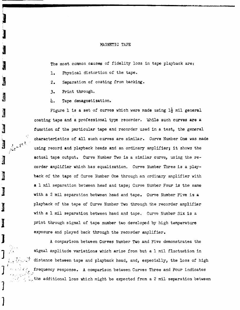

J J
tape and head
J J
In a professional type recorder contact between tape and head
is maintained by the components of tape tension in the head direction
J
Contact is lost by such things as (1) longitudinal waves in the tape in-
J duced by variations in this tension caused by differences in tape adhesion
11J1ir l
I
lt at supply reel or frictional characteristics of the tape as it slides I~middot
across the heads (2) permanent curvature of the tape caused by creep of
J L-
the tape while on the supply reel (3~cupping of the tape caused by difshyl)
ferential dimensional change s between coating and backing tgt4) fluting
] of the edges induced by storage of poorly wound tape (5) wrinkling or 1
] warping of the tape caused by creep of the tape while stored An addishy
tional fidelity loss is occasioned by frequency shifts due to stretching
or shrinking of the tape] Physical distortion of the tape results from the nature of the mashy
] terial itself from the way it is stored and the environment it is
stored in The material itself has molecular configurational strains]
from the manufacturing process is visco-elastic and is a laminate I
] I
]gt1 ~~ It is stored on a reel under tension often poorly wound and the reel
has a lslotted-hub and is often plastic The environment can provide temshy ~
] perature and humidity variations which can induce high stresses in the
tape]
The storage reel is the first source of tape distortion While the
metal MARTE 10 reel seems to be quite good libraries often use the smallshy] er plastic reels ~The smaller radius of curvature at the hub increases
] both the amount of tape curvature resulting from creep and the effect of
the hub slot which causes a localized distortion of the tape) An additional
J II
2
J
fault of plastic reels is flange w~hlliLwhich often is serious enough to
damage edges of the tape both in storage and playback It is recommended
that tapes to be stored for over ten years be stored on1y on the ~ NARTB
metal reel It would also be preferable to use an unslotted hUb even for
this reel Warped reels should be discarded~
The next source of tape distortion is in winding A commonly used
winding tension is seven ounces at the hub of ten and seven inch reels
and five ounces at the hub of five inch reels This is a fairly high
initial stress for plastic films and any unevenness in winding especial
ly in the presence of additional thermal or humidity induced stress~ reshy
sults in edge fluting wrinkling or warping of the tape Tape tension
must be a compromise between a loose wind which permits IIspiderwebbingll
and cupping and a tight wind which causes excessive dimensional changes
Excessive tension increases physical distortion tape sticking and print
through At present seven ounces seems excessive for the seven inch
reel and perhaps somewhat high for the ten inch reel Some tape manu=
facturers use a winding curve which is a compromise between constant
torque and constant tension the tensionysed by manufacturers seem tot (
be excessive for tape storage purposes bull n~p~s should be rewdeg1l~~~Il__~_~ fJYY special device before storage instea~~f ~ing t~~~~- from the tape ~eck tgt tt(-
and tolbull))2~ ~- (1---- shy ~--
The final sources of tape distortion are fluctuations in temperashy
ture and humidity unequal dimensional changes between coating and back~
ing and relaxation of internal stresses In order to avoid these
effects storage at constant temperature and humidity is requiredo Reshy
commended procedure is to condition a tape for 24 hours in an environment
3
) ~ l
I ~
I 1 I 11
n n I I 1 ]
t
~
]
]
of 70 t 5degF and 50 plusmn 10 RH and then to seal it in a can or a plastic
bag impervious to moisture The container should t hen be kept is an enshy
vironment of 70 plusmn 5degF and 50 plusmn 10 RH ~---Some coatingsse~m-to be fungi nutrient some are plasticized
some become tacky in the presence of excess moisture or high temperature
and all of them seem to be somewhat pressure sensitive Despite our efshy
forts to obtain coating fonnulations to date we have been unsuccessful
in doing so because they are closely guarded trade secretso We know
nothing of modern coatings except that some manufacturers say that their
coatings are superior to those of other manufacturers Permafilm is exshy
perimenting with a protective coating for the tape coating one manufacturshy
er makes a laminate instrumentation tape with the coating sandwiched beshy
tween backing material but at present all we can recommend is fungi
inhibition and the use of low temperature low humidity and low stress
together with the use of the coating which has the best rating in the
accelerated aging tests
The next two figures show some of the characteristics of print
through Most important perhaps is that it follows reaction laws and
is an asrmptotic function Its maximum value is a function of the
strength of the master signal distance from master Signal temperatureraquo
stress and external magnetic fields Print through can be kept below
noise level by control of these parameters Frequent rew~nding does seem
to be a good idea as far print through goes for extremely long t~le storage
because while it does not reduce the print through appreciably it does
change its identity from an audible signal to noise Selective erasure
is not recommended for library use because of loss of high freqlency signal
4
]
~ ~
Figure 4 shows the first time erasure characteristics of a printed signal
and a biased signal which permits a decrease of print through to master~ signal ratio Further erasure is a function of the logarithm of the numshy
t ber of erasures with respect to the master signal with the first time
value of eralure with respect to newt print through Unfortunately each
~ f frequency r~quires a different erase current for proper selective erasure
10 that high frequencies are attenuated too much with the current required
for erasure of middle frequency print through For tapes which do not
J OOTOr a wid range of frequencies selective erasure i a good emergency
t treatment prior to re-recording for preservation of the transcriptions
Tape demagnetization under excellent storage conditions is insig= ii )~~I ktr~ ~iCampntJ the maximwn nsasurable amrunt being in the order of I to 2 db
I (r~pound at the higher frequencies for very long storage times At elevated tomshy
middotperatures (above 90~) or in the presence of external magnetic fields ozw ~
rrit poeatar than~u~ it begins to be measureable Demagnetization obeys
bulllaquorv f ~ 88Ile diffusion laws as does print througho
I To ~8rize these remarks on tape
~ Small hub or plastic reels should not be used o A 10 metal
I with an unslotted hub is recommended
2 rrTa O~~d be ~ew~u~d on~~~ special winding device beforeJ s ct~~ - t~-( J(r J shy
i Tapes should be conditioned to 70 t 50F and 50 t 10 RH for
and then sealed in a containero (r-igtl tiJDgtll[ (] This container should be kept in a room at 70 z 50F and
~H stored on edge on stelves made of wod or non-magnetized] lous tapes could be condi tioned t~50--50middotfnd stored at this
~-~--j
5
)
reconditioned to 700F before playback this would
bull external magnetic fields in the storage area should
fields should never exceed 10 gauss
a potential storage life of only
of the rapid rate of chemical degradation The
plastic materials used in tape manufacture have exshy~-
times that value IT perh~ft(~~~ One
he knows more of thEfcoat1ne formulation
increase in longevity changes the probable
ty from degradation of the material to physical
Fidelity loss from these sources can I A 1_ 7
-~ ( fl) t( ) 7~ l~ _ --~~
Proper storage technique and environment (f-- - ~ A( 4 ) A I jJ r
k -
( cct(
6
--
20
o
-20
-40
-60
Recorder Noise Level
Frequency (cps)
1 Actual Tape Output - Constant Power Input
2 Recorder Output - Equalization
3 Actual Tape Output - Tape 1 mil from Head
4 Actual Tape Output - Tape 2 mil from Head
5 Recorder Output - Tape 1 mil from Head
6 Print Through (Estimated 20 year level)
Characteristic Data for a General Coated~ 15 Mil Tape Showing the Interrelationship of
Various Parameters (Actual Values Depend on Tape and Recorder)
FIGURE 1
---____
0
j~ -2 II 0 E-tllE-t +gt Q+gt -4
Q ~
6 Ii- -60 ~sectr-I (l) C1I 1gt1 s+gt -8
fJl
~~ ~ +gt -10C1I 0r-I+gt ~
-12 0 1 2 3
Number of Layers Between Master and Slave
-50
r-I
~ ttO
()
0 +gt 0 ttO J
II 0
E-i
+gt Q
-55~ sect
-57 o 1 Week
Time
initial intensity
------+----------------- - -1 - -i
intensity after separation
---1---t i
Typical Print Through Curve Ambient Temperature 1000 cps 15 ips
I mil General Coating Tape
FIGURE 2
6 1 I Il_
I I I -Jshy
___ - I I
I--~
P 1-
i_
~0 shy
I I- i 1
~ o I-- ~~~1
I I 1 I
I
~-
f-shy
T
70 100 150 Temperature of
Print Through as a Function of Temperature 75 ips 400 cps 3 Total Distortion
(Audio Devices)
sect
40 0
M +
~ c tW 0
~50 +
s oM
Jt 0
+ -60m s bD
M to 65
1 day 1 week 1 month 1 year 10 years 100 years
Time of Contact (Audio Devices)
FIGURE 3
vu o
i I I I I i ~ I ~
1---- -~----- ---- 2 - --
I iI Signal -- ----+-------i - -- -
- 4 _ ~_P~6 cps _~_ -~ middotmiddot~~rk ~-- _1 - 6
Print Through 1- 8 --- 1----+-shy- ~
1- -- --- -----i--- -- c-- -- - - shy -----1--shy-10
~ ___ I ___ ____ ___ _ ___ _ ~_ _ -12
-14 I----~--- -r--l-~-~ I I
-16 ---+---c- -- - - ------l----I-I--~
Selective Erasure Graph I-18 - l+----e---
-20 I I _---JL-_JJL--__
Increasing Erase Current
FIGURE 4