Embed Size (px)
Citation preview
© 2020 JETIR June 2020, Volume 7, Issue 6 www.jetir.org (ISSN-2349-5162)
JETIR2006250 Journal of Emerging Technologies and Innovative Research (JETIR) www.jetir.org 1711
Review of Wing Rib Design and Analysis of
Aircraft
1Rohit Kumar, 2Syed Mohsin, 3Ravindra Jaikishan Singh
1Assistant Professor, 2Assistant Professor, 3Student
1Aeronautical Department,
1MVJ College of Engineering. Near ITPB, Whitefield, Bangalore, India.
Abstract:
Ribs are essential component of Aircraft wing. Ribs are used for maintaining aerofoil contour shape of
the wing and reduce stress acting on it. The paper focuses determine stress on wing rib with different
designs and select the appropriate design. SOLIDWORKS is used for designing and estimating physical
properties of design while ANSYS STATIC STRUCTURAL is used for analysis. Conclusion of the wing
rib design is done after study of 5 different rib designs.
Keywords: SOLIDWORKS, ANSYS, Contour, stress, wing rib.
Introduction:
Ribs are the structural element which combine with spars and stringers to form wing. They usually
maintain the structure from leading edge to trailing edge of the aircraft wing. It also help wing to maintain
cambered shape and reduce load acting on the skin by transmitting it to spars. Ribs reduce the effect of
stress acting on wing.
Wing ribs are generally made up with wood or metal. Same kind of material can be used in spars and ribs,
expect metal ribs can be used with wooden spar arrangement. The design of the ribs can vary based on the
requirement. In our paper we are mainly discussing about stress developed on wing rib design of the wing.
Material and Design selection
As ribs can be made with either wood or metal therefore we have selected Al alloy cast 713 material for
our study. Al alloy cast 713 consisting of 0.25% silicon, 0.35% chromium, 0.15% nickel, 1.1% iron, 0.4 to
1% copper, 0.2 to 0.5% magnesium, 0.25% titanium, 7 to 8% zinc, and 0.6% manganese. For design criteria
we have studied hole, strip and truss arrangement in ribs.
Design:
The modeling of the rib is done in solidworks
© 2020 JETIR June 2020, Volume 7, Issue 6 www.jetir.org (ISSN-2349-5162)
JETIR2006250 Journal of Emerging Technologies and Innovative Research (JETIR) www.jetir.org 1712
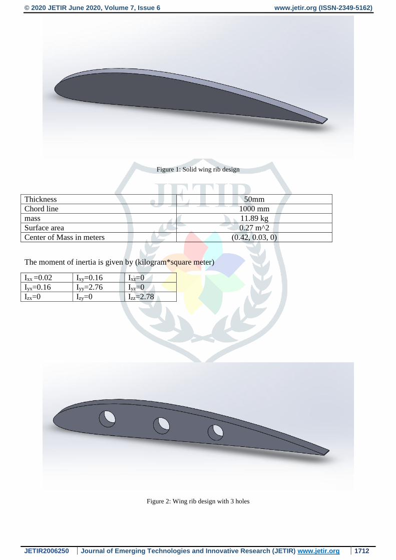
Figure 1: Solid wing rib design
Thickness 50mm
Chord line 1000 mm
mass 11.89 kg
Surface area 0.27 m^2
Center of Mass in meters (0.42, 0.03, 0)
The moment of inertia is given by (kilogram*square meter)
Ixx =0.02 Ixy=0.16 Ixz=0
Iyx=0.16 Iyy=2.76 Iyz=0
Izx=0 Izy=0 Izz=2.78
Figure 2: Wing rib design with 3 holes

© 2020 JETIR June 2020, Volume 7, Issue 6 www.jetir.org (ISSN-2349-5162)
JETIR2006250 Journal of Emerging Technologies and Innovative Research (JETIR) www.jetir.org 1713
Hole diameter 60mm
Distance between each holes 200mm
mass 10.71 kg
Surface area 0.28 m^2
Center of mass (in meter) (0.42,0.03,0)
The moment of inertia is given by (kilogram*square meter)
Ixx =0.02 Ixy=0.14 Ixz=0
Iyx=0.14 Iyy=2.54 Iyz=0
Izx=0 Izy=0 Izz=2.56
Figure 3: Wing rib design with 2 holes
Dimensions for 2 holes rib
Hole diameter 60mm
Distance between each holes 200mm
mass 11.08 kg
Surface area 0.28 m^2
Center of mass (in meter) (0.43,0.03,0)
The moment of inertia is given by (kilogram*square meter)
Ixx =0.02 Ixy=0.15 Ixz=0
Iyx=0.15 Iyy=2.68 Iyz=0
Izx=0 Izy=0 Izz=2.7

© 2020 JETIR June 2020, Volume 7, Issue 6 www.jetir.org (ISSN-2349-5162)
JETIR2006250 Journal of Emerging Technologies and Innovative Research (JETIR) www.jetir.org 1714
Figure 4: Wing rib design with vertical strips
Airfoil Thickness 50mm
Vertical truss thickness 2mm
mass 9.68 kg
Surface area 0.39
Center of mass(meter) (0.5,0.03,0)
The moment of inertia is given by (kilogram*square meter)
Ixx =0.05 Ixy=0.11 Ixz=0
Iyx=0.11 Iyy=3.37 Iyz=0
Izx=0 Izy=0 Izz=3.42
Figure 5: Wing rib design with criss cross
thickness 50mm
Vertical truss thickness 2mm
Inclined trusss thickness 5mm
mass 10.6 kg
Center of mass (meter) (0.5,0.03,0)

© 2020 JETIR June 2020, Volume 7, Issue 6 www.jetir.org (ISSN-2349-5162)
JETIR2006250 Journal of Emerging Technologies and Innovative Research (JETIR) www.jetir.org 1715
The moment of inertia is given by (Kg.m2)
Ixx =0.05 Ixy=0.12 Ixz=0
Iyx=0.12 Iyy=3.46 Iyz=0
Izx=0 Izy=0 Izz=3.52
Meshing:
Meshing is a crucial step for analysis of any structure or body ,the process of discretization of any body or
domain into small domain for solving the governing equation used for analysis of a given system for our
analysis an unstructured mesh with triangular topology is used for discretization and the software used is
Ansys meshing the details of the mesh is tabulated below
No. of elements 31656
No. of nodes 51751
Element size 1.4876e-2
Mesh topology triangular
Analysis:
The analysis is done in ansys workbench 2019 R2 the pressure applied is 100pa
Figure 6: Analysis of solid wing rib design

© 2020 JETIR June 2020, Volume 7, Issue 6 www.jetir.org (ISSN-2349-5162)
JETIR2006250 Journal of Emerging Technologies and Innovative Research (JETIR) www.jetir.org 1716
Figure 7: Analysis of Wing rib design with 3 holes
Figure 8: Analysis of Wing rib design with 2 holes

© 2020 JETIR June 2020, Volume 7, Issue 6 www.jetir.org (ISSN-2349-5162)
JETIR2006250 Journal of Emerging Technologies and Innovative Research (JETIR) www.jetir.org 1717
Figure 9: Analysis of Wing rib design with vertical strips
Figure 10: Analysis of Wing rib design with criss cross
Type Mass (Kg) Min. Stress (Pa) Max. Stress (Pa)
Solid Rib 11.89 4.98 365.3
Rib with 3 holes 10.71 5.975 356.88
Rib with 2 holes 11.08 5.946 382.99
Rib with vertical
Strips
9.68 0.1476 210.9
Ribs with criss
cross
10.6 0.1626 210.55
© 2020 JETIR June 2020, Volume 7, Issue 6 www.jetir.org (ISSN-2349-5162)
JETIR2006250 Journal of Emerging Technologies and Innovative Research (JETIR) www.jetir.org 1718
Conclusion:
From the study of above design and analysis Rib with vertical Strips and criss cross is experiencing less
stress compare to other design. Ribs with criss cross may have developed less stress but compare to vertical
strips it may not be that effective due to more mass and less space which can be used for storing more fuel
etc. So, we can conclude that ribs with vertical strips is having better performance than other designs
mentioned above.
Reference:
[1] Wing Rib Stress Analysis and Design Optimization Using Constrained Natural Element Method,
Amine Bennaceur, Mohamed;Xu, Yuan-ming;Layachi, Hemza.IOP Conference Series: Materials
Science and Engineering, Volume 234, Issue 1, pp. 012018 (2017)
[2] Optimal design of aircraft wing structures: a computer aided design method J. Ampofo ; F.
Ferguson, Proceedings of the 5th Biannual World Automation Congress
[3] Grossman, R. Hafika et al., "Integrated Aerodynamic-Structural Design of a Transport Wing", Journal
of Aircraft, vol. 27, no. 12, pp. 1050-1056, 1990.
[4] D P. Raymer, Aircraft Design: A Conceptual Approach, 1992.
[5] Analysis of wing flexure deformation based on ANSYS, Xueyan Zhang ; Yan Zhao ; Fan Si, 2018
IEEE/ION Position, Location and Navigation Symposium (PLANS)
[6] Optimization of Structural Topology, Shape and Material’, M P Bendsøe, Springer-Verlag, Heidelberg,
Germany, 1995.
[7] Zheng Yang *, Chang-Boo Kim, Chongdu Cho, HyeonGyuBeom “The concentration of stress and
strain in finite thickness elastic plate containing a circular hole”, International Journal of Solids and
Structures Vol. 45,Pg. 713- 731(2008)
[8] Design And Stress Analysis of Aircraft Wing Rib With Various Cut Outs by S. Bairavi, Mr. Suresh
balaji, INDIAN JOURNAL OF APPLIED RESEARCH Volume : 6 Issue : 4 April 2016 ISSN -
2249-555X
[9] Bindu H.C, Muhammad Muhsin Ali.H “Design and Analysis of a Typical wing Rib for Passenger
Aircraft” International Journal of Innovative Research in Science, Engineering and Technology. Vol.2,
Issue 4, (2013).

© 2020 JETIR June 2020, Volume 7, Issue 6 www.jetir.org (ISSN-2349-5162)
JETIR2006250 Journal of Emerging Technologies and Innovative Research (JETIR) www.jetir.org 1719
[10] Bindu H.C, Muhammad MuhsinAli.H “Design and Analysis of a Typical wing Rib for Passenger
Aircraft” International Journal of Innovative Research in Science, Engineering and Technology. Vol.2,
Issue 4, (2013).
[11] Optimization of Structural Topology, Shape and Material’, M P Bendsøe, Springer-Verlag,
Heidelberg, Germany, 1995.
[12] Zheng Yang *, Chang-Boo Kim, Chongdu Cho, HyeonGyuBeom “The concentration of stress and
strain in finite thickness elastic plate containing a circular hole”, International Journal of Solids and
Structures Vol. 45,Pg. 713- 731(2008)