Embed Size (px)
Citation preview

Technical Track www.odva.org
Review of the CIP Safety SafeMotion Profile Functionality
Mark Chaffee Rockwell Automation
John Deinlein Rockwell Automation

Technical Track 2014 Industry Conference & 16th Annual Meeting page 2 © 2014 ODVA, Inc. All rights reserved. www.odva.org
Safety Controller Architecture
Networked Safety Based on EtherNet/IP Safety Controller/PLC
• Safety Task
Safety I/O Devices • Emergency Stop • Safety Relays • Light Curtains • Safety Mats • Door Lock Control
New Safety Device CIP Safety Drives
Technical Track 2014 Industry Conference & 16th Annual Meeting page 3 © 2014 ODVA, Inc. All rights reserved. www.odva.org
Safety Standards
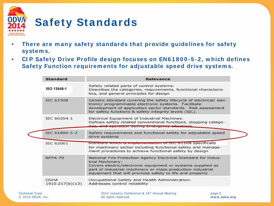
• There are many safety standards that provide guidelines for safety systems.
• CIP Safety Drive Profile design focuses on EN61800-5-2, which defines Safety Function requirements for adjustable speed drive systems.

Technical Track 2014 Industry Conference & 16th Annual Meeting page 4 © 2014 ODVA, Inc. All rights reserved. www.odva.org
EN61800-5-2 Drive Safety Functions
Functionality Grouping • Disconnect Torque generating power to the motor (STO)
• Safe stop (i.e. SS1, SS2) • Safe speed monitoring (i.e. SSM) • Safe acceleration monitoring (i.e. SLA) • Safe torque monitoring (i.e. SLT) • Safe position monitoring (i.e. SLP) • Safe brake control (i.e. SBC)
• EN61800-5-2 provides high level functional description of drive safety functions
• These are the safety functions that are targeted for CIP Safety Drive Profile support

Technical Track 2014 Industry Conference & 16th Annual Meeting page 5 © 2014 ODVA, Inc. All rights reserved. www.odva.org
Drive Safety Function Examples
STO (Safe Torque Off) • Stop Request • Wait Stop Delay • Disable Motor Power
SS1 (Safe Stop 1) • Stop Request • Wait Stop Monitoring Delay • Monitor Decel Until Standstill • Disable Motor Power
SLS (Safe Limited Speed) • Safe Limited Speed Request • Wait Stop Monitoring Delay • Monitor Speed < Safe Speed Limit

Technical Track 2014 Industry Conference & 16th Annual Meeting page 6 © 2014 ODVA, Inc. All rights reserved. www.odva.org
Typical Drive Safety Core
Control Board .
PHY#2
NANDFlashEMIF_A
PHY#1MII
MII
KMCLFPGA
Three Port
Switch
Encoder Interface
Local Display Interface
Feedback ConnectorMidrange Drive Enclosure
Micro Controller
CH0
Micro Controller
CH1
Pow
er B
oard
Inte
rfac
eC
onne
ctor
Power – Control Interface
SUP
Safety Disable
DDR2Memory
Drive Core (Host)
Comms Core Control
CoreSharedRAM
Safety Core
Power Processor
PWMS
Power Board
ENET Port 1
Connector
ENET Port 2
ConnectorVoltage
Regulators
RM
II
ANALOG CURRENT/VOLTAGE

Technical Track 2014 Industry Conference & 16th Annual Meeting page 7 © 2014 ODVA, Inc. All rights reserved. www.odva.org
Drive Safety System Architecture Options
OPTION 1 Drive safety I/O activated drive safety functions
OPTION 2 Safety controller activated drive safety functions
OPTION 3 Safety controller configured & activated drive safety functions
OPTION 4 Safety controller executed drive safety functions
Safe Motion Subcommittee Target
Safe Motion Subcommittee Target
Technical Track 2014 Industry Conference & 16th Annual Meeting page 8 © 2014 ODVA, Inc. All rights reserved. www.odva.org
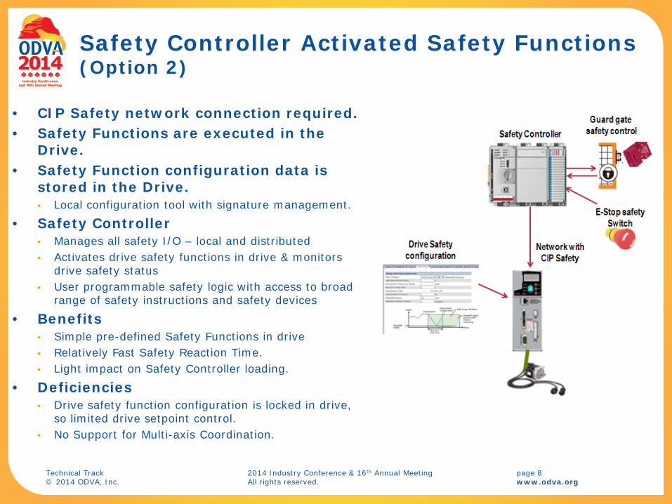
Safety Controller Activated Safety Functions (Option 2)
• CIP Safety network connection required. • Safety Functions are executed in the
Drive. • Safety Function configuration data is
stored in the Drive. • Local configuration tool with signature management.
• Safety Controller • Manages all safety I/O – local and distributed • Activates drive safety functions in drive & monitors
drive safety status • User programmable safety logic with access to broad
range of safety instructions and safety devices
• Benefits • Simple pre-defined Safety Functions in drive • Relatively Fast Safety Reaction Time. • Light impact on Safety Controller loading.
• Deficiencies • Drive safety function configuration is locked in drive,
so limited drive setpoint control. • No Support for Multi-axis Coordination.
Technical Track 2014 Industry Conference & 16th Annual Meeting page 9 © 2014 ODVA, Inc. All rights reserved. www.odva.org
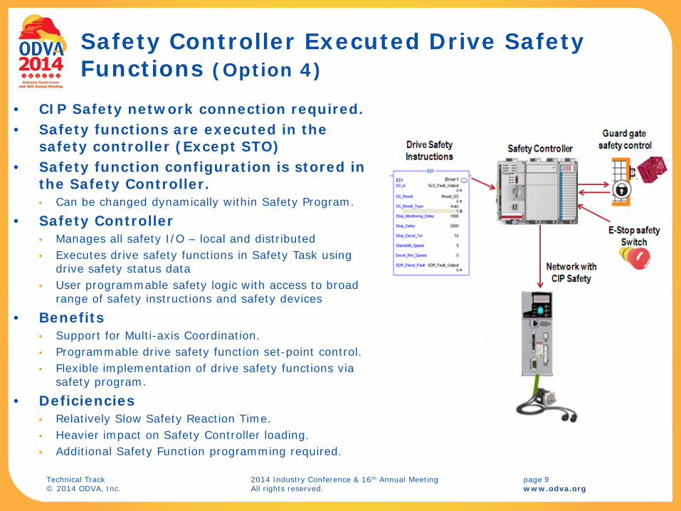
Safety Controller Executed Drive Safety Functions (Option 4)
• CIP Safety network connection required. • Safety functions are executed in the
safety controller (Except STO) • Safety function configuration is stored in
the Safety Controller. • Can be changed dynamically within Safety Program.
• Safety Controller • Manages all safety I/O – local and distributed • Executes drive safety functions in Safety Task using
drive safety status data • User programmable safety logic with access to broad
range of safety instructions and safety devices
• Benefits • Support for Multi-axis Coordination. • Programmable drive safety function set-point control. • Flexible implementation of drive safety functions via
safety program.
• Deficiencies • Relatively Slow Safety Reaction Time. • Heavier impact on Safety Controller loading. • Additional Safety Function programming required.

Technical Track 2014 Industry Conference & 16th Annual Meeting page 10 © 2014 ODVA, Inc. All rights reserved. www.odva.org
Safety Motion Device Profile
New Profile Targets 2 Distinct Drive Types • CIP Motion Drives • Non-CIP Drives (SERCOS III)
Profile Adds 2 New Safety Drive Device Types • CIP Motion Safety Drive Device Type: 2Dhex
• Safety Drive Device Type: 2Ehex
Both Drive Device Types… • Support CIP Safety Connections to Safety Controller. • Share Common Safe Motion Objects. • Share Common Safety I/O Assembly Definitions. • Share Common Safety Supervisor State Model

Technical Track 2014 Industry Conference & 16th Annual Meeting page 11 © 2014 ODVA, Inc. All rights reserved. www.odva.org
Object Model for CIP Motion Safety Drive Device
New Safe Motion Objects: 1. Safety Stop Functions Object 2. Safety Limit Functions Object 3. Safety Feedback Object 4. Safety Dual Channel Feedback Object
Basic CIP Safety Objects: 1. Safety Validator Object 2. Safety I/O Assembly Object 3. Safety Supervisor Object
CIP Motion Objects: 1. Motion Device Axis Object 2. Time Sync Object 3. QoS Object
Basic CIP Objects: 1. Identity Object 2. Message Router optional required
SafetyIO
SafetyIO
SafetyI/O
Connection Manager orConnection Object
CIP Network
QoSObject*
Message Router
SafetySupervisor
Link SpecificObject
SafetyIO
SafetyIO
Motion I/O
SafetyIO
SafetyIO
SafetyValidators
SafetyIO
SafetyIO
Motion Device Axis Object*
Time Sync Object*
SafetyIO
SafetyIO
ExplicitMessage
SafetyIO
SafetyIO
Safety Dual Channel
Feedback
SafetyIO
SafetyIO
Safety Feedback
SafetyIO
SafetyIO
Safety Limit Functions
+
Message Router
SafetyIO
SafetyIO
Safety Stop Functions
+
IdentityObject
Safety Output Assembly
Safety Input Assembly
* Applicable to CIP Motion Safety Devices
Same Message Router as shown below

Technical Track 2014 Industry Conference & 16th Annual Meeting page 12 © 2014 ODVA, Inc. All rights reserved. www.odva.org
Motion Device Axis Object State Model
CIP Motion Drive behavior is governed by the Motion Device Axis Object State Model.
Axis Object states are mapped to Identity Object states.
Identity Object states govern Module Status LED Behavior.
Stopping
MajorFaulted
Aborting
Starting
Initializing
Drive Disable Major Fault
Fault Reset
Drive Enable or Test
Transient State
Terminal State
Shutdown
Stopped
Shutdown Reset
Running
Testing
Pre-Charge
StartInhibited
Shutdown
Off
Initialization Fault
Inhibits Cleared
Inhibits Present
Major Fault
Enabled Operation
Disabled Operation
InitializationComplete
Self Test
Shutdown
Standby Faulted
Standby
Fault Reset
Major Fault
Major Fault
Fault ResetStandby
Bus Up!Bus Up

Technical Track 2014 Industry Conference & 16th Annual Meeting page 13 © 2014 ODVA, Inc. All rights reserved. www.odva.org
Safety Supervisor State Model
CIP Safety Device behavior is governed by the Safety Supervisor State Model.
Safety Supervisor states are mapped to Identity Object states.
Safety Supervisor states govern Module Status LED Behavior.
Problem: A CIP Motion Safety Drive has only 1 Identity Object and 1 Module Status LED. How do we reconcile behavior?

Technical Track 2014 Industry Conference & 16th Annual Meeting page 14 © 2014 ODVA, Inc. All rights reserved. www.odva.org
Safety Drive State Precedence
Identity state and Module Status LED behavior can be reconciled by applying state precedence rules to determine the drive’s Governing State: 1. Self-Test 2. Unrecoverable Fault 3. Recoverable Fault 4. Safety Configuring 5. Safety Idle 6. Axis Standby 7. Axis Operational 8. Safety Executing 9. Safety Waiting for TUNID (Out of Box)

Technical Track 2014 Industry Conference & 16th Annual Meeting page 15 © 2014 ODVA, Inc. All rights reserved. www.odva.org
Safety Drive State Mapping Safety State Axis State Governing State Identity State Module Status LED
Self-Testing Any State Safety Supervisor Device Self-Testing Flashing Red/Green Any State* Self-Test Motion Axis Device Self-Testing Flashing Red/Green Self-Test Exception Any State* Safety Supervisor Major Unrecoverable Solid Red Waiting for TUNID Any State* Safety Supervisor Standby Flashing Red/Green Configuring Any State* Safety Supervisor Standby Flashing Red/Green Idle Any State* Motion Axis Standby Flashing Green
Waiting for TUNID with Torque Permitted, Executing, Executing with Torque Permitted
Initializing Pre-Charge Shutdown Start Inhibit
Motion Axis Standby Flashing Green
Stopped Stopping Starting Running Testing
Motion Axis Operational Solid Green
Any State* Aborting Motion Axis Major Recoverable or Major Unrecoverable
Flashing Red or Solid Red
Any State* Major Faulted Motion Axis Major Recoverable or Major Unrecoverable
Flashing Red or Solid Red
Abort Any State* Safety Supervisor Major Recoverable Flashing Red Critical Fault Any State* Safety Supervisor Major Unrecoverable Solid Red

Technical Track 2014 Industry Conference & 16th Annual Meeting page 16 © 2014 ODVA, Inc. All rights reserved. www.odva.org
New Safety Supervisor States for
Commissioning & Maintenance Unlike Safety I/O devices,
Safety Drives are sophisticated devices that require commissioning and maintenance.
Commissioning requires the safety drive be operational “Out of the Box” when there is no Safety Configuration. • Add “Waiting for TUNID with
Torque Permitted state”.
Maintenance requires the safety drive be permitted to operate when the Safety Output Connection is Idle. • Add “Executing with Torque
Permitted state”.
Technical Track 2014 Industry Conference & 16th Annual Meeting page 17 © 2014 ODVA, Inc. All rights reserved. www.odva.org
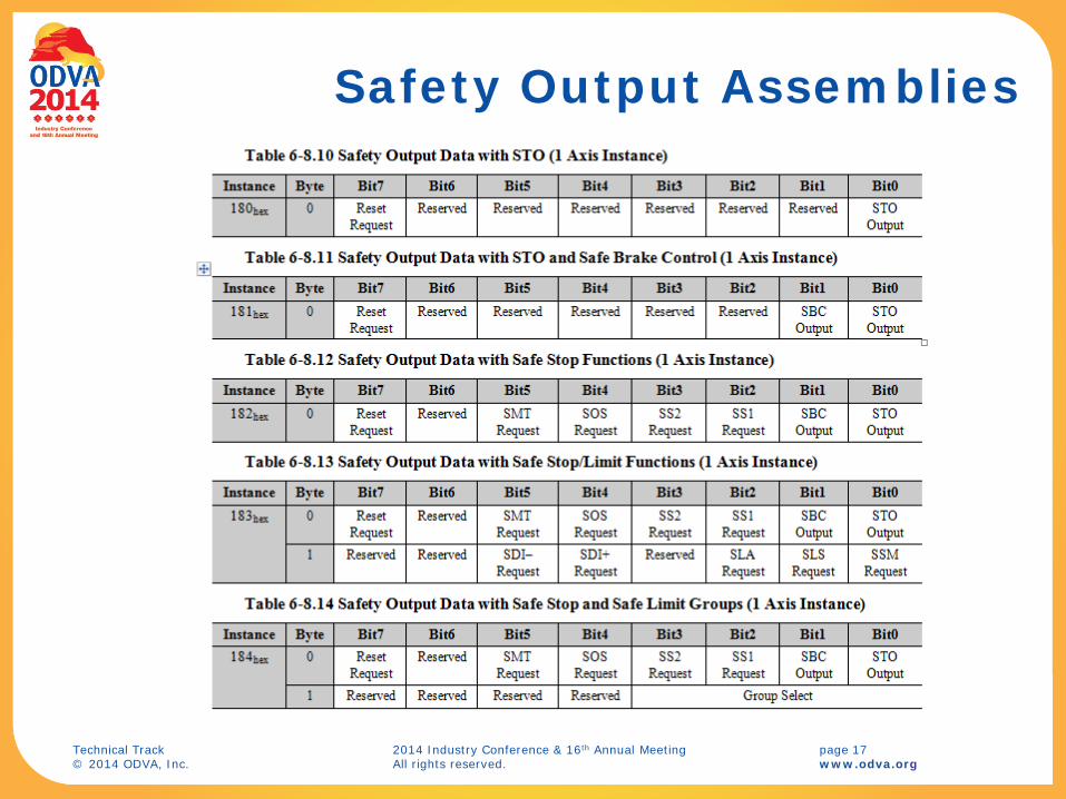
Safety Output Assemblies

Technical Track 2014 Industry Conference & 16th Annual Meeting page 18 © 2014 ODVA, Inc. All rights reserved. www.odva.org
Safety Input Assemblies

Technical Track 2014 Industry Conference & 16th Annual Meeting page 19 © 2014 ODVA, Inc. All rights reserved. www.odva.org
Safety Input Assembly with Feedback Data

Technical Track 2014 Industry Conference & 16th Annual Meeting page 20 © 2014 ODVA, Inc. All rights reserved. www.odva.org
Safety Input Assemblies with 2 Axis Instances

Technical Track 2014 Industry Conference & 16th Annual Meeting page 21 © 2014 ODVA, Inc. All rights reserved. www.odva.org
Safety Function Object Interaction
Safety Feedback
Safety Dual Channel
Feedback
Safety Limit Functions Safety Stop Functions
Enc.
Brake
Output Assembly
SS1 Request
STO Output
SBC Output
SLS Request
Safe Stop 1
Safety Feedback
Enc.
SS1 Complete
STO Status
Safe Brake Control
Safe Torque Off
Safely-Limited Speed
Input Assembly
SS1 Active
Torque Disabled
Brake Engaged
SLS Active DriveStop
Safety Fault
Reset Request
DriveEnable
Feedback Velocity
Safety Limit Active
STO
Technical Track 2014 Industry Conference & 16th Annual Meeting page 22 © 2014 ODVA, Inc. All rights reserved. www.odva.org
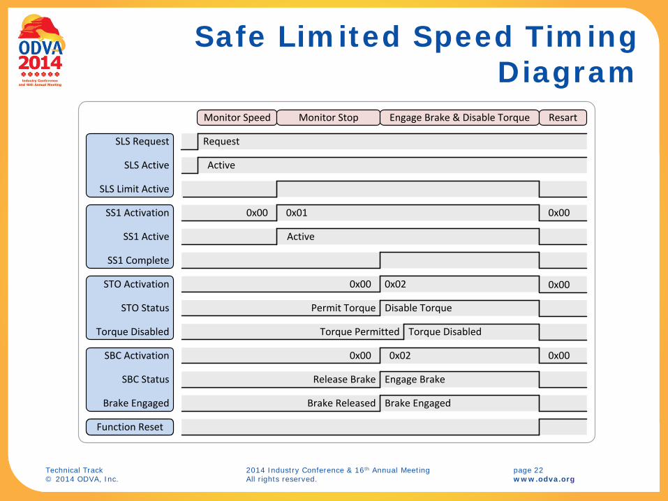
Safe Limited Speed Timing Diagram
SLS Request
SLS Active
SLS Limit Active
Request
Active
SBC Status
Brake Engaged
Engage Brake
SS1 Active
SS1 Activation
STO Status Disable Torque
STO Activation
0x00
Torque Disabled Torque Disabled
0x01
0x00 0x02
0x00
SBC Activation 0x00 0x02
Function Reset
Release Brake
Brake Released Brake Engaged
0x00
Permit Torque
Torque Permitted
0x00
Active
SS1 Complete
Monitor Speed Monitor Stop Engage Brake & Disable Torque Resart

Technical Track 2014 Industry Conference & 16th Annual Meeting page 23 © 2014 ODVA, Inc. All rights reserved. www.odva.org
Group Safety Limit Function Selection
Instance
Byte Bit7 Bit6 Bit5 Bit4 Bit3 Bit2 Bit1 Bit0
184hex 0 Reset Request
Reserved SMT Request
SOS Request
SS2 Request
SS1 Request
SBC Output
STO Output
1 Reserved Reserved Reserved Reserved Group Select
4 to 16Decoder
0
SLS RequestSDI Positive RequestSDI Negitive RequestSSM Request
SLA RequestSelect SLA
Select SDI PosSelect SDI Neg
Select SLS
Function Select(22)
Select SSM
Instance 11
Instances 2-152-15
Group Select
Group Active

Technical Track 2014 Industry Conference & 16th Annual Meeting page 24 © 2014 ODVA, Inc. All rights reserved. www.odva.org
Accessing Safety Status Data

Technical Track 2014 Industry Conference & 16th Annual Meeting page 25 © 2014 ODVA, Inc. All rights reserved. www.odva.org
Conclusion
Drives with network safety connection support are a key component in emerging safety controller based safety architectures.
Recently published Safety Motion Device Profile addresses critical need for a networked “Safety Drive”.
Two new safety drive device types were defined, one serving CIP Motion drives and one for non-CIP (SERCOS III) drives.
Merging existing CIP Motion behavior with CIP Safety behavior created design challenges with respect to state behavior, commissioning, and maintenance.
Safety Motion Device I/O assemblies and new Safety Motion Objects were the reviewed.
Finally, mechanisms to coordinate motion control functions with drive safety functions were discussed, introducing the concept of Safety Status Pass Thru.