Embed Size (px)
Citation preview

C-A/AP/#151 April 2004
Review of Options for the SCL for the AGS Upgrade
Alessandro G. Ruggiero
Collider-Accelerator Department Brookhaven National Laboratory
Upton, NY 11973
1.5-GeVBooster
200-MeVTDL
28-GeV AGS
HI Tandem
Figure 1. The AGS Accelerator Complex
Review of Options for the SCL for the AGS Upgrade*
Alessandro G. Ruggiero
Brookhaven National LaboratoryApril 25, 2004
Summary
In this technical report we review options for the design of a 1.2-1.5 GeV Super-Conducting Linac (SCL) for the AGS Upgrade program toward a proton average beampower of 1 MWatt. At the present the only high-power proton SCL we can makereference to is the SCL of the SNS project. It is directly from this that we extrapolate hereperformance and cost for our study.
Present AGS Performance
With a typical mode of operation the present AGS accelerator facility can providean average proton beam power of about 100 kW at the kinetic energy of 28 GeV. Thelayout of the accelerator complex is shown in Figure 1, and the ordinary proton cycle inFigure 2. Negative hydrogen ions (H–) are generated by a 35-keV ions source, focused,bunched and pre-accelerated in a 750-keV RFQ, and finally accelerated to 200 MeV inthe following Drift-Tube Linac (DTL). The beam is then transferred into the 1.5-GeVBooster that has a circumference of about a quarter of that of the AGS. Multi-turninjection into the Booster is done with the method of charge exchange. The Booster canaccelerate at the repetition rate of 7.5 Hz. Since four Booster cycles are required for acomplete fill of the AGS, about half second is spent for acceleration of the four pulses inthe Booster. Once injection into the AGS is completed, the beam is finally accelerated to28 GeV in about one second. The overall cycle may take up to three seconds, or more,
depending on the presence of a high-energy flat top for slow spill extraction.The Booster acceleration period is thus anappreciable fraction of that of the overallAGS cycle. Heavy-Ions are accelerated ina similar fashion. They are generated bythe HI Tandem, accelerated first in theBooster to a final energy that depends onthe charge state and mass of the ion,transferred and accelerated to the AGSwhere, for instance, for Gold (Au) thefinal energy is about 12 GeV/u.
* Work performed under the auspices of the Department of Energy of United States
2
Figure 3. AGS Cycle with 1.2-GeV SCL
0.4 sec
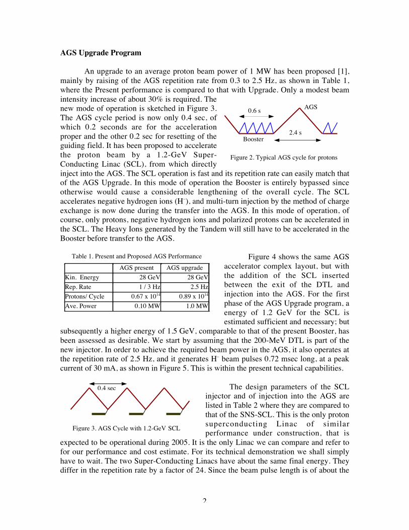
AGS Upgrade Program
An upgrade to an average proton beam power of 1 MW has been proposed [1],mainly by raising of the AGS repetition rate from 0.3 to 2.5 Hz, as shown in Table 1,where the Present performance is compared to that with Upgrade. Only a modest beamintensity increase of about 30% is required. Thenew mode of operation is sketched in Figure 3.The AGS cycle period is now only 0.4 sec, ofwhich 0.2 seconds are for the accelerationproper and the other 0.2 sec for resetting of theguiding field. It has been proposed to acceleratethe proton beam by a 1.2-GeV Super-Conducting Linac (SCL), from which directlyinject into the AGS. The SCL operation is fast and its repetition rate can easily match thatof the AGS Upgrade. In this mode of operation the Booster is entirely bypassed sinceotherwise would cause a considerable lengthening of the overall cycle. The SCLaccelerates negative hydrogen ions (H–), and multi-turn injection by the method of chargeexchange is now done during the transfer into the AGS. In this mode of operation, ofcourse, only protons, negative hydrogen ions and polarized protons can be accelerated inthe SCL. The Heavy Ions generated by the Tandem will still have to be accelerated in theBooster before transfer to the AGS.
Figure 4 shows the same AGSaccelerator complex layout, but withthe addition of the SCL insertedbetween the exit of the DTL andinjection into the AGS. For the firstphase of the AGS Upgrade program, aenergy of 1.2 GeV for the SCL isestimated sufficient and necessary; but
subsequently a higher energy of 1.5 GeV, comparable to that of the present Booster, hasbeen assessed as desirable. We start by assuming that the 200-MeV DTL is part of thenew injector. In order to achieve the required beam power in the AGS, it also operates atthe repetition rate of 2.5 Hz, and it generates H– beam pulses 0.72 msec long, at a peakcurrent of 30 mA, as shown in Figure 5. This is within the present technical capabilities.
The design parameters of the SCLinjector and of injection into the AGS arelisted in Table 2 where they are compared tothat of the SNS-SCL. This is the only protonsuperconducting Linac of similarperformance under construction, that is
expected to be operational during 2005. It is the only Linac we can compare and refer tofor our performance and cost estimate. For its technical demonstration we shall simplyhave to wait. The two Super-Conducting Linacs have about the same final energy. Theydiffer in the repetition rate by a factor of 24. Since the beam pulse length is of about the
0.6 ssec
2.4 ssec
AGS
Booster
Figure 2. Typical AGS cycle for protons
Table 1. Present and Proposed AGS Performance
AGS present AGS upgradeKin. Energy 28 GeV 28 GeVRep. Rate 1 / 3 Hz 2.5 HzProtons/ Cycle 0.67 x 10¹⁴ 0.89 x 10¹⁴
Ave. Power 0.10 MW 1.0 MW

3
same duration (0.72 versus 1.0 ms), theoverall duty cycle also differ by a factorof 33. As a consequence, though theaverage beam power in the AGS-SCL is afactor 35 lower than that in the SNS-SCL,the peak power values are comparable (25versus 26 MW). But in the last analysis isthe peak beam power figure thatdetermines the design, performance andcost of a Super-Conducting Linac. Thus,apart from some minor differences, theSCL required as the new injector for theAGS upgrade is expected to be verysimilar to that of the SNS project.
The SNS-SCL
The layout of the SNS-SCL [2] isshown in Figure 6. It is 340 m long and is madeof 4 sections. The first section is the roomtemperature 185.6-MeV Linac that in turn ismade of a 2.5-MeV Front-End (FE, ion sourceand RFQ), a 402.25-MHz DTL section foracceleration to 86.8 MeV, and the final CCLsection operating at 805 MHz. The roomtemperature Linac is 99.2 m long and isfollowed by a 2.35-m long matching section.The Super-Conducting Linac proper operates at805 MHz. It is made in turn of three sections:(i) the 64.2-m long Medium-β section foracceleration to 387 MeV; (ii) the 94.7-m longHigh-β section for acceleration to a full 1.0GeV; and (iii) a 71-m long Extra section forfurther acceleration to 1.3 GeV if required inthe future.
The bottom of Figure 6 gives directlength and cost extrapolation of the sameSNS-SCL also operating at either 1.2 or 1.5GeV, rounded off as closely as possible, andthe total cost as derived directly from thedocumentation of the SNS project.According to the same source, the total cost,
including contingency and burden charges, of the SNS-SCL was 310.9 M$ in April 2002,that escalated to 322.5 M$ after a DOE review in October 2003, including also the cost of
1.5-GeVBooster
200-MeVTDL
28-GeV AGS
HI Tandem
Figure 4. AGS Upgrade with 1.2-GeV SCL
1.2-GeV SCL
0.4 sec
1 x 720 µs @ 30 mA
Figure 5. 200-MeV DTL Duty Cycle
Table 2. Comparison of AGS and SNS SCL
(*) Including 5% for controlled beam loss(**) Equivalent to 1 MW @ 28 GeV(+) Including 10% for controlled beam loss
AGS SNSKinetic Energy, GeV 1.2 1.0Repetition Rate, Hz 2.5 60Protons / pulse, 1014 0.95 (*) 1.65Ave. Beam Power, MW 0.045 (**) 1.56 (+)Peak Beam Power, MW 25 26Average Current, mA 0.038 1.56Pulse Length, ms 0.716 1.0Duty Cycle, % 0.18 6.0Linac Ave. Cur., mA 21 26Linac Peak Cur., mA 28 38Chopping Ratio, % 75 68Chopping Freq., MHz 8.01 1.058No. Injected Turns 240 1060

4
the 2.5-MeV Front-End and the Extra section*. To be noticed that, considering the shorterenergy acceleration range, the SNS Medium-β section is relatively longer and moreexpensive than the High-β section (64 versus 95 meter, and about 80 versus 110 M$).
Figure 6. Layout, Dimensions, Performance and Cost of the SNS-SCL
Possible Scenarios of the AGS-SCL
When applying the SNS-SCL design to the AGS Upgrade, one can conceive fourpossible scenarios.
Scenario I. It is possible to acquire the entire SNS-SCL as it is, since it will clearlyperform also according to the AGS Upgrade requirements. The Scenario includes also theFront-End and the room-temperature section with expansion either to 1.2 or 1.5 GeV asdesired. A possible location and layout of the entire Linac is shown (in Red) in Figure 7.It is on one side of the present 200-MeV DTL, and it is not connected to the AGS facilityexcept that the end of the Linac is joined to the injection into the AGS by a straighttransport line. For instance, injection can be aimed at station D20. There is no sitelimitation and the full length of the Linac can be easily accommodated. In this Scenariothe length of the Linac is 290-340 m and the total cost 300-350 M$, respectively for 1.2-1.5 GeV, including that of a new tunnel. This approach is expensive but, being a copy ofan existing project soon to be technically demonstrated, does not require research anddevelopment. Also, its construction would interfere the least with the operation of theexisting accelerators.
* I found this uncertain; but here I am assuming that indeed the total cost referred to includes also the Extrasection fully developed.
FE DTL CCL Medium - β High - β Extra7.5 36.6 55.1m 64.2m 94.7m 71.0m
2.35m
2.5 86.8 185.6 MeV 387 MeV 1.0 GeV 1.3 GeV
Room-Temperature Super-Conducting
402.5 MHz 805 MHz
Length = 100 (RT) + 160 (1.0 GeV) + 30 (1.2 GeV) + 50 (1.5 GeV) mCost = 20 (FE) + 60 (RT) + 190 (1.0 GeV) + 30 (1.2 GeV) + 50 (1.5 GeV) M$
80 + 110
11 mod 12 mod 9 mod

5
Scenario II. One can take advantage of the present 200-MeV DTL, following that with anexact copy of the SNS-SCL extending from 185.6-MeV to either 1.2 or 1.5 GeV. But aproblem now arises. The SNS-SCL length is 190-240 m whereas the path available on thesite between the end of the DTL and the entrance of the AGS tunnel, that allows injectionat station C-20, is of only 120 m. To circumvent this problem, the solution shown inFigure 7 (Blue line) is therefore not a straight line, and the SCL is bent in two straightsections in correspondence of about 1 GeV. Moreover, there is anyway already a largebend at the exit of the DTL, and there may be another at the entrance in the AGS tunnelto direct the beam toward injection at about C-20. The extrapolated cost for this Scenariois 220-270 M$ depending on the final energy, after having saved the cost for a newFront-End and room temperature Linac. The drawback of this Scenario is that, because ofthe several bends, horizontal dispersion along the transport is introduced, the effect ofwhich on the beam dynamics and losses has to be evaluated. Also, the bends are to begentle enough to avoid excessive stripping of the negative ions by the magnetic field.
Figure 7. Three of the possible AGS-SCL Scenarios on the BNL Site
Full 1.5-GeV SNS-SCL
200-1,500 MeV SNS-SCL
400-1,200 MeV SNS-SCL

6
Scenario III. This assumes a major modification of the present 200-MeV DTL. Takingexample from the Fermilab Linac Upgrade, the last four tanks could be replaced by a805-MHz section, that can be at room temperature (as at Fermilab). The first five tanks,unchanged at 201.25 MHz, can still accelerate the beam to 115 MeV; and the subsequentnew section accelerates to 400 MeV, still enclosed in the same Linac tunnel. The cost ofthis operation may be extrapolated from the Fermilab Upgrade (done in the late 80’s) thatwe conservatively here set to 40 M$. Following this then we add the SNS-SCL High-β and Extra section for acceleration to either 1.2 or 1.5 GeV. Correspondingly the totallength of the superconducting section is 120-170 m, and the cost 180-230 M$. ThisScenario, also shown in Figure 7 (Turquoise line), is likely the least expensive and, forthe energy of 1.2 GeV, can fit entirely the available space between the DTL and the AGS.For higher energies one may have to require installation of cryo-modules in the AGStunnel all the way to the injection point. The advantage, like for the previous two otherScenarios, is that one has simply to copy the state of the art that is represented by theSNS-SCL.
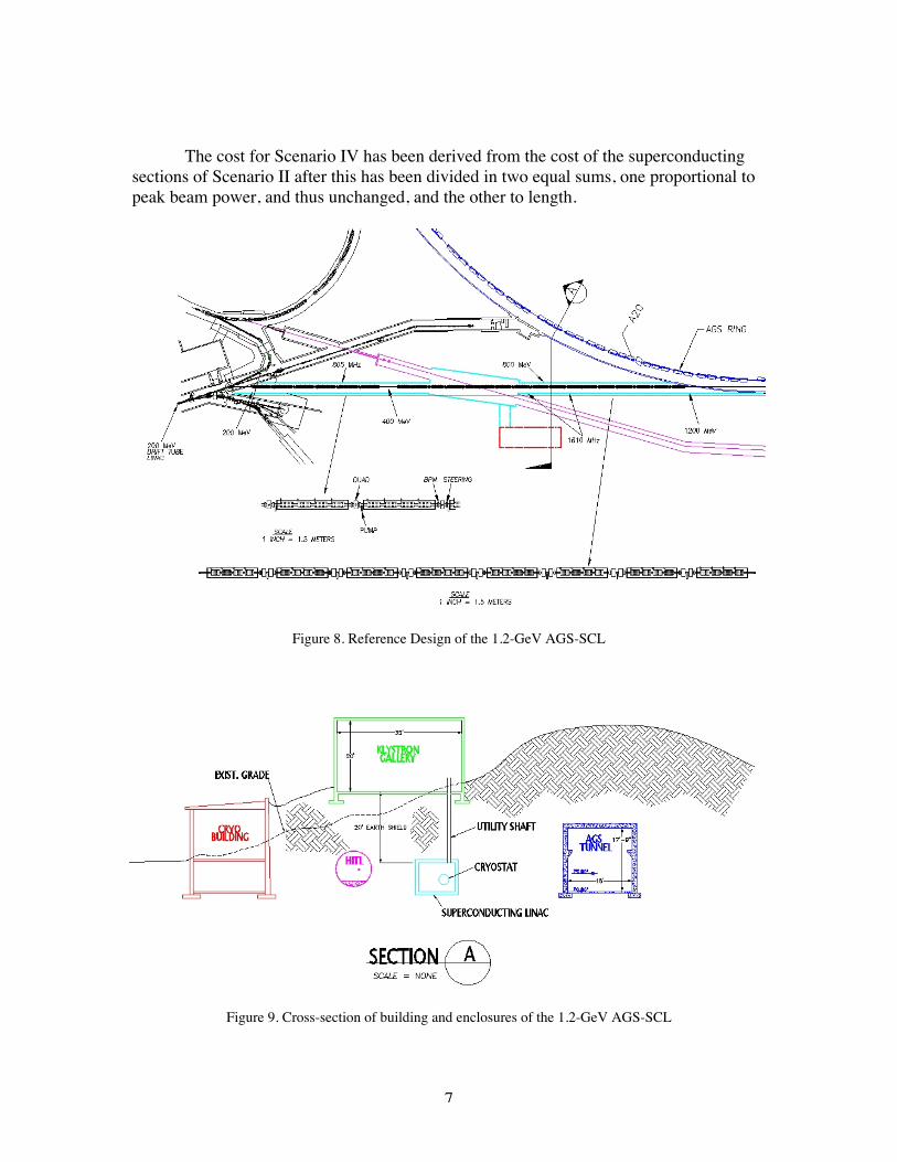
Scenario IV. This has been our reference design all along [3]. For that we required astraight-line transport, as compact as possible, for acceleration over a path of about 120 mto at least 1.2 GeV. The solution of this Scenario is shown in Figure 8, with the cross-section of the Linac tunnel, cryogenic building and the klystron gallery givenschematically in Figure 9 (prepared by T. Nehring). But in order to allow this Scenario onour agenda, differently from the other Scenarios, we had to re-design the Super-Conducting Linac sections. Indeed we have seen that using the geometry of the cryo-modules of both sections of the SNS-SCL, without modifications, one needs a total spaceof 190 m for acceleration to 1.2 GeV against the available 120 m. To get a more compactlayout we had to design the AGS-SCL with three sections, instead of two as in the SNS-SCL: (i) a Low-β section from 200 to 400 MeV at 805 MHz, (ii) a Medium-β sectionfrom 400 to 800 MeV, and (iii) a High-β section from 800 MeV to 1.2 GeV, the last twosections both operating at 1.61 GHz. The Low-β section was considerably shortened with4 instead of three cavities per cryo-module. Because of the higher accelerating gradientpacking, the beam dynamics was found to be at the limit of longitudinal stability. Theother sections operated at the higher RF frequency for a more compact acceleratinggradient. Moreover, space like warm-to-cold transitions and warm insertions wereconsiderably shortened to the limit of engineering. Because of the large deviations fromthe design of the SNS-SCL now the uncertainties on both the performance and the cost ofthe AGS-SCL increase.
A comparison of the four Scenarios described above is given in Table 3.Obviously Scenario I is the most straight forward and likely the most secure, but also themost expensive. Scenario II requires study of the dispersion, whereas Scenario III is themost economic and probably the most preferable, but requires a commitment to themodification of the 200-MeV DTL. Finally Scenario IV is the one that most deviatesfrom the design of the SNS-SCL and therefore uncertain. Also this last Scenario does notallow acceleration to 1.5 GeV.
7
The cost for Scenario IV has been derived from the cost of the superconductingsections of Scenario II after this has been divided in two equal sums, one proportional topeak beam power, and thus unchanged, and the other to length.
Figure 8. Reference Design of the 1.2-GeV AGS-SCL
Figure 9. Cross-section of building and enclosures of the 1.2-GeV AGS-SCL

8
Table 3. Comparison of AGS-SCL ScenariosScenario I Scenario II Scenario III Scenario IV
Feature Full Straight SNSLinac
Full Bent SNSLinac
DTL Upgrade to400 MeV
Major departurefrom SNS design
Energy Range 0 - 1.5 GeV 0.2 – 1.5 GeV 400 MeV 1.2 GeV 200 MeV 1.2 GeVLength, m 290 / 340 190 / 240 120 / (170) 120Cost, M$ 300 / 350 220 / 270 190 / (240) 180 (??)Comments Too Expensive but
is SNS-SCLHorizontal Bending Difficult Upgrade
to 1.5 GeVUncertain Cost andPerform. Estimate
Revision of the Reference 1.2-GeV AGS-SCL Design
The original design of the 1.2-GeV AGS-SCL assumed a RF of 1.61 GHz for theMedium and High-β sections. That frequency has not been demonstrated yet in any otheraccelerator facility, though we have received reassurance from electronic industries thatpower amplifier sources could be easily made available. Moreover, the design of RFcouplers, waveguides, circulators and electronic components for that frequency requiresconsiderable and costly program of research and development. We have thus consideredat this stage the possibility to make use of the same 805 MHz RF frequency for the entireAGS-SCL as done in the SNS-SCL, except that we shall still continue to employ three β-sections, because of the larger required increment in energy (1.2 versus 1.0 GeV) and tooptimize further the transit time factors with three different types of cavity cells. Forcomparison, the layout of the two SCL is shown in Figure 10. Cost and length arecompared in Table 4.
Figure 10. The AGS and SNS Super-Conducting Linacs
Medium Front End Low-Energy Energy High-Energy
RT Linac Section Section Section To the AGS
201.25 MHz 805 MHz 805 MHz 805 MHz
200 MeV 400 MeV 800 MeV 1.2 GeV
Front End Medium-Beta High-Beta DTL CCL Section Section To the SNS
402.5 MHz 805 MHz 805 MHz 805 MHz
185.6 MeV 387 MeV 1.0 GeV

9
Table 4. Cost and Length Comparison of AGS and SNS SCLSNS AGS
Energy 185.6 MeV - 1.0 GeV 200 MeV - 1.2 GeVLength, m 160 120Cost, M$ 190 180Average Gradient, MeV/m 5.09 8.33Cost/Length, M$/m 1.2 1.5Cost/Energy, M$/MeV 0.23 0.18
Each of the SCL section is made of a sequence of cryo-modules (or cryostats) asshown in Figure 11. Each cryo-module contains a number of cavities all with the samenumber of RF cells. The cavities are designed to operate in π mode; thus the gap g of acell, to optimize the energy transfer to the particle, is adjusted to match half ofwavelength according to g = βc λ / 2, where βc is a reference value equal to all the cells inthe same section, somewhere in between the entrance and exit values of the particlevelocity β. We follow very closely the design of the SNS-SCL, and we adopt one RFcoupler per cavity and one klystron per coupler. Cavities are separated by a distance longenough to avoid coupling, and at the both ends of a cryostat there is a cold-to-warmtransition. Finally, cryo-modules are separated by warm insertions long enough toaccommodate focusing quadrupole magnets, vacuum pumps, steering magnets, beamposition monitors and other components. The active length, where there is acceleratingfield, is essentially the sum of all the RF cells involved. The inactive length is the totallength of all the drifts listed above where there is no acceleration. For an optimized andefficient acceleration it is important that the ratio of active to inactive length is a large aspossible. Another important parameter is the transit time factor T of a particle of a givenvelocity crossing a cell or a cavity since the field varies in time as the particle travels. Theactual accelerating gradient in the active length is then given by G = T Eacc cos φs, whereφs is the phase lag between a beam bunch and the RF waveform, and Eacc is the averageaxial RF electric field. These quantities have about the same values in the two SCL.
To accommodate the AGS-SCL within the allowable space, we have also reducedthe overall inactive length as shown in Table 5. The active length remains essentially thesame in both SCL, since the geometry of the RF cells is also the same. The majorgeometrical changes are as follows: (i) The internal diameter of the cavities has beenraised from 8 to 10 cm, to provide more transverse aperture since we are adopting asingle quadrupole per period for focusing; and also because the beam emittance from theBNL DTL is a factor 3 larger than the value in the SNS-SCL; (ii) The cavity separationlowered from 38.5 cm down to 32 cm, that may require a more detail inspection of cavitycoupling and stray field by running codes like SUPERFISH; (iii) The warm-to-coldtransitions lowered from 71-76 cm down to 44 cm, that requires a careful engineeringanalysis to verify whether it is possible to accommodate all the required cryogenic pipingin such reduced space; (iv) The warm insertion lowered from 1.6 m down to 1.0 m, thatwill force us to a FODO arrangement of the focusing quadrupoles. All other dimensionsremained unchanged as in the SNS-SCL design. All the proposed modifications for theAGS-SCL require a careful engineering analysis to ensure their feasibility, and that donot cause too severe constrain to the design, fabrication, and operation of thecomponents.

10
Figure 11. Sequence of Cryostats, Cavities and RF Cells in one SCL Section
Table 5. Inactive versus Active Length Distribution in the SNS and AGS SCL (805 MHz)
Lcryo Period Cryo-Module
Lins C D Insertion
Lw
C dc Cavity D
Lw A B Lw
CavityInterval
Couplers
SNS - med SNS - high AGS - LE AGS - ME AGS - HEβc 0.61 0.81 0.615 0.740 0.851Cell, cm 11.36 15.08 11.45 13.78 15.84# Periods 11 12 6 7 6# Cavities 3 4 4 4 4# Cells 6 6 8 6 6Cavity Diam. 8 cm 8 cm 10 cm 10 cm 10 cmCavity Separ. 38.5 cm 38.5 cm 32 cm 32 cm 32 cmW-C Tran. 71 cm 76 cm 44 cm 44 cm 44 cmWarm Insertion 1.60 m 1.60 m 1.00 m 1.00 m 1.00 mPeriod Length 5.835 m 7.894 m 6.504 m 6.150 m 6.642 mSection Length 64.19 m 94.73 m 39.03 m 43.03 m 39.85 mLinac Length 158.9 m 121.9 m

11
RF Comparison and Considerations of the 200-400 MeV Sections
The Low-β section of the AGS-SCL has about the same energy range of theMedium-β section of the SNS-SCL, and thus the two sections would be expected to be ofabout the same design, also because they both use the same RF frequency of 805 MHz,and have the same βc reference value. Nevertheless, for obvious reasons that will beexplained below, the Medium-β section of the SNS-SCL is too long with a loweraccelerating average gradient. That length would not possibly fit on the chosen BNL site,and we had to consider a more compact arrangement. Inspection of Table 5 shows amajor deviation in our design: there are four cavities in each cryo-module, instead ofthree, and there are 8 RF cells instead of 6. The total number of RF cells is about thesame, 198 in the SNS and 192 in the AGS SCL, indicating that the energy average gainper cell is about the same, as it should be, but there are fewer number of cryo-modules inour design: 6 against 11. This yields to a considerable shorter length of the section (39versus 64 m), though each period is somewhat longer (6.5 versus 5.8 m), and to an energygain per period almost as twice as large, as shown in Table 6. The reason is that the activeto the period length ratio is also considerably higher. There is nonetheless a concernabout too large an energy gain per period; the study of the beam dynamics [4] shows thatone is really operating very close to the stability limit of the longitudinal motion. Toavoid this, the SNS-SCL was expressly designed with a lower average gradient, and thuswith a more diluted Medium-β section leading to a softer evolution of energy oscillations.Operating so close to the longitudinal stability limit is a concern for a potential of beamloss [5] and consequent activation of the RF and mechanical components. Otherwise, thelocal accelerating gradients as well as the required peak RF power in the couplers isabout the same.
RF Comparison and Considerations of the High-Energy Sections
The high energy sections of both the SCL adopt about the same design. Bothoperate at 805 MHz, and have similar RF cells geometry. Both include 4 cavities, all with6 RF cells, in each of the cyo-modules. There are 13 cryo-modules in the AGS-SCLversus the 12 in the SNS-SCL. Since the acceleration energy range is 200 MeV larger inthe AGS-SCL, that means that the local accelerating gradient, that is in the active length,is higher, as one can see by inspecting Table 6. The numbers have been derived assuminga constant energy gain per cryo-module, that is constant accelerating gradient G. Thoughless than in the low-energy section, also here the ratio of active length to the period
Table 6. RF Comparison between the different Sections of the SNS and AGS SCLSNS - med SNS - high AGS - LE AGS - ME AGS - HE
ΔE / Period, MeV 18.31 51.08 33.33 57.14 66.67Active/Period Length 0.350 0.459 0.563 0.538 0.572Gradient, MeV /m 8.96 14.10 9.10 17.28 17.55Axial Field Eacc, MV/m -- -- 14 21 19RF Phase, φs -- -- 30o 25 o 20 o
Coupler Power, kW 408 522 350 600 700

12
length is higher by 20-30%. Consequently the average axial field Eacc is also higher, butstill expected to be within the surface limit. The RF power in the couplers is alsocorrespondingly higher.
Engineering Verification
It is important at this point to verify thatthe space specifications given above for themodified AGS-SCL are consistent with themanufacturing of the cryostats, theaccommodation of the beam components in thewarm insertions, and that there are no majorobstacles or limitations to the implementation ofthe entire SCL on the selected BNL site. Forinstance Figure 12 shows, more or less in scale,the inter-cavity space and the RF power couplerwith flanges, the dimension of which have beentaken from the SNS design. The space seems tobe indeed adequate; but there is the concern thata similar coupler to remove losses to the HigherOrder Modes (HOM) may also be required, andin that case there may not be sufficient space between cavities. The concern is not reallydirected to the power loss to be absorbed by the cryogenic system, since this in the AGS-SCL is a factor 45 lower than in the SNS-SCL, but in the single bunch and bunch-to-bunch instabilities that may result from the spurious resonating modes of the cavities.
Figure 13 is an outline of a Warm Insertion with several beam components. Thereis room for only one quadrupole about 35 cm in length; otherwise there is a reasonable
amount of space. It is also possible toplace the steering magnet and the BeamPosition Monitor (BPM) within theaperture of the quadrupole magnet ifeven more space is required.
The design of the Low-β sectionis the one that most deviates from theSNS-SCL design. Figure 14 givesevidence that four cavities, each with 8cells, can reasonably well be inserted ina cryostat of the assigned dimension forthat section. Similarly, Figure 15 showsmore details about the bridging of twocryo-modules together. We opt for a
vertical layout where the RF couplers are installed directly above the cavities, and joinedto the waveguides by means of a RF window in a direct straight line, avoiding bending.The power sources, in our case klystrons, are then located in a gallery above the
Figure 12. Power Coupler in the Inter-Cavity Space
32 cm
QuadValve Valve
BPM Pump Flange
Steering Bellow
100 cm
Figure 13. Warm Insertion with Beam Components

13
Figu
re 1
4. A
ssem
bly
of a
Low
-β S
ectio
n Cr
yo-M
odul
e
Cryo
stat En
d-Ca
p
Wav
egui
de
Cavi
ty
RF W
indo
w
RF C
oupl
er
Vac
uum
Pum
p
Supp
ort S
tand
Floo
r

14
Linac tunnel. The same Figure 15 shows the piping for the Helium flow just above thecryostats. This arrangement is different from the one adopted by the SNS design wherethe couplers and the Helium piping are located below, an arrangement that in our viewcauses some logistic problem and difficulty of access. The SNS arrangement wassuggested by the choice to isolate the vacuum and the helium flow in case of a singlecryostat failure, so it could be possible to disconnect it for replacement without warmingup the rest of the section. But here in case of failure we propose disconnecting the entiresection where the failure occurs from the other two, bringing the entire section to warmtemperature, and operating the replacement. This simplifies considerably the refrigerationpiping with disconnect elements located only at each end of the section that includes 6modules in the Low and High-β sections (each 40 m long) and 7 in the Medium-β section(44 m long). But the same procedure will require a longer period of time to operate areplacement, at best may be one week. Adopting this procedure, there is then hope that ashorter cold-to-warm transition of 44 cm at each end of the cryostat can indeed besufficient.
Conclusion
We have demonstrated that a 1.2-GeV SCL for the AGS Upgrade is feasible andthat can be designed to fit the space available between the end of the BNL 200-MeV DTLand the entrance to the AGS tunnel. The design is similar to that of the equivalent SNS-SCL, the only one we have today to make reference to for performance and costcomparison. Yet we had to adopt some major modifications (namely deviations) toshorten the entire SCL from 190 down to 120m. This was accomplished in twosubstantial ways: (i) By reducing the length of the drifts, namely the inter-cavity spacing,the cold-to-warm transitions, and the warm insertions; (ii) By making a more compactdesign of the Low-β section with four cavities per cryo-module and 8 RF cells per cavity.The first way raises of course some engineering concerns that though do not seem to us atthe moment very compelling; the second way pushes the longitudinal motion to a limit ofstability, and we worry here about the effect of possible errors.
By extrapolating from the SNS-SCL, it seems that the total cost of the AGS-SCLproject is about 180 M$ (all included). On the other end, a bottom up cost estimate gaveas a result a lower figure of about 100 M$, but without including burden charges thatremained to be specified.
Concerning the possibility to raise the energy from 1.2 to 1.5 GeV, it is obviousthat with the adopted Scenario (IV) it will not be possible to add more cryo-modules aspart of a subsequent section (1,200 to 1,500 MeV). Nevertheless Superconducting RFCavity is still a fresh new technology with surprises and advancement almost every day.Thus it cannot be excluded that in the near future higher gradients can be achieved andwith that also higher power RF couplers. If this is the case, then it may be sufficient toraise the power (and, with that, the gradient) by 30 % in the entrance of all the couplers ofthe Medium and High-β Sections. By doing this, it should be noticed, the longitudinalphase oscillation reaches about 180o on the first period of each of the two Sections, aspresently is the case for the Low- β Section.

15
Figu
re 1
5. A
ssem
bly
of tw
o Lo
w-β
Sec
tion
Cryo
-mod
ules
with
War
m In
serti
ons
Kly
stron
Gal
lery
Kly
stron
sPo
wer
Sup
ply
Rack
s
War
mIn
serti
on
16
References
[1] AGS Super Neutrino Beam Facility. Coordinators: M. Diwan, W. Marciano, W. Weng. Editor: D. Raparia. BNL-71228 Informal Report. 15 April 2003.[2] http://www.sns.gov/documentation/pubs.htm[3] A.G. Ruggiero et al., Design of 1.2-GeV SCL as New Injector for the BNL AGS. Proceedings of SRF 04 Workshop, Travemunde (Lubeck), Germany, September 2003.[4] A.G. Ruggiero, Design Considerations on a Proton Superconducting Linac. BNL-Internal Report 62312. August 1995.[5] A.G. Ruggiero, Longitudinal Mismatch in SCL as a Source of Beam Halo. Proceedings of HALO’03 Workshop, Montauk, New York, May 2003. AIP Conference Proceedings 693, page 69.
Acknowledgments
I have discussed this project with several experts in the field from manyinstitutions in Europe and in the States. I have received from all advice, suggestions anduseful comments for which I am grateful. I have learned a lot from their expertise. Inparticular, I am grateful to D. Raparia, T. Nehring, J. Tuozzolo, K. C. Wu, and others atBNL for their assistance and contribution to this project.
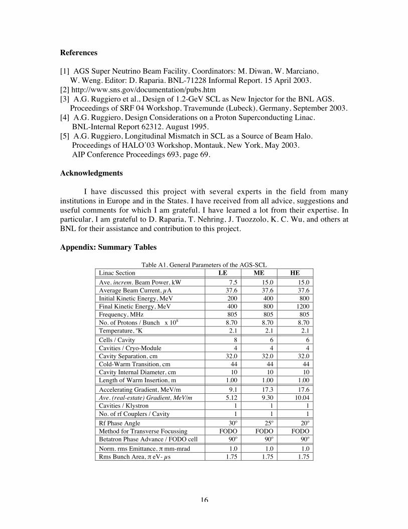
Appendix: Summary Tables
Table A1. General Parameters of the AGS-SCLLinac Section LE ME HEAve. increm. Beam Power, kW 7.5 15.0 15.0Average Beam Current, µA 37.6 37.6 37.6Initial Kinetic Energy, MeV 200 400 800Final Kinetic Energy, MeV 400 800 1200Frequency, MHz 805 805 805No. of Protons / Bunch x 108 8.70 8.70 8.70Temperature, oK 2.1 2.1 2.1Cells / Cavity 8 6 6Cavities / Cryo-Module 4 4 4Cavity Separation, cm 32.0 32.0 32.0Cold-Warm Transition, cm 44 44 44Cavity Internal Diameter, cm 10 10 10Length of Warm Insertion, m 1.00 1.00 1.00Accelerating Gradient, MeV/m 9.1 17.3 17.6Ave. (real-estate) Gradient, MeV/m 5.12 9.30 10.04Cavities / Klystron 1 1 1No. of rf Couplers / Cavity 1 1 1Rf Phase Angle 30o 25o 20o
Method for Transverse Focussing FODO FODO FODOBetatron Phase Advance / FODO cell 90o 90o 90o
Norm. rms Emittance, π mm-mrad 1.0 1.0 1.0Rms Bunch Area, π eV- µs 1.75 1.75 1.75

17
Table A2. Summary of the AGS-SCL DesignLinac Section LE ME HEVelocity, β: In Out
0.56590.7128
0.71280.8416
0.84160.8985
Cell Reference β0 0.615 0.740 0.851Cell Length, cm 11.45 13.78 15.85Total No. of Periods 6 7 6Length of a period, m 6.505 6.147 6.643FODO-Cell ampl. func., βQ, m 22.09 20.87 22.56
Total Length, m 39.03 43.03 39.8667.5Coupler rf Power, kW (*) 350 600 700
Energy Gain/Period, MeV 33.33 57.14 66.67Total No. of Klystrons 24 28 24Klystron Power, kW (*) 350 600 700Rs/Q0, ohm 120.5 145.0 166.7Q0 x 1010 1.27 1.41 1.50Ave. Axial Field, Eacc, MV/m 14.2 20.6 18.9Filling Time, ms 0.21 0.23 0.19Ave. Dissipated Power, W 0.52 1.38 1.11Ave. HOM-Power, W 0.21 0.35 0.47Ave. Cryogenic Power, W 66.8 73.8 69.3Ave. Beam Power, kW 7.5 15 15Total Ave. rf Power, kW (*) 13.7 29.1 283Ave. AC Power for rf, kW (*) 30.3 64.7 63.0Ave. AC Power for Cryo., kW 47.4 52.3 49.2Total Ave. AC Power, kW (*) 78 117 112Efficiency, % (*) 22.1 22.1 22.1
(*) Including 50% rf power contingency Cryo-Efficiency 0.141 % Beam Duty Cycle 0.179 %


![December 2016 Fleet Upgrade & Replacement … 2016 Fleet Upgrade & Replacement Catalog IHS4: DDG-1000 Destroyer equip w/ electric propulsion, 155 mm Advanced Gun [AGS] fires GPS-guide](https://img.dokumen.tips/doc/110x75/5bdaaf9d09d3f2e1768d2de1/december-2016-fleet-upgrade-replacement-2016-fleet-upgrade-replacement-catalog.jpg)