Embed Size (px)
Citation preview

ww.sciencedirect.com
i n t e r n a t i o n a l j o u r n a l o f h y d r o g e n en e r g y 3 8 ( 2 0 1 3 ) 1 4 5 9 5e1 4 6 1 7
Available online at w
journal homepage: www.elsevier .com/locate/he
Review
Review of hydrogen storage techniquesfor on board vehicle applications
D.J. Durbin, C. Malardier-Jugroot*
Department of Chemistry and Chemical Engineering, Royal Military College of Canada, Kingston K7L7B4, Canada
a r t i c l e i n f o
Article history:
Received 11 March 2013
Accepted 17 July 2013
Available online 4 October 2013
Keywords:
Hydrogen storage
Chemical hydrides
Adsorption materials
Metal-organic frameworks
Carbon
Nanostructures
* Corresponding author. Tel.: þ1 6135416000.E-mail address: Cecile.Malardier-Jugroot@
0360-3199/$ e see front matter Crown Copyri
http://dx.doi.org/10.1016/j.ijhydene.2013.07.05
a b s t r a c t
Hydrogen gas is increasingly studied as a potential replacement for fossil fuels because
fossil fuel supplies are depleting rapidly and the devastating environmental impacts of
their use can no longer be ignored. H2 is a promising replacement energy storage molecule
because it has the highest energy density of all common fuels by weight. One area in which
replacing fossil fuels will have a large impact is in automobiles, which currently operate
almost exclusively on gasoline. Due to the size and weight constraints in vehicles, on board
hydrogen must be stored in a small, lightweight system. This is particularly challenging for
hydrogen because it has the lowest energy density of common fuels by volume. Therefore,
a lot of research is invested in finding a compact, safe, reliable, inexpensive and energy
efficient method of H2 storage. Mechanical compression as well as storage in chemical
hydrides and absorption to carbon substrates has been investigated. An overview of all
systems including the current research and potential benefits and issue are provided in the
present paper.
Crown Copyright ª 2013, Hydrogen Energy Publications, LLC. Published by Elsevier Ltd. All
rights reserved.
1. Introduction battery that carries an electric charge in addition to an ICE.
Human society currently relies primarily on fossil fuels for
energy production. This energy storagemedium is so effective
that it spurred the Industrial Revolution. However, in the 21st
century, it is clear that fossil fuels cannot continue to be the
primary energy source because resources are rapidly
depleting and significant emissions of greenhouse gases result
from fossil fuel burning. As a result, a cleaner, more sustain-
able energy source is being actively pursued [1,2].
One of the largest users of fossil fuels ismotorized vehicles,
which burn gasoline in an internal combustion engine (ICE).
The first attempt to limit the use of fossil fuels in automobiles
was the development of hybrid vehicles, which contain a
rmc.ca (C. Malardier-Jugght ª 2013, Hydrogen Ene
8
Hybrid vehicles have had some success but they are not a
solution because they still require some input of fossil fuels.
As a result, the next generation of automobiles will likely be
fuel cells vehicles (FCV). FCVs take in hydrogen gas to power a
hydrogen fuel cell, such as a polymer electrolyte membrane
fuel cell. These vehicles are desirable because they produce no
environmentally damaging emissions. In addition, once a
sustainable method for H2 gas production is developed, FCVs
will have a constant fuel supply [3].
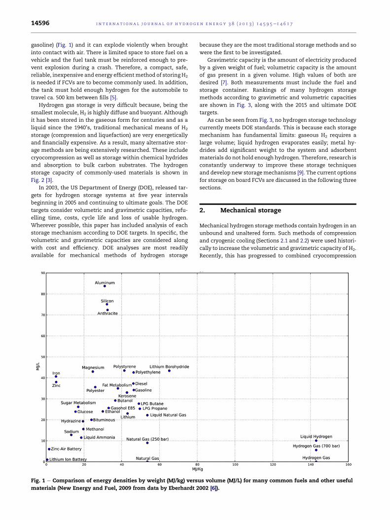
At 143.0 MJ/kg, hydrogen has the highest energy density of
common fuels by weight (three times larger than gasoline) [4].
Unfortunately, at 0.0108 MJ/L, gaseous H2 also has the lowest
energy density by volume (over 3000 times smaller than
root).rgy Publications, LLC. Published by Elsevier Ltd. All rights reserved.
i n t e rn a t i o n a l j o u r n a l o f h y d r o g e n en e r g y 3 8 ( 2 0 1 3 ) 1 4 5 9 5e1 4 6 1 714596
gasoline) (Fig. 1) and it can explode violently when brought
into contact with air. There is limited space to store fuel on a
vehicle and the fuel tank must be reinforced enough to pre-
vent explosion during a crash. Therefore, a compact, safe,
reliable, inexpensive and energy efficientmethod of storing H2
is needed if FCVs are to become commonly used. In addition,
the tank must hold enough hydrogen for the automobile to
travel ca. 500 km between fills [5].
Hydrogen gas storage is very difficult because, being the
smallest molecule, H2 is highly diffuse and buoyant. Although
it has been stored in the gaseous form for centuries and as a
liquid since the 1940’s, traditional mechanical means of H2
storage (compression and liquefaction) are very energetically
and financially expensive. As a result, many alternative stor-
age methods are being extensively researched. These include
cryocompression as well as storage within chemical hydrides
and absorption to bulk carbon substrates. The hydrogen
storage capacity of commonly-used materials is shown in
Fig. 2 [3].
In 2003, the US Department of Energy (DOE), released tar-
gets for hydrogen storage systems at five year intervals
beginning in 2005 and continuing to ultimate goals. The DOE
targets consider volumetric and gravimetric capacities, refu-
elling time, costs, cycle life and loss of usable hydrogen.
Wherever possible, this paper has included analysis of each
storage mechanism according to DOE targets. In specific, the
volumetric and gravimetric capacities are considered along
with cost and efficiency. DOE analyses are most readily
available for mechanical methods of hydrogen storage
Fig. 1 e Comparison of energy densities by weight (MJ/kg) vers
materials (New Energy and Fuel, 2009 from data by Eberhardt 2
because they are the most traditional storage methods and so
were the first to be investigated.
Gravimetric capacity is the amount of electricity produced
by a given weight of fuel; volumetric capacity is the amount
of gas present in a given volume. High values of both are
desired [7]. Both measurements must include the fuel and
storage container. Rankings of many hydrogen storage
methods according to gravimetric and volumetric capacities
are shown in Fig. 3, along with the 2015 and ultimate DOE
targets.
As can be seen from Fig. 3, no hydrogen storage technology
currently meets DOE standards. This is because each storage
mechanism has fundamental limits: gaseous H2 requires a
large volume; liquid hydrogen evaporates easily; metal hy-
drides add significant weight to the system and adsorbent
materials do not hold enough hydrogen. Therefore, research is
constantly underway to improve these storage techniques
and develop new storagemechanisms [9]. The current options
for storage on board FCVs are discussed in the following three
sections.
2. Mechanical storage
Mechanical hydrogen storagemethods contain hydrogen in an
unbound and unaltered form. Such methods of compression
and cryogenic cooling (Sections 2.1 and 2.2) were used histori-
cally to increase the volumetric and gravimetric capacity of H2.
Recently, this has progressed to combined cryocompression
us volume (MJ/L) for many common fuels and other useful
002 [6]).
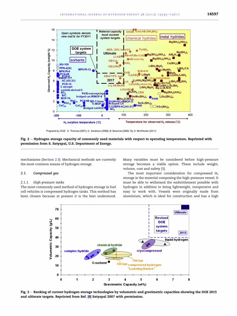
Fig. 2 e Hydrogen storage capacity of commonly used materials with respect to operating temperature. Reprinted with
permission from S. Satyapal, U.S. Department of Energy.
i n t e r n a t i o n a l j o u r n a l o f h y d r o g e n en e r g y 3 8 ( 2 0 1 3 ) 1 4 5 9 5e1 4 6 1 7 14597
mechanisms (Section 2.3). Mechanical methods are currently
the most common means of hydrogen storage.
2.1. Compressed gas
2.1.1. High-pressure tanksThe most commonly used method of hydrogen storage in fuel
cell vehicles is compressed hydrogen tanks. This method has
been chosen because at present it is the best understood.
Fig. 3 e Ranking of current hydrogen storage technologies by vo
and ultimate targets. Reprinted from Ref. [8] Satyapal 2007 with
Many variables must be considered before high-pressure
storage becomes a viable option. These include weight,
volume, cost and safety [3].
The most important consideration for compressed H2
storage is the material composing the high-pressure vessel. It
must be able to withstand the embrittlement possible with
hydrogen in addition to being lightweight, inexpensive and
easy to work with. Vessels were originally made from
aluminium, which is ideal for construction and has a high
lumetric and gravimetric capacities showing the DOE 2015
permission.

i n t e rn a t i o n a l j o u r n a l o f h y d r o g e n en e r g y 3 8 ( 2 0 1 3 ) 1 4 5 9 5e1 4 6 1 714598
thermal conductivity. However, aluminium vessels were not
strong enough and often could not comply with safety stan-
dards. Therefore, the vessel material has changed to a carbon
fibre/epoxy composite (carbon fibre reinforced plastic, CFRP)
in recent years [3,10].
CFRP vessels are lightweight and very strong, but they have
relatively low thermal conductivity. Therefore, the material
must be kept below 358 K at all times to comply with safety
requirements. This temperature constraint can be an issue,
especially during filling the tank when the exothermic
compression of the gas causes the temperature to rise dras-
tically. The CFRP unit is also sensitive to fire and high tem-
peratures, which cause a degradation of its mechanical
properties. There is a large concern that an explosion would
result if the H2 storage vessel was subjected to a fire, such as
might occur in a car crash [5,11].
At present, two types of tanks are commonly used: type IV
is composed entirely of CFRP; type III contains metal-lined
CPRP and so encompasses properties of both the early
aluminium tanks and the currently used CFRP tanks. Type III
is preferred, but its cost is prohibiting. As a result, alternative
tanks under investigation. One such system is discussed
below [3].
An alternative to the currently used type III and IV vessels
is a CFRP tank reinforced with a space-filling skeleton. This
tank will use struts and web elements in tension to resist the
force of compressed gas. Addition of the skeleton should allow
for lighter, stronger tanks designed in any shape (current
tanks must be round in order to achieve a high membrane
resistance and low surface-to-volume ratio). However, they
will not become a viable technology until the manufacturing
process and long-term system durability are improved [3,12].
Returning to current H2 storage tanks, in 2009 the DOE
Hydrogen Program analyzed the potential for on board H2
storage in type IV tanks containing 5.6 kg of recoverable H2.
The current values and target of the four main criteria are
discussed below.
Gravimetric capacity: A 345 atm tank was found to have a
gravimetric capacity of 5.5 wt% (6.9 wt% in physically perfect
conditions). A 690 atm tank was less weight efficient with a
gravimetric capacity of 5.2 wt% (theoretical potential of 6.5 wt
%). It is unlikely to meet the ultimate DOE target of 7.5 wt% for
either tank [7].
Volumetric capacity: A 345 atm tank was found to have a
volumetric capacity of 17.6 g H2/L (18.6 g/L if the empty tank
pressure is reduced to 3 atm). This will not even reach the 2010
DOE target of 28 g/L. A 690 atm tankwasmore volume efficient
with a volumetric capacity of 26.3 g/L (possible increase to
27.2 g/L). This systemwill not reach the ultimate DOE target of
70 g/L [7].
Cost: The manufacturing costs were $15.4/kWh for the
345 atm tank and $18.7/kWh for the 690 atm tank. These are
over four times the target of $4/kWh. The cost of compressed
H2 fuelwas $4.22/gge for the 345 atm tank and $4.33/gge for the
690 atm tank where gge is a gasoline gallon equivalent. This is
approximately two times larger than the $2.30/gge target [7].
Efficiency: The 345 atm compressed gas tank had an effi-
ciency of 56.5%; the 690 atm tank had the slightly lower effi-
ciency of 54.2%. Both values are within reach of the 60% DOE
target [7].
Of the four obstacles discussed, cost is considered the
greatest barrier. It is largely contributed to the carbon fibre
composing the tank with a large contribution from assembly
and some for binding. Even if the cost is lowered, there is
concern that high-pressure tanks will not be accepted by the
general public because they are perceived as unsafe [3].
2.1.2. Capillary storageAn alternative option for compressed hydrogen storage is
capillaries or microspheres. These vessels are advantageous
because (i) they require less hydrogen infrastructure because
the capillaries will be filled at the fuel plant before delivery to
the filling station; (ii) capillaries are safer because each one
acts as an individual high-pressure vessel containing only a
small amount of H2; (iii) the system is lightweight because
minimal material is required for each capillary and many can
be stored together in a larger thin tank [15, 3].
At present, capillary H2 storage greatly exceeds DOE targets
in many areas. In addition to high gravimetric capacity, cap-
illaries should be able to store enough H2 to travel over 500 km
in a 60 L tank that weighs only 50 kg by 2015. However, capil-
lary storage does not meet the DOE targets for volumetric ca-
pacity and a large amount of energy is needed to release H2
from the capillaries. The systems also have limited long term
durability. Therefore, they are not currently in use [3,15].
2.2. Cryogenic storage: liquid hydrogen
Liquefying hydrogen is a means of increasing volumetric en-
ergy density. It is also called cryogenic storage because
liquefaction is performed by cooling H2 to 20 K. Although it is
an energy expensive process, it increases H2 volumetric en-
ergy density from 2.5 or 5 MJ/L (for compressed H2 at 345 and
690 atm respectively) to 8 MJ/L (for liquid hydrogen LH2). As a
result, less volume is required for storage so a smaller, lighter
container can be used. This allows longer distances to be
driven (Fig. 4). Because of this great potential, LH2 storage was
extensively studied in the 1980’s and 1990’s [13].
Ifhydrogenisstored intheliquidformonboardaFCV, itmust
be maintained below its boiling point of 20 K. Therefore, heat
intrusion must be kept at the lowest possible level. To accom-
plish this, the original LH2 tanks were metallic double-walled
vessels. The inner vessel had multilayer insulation composed
of several metallic foil layers separated by glass wool; space
between the inner and outer vessels was evacuated to create a
vacuum. This storage system is often referred to as vacuum
superinsulation (Fig. 5). In recent years, pressure release valves
havebeenadded for safety reasons. Inaddition,newtanksmust
beable to releasegaseousH2 aswell as LH2. ALH2 tankwasmost
recently tested inaGMHydroGen3; itwas found tohold 4.6 kg of
LH2 with a total systemweight of 90 kg [13,14].
Despite important improvements to volumetric density,
LH2 storage is not frequently used for several reasons. First, at
least 35% of the fuel’s energy content is used to liquefy it. This
is three times more energy than is needed to compress H2 to
690 atm. Second, LH2 evaporates very easily during delivery
and refuelling. Third, LH2 pressurizes quickly while on-board
vehicles as it absorbs heat from the environment. Therefore,
the tank must be vented every 3e5 days during inactivity to
prevent dangerous and costly boil-off losses; if boil-off is not

Fig. 4 e Comparison of compressed gaseous H2 (GH2; grey)
and liquid H2 (LH2; black) based on driving range, storage
volume, storage weight, effective energy content and
primary energy content where the primary energy content
is the energy required to compress or liquefy H2. Reprinted
from Ref. [13] with permission.
Fig. 6 e Volumetric energy density (MJ/L) versus
gravimetric energy density (MG/kg) for several common
fuels. Reprinted from Ref. [16] with permission.
i n t e r n a t i o n a l j o u r n a l o f h y d r o g e n en e r g y 3 8 ( 2 0 1 3 ) 1 4 5 9 5e1 4 6 1 7 14599
controlled, the entire hydrogen store will evaporate in ca. 2
weeks. Even if these problems could be overcome, the volu-
metric energy density of LH2 (ca. 8 MJ/L) is substantially less
than that of gasoline (32 MJ/L) and diesel fuel (36 MJ/L) (Fig. 6).
As a result, studies of mechanical hydrogen storage have
largely shifted to cryocompressed H2 (Section 2.3) in recent
years [9,14e16].
2.3. Cryocompressed hydrogen
The newest hydrogen storage technologies combine compres-
sion and cryogenic storage of H2 to produce cryocompressed
hydrogen. This includes pressurized liquid hydrogen, cooled
compressed hydrogen gas and two phase systems of liquid
hydrogen with vapour in the headspace [17].
2.3.1. Compressed liquid hydrogenThe storage density of LH2 is higher in insulated pressure
vessels because it is slightly compressible: at 21 K, its density
increases from 70 g/L at 1 atm to 87 g/L at 237 atm [17].
Fig. 5 e Liquid hydrogen storage tank showing the LH2 storage
Ref. [14] with permission.
Cryocompressed vessels are preferred over traditional LH2
storage containers because they are better able to withstand
heat since H2 within the vessel can be vented at a higher
temperature. Venting stops when the tank reaches ambient
temperature. When this occurs, the pressure within the tank
is maintained so that the H2 density remains at 30% of the
initial LH2 density. This is better for storage and makes the
tanks much safer during dormant periods. In addition, cry-
ocompressed H2 vessels have the potential to increase the
volumetric energy density by eliminating unused space in the
container. This can be done because H2 becomes a supercrit-
ical fluid at pressures greater than 13 atm before the tank
must be vented [17].
A sophisticated cryogenic capable pressure vessel (Fig. 7)
was recently developed at the Lawrence Livermore National
Laboratory (LLNL) in California, USA. It has a high storage
capacity (5e10� greater than conventional LH2 tanks), long
thermal endurance and flexible refuelling. In addition, this
vessel eliminates the evaporative losses common in tradi-
tional liquid hydrogen tanks [9].
A model cryogenic pressure vessel placed in a Toyota Prius
and fuelled with LH2 showed the longest unrefueled driving
vessel (left) and the full system (right). Reprinted from

i n t e rn a t i o n a l j o u r n a l o f h y d r o g e n en e r g y 3 8 ( 2 0 1 3 ) 1 4 5 9 5e1 4 6 1 714600
distance and most lengthy hold time without evaporative
losses compared to other mechanical H2 storage vessels.
When cryocompressed H2 storage was compared to DOE tar-
gets, it performed better than traditional compressed H2
(Section 2.1) [9,17]. A tank containing 5.6 kg of recoverable H2
at 71 g/L was assessed based on the following four criteria.
Gravimetric capacity: The tank had a gravimetric capacity of
5.5 wt% with a potential capacity of 6.5 wt% at higher pres-
sures and 9.2 wt% if the shell was made from an aluminium
alloy instead of steel and the liner thickness was reduced.
Therefore, it can meet the DOE ultimate target of 7.5 wt% [17].
Volumetric capacity: The tank had a volumetric capacity of
41.8 g H2/L with a potential of 47.8 g H2/L at higher pressures.
This easily complies with the DOE 2015 target of 40 g H2/L, but
cannot meet the ultimate target of 70 g H2/L [17].
Cost: The manufacturing cost was $12/kWh, which
decreased to $8/kWh for a larger prototype system containing
10.4 kg of useable hydrogen. This is still 2� larger than the DOE
2015 target of $4/kWh. Furthermore, the fuel costwas$4.57/gge,
which is also 2� larger than the DOE target of $2.30/gge [17].
Efficiency: The well-to-tank efficiency was 41.4%. This
cannot meet the DOE target of 60% [17].
Despite the current shortcomings, compressed LH2 storage
vessels are amongst the most promising physical storage
systems for hydrogen and so continue to undergo extensive
study.
2.3.2. Compressed cryogenic gasCooling compressed hydrogen gas is advantageous because
the gas becomes denser at colder temperatures, which allows
more hydrogen to be stored in a tank without changing its
size. Because the system does not need to be cooled to the
temperature of liquid H2 (20 K), this requires less energy than
LH2 storage.
Compressed hydrogen gas tanks are often cooled to 77 K
with liquid nitrogen. This increases the volumetric capacity by
three times compared to non-cooled hydrogen. It has been
Fig. 7 e Cryogenic capable pressure vessel. R
found that 740 atm is required to store 4.1 kg of hydrogen in
100 L at room temperature but only 148 atm is required to
store the same volume at 77 K. While this is generally
worthwhile, it should be noted that cooling a compressed gas
increases the size and weight of the containment vessel
because it must include thermal insulation [8,18].
Continued research into compressed cryogenic hydrogen
storage led to the incorporation of adsorbents, which further
decreased the storage pressure. For example, in the 100 L
vessel discussed above, only 59 atm is required to store
4.1 kg H2 if the vessel is filled with superactivated carbon
pellets [18].
In a separate system, hydrogen adsorption at 77 K was
analyzed on several carbon substrates. It was found that a
maximum H2 adsorption capacity of 5.2% (1.3 wt% below the
ultimate DOE target) was obtained at 29 atm on substrates
with high micropore density. This pressure is much lower
than the previously-thought realistic range of 80e207 atm.
Therefore, it is hoped that more research into hydrogen
adsorption at 77 K will enable these systems to be brought to
DOE standards [19]. Hydrogen storage by absorbents is further
discussed in Section 4.
3. Chemical hydrides
The first type of non-mechanical hydrogen storage discussed
in this paper is that within hydrides. Chemical hydrides are
materials that contain chemically bound hydrogen. They are
not rechargeable on board a fuel cell vehicle, so hydrides are
not an ideal storage medium. However, they can store large
amounts of hydrogen and so are worth considering. In addi-
tion, hydride storage can be very useful for large systems that
would not refuel on board even if the option was available,
such as rockets and jets, and single-use applications, such as
batteries. Chemical hydrides are often favoured over adsorp-
tion storage (Section 4) because chemisorbed hydrogen has a
eprinted from Ref. [9] with permission.

i n t e r n a t i o n a l j o u r n a l o f h y d r o g e n en e r g y 3 8 ( 2 0 1 3 ) 1 4 5 9 5e1 4 6 1 7 14601
binding energy of 2e3 eV, while that in physisorbed hydrogen
is only 0.1 eV [3,20,21].
There are two main classes of hydrides: those that contain
metals and those that are composed entirely of non-metals.
These discussed in Sections 3.1 and 3.2 respectively.
3.1. Metal hydrides
Metal hydrides have been given a lot of attention recently
because they often have higher volumetric and gravimetric
content than mechanical storage methods (Table 1). In addi-
tion, hydrides can operate at the relatively low temperatures
and pressures required in fuel cell vehicles, (the optimum
ranges being 1e10 atm and 25e393 K for a PEMFC) [8].
3.1.1. Simple metal hydridesSimple metal hydrides are metal complexes that incorporate
hydrogen into their crystal structure. They have been inves-
tigated since 1866 when Thomas Graham observed hydrogen
absorption onto palladium. Metal hydrides are divided into
two classes: binary hydrides, which contain only one metal in
addition to hydrogen with the formula MHx (M ¼ metal), and
intermetallic hydrides, which contain two or more metals.
Two-metal hydrides have the general formula AmBnHx where
A and B are metals; they are then further subdivided into AB5
(CaCu5 structure type), AB2 (Laves phase), AB (CsCl structure
type) or A2B (AlB2 structure type) where metal A has a strong
affinity for hydrogen and forms a stable binary hydride while
metal B does not interact with hydrogen [22].
For a simple metal hydride to be practical for hydrogen
storage, it must be produced by an exothermic reaction. The
kinetics of the reaction must favour low energy hydride for-
mation and H2 desorption [21].
3.1.1.1. Binary metal hydrides. There are many binary metal
hydrides. However, most are not discussed here because they
have such low gravimetric capacity that their use is unrealistic.
The most promising binary metal hydride is alane (aluminium
hydride,AlH3),whichcontains10.1wt%hydrogenwithadensity
of 1.48 g/mL. There are at least seven phases of thermodynam-
ically unstable alane that are metastable at room temperature
and so do not decompose rapidly. Some level of instability is
Table 1 e Volumetric and gravimetric hydrogen contentin mechanical storage systems and metal hydrides.
Storage methodor material
Number ofhydrogen atomsper cm3 (�1022)
Wt%hydrogen
H2 gas (197 atm) 0.99 100
H2 liquid (20 K) 4.2 100
H2 solid (4 K) 5.3 100
MgH2 6.5 7.6
Mg2NiH4 5.9 3.6
FeTiH1.95 6.0 1.89
LaNi5H6.7 5.5 1.37
ZrMn2H3.6 6.0 1.75
VH2 11.4 2.10
Reprinted from Ref. [22] with permission.
necessary for hydrogen storagematerials because theymust be
able to release hydrogen without a large energy input [21].
The size of themetal hydride particles has a large effect on
the thermodynamics and kinetics of hydrogen adsorption and
desorption. It had previously been noted that reducing the
particle size to the nanoscale lowers the desorption temper-
ature and accelerates reaction kinetics. This occurs because (i)
the surface-to-volume ratio increases, which increases sur-
face reactions such as adsorption and desorption, and (ii)
defects are formed, which cause the material to becomemore
amorphous (less crystalline), which leads to more favourable
thermodynamics [21].
Further research into the effect of size on hydrogen storage
in alane lead to density functional theory (DFT) calculations
performed on clusters containing 1e20 aluminium atoms.
These studies found that, with the exception of very small
clusters, desorption energy decreases steadily as cluster size
increasesuntil it reaches the lowvalue of 0.19 eV/H2 for Al20H60.
This suggests that bulk alane (which is approximated by the
large cluster) is unstable. In contrast, desorption energies of
0.4e0.6 eV/H2 are observed for Al8H24 to Al16H48; these are
desirable for hydrogen storage applications [21]. Further
research intoalaneandotherbinarymetalhydrides ison-going.
3.1.1.2. Intermetallic hydrides. Intermetallic hydrides are hy-
drides that contain at least two metals in addition to
hydrogen. They were the first hydrides investigated because
they can adsorb and desorb hydrogen under mild conditions.
This is very important because many hydrogen storage ma-
terials do not work in the narrow range available in fuel cell
vehicles (1e10 atm, 298e393 K). Fig. 8 shows the equilibrium
pressureetemperature curves for several metal hydrides with
the ideal PeT operating window outlined with a dark black
square. As can be seen, only a fewmetal hydrides work in this
range, all of which are intermetallic [8].
Although several intermetallic hydrides operate in the
desired range, most have a gravimetric capacity too low and
cost too high for vehicular applications. As a result, LaNi5H6
(Fig. 9a) is one of the few that is currently commercially
available. In order tofindotherpotentialhydridesandknowing
the many advantageous properties of alane (Section 3.1.1.1),
intermetallic hydrides that include an alane group have been
extensively researched. One of the most common is sodium
alanate (Fig. 9b), which releases hydrogen through reactions
(R1) and (R2). (R1) releases 3.7wt%hydrogen at 1 atmand306K;
(R2) releases 1.8wt%hydrogenat temperatures above 383K [8].
NaAlH4/13Na3AlH6 þ 2
3AlþH2 (R1)
Na3AlH6/3NaHþAlþ 32H2 (R2)
The theoretical maximum material gravimetric capacity of
sodium alanate is 5.5 wt% hydrogen, which is slightly below
the DOE 2010 target of 6 wt%. Unfortunately, the hydrogen
release kinetics are quite slow and the packing density of the
powder is low (ca. 50% of the theoretical crystal density),
which makes the system volumetric capacity quite low.
Therefore, sodium alanate is not expected to ever be capable
of reaching the DOE targets [8].

Fig. 8 e Equilibrium pressureetemperature curves for
simple metal hydrides; operating conditions for fuel cell
vehicles are highlighted in a black box. Reprinted from Ref.
[8] with permission.
i n t e rn a t i o n a l j o u r n a l o f h y d r o g e n en e r g y 3 8 ( 2 0 1 3 ) 1 4 5 9 5e1 4 6 1 714602
Newer intermetallic hydrides contain more than two
metals, often transition metals, with non-stoichiometric
compositions. These materials are not yet fully investigated,
but they are hoped to have higher hydrogen discharge ca-
pacities than the simpler hydrides. This has been found to be
true for several compounds, such as La0.7Mg0.3Ni2.8Co0.5,
which has a hydride discharge capacity of 410mA/g compared
to 320 mA/g for a typical AB5-type hydride. Other structures
under investigation include Ti0.32Cr0.32V0.25Fe0.03Mn0.08,
MmNi4.6Fe0.4 and many more. While these hydrides have
many promising properties, their high metal concentration
limits the gravimetric capacity to 3 wt% H2. As a result, they
are not currently commercially viable [25e27].
3.1.2. Complex metal hydridesComplex metal hydrides contain hydrogen atoms that are
partially covalently bound within a polyatomic anion. They
often have higher gravimetric capacities than simple hydrides.
There are two main categories of complex hydrides: nitrogen-
containing hydrides (amides or imides) and boron-containing
hydrides (borohydrides). These are usually bound to lithium
Fig. 9 e Crystal structure of LaNi5H6 where La [ green, Ni [ grey
Al[ grey, H[white (right, b). (For interpretation of the referenc
web version of this article.) Reprinted from Refs. [23(a), 24(b)] w
or magnesium, but can also be associated with sodium, cal-
cium or, less commonly, transition metals. Multiple com-
pounds can be combined to make systems with enhanced
properties. Due to the large volume of complexmetal hydrides,
only the most common are discussed in this paper [8,23].
3.1.2.1. Amides and imides. The most common cation paired
with amides and imides is lithium. Lithium imide, Li2NH
(Fig. 10a), adsorbs hydrogen in reaction (R3) at 1 atm and 558 K.
Li2NHþH24LiNH2 þ LiH (R3)
This reaction reversibly stores 6.5 wt% hydrogen, which is
promising, but the required temperature is outside the oper-
ating range of FCVs. Therefore, Li2NH use would require heat
to be generated on board, likely by burning the fuel. This
would increase the system cost, volume and weight and
decrease efficiency. Magnesium amide, Mg(NH2)2 (Fig. 10b),
was considered as an alternative because it has a more effi-
cient dehydration reaction and is stable at a temperature of
only 473 K. However, it also has a slight reduction in hydrogen
capacity. Therefore, nitrogen-containing metal hydrides do
not seem promising [8].
Even if an amide was found that produces enough
hydrogen at a reasonable temperature, amides and imideswill
always be problematic because ammonia is formed as a by-
product during hydrogen release. Since ammonia is a poison
for PEM fuel cells, it cannot be present at concentrations
greater than 0.1 ppm [8].
3.1.2.2. Borohydrides. The most common borohydrides are
lithiumborohydride, LiBH4 (Fig. 11a), and sodiumborohydride,
NaBH4 (Fig. 11b). They are promising materials because they
have very high potential hydrogen contents of up to 18 wt%.
Unfortunately, use of LiBH4 and NaBH4 is currently limited
because temperatures greater than 673 K are required for
dehydrogenation (reaction (R4)). Substantial effort has gone
into finding ways of thermodynamically destabilizing the
materials [30].
23LiBH44
23LiHþ 2
3BþH2 (R4)
Several destabilization techniques were investigated. The
first is incorporation of additives to the fuel mixture. These
, H [ white (left, a) and sodium alanate where Na [ green,
es to colour in this figure legend, the reader is referred to the
ith permission.

Fig. 10 e Crystal structure of lithium imide where
Li [ black, N [ grey, H [ white (left, a) and magnesium
amide (right, b) where Mg [ blue, N [ green, H [ white.
(For interpretation of the references to colour in this figure
legend, the reader is referred to the web version of this
article.) Reprinted from Refs. [28(a), 29(b)] with permission.
i n t e r n a t i o n a l j o u r n a l o f h y d r o g e n en e r g y 3 8 ( 2 0 1 3 ) 1 4 5 9 5e1 4 6 1 7 14603
include pure metals, metal oxides or halides, lithium amide,
sulphides, other hydrides (Section 3.1.2.3) or nanoporous scaf-
folds. The second option is to change the cation. Both tech-
niques showpromise. A recent study investigating the effect of
changing the cation found that dehydrogenation temperature
decreasesas cationelectronegativity increases.Astudy into the
effect of metal doping found that if NaBH4 is doped with tita-
nium,BeTi bonds form. These destabilize theborohydride cage
andcausean increase inmobility of thehydrogenatoms [23,30].
Fig. 11 e Crystal structure of lithium borohydride at room
temperature where Li [ red, B [ green, H [ blue (left, a)
and sodium borohydride where Na [ yellow, B [ blue,
H [ black (right, b). (For interpretation of the references to
colour in this figure legend, the reader is referred to the
web version of this article.) Reprinted from Refs. [31(a),
32(b)] with permission.
A final option to decrease the hydrogen release tempera-
ture of borohydrides is to change the mechanism by which
hydrogen is released. The technique used for this is hydroly-
sis, or reaction with water. Sodium borohydride is more
commonly used for this because its reaction is safer than that
of the lithium equivalent. NaBH4 reacts with water sponta-
neously to produce hydrogen at room temperature by reaction
(R5). This reaction takes 2.5 or 16 min with a platinum or
fluorinated cobalt catalyst respectively. These conditions are
desirable and so this reaction would be very promising except
that it is not reversible. Therefore, it can only be implemented
in one-time use applications [30].
NaBH4 þ 2H2O/NaBO2 þ 4H2 (R5)
3.1.2.3. Combination systems. As was mentioned in the pre-
vious section, useful materials can be created by combining
two hydrides that have individual limitations. This was done,
for example, with lithium borohydride, LiBH4 destabilized
with magnesium hydride, MgH2. Lone LiBH4 produces
hydrogen by reaction (R4). However, when MgH2 is added,
hydrogen is generated by reactions (R6) and (R7) with (R6)
acting as an intermediate reaction that occurs at lower tem-
perature [8].
12LiBH4 þ 1
4MgH24
12LiHþ 1
4MgB2 þH2 (R6)
12LiBH4 þ 1
4MgH24
12LiHþ 1
2Bþ 1
4Mg þH2 (R7)
The formation of dehydrogenated MgB2 can reduce the
temperature for hydrogen release by ca. 240 K compared to
pure LiBH4. Unfortunately, dehydration still requires a tem-
perature of 648 K and has slow kinetics. One method to
improve this involves nanoengineering to make smaller ma-
terial particles (Fig. 12). This will decrease the hydrogen
diffusion distance, which in turn will increase the hydrogen
exchange rate [8].
3.2. Non-metal hydrides
Historically, non-metal hydrides have been less common than
metal hydrides because metals are known to bind hydrogen
more strongly than non-metals. However, the large weight
associated with metals has made non-metal hydrides
increasingly popular in recent years. Non-metal hydrides
contain boron, carbon, nitrogen or oxygen in addition to
hydrogen. These elements are among the most reactive non-
metals and can interact well with hydrogen because they
are also quite small.
3.2.1. HydrocarbonsOf non-metal hydrides, hydrocarbons have been the most
extensively investigated because their use would require
minimal changes to the current energy infrastructure.
Hydrogen can be produced from both gaseous (C1eC3) and
liquid (C4eC10) hydrocarbons. Unfortunately, hydrogen gen-
eration from hydrocarbons is not easy and often produces
byproducts that poison the fuel cell, such as sulphur gas or
carbon monoxide [33].

Fig. 12 e Increased hydrogen diffusion in nanoscale
destabilized LiBH4 material. Reprinted from Ref. [8] with
permission.
i n t e rn a t i o n a l j o u r n a l o f h y d r o g e n en e r g y 3 8 ( 2 0 1 3 ) 1 4 5 9 5e1 4 6 1 714604
There are several methods available to extract hydrogen
from hydrocarbons. These include steam reforming (SR),
partial oxidation reforming (POX) and autothermal reforming
(ATR). SR has the highest efficiency but it is an endothermic
reaction and so is not frequently used. POX is an exothermic
reaction, but it must be performed at very high temperatures
(>773 K), which makes it unsuitable for on board hydrogen
generation [33,34].
Autothermal reforming should be an ideal compromise
between SR and POX because ATR combines the other two
systems to produce a stand-alone process in which the entire
hydrogen generation reaction occurs in one reactor where the
heat from POX is used to drive SR. However, this system re-
quires a large area and so is not possible for on board appli-
cations. In addition, all reforming reactions require a catalyst
that must be chosen based on weight, size, activity, cost,
transient operations, versatility to reform different fuel com-
positions, durability and efficiency [33].
In addition to the aforementioned issues regarding fuel
reforming, one of main reasons for using hydrogen fuel is to
stop the use of hydrocarbons. Although using H2 generated
from hydrocarbons is more efficient than burning hydrocar-
bons directly, this is unlikely to be a long-term solution.
3.2.2. Boron and nitrogen hydridesGiven the environmental concerns associated with hydrocar-
bons, boron and nitrogen hydrides have been given a lot of
attention. The most common of these are NH3BH3 as a boro-
hydride and NH3 and N2H4 as nitrohydrides. Both boron and
nitrogenhydrideshaveveryhighhydrogencontents.Ammonia
borane, NH3BH3, has a hydrogen capacity of 19.6 wt%, which is
greater than that of petrol; hydrazine, N2H4, is a close second
with a hydrogen content of 12.6 wt% [30].
Despite their high hydrogen contents, the use of these
materials is limited because of the slow kinetics and
unfavourable thermodynamics associated with hydrogen
release. Therefore, compounds and reactions with the most
favourable hydrogen production are currently being inves-
tigated [30].
3.2.2.1. Boron-containing hydrides.Ammonia borane, NH3BH3,
is a very promising compound because of its high hydrogen
capacity of 19.6 wt%. However, it does not release H2 until
thermal decomposition. This occurs over several reactions
(R8)e(R11) and requires a temperature of ca. 473 K. This
temperature can be lowered in organic solutions or ionic
liquids with the addition of an acid or transition metal
catalyst. Loading the compound into mesoporous silica can
also be effective. Unfortunately, NH3BH3 dehydrogenation
releases unwanted borazine by-products under any condi-
tions [30,35].
NH3BH3!363�393 K 1xðNH2BH2Þx þH2 (R8)
1xðNH2BH2Þ!w423 K 1
xðNHBHÞx þH2 (R9)
1xðNHBHÞx!
>423 K 1xðNBHÞx þ
12H2 (R10)
1xðNHBHÞ!>773 K 1
xðNBÞx þH2 (R11)
Several methods have been found to prevent borazine
production during NH3BH3 use. One option is to react
ammonia borane with metals to produce metal amidobor-
anes, such as LiNH2BH3. This material releases 11 wt%
hydrogen more cleanly than NH3BH3 and at a temperature of
only 368 K. Borazine-free hydrogen generation from NH3BH3
can also be accomplished by hydrolysis or alcoholysis (reac-
tion with water or alcohol respectively). These reactions occur
by (R12) and (R13) respectively. They are cleaner than simple
dehydrogenation and occur much faster [30].
NH3BH3 þ 2H2O/NH4BO2 þ 3H2 (R12)
5NH3BH3 þ 22CH3OH/�NH4BðOCH3Þ4
�5$CH3OHþ 15H2 (R13)
Hydrogen release from all compounds discussed in this
section and Section 3.1.2.2 is shown in Fig. 13 where the
gravimetric hydrogen capacity is calculated by the total
weight of the storage material plus the weight of the re-
actants. From this data, NH3BH3 produces the most hydrogen
at the lowest temperature, followed closely by NaBH4, with
LiBH4 being the least favourable storage material [30].
3.2.2.2. Nitrogen-containing hydrides. Ammonia, NH3, is the
most promising nitrohydride for two reasons. First, it has the
highest hydrogen content of all the nitrohydrides at 17.7 wt%.
Second, ammonia production technology already exists.
Therefore, ammonia use would cause minimal disruption to
current infrastructure [30].
Hydrogen is obtained from ammonia decomposition in
reaction (R14). This reaction is endothermic so a high tem-
perature is required to obtain significant amounts of H2.
Catalysts, most notably ruthenium, can increase the reac-
tion efficiency, but the temperatures required are still too
high for general use. An alternative mechanism involves
combining ammonia with lithium hydride to produce
hydrogen and lithium amide in reaction (R15). By this reac-
tion, 8.1 wt% hydrogen can be generated at room tempera-
ture. In addition, (R15) is reversible and lithium amide can
store another 8.1 wt% hydrogen at high temperature and
pressure. Therefore, this reaction has real promise for fuel
cell vehicles [30,36].
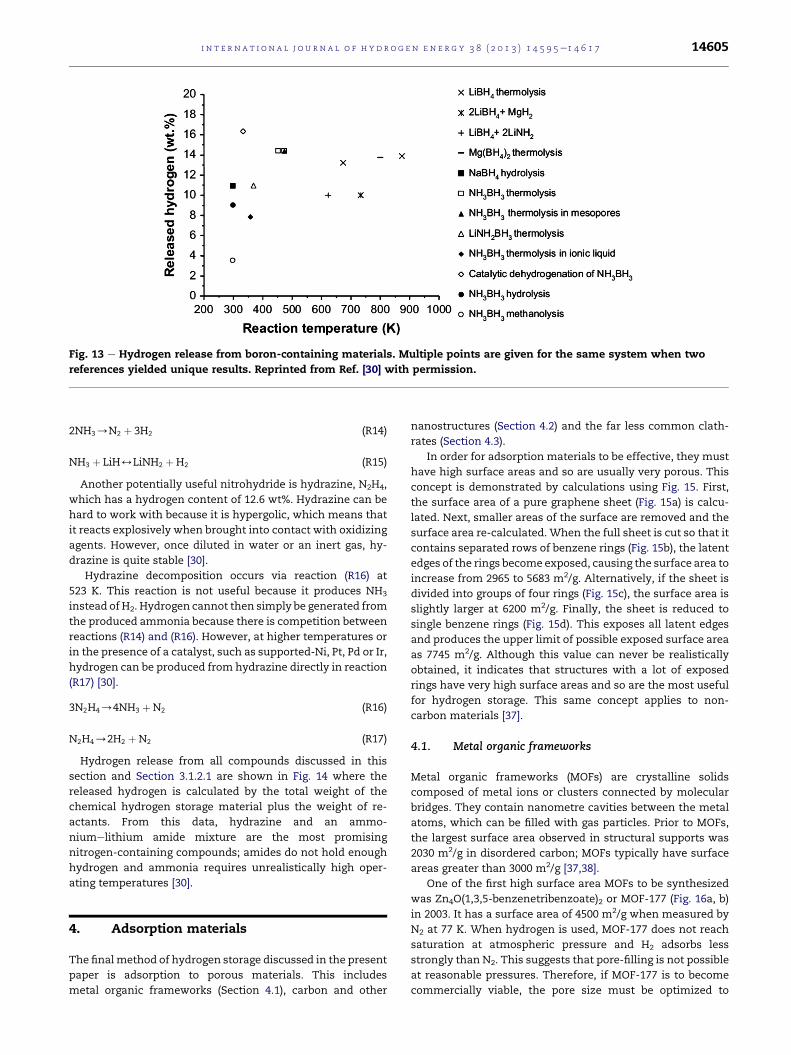
Fig. 13 e Hydrogen release from boron-containing materials. Multiple points are given for the same system when two
references yielded unique results. Reprinted from Ref. [30] with permission.
i n t e r n a t i o n a l j o u r n a l o f h y d r o g e n en e r g y 3 8 ( 2 0 1 3 ) 1 4 5 9 5e1 4 6 1 7 14605
2NH3/N2 þ 3H2 (R14)
NH3 þ LiH4LiNH2 þH2 (R15)
Another potentially useful nitrohydride is hydrazine, N2H4,
which has a hydrogen content of 12.6 wt%. Hydrazine can be
hard to work with because it is hypergolic, which means that
it reacts explosively when brought into contact with oxidizing
agents. However, once diluted in water or an inert gas, hy-
drazine is quite stable [30].
Hydrazine decomposition occurs via reaction (R16) at
523 K. This reaction is not useful because it produces NH3
instead of H2. Hydrogen cannot then simply be generated from
the produced ammonia because there is competition between
reactions (R14) and (R16). However, at higher temperatures or
in the presence of a catalyst, such as supported-Ni, Pt, Pd or Ir,
hydrogen can be produced from hydrazine directly in reaction
(R17) [30].
3N2H4/4NH3 þN2 (R16)
N2H4/2H2 þN2 (R17)
Hydrogen release from all compounds discussed in this
section and Section 3.1.2.1 are shown in Fig. 14 where the
released hydrogen is calculated by the total weight of the
chemical hydrogen storage material plus the weight of re-
actants. From this data, hydrazine and an ammo-
niumelithium amide mixture are the most promising
nitrogen-containing compounds; amides do not hold enough
hydrogen and ammonia requires unrealistically high oper-
ating temperatures [30].
4. Adsorption materials
The finalmethod of hydrogen storage discussed in the present
paper is adsorption to porous materials. This includes
metal organic frameworks (Section 4.1), carbon and other
nanostructures (Section 4.2) and the far less common clath-
rates (Section 4.3).
In order for adsorption materials to be effective, they must
have high surface areas and so are usually very porous. This
concept is demonstrated by calculations using Fig. 15. First,
the surface area of a pure graphene sheet (Fig. 15a) is calcu-
lated. Next, smaller areas of the surface are removed and the
surface area re-calculated. When the full sheet is cut so that it
contains separated rows of benzene rings (Fig. 15b), the latent
edges of the rings become exposed, causing the surface area to
increase from 2965 to 5683 m2/g. Alternatively, if the sheet is
divided into groups of four rings (Fig. 15c), the surface area is
slightly larger at 6200 m2/g. Finally, the sheet is reduced to
single benzene rings (Fig. 15d). This exposes all latent edges
and produces the upper limit of possible exposed surface area
as 7745 m2/g. Although this value can never be realistically
obtained, it indicates that structures with a lot of exposed
rings have very high surface areas and so are the most useful
for hydrogen storage. This same concept applies to non-
carbon materials [37].
4.1. Metal organic frameworks
Metal organic frameworks (MOFs) are crystalline solids
composed of metal ions or clusters connected by molecular
bridges. They contain nanometre cavities between the metal
atoms, which can be filled with gas particles. Prior to MOFs,
the largest surface area observed in structural supports was
2030 m2/g in disordered carbon; MOFs typically have surface
areas greater than 3000 m2/g [37,38].
One of the first high surface area MOFs to be synthesized
was Zn4O(1,3,5-benzenetribenzoate)2 or MOF-177 (Fig. 16a, b)
in 2003. It has a surface area of 4500 m2/g when measured by
N2 at 77 K. When hydrogen is used, MOF-177 does not reach
saturation at atmospheric pressure and H2 adsorbs less
strongly than N2. This suggests that pore-filling is not possible
at reasonable pressures. Therefore, if MOF-177 is to become
commercially viable, the pore size must be optimized to

Fig. 14 e Hydrogen release from nitrogen-containing hydrides. Multiple points are given for the same system when two
references yielded unique results. Reprinted from Ref. [30] with permission.
i n t e rn a t i o n a l j o u r n a l o f h y d r o g e n en e r g y 3 8 ( 2 0 1 3 ) 1 4 5 9 5e1 4 6 1 714606
reduce the fraction of under-utilized space; this will in turn
increase the volumetric capacity of the material [38].
The ideal pore size (shown as a yellow sphere in Fig. 16) for
maximum attraction of adsorbate to the MOF is the same as
the adsorbate’s van der Waal diameter. Ideal pores require
thin walls and so should be composed of light elements, one
atom thick and highly segmented. This requires short linking
groups between metal atoms. This is problematic because it
increases the gravimetric density of the material [38].
Another approach to increase the contactable surface area
within large pores is to insert another adsorbate molecule by
impregnating the MOF with a non-volatile guest. A guest re-
duces the diameter of the pores and provides additional
adsorption sites. An impregnation species must be chosen
carefully so that it does not add significant weight or block
existing adsorptive sites. In addition, the guest must have low
vapour pressure so that it is not desorbed during removal of
hydrogen. A reactive species would be ideal to increase
attraction of hydrogen to the MOF, but this is not always
possible. Buckminsterfullerene, C60, and Reichardt’s dye have
been shown to incorporate well into MOF-177 (Fig. 17). This is
shown with C60 in Fig. 16c [38].
A third option to decrease pore size in MOFs is catenation
with another identical framework. This can be done by
interpenetration, in which the frameworks are maximally
Fig. 15 e Surface area of graphene fragments used to calculate th
from Ref. [37] with permission.
displaced from each other (Fig. 18a), interweaving, where
there is minimal displacement (Fig. 18b), or a combination of
the two (Fig. 18c) [38].
The combination technique is most common because the
individual techniques have both advantages and disadvan-
tages. Interpenetration is more effective at maximizing
exposed surfaces than interweaving because it decreases pore
size without blocking adsorptive sites. Unfortunately, inter-
penetrated states are often unstable when the MOF is evacu-
ated. In contrast, interweaving reinforces the individual
frameworks and so improves the rigidity and stability of the
MOF in the absence of hydrogen. However, this also causes
thickening of the walls, which reduces the number of
adsorptive sites [38].
One way to increase the effectiveness of catenation is to
create open metal sites, which strengthens H2 physisorption.
This can be done by removing the axial ligands from the
inserted MOF (Fig. 19). This is possible if the ligand is weakly
bound to the metal and if the MOF maintains its shape after
the ligand is removed. Alternatively, open metal sites can be
created by embedding them within the linker. Removal of the
axial ligands is often favoured because it also decreases the
density of the framework [38].
Catenation has been shown to be effective in a study that
comparedMOF-177 (Fig. 18) and IRMOF-1, 8, 11 and 18 (Fig. 20).
e theoretical upper limit of possible surface area. Reprinted

Fig. 16 e Crystal structure of MOF-177 with C [ black, O [ red, Zn [ blue polyhedral; yellow spheres contact the van der
Waals radii of the framework atoms to indicate the pore volume. It is displayed as a single molecule (a), in a molecular group
(b) and impregnated with C60 (c). (For interpretation of the references to colour in this figure legend, the reader is referred to
the web version of this article.) Reprinted from Ref. [38] with permission.
i n t e r n a t i o n a l j o u r n a l o f h y d r o g e n en e r g y 3 8 ( 2 0 1 3 ) 1 4 5 9 5e1 4 6 1 7 14607
Although previous studies found that hydrogen had the
strongest interaction in IRMOF-1, a study involving catenation
showed that fourfold interwoven IRMOF-11 has the strongest
hydrogen uptake; it was able to absorb 1 wt% hydrogen at
room temperature and 47 atm [39].
Another important aspect to consider is the influence of
different metals. An effective metal must have good attrac-
tion to hydrogen and not add significant weight to the sys-
tem. Zinc is most commonly used, but light main group
elements, such as Li, Na, Mg and Al, have more desirable
weights. Unfortunately, the main group monovalent cations
are impractical because they make the MOF susceptible to
hydrolysis; main group multivalent cations have strong
polarizing power that should be useful for producing strong
coordination bonds, but they form oxides easily. For example,
an aluminium MOF, MIL-53 synthesized in the mid-2000’s,
had a good hydrogen adsorption capacity of 3.8 wt% at 77 K
and 15.8 atm, but it showed usually high hysteresis upon
desorption and so could not be used [38].
In addition to these main group elements, other transition
metals have been considered as well. For example, recent
work investigated the hydrogen storage capacity in iron MOFs
and found that a theoretical reversible hydrogen storage of
6.0 wt% was achieved at 298 K and 100 atm. Heterometallic
MOFs have also been studied. One example of a ceriumezinc
MOF, Ce(oda)3Zn1.5(H2O)3$0.75H2O, shows an experimental
reversible hydrogen storage of 1.34wt% at 77 K and 0.86wt% at
298 K and 33.5 atm [41,42].
Fig. 17 e Structure of Reichardt’s dye (left) and
buckminsterfullerene (right).
4.2. Nanostructures
4.2.1. Carbon materialsHydrogen adsorption on carbon nanomaterials is a relatively
new field because these structures have only been available in
the last few decades. Initial work began with carbon nano-
tubes (CNTs, Section 4.2.1.2) in the late 1990’s. Since then,
hydrogen adsorption on several different fullerenes and acti-
vated carbons has been studied [43].
Fig. 21 shows gravimetric hydrogen storage capacities on
many carbon nanofibres (Fig. 21a), nanotubes (Fig. 21b) and
activated carbons (Fig. 21c). The highest values occur on car-
bon nanofibres with 67.55 wt% on herringbone graphite
nanofibres and 53.68 wt% on platelet graphite nanofibres at
room temperature and 110 atm. The highest values for
nanotubes are 20 wt% for Li-doped CNTs and 14 wt% from K-
doped systems. No general trends are observed on either
carbon nanofibres or nanotubes and the extreme results are
not reproducible. In contrast, for activated carbons, a repro-
ducible general trend shows that hydrogen adsorption in-
creases with decreasing temperature and increasing pressure.
However, the highest hydrogen storage is only 5 wt% on AC-21
at 77 K and 30e60 atm [43].
4.2.1.1. Activated carbon. Activated carbons were one of the
first carbon materials considered for hydrogen storage.
Although, they cannot hold as much H2 as other carbon ma-
terials, they are desirable because they can be easily produced
and their chemistry is relatively well understood [43].
In general, the gravimetric hydrogen capacity of activated
carbons is correlated with the amount and distribution of
porosity in thematerial. A highmicropore volume and narrow
size range leads to the highest hydrogen uptake. However, at
lower temperatures the material becomes more absorbent so
the micropore size distribution is less important [43].
One of the most effective activated carbons is KUA5. At
room temperature, it absorbs 3.2wt%hydrogen at 187 atm and
6.8 wt% at 493 atm; at 77 K, it absorbs 8 wt% at only 39 atm.
This suggests that activated carbons can be effective for
hydrogen storage, but only at low temperatures. However, a
recent study of another activated carbon, AX-21, found that

Fig. 18 e Schematic representation of MOFs depicted as cubes and rods showing catenation by interpenetration (left),
interweaving (centre) and a combination (right) where the yellow sphere indicates the pore volume. (For interpretation of
the references to colour in this figure legend, the reader is referred to the web version of this article.) Reprinted from Ref. [38]
with permission.
i n t e rn a t i o n a l j o u r n a l o f h y d r o g e n en e r g y 3 8 ( 2 0 1 3 ) 1 4 5 9 5e1 4 6 1 714608
even cryogenic storage is difficult. AX-21 was previously
shown to have a relatively high hydrogen storage capacity of
5.4 wt% at 77 K, but the recent cryogenic study found that at
100 K, it does not enhance the hydrogen storage capacity
above that of the non-adsorbed cryocompressed gas. In
addition, more than 80% of the sorption capacity is irrecov-
erable at 99 atm and 100 K. Finally, 11 kWh of electricity are
required per kilogram of dispensed H2 if off-board liquid N2 is
used to cool the gas. Therefore, refuelling is energy-expensive
[43,46].
Cryogenic storage is also difficult because the tankmust be
cooled. This can be accomplished by surrounding it with
vacuum insulation and having minimal conduction paths to
the ambient atmosphere. This increases the volume and cost
of the system. In addition, the small amount of heat generated
when hydrogen adsorbs to the carbon surface must be
removed when the tank is refuelled. Heat transfer is difficult
for any cryogenic systems and is especially difficult for cryo-
adsorption because activated carbons have low thermal con-
ductivity. Finally, a temperature swing is usually required to
desorb the H2 gas, which makes the system design more
complicated, larger and more costly [44].
4.2.1.2. Carbon nanotubes. Carbon nanotubes (CNTs) were the
first carbon material considered for hydrogen storage in 1997
because they have a microporous structure with high specific
surface area. In addition, CNTs can adsorb hydrogen onto the
interior and exterior of their nanostructure. This leads to
Fig. 19 e Example of removing the axial H2O ligands from
the Cu(II) carboxylate “paddlewheel” cluster MOF.
Reprinted from Ref. [38] with permission.
storage capacities of 0.25e11 wt% hydrogen under varying
conditions. When metals are added to the systems (Section
4.2.1.4), the gravimetric capacity increases to 1.8 to 20 wt%.
The variation in these results can be effected by defects in the
CNTs and open versus closed structures [45].
In order to better understand how much H2 can be held in
each class of CNTs, a recent study looked at single-, double-
and tripled-walled CNTs and a bundle of single-walled car-
bon nanotubes (SWCNTs). These classes were then sub-
divided according to size where the smallest tubes
experience fracture in order to meet the DOE targets; medium
tubes experience strain; large tubes are not affected; and
extra-large tubes self-collapse upon hydrogen release. The
chirality and radii of each class of CNTs required to meet the
2010 DOE targets (6 wt% H2, 62 kg H2/m3) are shown in Table 2
[45].
These results suggest that large-sized single- (alone or in a
bundle) and double-walled CNTs can meet the DOE hydrogen
storage goals. Smaller and larger nanotubes can meet the
targets theoretically, but they are damaged in the process and
so are not reusable. This is especially true for the small and
extra-large nanotubes [45].
A furtherMonte Carlo study looked into a largely unstudied
aspect of carbon nanotubes e packing in 3D covalent assem-
blies. These are different than the nanotube bundles
mentioned in Table 2, in which the CNTs are joined by van der
Waals forces. In order to model realistic packed structures,
which are likely tangled, a 3-periodic arrangement of nano-
tubes with three or four different orientations of tube axes
were modelled (Fig. 22) [46].
The simulated structures were found to have very high
hydrogen uptakes up to 19 wt% at 99 atm and 77 K. These are
the highest hydrogen storage capacities observed for non-
decorated nanotubes. At room temperature, the storage ca-
pacity remained acceptably high at 5.5 wt%. This approaches
the 2010 DOE target of 6 wt%. The study also found that
hydrogen uptake ability was mainly determined by the nano-
tube arrangement in space and was almost independent of
tube size. Furthermore, H2 uptake increased proportionally to
pore volume at room temperature, but at 77 K, there was an
optimal pore size after which hydrogen uptake remained
steady [46].
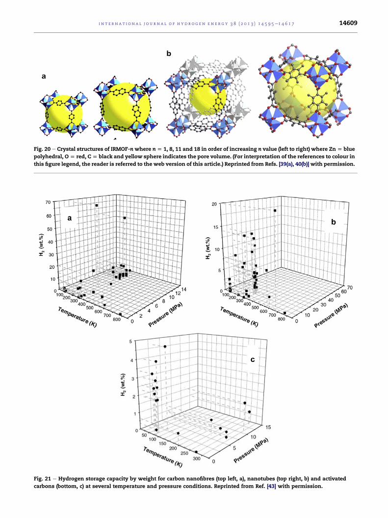
Fig. 20 e Crystal structures of IRMOF-nwhere n[ 1, 8, 11 and 18 in order of increasing n value (left to right) where Zn[ blue
polyhedral, O[ red, C[ black and yellow sphere indicates the pore volume. (For interpretation of the references to colour in
this figure legend, the reader is referred to the web version of this article.) Reprinted from Refs. [39(a), 40(b)] with permission.
Fig. 21 e Hydrogen storage capacity by weight for carbon nanofibres (top left, a), nanotubes (top right, b) and activated
carbons (bottom, c) at several temperature and pressure conditions. Reprinted from Ref. [43] with permission.
i n t e r n a t i o n a l j o u r n a l o f h y d r o g e n en e r g y 3 8 ( 2 0 1 3 ) 1 4 5 9 5e1 4 6 1 7 14609

Table 2 e Ranges of chirality and radii of several classes of carbon nanotubes required to meet DOE 2010 hydrogen storagetargets.
Type of CNT Reaction to hydrogen release
Fracture (small) Strain (medium) No effect (large) Self-collapse (extra large)
Single-walled (7,7) and down
<0.47 nm
(8,8) to (18,18)
0.54e1.2 nm
(19,19) to (30,30)
1.3e2.0 nm
(31,31) and up
>2.1 nm
Double-walled (11,11) and down
<0.75 nm
(12,12) to (31,31)
0.81e0.21 nm
(32,32) to (36,36)
2.2e2.4 nm
(37,37) and up
>2.5 nm
Triple-walled (16,16) and down
<1.1 nm
(17,17) to (41,41)
1.2e2.8 nm
Not possible (42,42) and up
>2.8 nm
Bundle of SWCNTs (7,7) and down
<0.47 nm
(8,8) to (21,21)
0.54e1.4 nm
(22,22) to (30,30)
1.5e2.0 nm
(31,31) and up
>2.1 nm
Reprinted from Ref. [45] with permission.
i n t e rn a t i o n a l j o u r n a l o f h y d r o g e n en e r g y 3 8 ( 2 0 1 3 ) 1 4 5 9 5e1 4 6 1 714610
When the mechanism of hydrogen adsorption was more
closely examined at multiple pressures, it was found that at a
low pressure of 0.1 atm, adsorption is primarily observed at
the sites where the H2 molecules can simultaneously come
close to the surfaces of several nanotubes. This leads to
minimal hydrogen accumulation in the centre of the pore
(Fig. 23a). As the pressure was increased to 1.0 atm, more H2
molecules began to cover the external surface of the tubes
(Fig. 23b) until they eventually filled the centre of the pore at
99 atm (Fig. 23c) to produce a saturated material [46].
In the case of small tubes, no hydrogenwas adsorbed to the
interior of the tube; in larger nanotubes, H2 molecules formed
a narrow chain along the tube axis. This suggests that as-
semblies of larger tubes will have the best storage properties.
This research is ongoing [46].
Fig. 22 e Covalent carbon nanotube systems modelled to analyz
from Ref. [46] with permission.
4.2.1.3. Spherical fullerenes. The potential hydrogen storage
ability of the most common spherical fullerene, buckmin-
sterfullerene, C60, was predicted in 1991 when it was deter-
mined that an H2 molecule can be trapped within a C60 cage.
Although it is usually unfavourable for hydrogen to be stored
in such a space, the high energy barrier required to break the
cage open stabilizes the H2 inside. It was later found that
buckminsterfullerene containing one H2 molecule can be
synthesized experimentally with high yield by molecular
surgery or by surrounding C60 cages with high pressure
hydrogen then using laser excitation [47].
Putting larger amountsofH2 into fullerene cages is currently
very experimentally difficult. Therefore, many problems must
be answered theoretically before the task can be undertaken.
These include how hydrogen is put inside the cage; how H2 is
e the effect of packing in 3D covalent assemblies. Reprinted
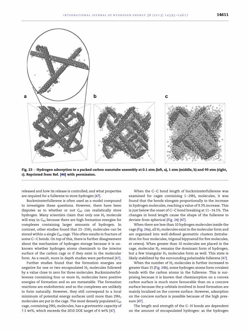
Fig. 23 e Hydrogen adsorption to a packed carbon nanotube assembly at 0.1 atm (left, a), 1 atm (middle, b) and 99 atm (right,
c). Reprinted from Ref. [46] with permission.
i n t e r n a t i o n a l j o u r n a l o f h y d r o g e n en e r g y 3 8 ( 2 0 1 3 ) 1 4 5 9 5e1 4 6 1 7 14611
released and how its release is controlled; and what properties
are required for a fullerene to store hydrogen [47].
Buckminsterfullerene is often used as a model compound
to investigate these questions. However, there have been
disputes as to whether or not C60 can realistically store
hydrogen. Many scientists claim that only one H2 molecule
will stay in C60 because there are high formation energies for
complexes containing larger amounts of hydrogen. In
contrast, other studies found that 23e25H2 molecules can be
storedwithin a single C60 cage. This often results in fracture of
some CeC bonds. On top of this, there is further disagreement
about the mechanism of hydrogen storage because it is un-
known whether hydrogen atoms chemisorb to the interior
surface of the carbon cage or if they exist in the molecular
form. As a result, more in depth studies were performed [47].
Further studies found that the formation energies are
negative for one or two encapsulated H2 molecules followed
by a value close to zero for three molecules. Buckminsterful-
lerenes containing four or more H2 molecules have positive
energies of formation and so are metastable. The formation
reactions are endothermic and so the complexes are unlikely
to form naturally. However, they still correspond to a local
minimum of potential energy surfaces until more than 29H2
molecules are put in the cage. Themost densely populated C60
cage, containing 29H2 molecules, has a gravimetric capacity of
7.5 wt%, which exceeds the 2010 DOE target of 6 wt% [47].
When the CeC bond length of buckminsterfullerene was
examined for cages containing 1e29H2 molecules, it was
found that the bonds elongate proportionally to the increase
in hydrogenmolecules, reaching a value of 9.3% increase. This
is just below the onset of CeC bond breaking at 11e14.5%. The
changes in bond length cause the shape of the fullerene to
deviate from spherical (Fig. 24) [47].
When there are less than 10 hydrogenmolecules inside the
cage (Fig. 24a), all H2molecules exist in themolecular formand
are organized into well-defined geometric clusters (tetrahe-
dron for fourmolecules, trigonal bipyramid for fivemolecules,
et cetera). When greater than 10 molecules are placed in the
cage, molecular H2 remains the dominant form of hydrogen,
but a few triangular H3 molecules form as well. This state is
likely stabilized by the surrounding polarizable fullerene [47].
When the number of H2 molecules is further increased to
greater than 15 (Fig. 24b), some hydrogen atoms form covalent
bonds with the carbon atoms in the fullerene. This is sur-
prising because it is known that chemisorption on a convex
carbon surface is much more favourable than on a concave
surface because the p-orbitals involved in bond formation are
mainly localized on the convex surface. However, adsorption
on the concave surface is possible because of the high pres-
sure [47].
The length and strength of the CeH bonds are dependent
on the amount of encapsulated hydrogen: as the hydrogen

Fig. 24 e C60 containing 5 (left, a), 15 (middle, b) and 25 (right, c) H2 molecules showing the deformation of the fullerene and
the formation of H3 and covalently bound hydrogen. Reprinted from Ref. [47] with permission.
i n t e rn a t i o n a l j o u r n a l o f h y d r o g e n en e r g y 3 8 ( 2 0 1 3 ) 1 4 5 9 5e1 4 6 1 714612
pressure increases, the CeH bond length decreases. However,
the bond length increases again when more than 24H2 mole-
cules are present in the cage (Fig. 24c) so that H/H2 van der
Waals interactions can occur. When CeH bonds are formed,
the C60 structure becomes deformed in order to produce more
sp3-hybridized carbon atoms that are able to bond hydrogen.
This causes the surface to become flattened near the CeH
bonds and so the fullerene has increased curvature elsewhere.
The sp3-hybridized carbon atoms no longer contribute to the
fullerene’s conjugated p-system so the cage is weakened [47].
If more hydrogen is placed in the system, the fullerene will
eventually break open. This is initiated by the breaking of a
CeC bond involving one carbon that is bound to a hydrogen
atom and one that is not. When the non-hydrogenated carbon
is completely surrounded by partially hydrogenated carbon
atoms, there is nowhere for its p-electron density to go.
Therefore, one of its CeC bonds breaks, causing the neigh-
bouring carbon to become fully hydrogenated and the initial
carbon to become a radical. The hydrogen atoms then shift
position to restore the sp2 character of the carbons while in-
ternal pressure pushes the remaining hydrogen towards the
opening. Due to the hydrogenation of the terminating carbon
atoms, the process is irreversible. This is shown in Fig. 25 with
the bond that breaks highlighted in black [47].
Regardless of its uptake and release mechanisms, putting
H2 in a fullerene is still largely unfavourable. Therefore, many
methods of fullerenes enhancement have been investigated.
One option is to charge the fullerene. This can be done by
electrochemical doping, ion/electron impact, laser desorption
or chemical doping. Electrochemical doping has been
Fig. 25 e Cage opening and hydrogen escape from a C60 contain
black. Images were obtained by ab initio molecular dynamics si
from Ref. [47] with permission.
experimentally shown to form fullerene anions and cations in
solution with irreversible charges up to �6; ion/electron
bombardment or laser deposition produce fullerene ions in
the gas phase; chemical doping has not been extensively
studied at this point, but it should produce fullerenes with
even higher charges. Chemical doping can be done through
substitutional, endohedral or exohedral doping of the
fullerene with metal atoms (Section 4.2.1.4) [48].
When density functional theory studies analyzed the
storage ability of charged fullerenes, the hydrogen binding
energy was found to be favourable at 0.18e0.32 eV. This is
within the DOE desired range of 0.2e0.6 eV. Within this range,
H2 can adsorb and desorb under near ambient conditions. The
study further found that hydrogen binding is delocalized and
so surrounds the entire surface of the charged fullerene. This
binding is attributed to polarization of H2 molecules by the
electric field near the fullerene surface [48] (Yoon, 2007).
Charged fullerenes have a potential hydrogen storage ca-
pacity of 8.0 wt%. Fullerenes containing an endohedral metal
atom did not show a significant enhancement to hydrogen
binding but systems containing exohedral metal atoms are
quite promising [48]. These are further discussed in Section
4.2.1.4.
4.2.1.4. Metal-decorated carbons. One method used to in-
crease the hydrogen storage capacity of carbon materials at
ambient conditions is combination with metal. This can be
done through physical mixing or chemical doping of the car-
bon surface. Physical mixing is affected by sample concen-
tration, grinding time and intensity and contacts between
ing 29H2 molecules. The bond that breaks is highlighted in
mulations at 0, 250, 350 and 800 fs respectively. Reprinted

Fig. 26 e Diagram of hydrogen spillover on platinum-
decorated carbon nanotubes (CNTs). Reprinted from Ref.
[51] with permission.
i n t e r n a t i o n a l j o u r n a l o f h y d r o g e n en e r g y 3 8 ( 2 0 1 3 ) 1 4 5 9 5e1 4 6 1 7 14613
particles. Therefore, samples are often difficult to reproduce.
Chemical doping requires less metal and so is less expensive
and more reproducible [49]. It will be the focus of this section.
Carbon decoration with metal nanoparticles has proved
very effective in recent years and so is being givenconsiderable
attention.Onecurrentproject investigateshydrogenstorage in
platinum-decorated fullerenes [50].
Hydrogen storage on metal-decorated carbons occurs by
spillover (Fig. 26). Hydrogen spillover is the process of H2
dissociative chemisorption on metal nanoparticles followed
by migration of the hydrogen atoms onto adjacent surface
sites [49].
The storage capacity of a metal-decorated carbon material
can be enhanced by three factors: (i) identity of the doping
metal; this is usually Pt or Pd, although other metals are used;
(ii) surface area of the carbon material; (iii) contact between
the carbon surface and metal nanoparticles; this is important
because large physical and energetic barriers often exist for
the transfer of hydrogen atoms from one material to another
so close metalecarbon contact is needed [49].
Fig. 27 e C60 decorated with eight sodium atoms in the absence
from Ref. [55] with permission.
Many studies have looked into optimizing these factors.
Since this is a relatively young field, no conclusive results have
yet been determined. Therefore, a small sample of studies is
provided in this paper as examples of the current research e
several different metals and carbon materials are presented
through a mixture of experimental and theoretical results.
Procedures and mechanisms are not discussed.
One interesting experimental project compared ruthe-
nium, platinum and nickel on templated carbon (TC). It found
that Ru is the most effective metal for hydrogen dissociation
with the Ru-TC system showing a storage capacity of 1.43 wt%
at 298 K and 102 atm. When a direct high-temperature ther-
mal reduction was used to increase contact between Ru and
the carbon support, the treated sample had an even higher
hydrogen storage capacity of 1.56 wt%. Similar positive results
were observed in another study analyzing Pt-decorated AX-21
activated carbon. This study found that the reversible
hydrogen storage capacity of 0.6 wt% on AX-21 was increased
to 1.2 wt% on Pt/AX-21 at 298 K and 99 atm [49,52].
Similar studies have investigated metal-decorated carbon
nanotubes (CNTs). In one such project, first principles calcu-
lations found that a single titanium atom adsorbed on the
surface of a single-walled carbon nanotube (SWCNT) strongly
bond up to four H2 molecules. This would allow the system to
hold 8 wt% hydrogen [53].
Experimental results have not been as favourable. A recent
study compared palladium and vanadium-decorated SWCNTs
with undecorated treated nanotubes. It found that, although the
metal-decorated CNTs showed a higher hydrogen uptake than
the untreated nanotubes at room temperature, all systems had
very low hydrogen adsorptions of 0.125 wt% on Pd-CNTs and
0.1 wt% on V-CNTs. In a second cycle, only half of the initial
hydrogen uptake was obtained. This change was caused by the
recrystallization of the defect sites, which are a large source for
accepting dissociated hydrogen atoms. In addition, defect
recrystallization also caused a decrease in the interaction be-
tween themetal andcarbonsupport,which limited theability for
spillover.Asa result, hydrogenuptake in the secondcyclemostly
resulted from H2 adsorption to the metal surface directly [54].
Metal-decorated spherical fullerenes have also been stud-
ied. Recent ab initio projects analyzed the effect of C60
(left, A) and presence (right, B) of H2 molecules. Reprinted

Fig. 28 e Equivalent carbon and boron nitride (BN) nanomaterials where C [ grey, B [ blue and N [ yellow. The carbon
structures displayed are a carbon nanotube (CNT) (top left), graphene sheet (bottom) and graphene nanoribbon (GNR) (top
right). The BN equivalents are a boron nitrogen nanotube (BNNT), hexagonal boron nitrogen sheet (h-BN) and boron nitrogen
nanoribbon (BNNR) respectively. (For interpretation of the references to colour in this figure legend, the reader is referred to
the web version of this article.) Reprinted from Ref. [56] with permission.
i n t e rn a t i o n a l j o u r n a l o f h y d r o g e n en e r g y 3 8 ( 2 0 1 3 ) 1 4 5 9 5e1 4 6 1 714614
decoration with alkali metals. These studies found that
doping with alkali metals increased the hydrogen adsorption
ability of the fullerene by more than traditional transition
metals. The most effective system involved sodium where 48
H2 molecules adsorbed to eight sodium atoms corresponding
to a hydrogen storage capacity of 9.5 wt%. This high hydrogen
adsorption seems to be a result of ion-molecule electrostatic
interactions because it was found that a large number of
hydrogenmolecules surround themetal ions (Fig. 27). This is a
contrast to the hydrogen spillover mechanism observed with
transition metals (Fig. 26) [55].
4.2.2. Other nanostructure materialsWhile the focus of hydrogen storage in nanomaterials has
centred on carbon materials, there are other nanostructures
worth considering. Most of these have a large contribution
from boron. Two classes worth mentioning are boron fuller-
enes, which have identical composition to carbon fullerenes,
Fig. 29 e Calcium-decorated boron fullerenes storing five H2 mo
nanotube (right, b) with B [ pink, Ca [ green and H [ white.
legend, the reader is referred to the web version of this article.
but are composed of boron atoms instead of carbon atoms,
and boron nitride (BN) nanostructures, which have similar
geometries to carbon nanostructures, but with alternating
boron and nitrogen atoms instead of carbon (Fig. 28). Although
the structure of these materials is very similar to that of car-
bonmaterials, they can have quite different properties [56,57].
One density functional theory study performed on
calcium-decorated boron fullerenes found that the decorating
calcium atoms can attract five H2 molecules each. Given this,
the modelled B80 system decorated with 12 calcium atoms
(Fig. 29a) had a gravimetric density of 8.2 wt% hydrogen with
favourable binding energies of 0.12e0.40 eV/H2. Similarly, a
Ca-decorated boron nanotube (Fig. 29b) had a hydrogen stor-
age capacity of 7.6 wt% with binding energies of 0.10e0.30 eV/
H2. Most importantly, adsorption and desorption of these H2
molecules was favourable at ambient conditions. These re-
sults are very promising, but they have not yet been repro-
duced experimentally [57].
lecules per calcium atom showing B80 (left, a) and a boron
(For interpretation of the references to colour in this figure
) Reprinted from Ref. [57] with permission.

Table 3 e Hydrogen storage capacity and requiredpressure of several clathrates (tabulated using data fromRef. [59]).
Cagematerial
Solid:gasratio
Hydrogen storagecapacity (g/L H2)
Requiredpressure (atm)
H2O 1:6 23 6900
1:1 110 21,700
CH4 2:1 Not measured 44,400e79,000
1:1
1:2
1:4
i n t e r n a t i o n a l j o u r n a l o f h y d r o g e n en e r g y 3 8 ( 2 0 1 3 ) 1 4 5 9 5e1 4 6 1 7 14615
An experimental study analyzing boron-nitrogenmaterials
found that an h-BN structure stored 2.6 wt% hydrogen at high
temperature and pressure; the equivalent carbon structure
(graphite) stored 7.4 wt%. This puts the BN material at a
disadvantage relative to the carbon equivalent. However, h-BN
desorbs H2 at a temperature 30 K lower than graphite, which is
a large asset. Research into non-carbon nanostructures is
ongoing [58].
4.3. Clathrates
The final hydrogen adsorption system discussed in this paper
is clathrates. Clathrates are chemical compounds consisting
of a lattice of one compound trapping a second compound.
Water (H2O) is the most common lattice material (producing a
clathrate hydrate)with the nextmost common beingmethane
(Fig. 30). Ammonia, carbon dioxide and several other com-
pounds are also possible clathrates [36,59,60].
Several gas-filled water and methane clathrates were
synthesized in the late 1990’s; they are described in Table 3. As
can be seen, these clathrates can hold large amounts of
hydrogen, but they require very high pressures. Therefore, in
the early 2000’s clathrates were studied again with low tem-
peratures (77e300 K) used to form the lattice instead of high
pressures [59].
This project showed some success with H2(H2O)2, H2(H2O)
and (H2)4(CH4), which store 5.3, 11.2 and 33.4 wt% hydrogen
respectively. This is above the 2015 DOE target of 9 wt% for
H2(H2O) and (H2)4(CH4). The same trend was observed with
gravimetric capacities of 1.8, 3.7 and 11.1 kW h/kg respec-
tively. These are above the 2015 target of 3 kW h/kg for
H2(H2O) and (H2)4(CH4). Finally, the volumetric capacities
were found to be 1.5, 3.5 and 10 kW h/L respectively. Again,
these are above the 2015 target of 2.7 kW h/L for H2(H2O) and
(H2)4(CH4); the capacity is equal to the 2010 target for
H2(H2O)2 [59].
These values appear promising, but they only occur at very
high pressures and at least 2467 atm is required for synthesis.
In addition, the use of methane is undesirable because one of
the main reasons for switching to hydrogen fuel is to prevent
further use of fossil fuels in energy production. Therefore,
Fig. 30 e Crystal structure of CH4(H2)2 (left) and (CH4)2H2
(right) with the CH4 groups represented as blue balls and
the H2 groups represented as red balls. (For interpretation
of the references to colour in this figure legend, the reader
is referred to the web version of this article.) Reprinted
from Ref. [60] with permission.
only hydrogen hydrates were studied further. These studies
found that hydrogen hydrates have a theoretical storage
capacity of 5.6 wt% hydrogen at 59e118 atm and 263 K with
low energy H2 storage and release processes. The hydrogen
release energy, which is the energy required to decompose the
hydrate lattice (heat of fusion), can be obtained from waste
heat. In addition, hydrates have advantages in terms of cost,
safety and environmental impact: hydrogen hydrates will not
explode because they are self-extinguishing; they are low cost
because the main component is water and sea water can be
used; they are environmentally friendly because disposal
costs are negligible. Unfortunately, they still require very high
pressures for synthesis and operate at temperatures below the
freezing point of water [36,59].
5. Conclusion
The present paper discussed hydrogen gas storage methods
from the last several decades. H2 storage has become very
important in recent years because fossil fuel resources are
diminishing and the environmental harms associated with
their burning are now undeniably apparent. A clean, abun-
dant, reliable replacement is needed. Hydrogen is a good en-
ergy storage molecule, but it can only be used if H2
containment and transportation are properly developed. The
general categories of hydrogen storage discussed in this paper
include mechanical techniques, such as cooling and com-
pressing of the gas, chemical hydrides, which contain
hydrogen chemically bonded to non-hydrogen atoms, and
adsorption materials, which include metal-organic frame-
works, carbon and other nanostructures, and clathrates.
These techniques are at various stages in their development
and show a wide range of gravimetric and volumetric
hydrogen storage capacities. There are many encouraging
theoretical results, but an experimental system capable of
meeting the targets set out by the U.S. Department of Energy
has not yet been found. Therefore, extensive research in this
field continues.
r e f e r e n c e s
[1] Hoel M, Kverndokk S. Depletion of fossil fuels and theimpacts of global warming. Resources and Energy Ecomonics1996;18:115e36.

i n t e rn a t i o n a l j o u r n a l o f h y d r o g e n en e r g y 3 8 ( 2 0 1 3 ) 1 4 5 9 5e1 4 6 1 714616
[2] Solomon S, Plattner G-K, Knuttic R, Friedlingstein P.Irreversible climate change due to carbon dioxide emissions.Proceedings of the National Academy of Sciences of theUnited States of America 2008;106(6):1704e9.
[3] Jorgensen SW. Hydrogen storage tanks for vehicles: Recentprogress and current status. Current Opinion in Solid Stateand Materials Science 2011;15(2):39e43.
[4] Demirel Y. Energy production, conversion, storage,conservation, and coupling. In: Series: green energy andtechnology. Springer; 2012.
[5] Khan TI, Monde M, Setoguchi T. Hydrogen gas filling into anactual tank at high pressure and optimization of its thermalcharacteristics. Journal of Thermal Science2009;18(3):235e40.
[6] Eberhardt JJ. Fuels of the future for cars and trucks. Energyefficiency and renewable energy. In: Diesel Engine EmissionsReduction (DEER) workshop San Diego, California. U.S.Department of Energy; 2002.
[7] Hua TQ, Ahluwalia RK, Peng J-K, Kromer M, Lasher S,McKenney K, et al. Technical assessment of compressedhydrogen storage tank systems for automotive applications.International Journal of Hydrogen Energy 2011;36(4):3037e49.
[8] Satyapal S, Petrovic J, Read C, Thomas G, Ordaz G. The U.S.Department of energy’s national hydrogen storage project:progress towards meeting hydrogen-powered vehiclerequirements. Catalysis Today 2007;120(3e4):246e56.
[9] Aceves SM, Espinosa-Loza F, Ledesma-Orozco E, Ross TO,Weisberg AH, Brunner TC, et al. High-density automotivehydrogen storage with cryogenic capable pressure vessels.International Journal of Hydrogen Energy 2010;35(3):1219e26.
[10] Zheng J, Bie H, Xu P, Chen H, Liu P, Li X, et al. Experimentaland numerical studies on the bonfire test of high-pressurehydrogen storage vessels. International Journal of HydrogenEnergy 2010;35(15):8191e8.
[11] Xu P, Zheng J, Chen H, Liu P. Optimal design of high pressurehydrogen storage vessel using an adaptive genetic algorithm.International Journal of Hydrogen Energy 2010;35(7):2840e6.
[12] Doyoyo M, Faurem M. Pressure vessels with reinforcingspace-filling skeletons. Journal of Pressure VesselTechnology 2008;130(3):031210.
[13] Wolf J. Liquid-hydrogen technology for vehicles. MRSBulletin 2002;(September):684e7.
[14] Arnold G, Wolf J. Liquid hydrogen for automotive application:next generation fuel for FC and ICE vehicles. Teion Kogaku(Journal of the Cryogenic Society of Japan) 2005;40(6):221e30.
[15] Bossel U, Eliasson B, Taylor G. The future of the hydrogeneconomy: bright or bleak? Journal of KONES 2004;11(1-2):87e111.
[16] Crabtree GW, Dresselhaus MS, Buchanan MV. The hydrogeneconomy. Physics Today 2004;57(12):39e45.
[17] Ahluwalia RK, Hua TQ, Peng J-K, Lasher S, McKenney K,Sinha J, et al. Technical assessment of cryo-compressedhydrogen storage tank systems for automotive applications.International Journal of Hydrogen Energy 2010;35(9):4171e84.
[18] Paggiaro R, Benard P, Polifke W. Cryo-adsorptive hydrogenstorage on activated carbon. I: Thermodynamic analysis ofadsorption vessels and comparison with liquid andcompressed gas hydrogen storage. International Journal ofHydrogen Energy 2010;35:638e47.
[19] Weinberger B, Lamari FD. High pressure cryo-storage ofhydrogen by adsorption at 77 K and up to 50 MPa.International Journal of Hydrogen Energy 2009;34:3058e64.
[20] Aaradahl CL, Rassat SD. Overview of systems considerationsfor on-board chemical hydrogen storage. InternationalJournal of Hydrogen Energy 2009;34(16):6676e83.
[21] Gandhi K, Kumar Dixit D, Kumar Dixit B. Hydrogendesorption energies of Aluminum hydride (AlnH3n) clusters.Physica B: Condensed Matter 2010;405(15):3075e81.
[22] Jain IP, Lal C, Jian A. Hydrogen storage in Mg: A mostpromising material. International Journal of HydrogenEnergy 2010;35:5133e44.
[23] Jain IP, Jain P, Jian A. Novel hydrogen storage materials: areview of lightweight complex hydrides. Journal of Alloysand Compounds 2010;503(2):303e39.
[24] Ma Z, Chou MY. First-principles investigation of sodium andlithium alloyed alanates. Journal of Alloys and Compounds2009;479:1e2.
[25] Askri F, Ben Salah M, Jemni A, Ben Nasrallah S. Heat andmass transfer studies on metal-hydrogen reactor filled withMmNi4.6Fe0.4. International Journal of Hydrogen Energy2009;34(16):6705e11.
[26] Yoo J-H, Shim G, Park C-N, Kim W-B, Cho S-W. Influence ofMn or Mn plus Fe on the hydrogen storage properties of theTieCreV alloy. International Journal of Hydrogen Energy2009;34(22):9116e21.
[27] Xiangqian S, Yungui C, Mingda T, Chaoling W, Gang D,Zhenzhen K. The structure and high-temperature (333 K)electrochemical performance of La0.8�xCexMg0.2Ni3.5 (x ¼0.00e0.20) hydrogen storage alloys. International Journal ofHydrogen Energy 2009;34(8):3395e403.
[28] Ohoyama K, Nakamori Y, Orimo S, Yamada K. Revisedcrystal structure model of Li2NH by neutron powderdiffraction. Journal of the Physical Society of Japan2005;74:483e7.
[29] Wang Q, Chen Y, Gai J, Wu C, Tao M. Role of amino anion inmetal amides/imides for hydrogen storage: a first principleStudy. Journal of Physical Chemistry C 2008;112:18264.
[30] Umegaki T, Yan J-M, Zhang X-B, Shioyama H, Kuriyama N,Xu Q. Boron- and nitrogen-based chemical hydrogen storagematerials. International Journal of Hydrogen Energy2009;34(5):2303e11.
[31] Miwa K, Ohba N, Towata S, Nakamori Y, Orimo S. First-principles study on lithium borohydride LiBH4. PhysicalReview B 2004;69:245120.
[32] Moyses Araujo C, Blomqvist A, Ahuja R. Ti-induceddestabilization of NaBH4 from first-principles theory. Journalof Physics: Condensed Matter 2008;20(12):122202e5.
[33] Cheekatamarla PK, Finnerty CM. Reforming catalysts forhydrogen generation in fuel cell applications. Journal ofPower Sources 2006;160(1):490e9.
[34] Newson E, Truong TB. Low-temperature catalytic partialoxidation of hydrocarbons (C1eC10) for hydrogenproduction. International Journal of Hydrogen Energy2003;28(12):1379e86.
[35] Al-Kukhun A, Hwang HT, Varma A. A comparison ofammonia borane dehydrogenation methods for proton-exchange-membrane fuel cell vehicles: hydrogen yield andammonia formation and its removal. Industrial &Engineering Chemistry Research 2011;50:8824e35.
[36] Di Profio P, Arca S, Rossi F, Filipponi M. Comparison ofhydrogen hydrates with existing hydrogen storagetechnologies: Energetic and economic evaluations.International Journal of Hydrogen Energy2009;34(22):9173e80.
[37] Chae HK, Siberio-Perez DY, Kim J, Go YB, Eddaoudi M,Matzger AJ, et al. A route to high surface area, porosity andinclusion of large molecules in crystals. Nature2004;427(6974):523e7.
[38] Rowsell JLC, Yaghi OM. Strategies for hydrogen storage inmetal-organic frameworks. Angewandte ChemieInternational Edition 2005;44(30):4670e9.
[39] Rowsell JLC, Millward AR, Park KS, Yaghi OM. Hydrogensorption in functionalized metal-organic frameworks.Journal of the American Chemical Society 2004;126:5666.
[40] Eddaoudi M, Kim J, Rosi N, Vodak D, Wachter J, O’Keeffe M,et al. Systematic design of pore size and functionality in

i n t e r n a t i o n a l j o u r n a l o f h y d r o g e n en e r g y 3 8 ( 2 0 1 3 ) 1 4 5 9 5e1 4 6 1 7 14617
isoreticular MOFs and their application in methane storage.Science 2002;295(5554):469e72.
[41] Cha M-H, Nguyen MC, Lee Y-L, Im J, Ihm J. Iron-decorated,functionalized metal organic framework for high-capacityhydrogen storage: first-principles calculations. Journal ofPhysical Chemistry C 2010;114(33):14276e80.
[42] Wang Y, Fang M, Li Y, Liang J, Shi W, Chen J, et al. A porous3de4f heterometallic metal-organic framework for hydrogenstorage. International Journal of Hydrogen Energy2010;35(15):8166e70.
[43] Jorda-Beneyto M, Suarez-Garcıa F, Lozano-Castello D,Cazorla-Amoros D, Linares-Solano A. Hydrogen storage onchemically activated carbons and carbon nanomaterials athigh pressures. Carbon 2007;45(2):293e303.
[44] Ahluwalia RK, Peng JK. Automotive hydrogen storage systemusing cryo-adsorption on activated carbon. InternationalJournal of Hydrogen Energy 2009;34(13):5476e87.
[45] Chen YL, Liu B, Wu J, Huang Y, Jiang H, Hwang KC.Mechanics of hydrogen storage in carbon nanotubes. Journalof the Mechanics and Physics of Solids 2008;56(11):3224e41.
[46] Assfour B, Leoni S, Seifert G, Baburin IA. Packings of carbonnanotubes e new materials for hydrogen storage. AdvancedMaterials 2011;23(10):1237e41.
[47] Pupysheva OV, Farajian AA, Yakobson BI. Fullerenenanocage capacity for hydrogen storage. Nano Letters2007;8(3):767e74.
[48] Yoon M, Yang S, Wang E, Zhang Z. Charged fullerenes ashigh-capacity hydrogen storage media. Nano Letters2007;7(9):2578e83.
[49] Wang L, Yang RT. Hydrogen storage properties of carbonsdoped with ruthenium, platinum, and nickel nanoparticles.Journal of Physical Chemistry C 2008;112(32):12486e94.
[50] Durbin, D. J., Allan N. L. and Malardier-Jugroot C. molecularhydrogen storage in fullerenes e a density functional theorystudy. submitted for publication
[51] Bhowmick R, Rajasekaran S, Friebel D, Beasley C, Jiao L,Ogasawara H, et al. Hydrogen spillover in pt-single-walledcarbon nanotube composites: formation of stable C�Hbonds. Journal of the American Chemical Society2011;133(14):5580e6.
[52] Li Y, Yang RT. Hydrogen storage on platinum nanoparticlesdoped on superactivated carbon. Journal of PhysicalChemistry C 2007;111(29):11086e94.
[53] Yildirim T, Ciraci S. Titanium-decorated carbon nanotubesas a potential high-capacity hydrogen storage medium.Physical Review Letters 2005;94:175501e4.
[54] Suttisawat Y, Rangsunvigit P, Kitiyanan B, Williams M,Ndungu P, Lototskyy MV, et al. Investigation of hydrogenstorage capacity of multi-walled carbon nanotubes depositedwith Pd or V. International Journal of Hydrogen Energy2009;34(16):6669e75.
[55] Chandrakumar KRS, Ghosh SK. Alkali-metal-inducedenhancement of hydrogen adsorption in C60 fullerene: An abInitio Study. Nano Letters 2007;8(1):13e9.
[56] Erickson KJ, Gibb AL, Sinitskii A, Rousseas M, Alem N,Tour JM, et al. Longitudinal splitting of boron nitridenanotubes for the facile synthesis of high quality boronnitride nanoribbons. Nano Letters 2011;11:3221e6.
[57] Li M, Li Y, Zhou Z, Shen P, Chen Z. Ca-coated boronfullerenes and nanotubes as superior hydrogen storagematerials. Nano Letters 2009;9(5):1944e8.
[58] Fakio�glu E, Yurum Y, Veziro�glu TN. A review of hydrogenstorage systems based on boron and its compounds.International Journal of Hydrogen Energy 2004;29(13):1371e6.
[59] Mao WL, Mao H-K. Hydrogen storage in molecularcompounds. Proceedings of the National Academy ofSciences of the United States of America 2004;101(3):708e10.
[60] Somayazulu MS, Finger LW, Hemley RJ, Mao HK. High-pressure compounds in methaneehydrogen mixtures.Science 1996;271(5254):1400e2.