Embed Size (px)
Citation preview
8/4/2019 Review of Fusion Enery Till 2000
http://slidepdf.com/reader/full/review-of-fusion-enery-till-2000 1/19
Published in the proceedings of the 18 th World Energy Congress.
FUSION AS A FUTURE POWER SOURCE:RECENT ACHIEVEMENTS AND PROSPECTS
T. HAMACHER AND A.M. BRADSHAW
Max-Planck-Institut für PlasmaphysikGarching/Greifswald, Germany
1.0 Introduction
Recent advances in high energy plasma physics show that nuclear fusion - the energy source of the sunand the stars [1] - may provide the corner-stone of a future sustainable energy system. Such power plantswould be safe and environmentally friendly. In particular, one of the main problems of fission reactors,
namely that of a possible uncontrollable nuclear reaction is banished; also the problem of radiotoxic wasteis reduced by many orders of magnitude. Fusion reactors would have almost limitless supplies of fuel andcould be sited anywhere in the world. Fusion is, however, still in the development stage and it is notexpected that commercial power plants will start operation before the middle of this century.
The aim of the present paper is to present the current status of fusion research and to describe the stepsahead that will lead to power generation. First, we introduce the principle of nuclear fusion and explainhow in a future power plant based on this principle the extremely hot ionised hydrogen gas (“plasma”) iscontained in a magnetic field cage (“magnetic confinement”). We then go on to describe the advancesmade in fusion research in the last few years and note that the so-called break-even point has almostbeen reached at the Joint European research facility JET in Culham, UK. Subsequently, the factorsaffecting the design of a future fusion power plant, its safety and environmental features as well as thepossible costs of fusion power, are discussed. Finally, we consider the role which fusion might play in
various energy scenarios in the second half of the century.2.0 Principles of fusion
2.1 Mass turns into energy
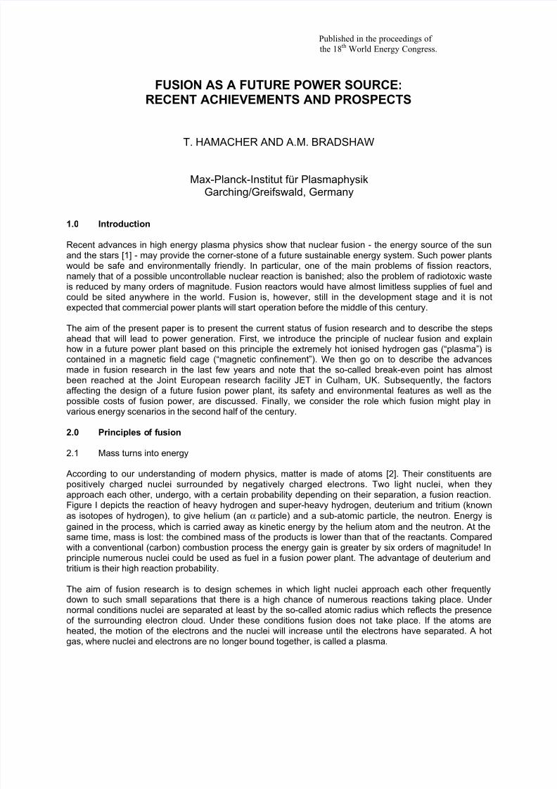
According to our understanding of modern physics, matter is made of atoms [2]. Their constituents arepositively charged nuclei surrounded by negatively charged electrons. Two light nuclei, when theyapproach each other, undergo, with a certain probability depending on their separation, a fusion reaction.Figure I depicts the reaction of heavy hydrogen and super-heavy hydrogen, deuterium and tritium (knownas isotopes of hydrogen), to give helium (an α particle) and a sub-atomic particle, the neutron. Energy isgained in the process, which is carried away as kinetic energy by the helium atom and the neutron. At thesame time, mass is lost: the combined mass of the products is lower than that of the reactants. Comparedwith a conventional (carbon) combustion process the energy gain is greater by six orders of magnitude! Inprinciple numerous nuclei could be used as fuel in a fusion power plant. The advantage of deuterium andtritium is their high reaction probability.
The aim of fusion research is to design schemes in which light nuclei approach each other frequentlydown to such small separations that there is a high chance of numerous reactions taking place. Under normal conditions nuclei are separated at least by the so-called atomic radius which reflects the presenceof the surrounding electron cloud. Under these conditions fusion does not take place. If the atoms areheated, the motion of the electrons and the nuclei will increase until the electrons have separated. A hotgas, where nuclei and electrons are no longer bound together, is called a plasma.
8/4/2019 Review of Fusion Enery Till 2000
http://slidepdf.com/reader/full/review-of-fusion-enery-till-2000 2/19
2
Deuterium Neutron(14 MeV)
Tritium Helium(3,5 MeV)
Figure I: Schematic of the fusion reaction in which deuterium and tritium form a helium atom and aneutron. Mass is lost in the reaction and energy gained.
Even in a plasma, however, the nuclei do not come close enough to react because of mutually repulsiveforces. By heating the plasma to an even higher temperature – one speaks of a very hot plasma - the ionsacquire an even higher velocity, or kinetic energy, and can then overcome the repulsive force. As ananalogy, we can think of a fast ball rolling up a hill against the gravitational force. Clearly, the number of fusion reactions that take place will depend on the plasma temperature and plasma density.
The production of the plasma and its subsequent heating require of course energy. A successful fusionpower plant requires that the power produced by the fusion reaction exceed the power required to produceand heat the plasma. The ratio of the power generated to that consumed (the fusion power amplificationfactor) is called the Q value. Initially, the plasma will be heated by various external sources, e.g.microwaves. With increasing temperature, however, the number of fusion reactions also increases and thefusion reaction itself heats the plasma due to the production of the energetic helium atoms (actually ions,or α particles). The kinetic energy of the helium nuclei exceeds the average kinetic energy of the nuclei of the fuel (deuterium and tritium) by orders of magnitudes. The energy is distributed to the fuel nuclei viacollisions, as in a game of billiards. In fact, a point can be reached - termed ignition - when externalheating is no longer necessary and the value of Q goes to infinity. In practice, however, power plantoperation would probably correspond to a Q value of 20-40.
The state of a very hot plasma and its nearness to the ignition condition can be characterised by theproduct of temperature, density and the so-called energy confinement time. The latter value describes theability of the plasma to maintain its high temperature; in other words, it is a measure for the degree of insulation of the plasma. Ignition can only be achieved if this “fusion triple product” exceeds a certainvalue.
2.2 Magnetic confinement fusion
The temperatures necessary to ignite a plasma are between 100-200 Mio °C. Obviously no solid materialis able to confine a medium with such a high temperature. This dilemma is solved by the fact that in theplasma, all the particles carry an electrical charge and can thus be confined by a magnetic field. (Thecharged particles gyrate around the magnetic field lines.) It transpires that a doughnut-shaped
configuration of the magnetic field “cage” is appropriate for this purpose, although the story is actually alittle more complicated: the magnetic field lines not only have to be doughnut-shaped, they also need tohave a helical twist. This scheme is referred to as magnetic confinement.
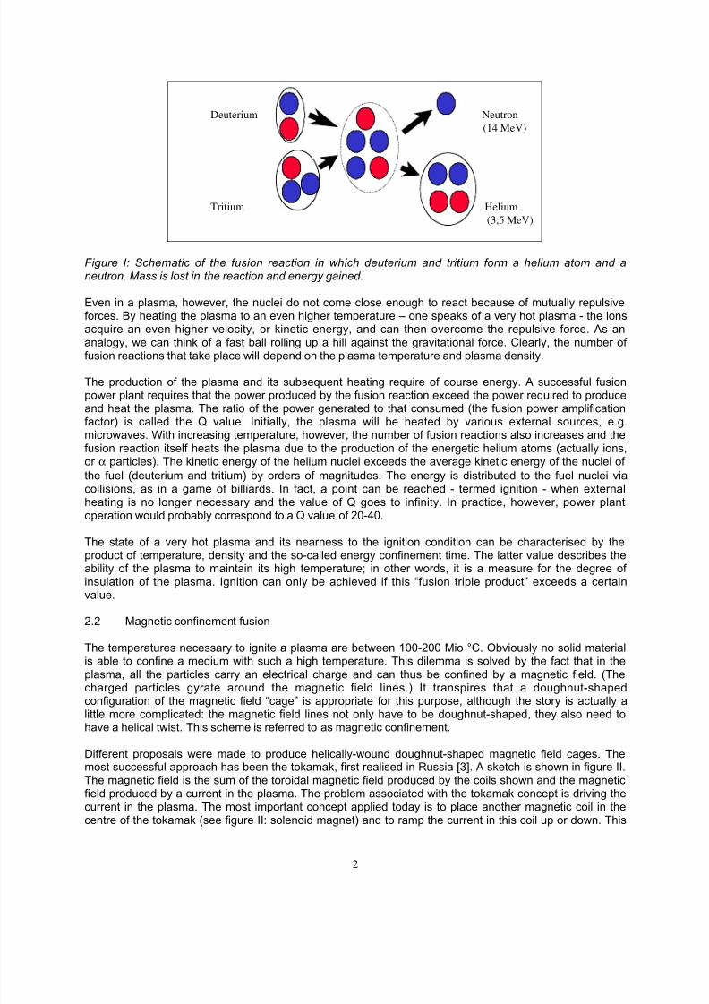
Different proposals were made to produce helically-wound doughnut-shaped magnetic field cages. Themost successful approach has been the tokamak, first realised in Russia [3]. A sketch is shown in figure II.The magnetic field is the sum of the toroidal magnetic field produced by the coils shown and the magneticfield produced by a current in the plasma. The problem associated with the tokamak concept is driving thecurrent in the plasma. The most important concept applied today is to place another magnetic coil in thecentre of the tokamak (see figure II: solenoid magnet) and to ramp the current in this coil up or down. This
8/4/2019 Review of Fusion Enery Till 2000
http://slidepdf.com/reader/full/review-of-fusion-enery-till-2000 3/19
3
will produce a varying magnetic field in the coil which in turn induces a voltage in the plasma (the principleof induction). This voltage can only be sustained for a limited time - one or two hours at the very most.
Figure II: The tokamak has so far been the most successful magnetic confinement scheme. The magnetic field cage - necessary to confine the charged particles - is produced by the superposition of a toroidal magnetic field and a poloidal magnetic field produced by a current in the plasma.
Base load electricity plants need of course to produce power under steady state conditions. Many currentR&D activities are directed towards finding alternative ways of driving the current in the plasma (viamicrowave heating or particle beam injection) or to concentrate on the stellarator, successfully pursued inseveral countries, in particular Germany and Japan, in which no current is necessary.
2.3 Alternative path to fusion
Two alternatives to magnetic confinement are discussed briefly here: inertial confinement and muonicfusion.
In inertial confinement fusion a small pellet of deuterium and tritium fuel is compressed by so-calledmomentum conservation to extremely high density and temperature. (Densities of twenty times the densityof lead and temperatures of 100 Mio ° C are envisaged.) The fuel pellet is encapsulated by an layer of
another material and subject to extremely intense beams of laser radiation or high energy chargedparticles. The outer layer heats up and evaporates. The evaporation products move outwards, but the restof the pellet is compressed inwards, due to momentum conservation. Inertial confinement is mainlyinvestigated in the US and France and to a lesser extent in Japan, Britain and other European countries.Since such experiments can also be used to study the physics of nuclear weapon explosions, much of thisresearch in the US is financed from the defence budget [4]. Inertial fusion is considerably less developedthan magnetic confinement fusion with respect to the realisation of a power plant.
Muonic fusion, which seemed very promising in the beginning, is now only investigated in a fewlaboratories. The idea is to produce muons, which are the heavy sisters of the electron. The muon isinjected into a deuterium-tritium gas mixture. There is a finite probability that the muon will be captured by
8/4/2019 Review of Fusion Enery Till 2000
http://slidepdf.com/reader/full/review-of-fusion-enery-till-2000 4/19
4
a tritium or deuterium atom and form a deuterium-tritium molecule. Since the muon is very heavy, thedimensions of such a molecule are much smaller than those of a normal molecule with bound electrons.Therefore the nuclei will be much closer to each other and there is a greater likelihood that they willundergo a fusion reaction. The problem of this scheme is that the production of muons costs too muchenergy and that the muon will only “catalyse” about two hundred fusion reactions [5].
2.4 The possible design of a fusion power plant
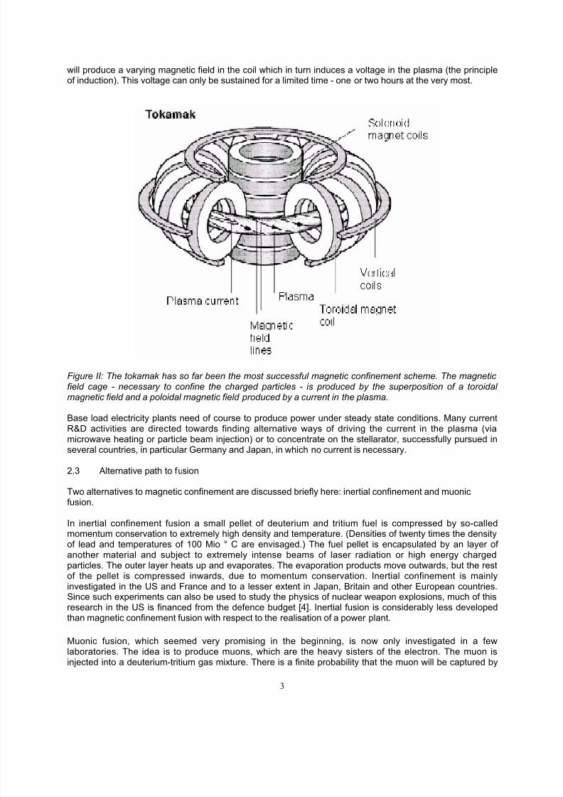
The various features such as steam generator, turbine and current generator will be the same as inconventional nuclear or fossil-fuelled power plants. A flow chart of the energy and material flows in afusion plant are depicted in figure III. The fuel - deuterium and tritium - is injected into the plasma in theform of a frozen pellet so that it will penetrate deeply into the centre. The neutrons leave the plasma andare stopped in the so-called blankets which are modules surrounding the plasma. The neutrons deposit alltheir kinetic energy as heat in the blanket. The blankets also contain lithium in order to breed freshsupplies of tritium via a nuclear reaction (see 4.2). The "ash" of the fusion reaction – helium – is removedvia the divertor. This is the section of the containing vessel where the particles leaving the plasma hit theouter wall. The outer magnetic field lines of the tokamak are especially shaped so that they intersect thewall at special places, namely the divertor plates. Only a small fraction of the fuel is "burnt" so thatdeuterium and tritium are also found in the “exhaust” and can be re-cycled. The tritium produced in theblankets is extracted with a flushing gas - most likely helium - and delivered to the fuel cycle.
Heating
FuelInjection
Plasma
Divertor
Pump
IsotopeSeparationPlant
Blanket
SteamGenerator
Turbine
Generator
Magnets Cryo-System
Figure III: Flow chart for a future fusion reactor: fuel (brown), electrical power (yellow), heat (red), neutron(grey), mechanical power (black) and cooled helium (blue).
The heat produced in the blanket and the divertor is transported via water or helium to the steamgenerator and used to produce electricity to feed to the grid. A small fraction is used to supply electricity tothe various components in the plant itself. Electrical power is required mainly for the cryo-system whichproduces low temperature helium for the super-conducting magnets, the current in the magnets, thecurrent drive and the plasma heating systems.
The reactor core is arranged in different layers like an onion. The inner region is the plasma, surroundedby first wall and blanket. All this is contained in the vacuum vessel. Outside the vacuum vessel are thecoils for the magnetic field. Since the magnets operate at very low temperatures (superconductors), thewhole core is inside a cryostat (see figure VII).
8/4/2019 Review of Fusion Enery Till 2000
http://slidepdf.com/reader/full/review-of-fusion-enery-till-2000 5/19
5
3.0 Status of Fusion Research
3.1 Plasma physics: “break-even” at JET
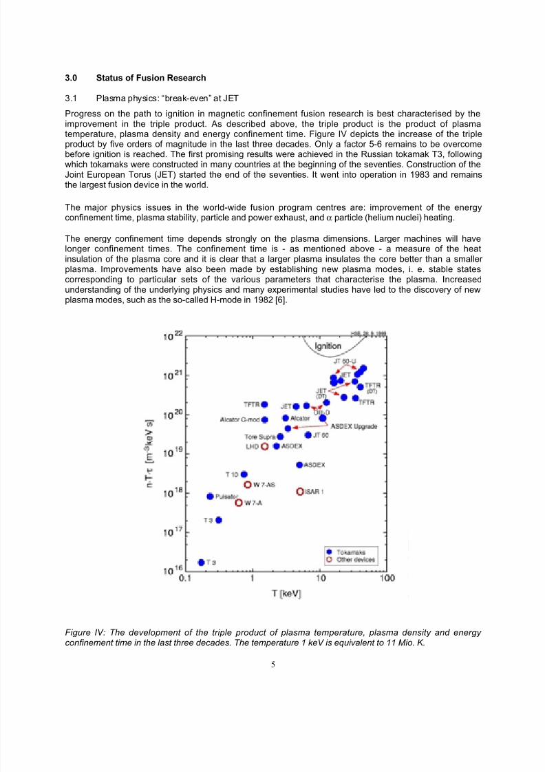
Progress on the path to ignition in magnetic confinement fusion research is best characterised by theimprovement in the triple product. As described above, the triple product is the product of plasma
temperature, plasma density and energy confinement time. Figure IV depicts the increase of the tripleproduct by five orders of magnitude in the last three decades. Only a factor 5-6 remains to be overcomebefore ignition is reached. The first promising results were achieved in the Russian tokamak T3, followingwhich tokamaks were constructed in many countries at the beginning of the seventies. Construction of theJoint European Torus (JET) started the end of the seventies. It went into operation in 1983 and remainsthe largest fusion device in the world.
The major physics issues in the world-wide fusion program centres are: improvement of the energyconfinement time, plasma stability, particle and power exhaust, and α particle (helium nuclei) heating.
The energy confinement time depends strongly on the plasma dimensions. Larger machines will havelonger confinement times. The confinement time is - as mentioned above - a measure of the heatinsulation of the plasma core and it is clear that a larger plasma insulates the core better than a smaller
plasma. Improvements have also been made by establishing new plasma modes, i. e. stable statescorresponding to particular sets of the various parameters that characterise the plasma. Increasedunderstanding of the underlying physics and many experimental studies have led to the discovery of newplasma modes, such as the so-called H-mode in 1982 [6].
Figure IV: The development of the triple product of plasma temperature, plasma density and energy confinement time in the last three decades. The temperature 1 keV is equivalent to 11 Mio. K.
8/4/2019 Review of Fusion Enery Till 2000
http://slidepdf.com/reader/full/review-of-fusion-enery-till-2000 6/19
6
Establishing the H-mode improves the energy confinement time by a factor of two. Attention now turnsincreasingly towards advanced plasma scenarios which are characterised by an internal transport barrier [7]. Plasma stability is a matter of particular importance for the economics of fusion. The figure of merit isthe ratio of the plasma pressure to the pressure of the magnetic field. This ratio is very small in currentmachines. If this value is exceeded, the plasma becomes unstable and collapses in a so-called disruption.Limits also exist for the plasma density, although these are generally soft and considerable improvementsmay be expected in future. Major improvements are expected from active measures to shape the plasmaby special control mechanisms [8].
The particle and power exhaust seemed to a major problem for several years. As mentioned above, aviable solution for the power exhaust is the divertor concept [9]: with the help of additional magnets thestream of plasma particles leaving the core is directed to the divertor plates. These plates are made fromspecial material, either carbon fibre composites (CFC) or tungsten. Special cooling schemes have beendesigned for the plates which have to withstand heat loads of the order of 10 MW/m 2.
Experimentally it has also been demonstrated that the residence time of helium in the plasma poses nosevere problem [10] and the helium "ash" can be transported efficiently to the divertor to be removed fromthe system.
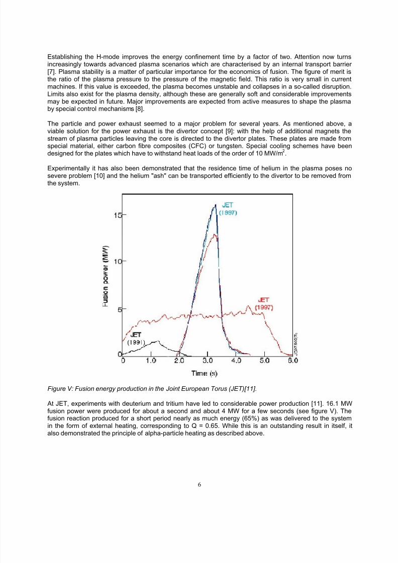
Figure V: Fusion energy production in the Joint European Torus (JET)[11].
At JET, experiments with deuterium and tritium have led to considerable power production [11]. 16.1 MWfusion power were produced for about a second and about 4 MW for a few seconds (see figure V). Thefusion reaction produced for a short period nearly as much energy (65%) as was delivered to the systemin the form of external heating, corresponding to Q = 0.65. While this is an outstanding result in itself, italso demonstrated the principle of alpha-particle heating as described above.
8/4/2019 Review of Fusion Enery Till 2000
http://slidepdf.com/reader/full/review-of-fusion-enery-till-2000 7/19
7
3.2 Development of fusion technology
Fusion gives rise to complex technologies and still demands progress in various fields such assuperconducting magnets, high heat load materials, materials able to withstand high neutron flux, remotehandling devices and plasma heating techniques.
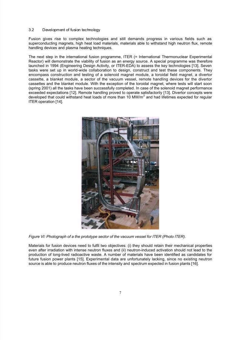
The next step in the international fusion programme, ITER (= International Thermonuclear ExperimentalReactor) will demonstrate the viability of fusion as an energy source. A special programme was thereforelaunched in 1994 (Engineering Design Activity, or ITER-EDA) to assess the key technologies [13]. Seventasks were set up in world-wide collaboration to design, construct and test these components. Theyencompass construction and testing of a solenoid magnet module, a toroidal field magnet, a divertor cassette, a blanket module, a sector of the vacuum vessel, remote handling devices for the divertor cassettes and the blanket module. With the exception of the toroidal magnet, where tests will start soon(spring 2001) all the tasks have been successfully completed. In case of the solenoid magnet performanceexceeded expectations [12]. Remote handling proved to operate satisfactorily [13]. Divertor concepts weredeveloped that could withstand heat loads of more than 10 MW/m 2 and had lifetimes expected for regular ITER operation [14].
Figure VI: Photograph of a the prototype sector of the vacuum vessel for ITER (Photo ITER).Materials for fusion devices need to fulfil two objectives: (i) they should retain their mechanical propertieseven after irradiation with intense neutron fluxes and (ii) neutron-induced activation should not lead to theproduction of long-lived radioactive waste. A number of materials have been identified as candidates for future fusion power plants [15]. Experimental data are unfortunately lacking, since no existing neutronsource is able to produce neutron fluxes of the intensity and spectrum expected in fusion plants [16].
8/4/2019 Review of Fusion Enery Till 2000
http://slidepdf.com/reader/full/review-of-fusion-enery-till-2000 8/19
8
4.0 Path to a Fusion Power Plant
The European fusion strategy has always been reactor-oriented. Via two major steps (ITER andsubsequently the demonstration reactor DEMO) the programme is intended to provide the scientific andtechnological basis to build and operate economically viable fusion power plants by the middle of the 21 st
century. The first step has three major parts: construction and operation of ITER, development of fusiontechnologies including advanced materials and improvement of the magnetic confinement scheme.
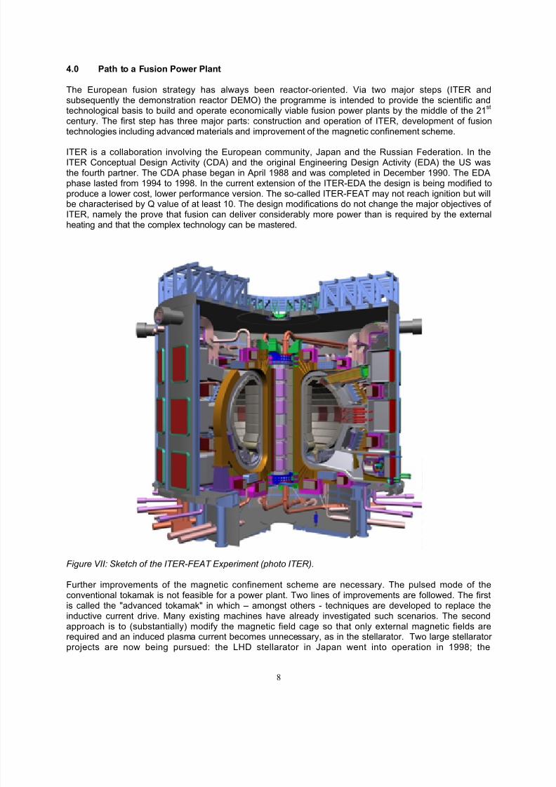
ITER is a collaboration involving the European community, Japan and the Russian Federation. In theITER Conceptual Design Activity (CDA) and the original Engineering Design Activity (EDA) the US wasthe fourth partner. The CDA phase began in April 1988 and was completed in December 1990. The EDAphase lasted from 1994 to 1998. In the current extension of the ITER-EDA the design is being modified toproduce a lower cost, lower performance version. The so-called ITER-FEAT may not reach ignition but willbe characterised by Q value of at least 10. The design modifications do not change the major objectives of ITER, namely the prove that fusion can deliver considerably more power than is required by the externalheating and that the complex technology can be mastered.
Figure VII: Sketch of the ITER-FEAT Experiment (photo ITER).
Further improvements of the magnetic confinement scheme are necessary. The pulsed mode of theconventional tokamak is not feasible for a power plant. Two lines of improvements are followed. The firstis called the "advanced tokamak" in which – amongst others - techniques are developed to replace theinductive current drive. Many existing machines have already investigated such scenarios. The secondapproach is to (substantially) modify the magnetic field cage so that only external magnetic fields arerequired and an induced plasma current becomes unnecessary, as in the stellarator. Two large stellarator projects are now being pursued: the LHD stellarator in Japan went into operation in 1998; the
8/4/2019 Review of Fusion Enery Till 2000
http://slidepdf.com/reader/full/review-of-fusion-enery-till-2000 9/19
9
WENDELSTEIN 7-X stellarator in Germany is expected to start operation in 2006. A smaller stellarator isin operation in Spain.
The development of fusion materials requires the construction of an intense neutron source. A world-widecollaboration under the auspices of the International Energy Agency (IEA) in Paris has been launched todesign the International Fusion Material Irradiation Facility (IFMIF). The conceptual design report wasproduced at the end of 1996.
All these activities, i.e. ITER, advanced concepts and technological development will form the basis for DEMO, the detailed design of which can be started after ITER has operated for about five years.
5.0 Characterisation of fusion as power source
5.1 Fusion plant models
A number of detailed system studies have been performed in the last thirty years in order to study thepossible design of future fusion plants [17]. On the basis of these studies it is possible to analyseeconomic and environmental impact. The detailed design work on ITER adds useful complementarymaterial.
5.2 Fuel and material availability, energy requirements
One of the main motivations from the very beginning of fusion research has been that fusion can beconsidered as a practically unlimited source of energy. The argument is based on the abundance of thefusion fuels - lithium and deuterium - and the very small quantities required [18]. A 1 GWe fusion power plant would require annually 110 kg deuterium and 380 kg lithium consumption.
Deuterium is a hydrogen isotope. In terrestrial hydrogen sources, such as sea water, deuterium makes upone part in 6700. Given the above annual consumption rates it can be shown that fusion could continue tosupply energy for many millions of years. The oceans have a total mass of 1.4 * 10 21 kg and thereforecontain 4.6 * 10 16 kg of deuterium; moreover, there is already a mature technology for extracting thedeuterium. One of the main applications is the production of heavy water for heavy water-moderatedfission reactors. Existing plants can produce up to 250 t/a of heavy water which means a production of 50t/a of deuterium. This would be enough to supply deuterium for 500 fusion plants each with 1 GWecapacity. Obviously deuterium supply places no burden on the extensive use of fusion. What abouttritium? As we have mentioned above, tritium, also a hydrogen isotope, will be bred from lithium using thehigh flux of fusion neutrons. Lithium is found in nature in two different isotopes 6Li (7.4 %) and 7Li (92.6%). The two nuclear reactions
6Li + n -> T + 4He + 4.8 MeV
7Li + n -> T + 4He + n - 2.5 MeV
are relevant Since the second reaction is endothermic only neutrons with an energy higher than thethreshold can initiate this process. In most blanket concepts the reaction with 6Li dominates, but in order toreach a breeding ratio exceeding unity the 7Li content might be essential.
Lithium can be found in:
- salt brines, in concentrations ranging from 0.015 % to 0.2 %- minerals: spodumene, petalite, eucrypotite, amblygonite, lepidolite.; the concentration
varies between 0.6 % and 2.1 %.- sea water; the concentration in sea water is 0.173 mg/l (Li +).
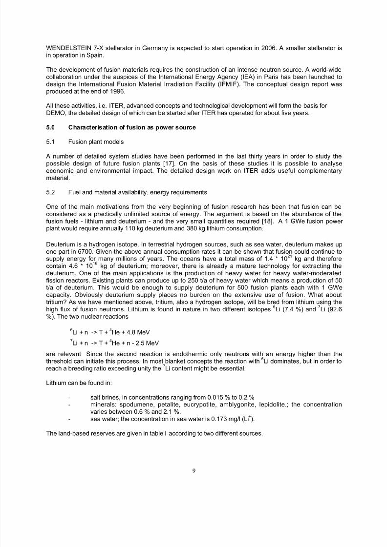
The land-based reserves are given in table I according to two different sources.
8/4/2019 Review of Fusion Enery Till 2000
http://slidepdf.com/reader/full/review-of-fusion-enery-till-2000 10/19
10
Table I: Land reserves of Lithium.
Material Current Production Reserve [19] Reserve base [19] Reserve [20]Lithium 15,000 t 3,400,000 t 9,400,000 t 1,106,000 t
While the annual consumption of lithium in a fusion plant is low, the lithium inventories in the blankets are
much larger [21, 23]. At least a couple of hundred tons of lithium are necessary to build a blanket. It isexpected that most of the lithium can be recovered and re-used, although radioactive impurities such astritium will complicate the handling. No detailed concept for recovering lithium has been developed so far.The lithium supply is, however, a minor problem in the context of the construction of the whole plant:lithium can be purchased today for around 17 Euro/kg and the blanket containing 146 t of lithium needs tobe replaced five times in the life of a fusion plant, which would amount to only 12 MEuro. Beside the land-based resources there is a total amount of 2.24 * 10 11 t lithium in sea water. Techniques to extract lithiumfrom sea water have already been investigated [25]. The associated energy consumption has also beeninvestigated [26]. The ultimate lithium resources in sea water are thus practically unlimited.
0.0001
0.001
0.01
0.1
1
10
100
1000
Be V Cr Mn Ni Cu Nb Mo Sn Ta W Pb
R a t i o o f s p e c i f i c m a t e r i a l
r e q u i r e m e n t s
t o c u r r e n t r e s e r v e s
Model 1Model 1 AModel 1 BModel 2
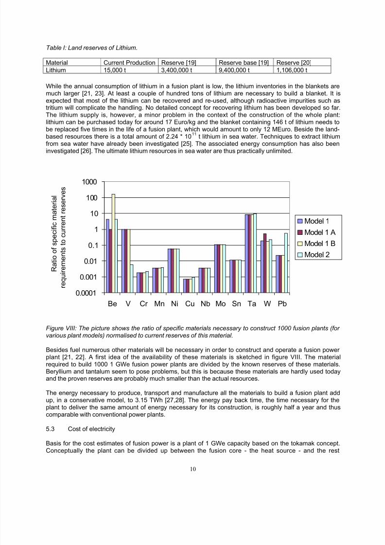
Figure VIII: The picture shows the ratio of specific materials necessary to construct 1000 fusion plants (for various plant models) normalised to current reserves of this material.
Besides fuel numerous other materials will be necessary in order to construct and operate a fusion power plant [21, 22]. A first idea of the availability of these materials is sketched in figure VIII. The materialrequired to build 1000 1 GWe fusion power plants are divided by the known reserves of these materials.Beryllium and tantalum seem to pose problems, but this is because these materials are hardly used todayand the proven reserves are probably much smaller than the actual resources.
The energy necessary to produce, transport and manufacture all the materials to build a fusion plant addup, in a conservative model, to 3.15 TWh [27,28]. The energy pay back time, the time necessary for theplant to deliver the same amount of energy necessary for its construction, is roughly half a year and thuscomparable with conventional power plants.
5.3 Cost of electricity
Basis for the cost estimates of fusion power is a plant of 1 GWe capacity based on the tokamak concept.Conceptually the plant can be divided up between the fusion core - the heat source - and the rest
8/4/2019 Review of Fusion Enery Till 2000
http://slidepdf.com/reader/full/review-of-fusion-enery-till-2000 11/19
11
consisting of turbines, generators, switchboards. The assumptions in the underlying physics andtechnology seem well with reach based on current achievements. If progress in fusion technology isfaster, it might of course lead to considerably lower costs.
Most of the components of the fusion power core are unique for fusion. The basis for the cost estimates of these components is (i) existing experience with operating fusion experiments, (ii) the experience withdesigning ITER [30] and (iii) numerous system studies. The ITER experience is of particular importancebecause it combines system studies and real manufacturing experience. As mentioned earlier, part of theITER activities to date have been the design, construction and testing of central components of theexperiment. The following discussion is based on [29,31,32].
Magnets make up 30 % of the investment costs of the fusion core for a prototype and another big item arethe buildings. The rest splits up into numerous items. Blanket and divertor make up 14 % and 3 %,respectively, although these items will have to be replaced regularly. The divertor will be replaced everysecond year, the blanket every fifth year. Two possible technological developments should be mentionedwhich might lead in the long run to cost reductions. The pressure of the magnetic field has to balance thepressure of the plasma. For specific physical reasons, however, the magnetic pressure needs to muchhigher than the plasma pressure in current installations. Progress in plasma physics could reduce thisratio in future and thus reduce the size and cost of the magnets. Also alower replacement frequency of blanket and divertor due to the development of advanced materials mightlead to a further reduction.
Cost of electricity (COE) is the sum of the capital costs for the fusion core (39 %) and the rest of the plant(23 %), the costs for the replacement of divertor and blanket during operation (30 %), fuel, operation,maintenance and decommissioning (8 %). An annual load factor of 75 %, an operating lifetime of 30 yearsand an real interest rate (corrected for inflation) of 5 % are also assumed. The investment costs for DEMOare expected to be roughly 10000 Euro/kW (1995) [29] giving an expected COE of 165 mEuro/kWh.
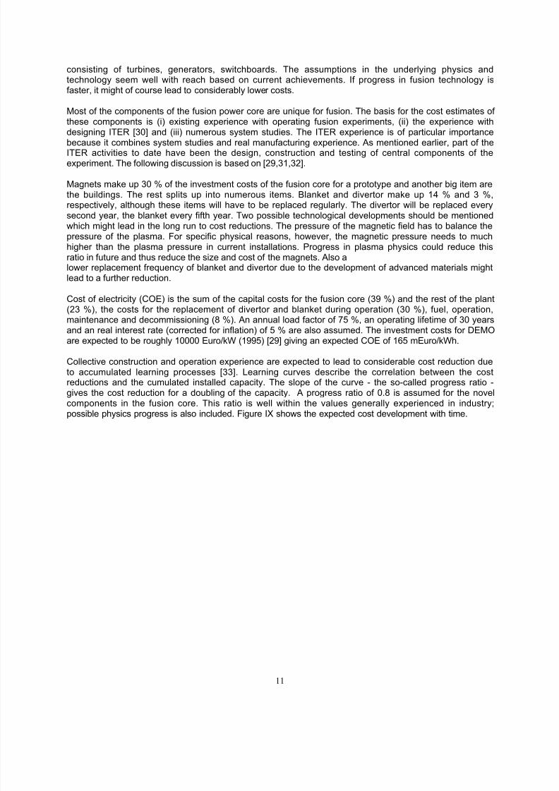
Collective construction and operation experience are expected to lead to considerable cost reduction dueto accumulated learning processes [33]. Learning curves describe the correlation between the costreductions and the cumulated installed capacity. The slope of the curve - the so-called progress ratio -gives the cost reduction for a doubling of the capacity. A progress ratio of 0.8 is assumed for the novelcomponents in the fusion core. This ratio is well within the values generally experienced in industry;
possible physics progress is also included. Figure IX shows the expected cost development with time.
8/4/2019 Review of Fusion Enery Till 2000
http://slidepdf.com/reader/full/review-of-fusion-enery-till-2000 12/19
12
0
2000
4000
6000
8000
10000
12000
2000 2010 2020 2030 2040 2050 2060 2070 2080
Year
C o s t [ M
E u r o ]
0
5
10
15
20
25
30
35
I n s t a l l e d C a p a c i t y
[ G W
]
Fusion Core
Balance of Plant
Total
CumulatedCapacity
Figure IX: Learning curves for fusion power plants [29].
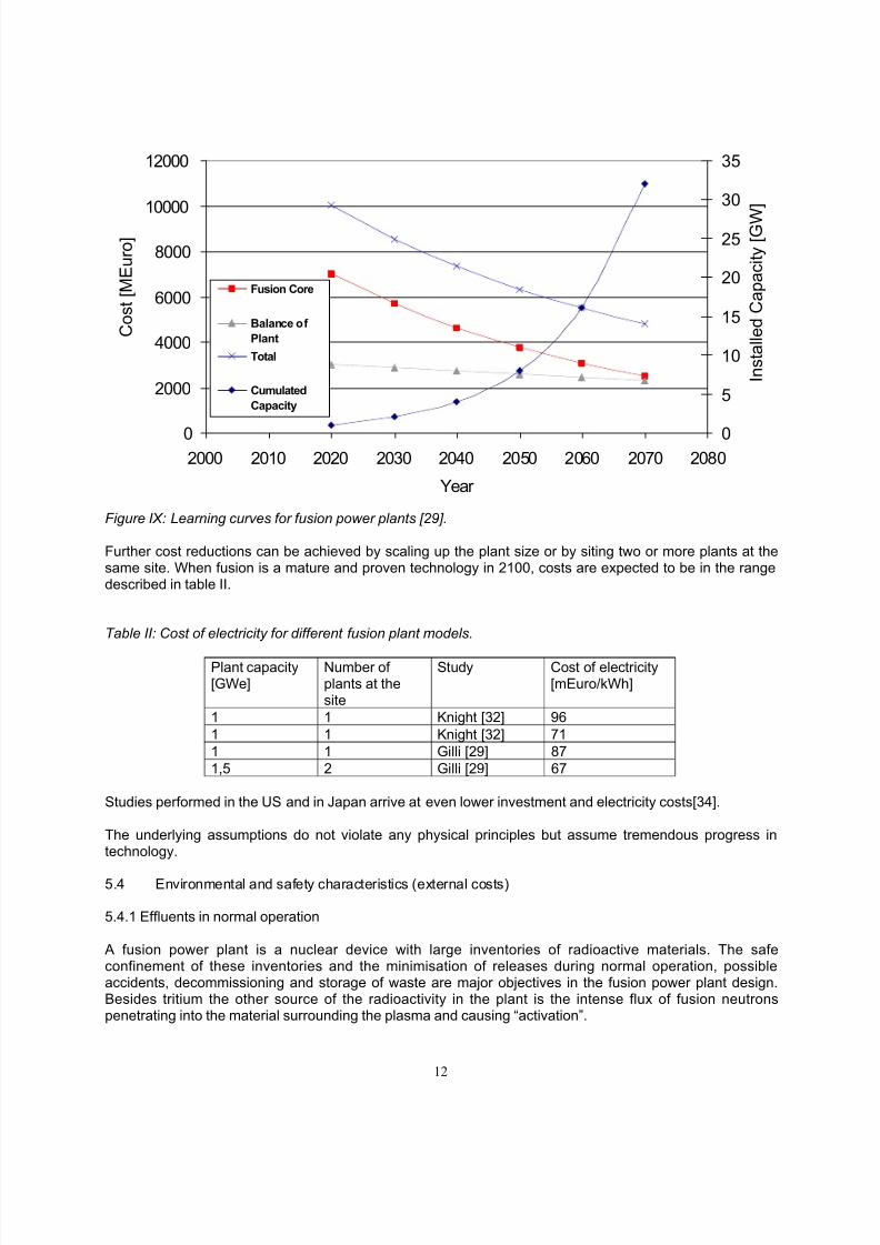
Further cost reductions can be achieved by scaling up the plant size or by siting two or more plants at thesame site. When fusion is a mature and proven technology in 2100, costs are expected to be in the rangedescribed in table II.
Table II: Cost of electricity for different fusion plant models.
Plant capacity[GWe]
Number of plants at thesite
Study Cost of electricity[mEuro/kWh]
1 1 Knight [32] 961 1 Knight [32] 711 1 Gilli [29] 871,5 2 Gilli [29] 67
Studies performed in the US and in Japan arrive at even lower investment and electricity costs[34].
The underlying assumptions do not violate any physical principles but assume tremendous progress intechnology.
5.4 Environmental and safety characteristics (external costs)
5.4.1 Effluents in normal operation
A fusion power plant is a nuclear device with large inventories of radioactive materials. The safeconfinement of these inventories and the minimisation of releases during normal operation, possibleaccidents, decommissioning and storage of waste are major objectives in the fusion power plant design.Besides tritium the other source of the radioactivity in the plant is the intense flux of fusion neutronspenetrating into the material surrounding the plasma and causing “activation”.
8/4/2019 Review of Fusion Enery Till 2000
http://slidepdf.com/reader/full/review-of-fusion-enery-till-2000 13/19
13
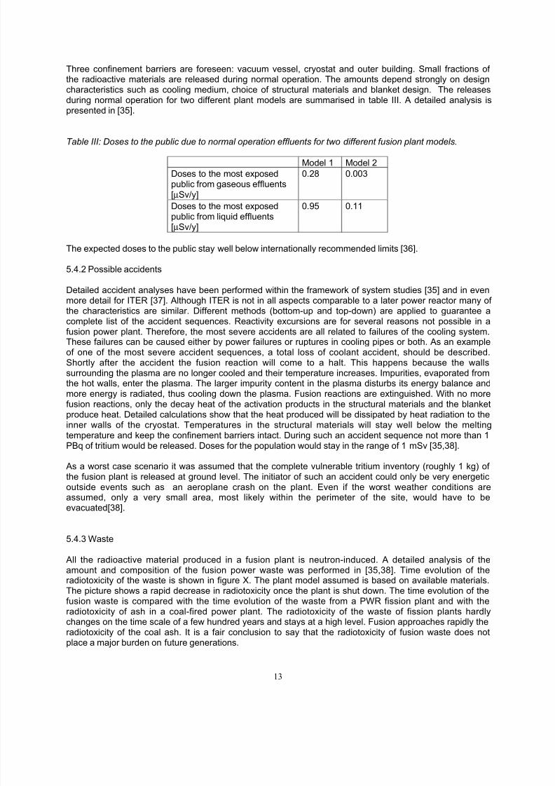
Three confinement barriers are foreseen: vacuum vessel, cryostat and outer building. Small fractions of the radioactive materials are released during normal operation. The amounts depend strongly on designcharacteristics such as cooling medium, choice of structural materials and blanket design. The releasesduring normal operation for two different plant models are summarised in table III. A detailed analysis ispresented in [35].
Table III: Doses to the public due to normal operation effluents for two different fusion plant models.
Model 1 Model 2Doses to the most exposedpublic from gaseous effluents[µSv/y]
0.28 0.003
Doses to the most exposedpublic from liquid effluents[µSv/y]
0.95 0.11
The expected doses to the public stay well below internationally recommended limits [36].
5.4.2 Possible accidents
Detailed accident analyses have been performed within the framework of system studies [35] and in evenmore detail for ITER [37]. Although ITER is not in all aspects comparable to a later power reactor many of the characteristics are similar. Different methods (bottom-up and top-down) are applied to guarantee acomplete list of the accident sequences. Reactivity excursions are for several reasons not possible in afusion power plant. Therefore, the most severe accidents are all related to failures of the cooling system.These failures can be caused either by power failures or ruptures in cooling pipes or both. As an exampleof one of the most severe accident sequences, a total loss of coolant accident, should be described.Shortly after the accident the fusion reaction will come to a halt. This happens because the wallssurrounding the plasma are no longer cooled and their temperature increases. Impurities, evaporated fromthe hot walls, enter the plasma. The larger impurity content in the plasma disturbs its energy balance andmore energy is radiated, thus cooling down the plasma. Fusion reactions are extinguished. With no morefusion reactions, only the decay heat of the activation products in the structural materials and the blanketproduce heat. Detailed calculations show that the heat produced will be dissipated by heat radiation to theinner walls of the cryostat. Temperatures in the structural materials will stay well below the meltingtemperature and keep the confinement barriers intact. During such an accident sequence not more than 1PBq of tritium would be released. Doses for the population would stay in the range of 1 mSv [35,38].
As a worst case scenario it was assumed that the complete vulnerable tritium inventory (roughly 1 kg) of the fusion plant is released at ground level. The initiator of such an accident could only be very energeticoutside events such as an aeroplane crash on the plant. Even if the worst weather conditions areassumed, only a very small area, most likely within the perimeter of the site, would have to beevacuated[38].
5.4.3 Waste
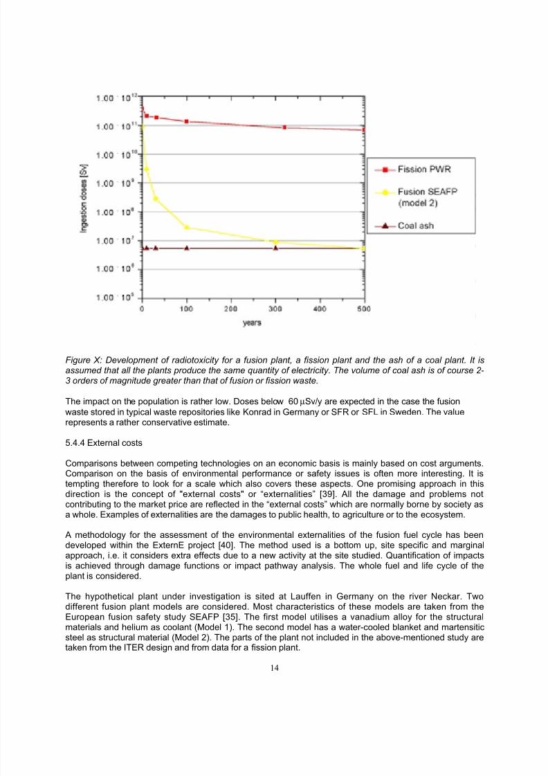
All the radioactive material produced in a fusion plant is neutron-induced. A detailed analysis of theamount and composition of the fusion power waste was performed in [35,38]. Time evolution of theradiotoxicity of the waste is shown in figure X. The plant model assumed is based on available materials.The picture shows a rapid decrease in radiotoxicity once the plant is shut down. The time evolution of thefusion waste is compared with the time evolution of the waste from a PWR fission plant and with theradiotoxicity of ash in a coal-fired power plant. The radiotoxicity of the waste of fission plants hardlychanges on the time scale of a few hundred years and stays at a high level. Fusion approaches rapidly theradiotoxicity of the coal ash. It is a fair conclusion to say that the radiotoxicity of fusion waste does notplace a major burden on future generations.
8/4/2019 Review of Fusion Enery Till 2000
http://slidepdf.com/reader/full/review-of-fusion-enery-till-2000 14/19
14
Figure X: Development of radiotoxicity for a fusion plant, a fission plant and the ash of a coal plant. It isassumed that all the plants produce the same quantity of electricity. The volume of coal ash is of course 2-3 orders of magnitude greater than that of fusion or fission waste.
The impact on the population is rather low. Doses below 60 µSv/y are expected in the case the fusionwaste stored in typical waste repositories like Konrad in Germany or SFR or SFL in Sweden. The valuerepresents a rather conservative estimate.
5.4.4 External costs
Comparisons between competing technologies on an economic basis is mainly based on cost arguments.Comparison on the basis of environmental performance or safety issues is often more interesting. It istempting therefore to look for a scale which also covers these aspects. One promising approach in thisdirection is the concept of "external costs" or “externalities” [39]. All the damage and problems notcontributing to the market price are reflected in the “external costs” which are normally borne by society asa whole. Examples of externalities are the damages to public health, to agriculture or to the ecosystem.
A methodology for the assessment of the environmental externalities of the fusion fuel cycle has beendeveloped within the ExternE project [40]. The method used is a bottom up, site specific and marginalapproach, i.e. it considers extra effects due to a new activity at the site studied. Quantification of impactsis achieved through damage functions or impact pathway analysis. The whole fuel and life cycle of theplant is considered.
The hypothetical plant under investigation is sited at Lauffen in Germany on the river Neckar. Twodifferent fusion plant models are considered. Most characteristics of these models are taken from theEuropean fusion safety study SEAFP [35]. The first model utilises a vanadium alloy for the structuralmaterials and helium as coolant (Model 1). The second model has a water-cooled blanket and martensiticsteel as structural material (Model 2). The parts of the plant not included in the above-mentioned study aretaken from the ITER design and from data for a fission plant.
8/4/2019 Review of Fusion Enery Till 2000
http://slidepdf.com/reader/full/review-of-fusion-enery-till-2000 15/19
15
0
0.5
1
1.5
2
M a t e r i a l
m a n u f a c t u r i n g
C o n s t r u c t i o n
O p e r a t i o n
D e c o m m
i s s i o n i n g
W
a s t e d i s p o s a l
S i t e r e s t o r a t i o n
E x t e r n a l
C o s t s
[ m E u r o / k
W h ]
Model 1
Model 2
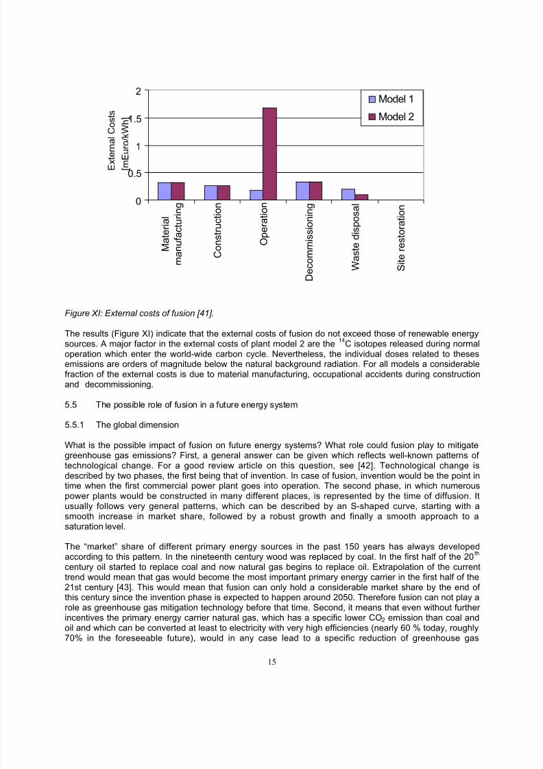
Figure XI: External costs of fusion [41].
The results (Figure XI) indicate that the external costs of fusion do not exceed those of renewable energysources. A major factor in the external costs of plant model 2 are the 14C isotopes released during normaloperation which enter the world-wide carbon cycle. Nevertheless, the individual doses related to thesesemissions are orders of magnitude below the natural background radiation. For all models a considerablefraction of the external costs is due to material manufacturing, occupational accidents during constructionand decommissioning.
5.5 The possible role of fusion in a future energy system
5.5.1 The global dimension
What is the possible impact of fusion on future energy systems? What role could fusion play to mitigategreenhouse gas emissions? First, a general answer can be given which reflects well-known patterns of technological change. For a good review article on this question, see [42]. Technological change isdescribed by two phases, the first being that of invention. In case of fusion, invention would be the point intime when the first commercial power plant goes into operation. The second phase, in which numerouspower plants would be constructed in many different places, is represented by the time of diffusion. Itusually follows very general patterns, which can be described by an S-shaped curve, starting with asmooth increase in market share, followed by a robust growth and finally a smooth approach to asaturation level.
The “market” share of different primary energy sources in the past 150 years has always developedaccording to this pattern. In the nineteenth century wood was replaced by coal. In the first half of the 20 th
century oil started to replace coal and now natural gas begins to replace oil. Extrapolation of the currenttrend would mean that gas would become the most important primary energy carrier in the first half of the21st century [43]. This would mean that fusion can only hold a considerable market share by the end of this century since the invention phase is expected to happen around 2050. Therefore fusion can not play arole as greenhouse gas mitigation technology before that time. Second, it means that even without further incentives the primary energy carrier natural gas, which has a specific lower CO 2 emission than coal andoil and which can be converted at least to electricity with very high efficiencies (nearly 60 % today, roughly70% in the foreseeable future), would in any case lead to a specific reduction of greenhouse gas
8/4/2019 Review of Fusion Enery Till 2000
http://slidepdf.com/reader/full/review-of-fusion-enery-till-2000 16/19
16
emissions. In comparison with coal this combined advantage would produce roughly a factor of threelower CO 2 emissions per kiloWatthour delivered. If all coal-fired plants were to be replaced by veryefficient gas-fired plants the electricity demand could triple without increase in emissions. Third, the timewhen the share of natural gas will pass its maximum roughly coincides with the “invention” (thetechnological and economic proof of principle) of fusion.
Another very important point is of course the future development of energy usage and, in particular, theelectricity demand. Scenarios made by the International Institute of Applied System Analysis (IIASA) andthe World Energy Council (WEC) describe various possible paths into the future [44]. Of the scenarioslabelled A, B and C, A is a high growth scenario, B an average growth scenario and C an ecologicallydriven scenario. Even in the C scenario electricity consumption will increase considerably even after 2050,leaving enough space for fusion, even without replacing older technologies. It must be noted that, giventhe long lead-time, alternative low-GHG electricity generating techniques might compete for the samepotential market as fusion. While predicting winners or losers is obviously a very long shot, continued R&Dis an absolute necessity for all of them.
5.5.2 Fusion in Western Europe
In the framework of socio-economic studies on fusion (SERF), which have been conducted by theEuropean Commission and the Fusion Associations, a study was carried out on the possible impact of fusion on the future West-European energy market, on the assumption that fusion is commerciallyavailable in the year 2050. The scenario horizon is based the complete 21 st century. The scenarios wereperformed with the programme package MARKAL [45]. Details of the analysis can be found in [29].
Two different scenarios were explored which differ in the discount rates, level of energy demand,availability of fossil fuels and energy price projections. The first scenario is called Market Drive (MD):interest rates on power generation investments are 8%, interest rates on end-use investments are higher.15 % of the world resources of fossil fuels are available to Western Europe and a rapid increase in the oilprice is expected. The second scenario is called Rational Perspective (RP): discount rates are 5 % acrossthe whole energy sector, but only 10,5 % of the world fossil fuel resources are available to Western-Europe. The oil price increases more slowly. Energy demand is higher in scenario Market Drive. Bothscenarios assume that the capacity of nuclear fission never exceeds the current level. Fission is expectedto phase out at 2100.
Scenario Rationale Perspective
01000
200030004000500060007000
base 550 500 450
Stabilised atmospheric CO2-concentration [ppm]
E l e c t r i c i t y
P r o d u c t i o n
[ T W h ] New Renewables
Hydro
Fusion
FissionNatural Gas
Coal
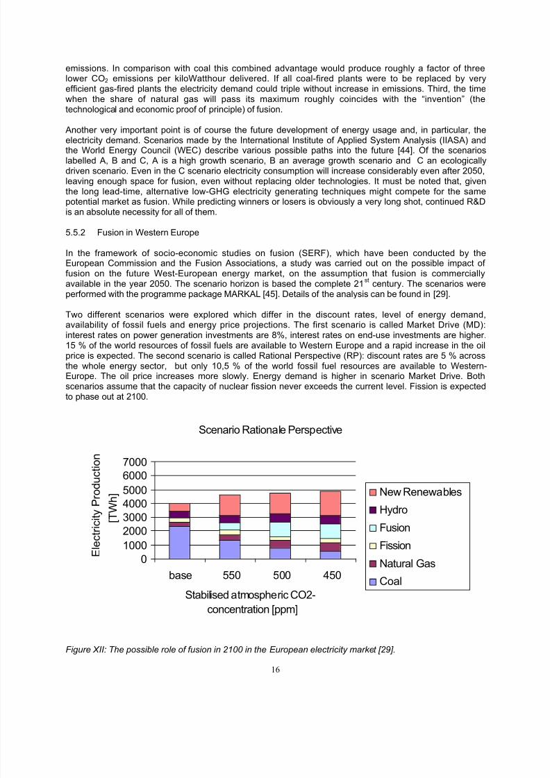
Figure XII: The possible role of fusion in 2100 in the European electricity market [29].
8/4/2019 Review of Fusion Enery Till 2000
http://slidepdf.com/reader/full/review-of-fusion-enery-till-2000 17/19
17
The demand for energy increases in the two scenarios. In Market Drive it more than doubles in relation tothe 1990 value and in Rationale Perspective it increases by more than 50 %. Steady increases inefficiency keep the overall primary energy demand roughly constant over the whole scenario horizon. Thedemand for electrical energy increases in both scenarios roughly by a factor two.
The development of energy supply and conversion technologies, especially further progress in economicperformance and efficiencies, is based upon detailed assessments of the literature and on the studies byFusion Associations, and have been, where appropriate, guided by learning curves. The increase inefficiency or the decrease in costs are time-dependent. A detailed description of the supply technologiescan be found in [46]. Another important point is the future development of fuel prices. An increase in the oilprice to $25/bbl (RP) or 29,5/bbl (MD) in 2100 is expected. The gas price is strongly tied to the oil price.The price for hard coal is considerably flat over the whole period investigated. In both scenarios neither new renewables nor fusion will win considerable market shares until the year 2100. Fossil fuels remain themost important primary energy sources. Two shifts in the use of fossil fuels can be identified. The use of gas increases considerably until the middle of the 21 st century when the easily accessible natural gasreserves are exhausted and its price has substantially increased. Coal will then win again a market shareand advance to the most important primary energy carrier at the end of the 21 st century. The picturechange drastically, however, if future CO 2 emissions are to be restricted in order to reduce the risk of climate changes. These cases are constructed in such a way that the global emissions would lead in thelong term to a stabilisation of the CO 2 concentration in the atmosphere. Different values for thestabilisation concentration are assumed. Western Europe would be allowed to produce 10 % of theseglobal emissions. The time-dependent allowed emissions are constraints in the optimisation. If theseconstraints are applied to the scenarios, the energy mix changes considerable. The share of the electricitysupply technologies in 2100 is shown in figure XII. Fusion and new renewables such as wind and solar win considerable market shares. The conclusion can be summarised as follows: fusion can win shares inthe electricity market if (i) the further use of fission is limited and (ii) if greenhouse gas emissions areconstrained.
Similar studies have been performed in Japan [47] and the US [48].
6.0 Summary
Fusion research has made considerable progress in the last three decades. More than 16 MW fusionpower have been produced in the joint European experiment JET at a Q value (fusion power amplificationfactor) of 0.65.
Technologies for the next step in the international fusion programme (ITER) have already been improvedby intense engineering R&D and the construction and test of prototypes. The ITER experiment still awaitsapproval. Sites in France, Canada and Japan are, however, being discussed. ITER is intended todemonstrate the proof of principle for magnetic confinement fusion as a future energy source.
Detailed investigations on the safety, environmental and socio-economic aspects of fusion have beenperformed. Fusion - if fully developed in 2050 - will fit into a sustainable energy system and be able tosupply electricity for millennia to come at economically acceptable costs.
8/4/2019 Review of Fusion Enery Till 2000
http://slidepdf.com/reader/full/review-of-fusion-enery-till-2000 18/19
18
Literature
[1] Bethe H.A.: "Energy production in stars" Phys. Rev. 55 (1939) 434 an references therein[2] Beiser, A: Perspectives of Modern Physics, McGraw-Hill, 14 th printing 1984[3] Artsimovich L. A..:"Tokamak devices", Nucl. Fus., 12, 2 (1972) 215[4] http://www.llnl.gov/nif/index.html[5] L. W. Alvarez et al., Phys. Rev., 105:1127-1128, 1957.[6] F. Wagner, 1982 Phys. Rev. Lett. 49 1408[7] Gruber O. et al., 1999 Phys. Rev. Lett. 83 1790[8] Zohm H. et al., 1999 Nucl. Fusion 39 577[9] Janetschitz G. et al., 18th IAEA Fusion Energy Conference, to be published[10] Bosch H-S., 1997 Plasma Phys. Control. Fusion 39 1771[11] Keilhacker M. and the JET team 1999 Nucl. Fusion 39 209[12] Tsuji H. 18th IAEA Fusion Energy Conference, to be published[13] Aymar R., 1999 Fusion Eng. Des. 40 115 (remote)[14] Tivey R., 1999 Fusion Eng. Des. 40 207 (divertor)[15] Ehrlich K., Materials Research towards a Fusion Reactor, 21 st Symposium on Fusion
Technology, Madrid, 2000, to be published in Fusion Eng. Des.[16] Cozzani F., 1999 Fusion Eng. Des. 40 414 (IFMIF)[17] Raeder J. et al, Kontrollierte Kernfusion, 1981, Stuttgart[18] S. Glasstone, R. H. Lovberg, Controlled Thermonuclear Reactions, 1 st edition ,
New York, Cincinnati, Toronto, London, Melbourne (1960)[19] U.S. Department of the Interior, U.S. Geological Survey, Mineral Commodity
Summaries 2000, 2000[20] Resources of fuel and other essential materials (including low activation
materials) for fusion, Bundesanstalt für Geowissenschaften und Rohstoffe,Hannover, 1989
[21] Appraisal of Resources and Costs of Critical Chemical Elements Used inFusion, AEA/CS/ZJ/16401091/P01, 1994
[22] Materials Availibilty for Fusion Power Plant Construction, BNWL-2016,UC-20, 1976
[23] Bünde in J. Raeder et al., Kontrollierte Kernfusion, Stuttgart 1981[24] Klaus Schwochau, Extracting of Metals from Sea Water,
Institute of Chemistry, Forschungszentrum Jülich[25] Yoshitaka Miyai et al., Studies on Recovery of Lithium from SeaWater by Manganese Oxide Adsorbent, The Shikoku National Industrial ResearchInstitute 2217-14
[26] Quantitative Analysis of Economy and Environmental Adaptability of Tokamak Fusion Power Reactors, The University of Tokyo, December 1997
[27] R. Bünde, The Potential Net Energy Gain from DT Fusion Power Plants,Nuclear Engineering and Design/ Fusion 3 (1985) 1-36
[28] Schleisner, L., Socio-Economic Research on Fusion, SERF: 1997-98. Macro Task E2:External Costs and Benefits. Sub Task : Life Cycle assessment of a fusion power plant. Report R2.1 RIS ∅ National Laboratory, 1998. (internal report)
[29] Lako et al., 1999, ECN-C--98-095, Petten[30] Barabashi, S. et al, 1997, Fusion Programme Evaluation 1996. UR 17521, Office for
Official Publications of the EU, Luxembourg[31] Hender, T.C. et al, 1996, Fusion Technology 30 1605[32] Knight P.J., Donovan, S.C., 1998, Calculations with SUPERCODE for SERF Task E1,
Progress Report, 5 February. UKAEA Fusion, Culham.[33] Argote L. et al., 1990 Science, 247 920[34] Najmabadi, F., et al., 1991, The ARIES-1 Tokamak Reactor Study. Fusion Technology 19, 783-
790Delene, J. G., Advanced Fission and Fusion Plant Economics - Implication for Fusion. FusionTechnology 26, 1105 - 1110.
[35] Raeder, J. et al. , Safety and Environmental Assessment of Fusion Power (SEAFP),European Commission DG XII, Brussels, 1995.
8/4/2019 Review of Fusion Enery Till 2000
http://slidepdf.com/reader/full/review-of-fusion-enery-till-2000 19/19
[36] ICRP Publication 60, Recommendations of the International Commission on RadiologicalProtection, 1990, Pergamon Press
[37] FDR Safety Assessment, Cahpter IV in Technical Basis for the ITER Final Design Report,Cost Review and Safety Analysis (FDR), IAEA, Vienna, 1998
[38] Cook et al, The Safety and Environmental Impact of Commercial Fusion Power Stations,to be published by the European Commission
[39] Pigou, Wealth and Welfare, 1912[40] ExternE, Externalities of Energy, Vol. 1, Summary, EUR 16520 EN, 1995[41] Sáez et al., Externalities of the Fusion Fuel Cycle, CIEMAT, 1999[42] Grübler, Technology and Global Change, IIASA 1998[43] Ausubel et al., Carbon Dioxide Emissions in a Methane Economy,
Climate Change 12 (1988), 245-263[44] Nakicenovic et al. Global Energy Perspectives, IIASA 1998[45] Lako et al., The Long-Term Potential of Fusion Power in Western Europe,
ECN-C--98-071[46] Lako et al., Characterisation of Power Generation Options for the 21 st Century,
ECN-C--98-085[47] K. Tokimatsu et al, Studies of Nuclear Fusion Energy Potential Based on Long-term
World Energy and Environment Model, 18th IAEA Fusion Energy Conference,to be published
[48] Edmonds J., private communication