Embed Size (px)
Citation preview

45 IEPC-93-005
REVIEW OF ELECTRIC PROPULSION ACTIVITIES IN JAPAN
Y. ARAKAWA*University of Tokyo, Tokyo, Japan
1. INTRODUCTION
This paper reviews the present status of electricpropulsion activities in Japan. Japan covers a largevariety of electric propulsion activities, on DC arcjets,
MPD thrusters, ion thrusters, and other types ofthrusters, from fundamental studies to space flight tests.These activities have been performed by governmentalresearch institutes, such as Institute of Space and
Astronautical Science, National Aerospace Laboratory,and several universities. Some manufacturers such asIshikawajima-Harima Heavy Industries, MitsubishiElectric Corporation, and Toshiba Corporation, join andsupport these activities.
On plasma propulsion activities, a 1 kW-class pulsedMPD thruster system has been developed for EPEX
(Electric Propulsion Experiment) onboard SFU (Space Fig. 1 Prospective view of SFU Mission-One.
Flyer Unit) which is scheduled to be launched in 1995.Fundamental efforts were focused on improvement of Table 1 EPEX development schedule.
thrust performance, plasma acceleration mechanism, and
discharge phenomena. Modeling and computation on 1987 1988 1989 1990 1991 1992flowfields were also conducted. V Vv v v v V V
Milestone SR-O POR SR- DR CDR SR-I PAR ATR S-I L R
M', EM ; rPM RATR emnext summer. Magnetic cusp type ion thrusters were a MPO Thster Pl Fvi ralso studied both theoretically and experimentally. * Electrical Power " SR StM
88M EM PFM CR rfaiDsg eEM PP AT R.e
2. PLASMA PROPULSION a Control&Monitor ATR: A .tcTa(TeF
a Propellant &uoly KR PW Flight Pew
2.1 Institute of Space and Astronautical Component EM PFM
Science (ISAS)
2.1.1 Electric Propulsion Experiment Onboard propulsion system. Repetitively pulsed quasi-steady
Space Flyer Unit MPD arcjet has been developed in ISAS as a 1 kWsystem but its only partial functional model will be
A space test of MPD (Magnetoplasmadynamic) installed for EPEX flight verification (Table 1). The
propulsion system is scheduled as EPEX (Electric EPEX will be the first test of MPD arcjet as a thruster
Propulsion Experiment) onboard SFU-1 (Space Flyer system with satisfactory electrical power of 430 W max
Unit Mission-One). 1 -2 The SFU is a Japanese and 0.5 kg hydrazine (N2 H4 ) propellant.
unmanned, reusable and free-flying platform formultipurpose use. The SFU-1 system is scheduled to be The EPEX main objectives are:launched by the H-II launch vehicle in February 1995 1) To checkout the MPD thruster system in orbit,and retrieved by the Space Shuttle in mid 1995 (Fig. 1). 2) To verify propulsive function,The EPEX has been one of the most active experimental 3) To dump residual hydrazine into space,candidates employing an MPD arcjet as an electric
* Professor, Member AIAA/JSASS 1

IEPC-93-005 46
.1 -t f
Fig. 3 EPEX installation configuration.Fig. 2 EPEX-2D/HV PLU box integrated onboard SFU-1 (Circled:MPD thruster). panel, 2 side-panels, an access panel and a rear panel
(Fig. 3). Its weight including PLU box (75 kg), andThe primary objective is to verify the survivability of volume are 136 kg without the experiments and about 1the MPD thruster system against the launch and space m3 , respectively. The MPD arcjet thruster is attachedenvironment. The secondary objective is to drive the to the main panel (top panel of PLU; upside-down inMPD thruster by 430 W maximum input power in the photograph) so that the thruster nozzle is exposedrepetitively pulsed mode. Since the SFU will be from the access panel to space. The electrical powerretrieved by Space Shuttle with all the experiments system is also attached on the main panel for betterdeactivated after about 6 months experimental period, the thermal control. The N2 H4 propellant supply systemresidual hydrazine must be dumped in advance to prevent and the power controller of HV experiment are installeda freezelthaw cycle inside the hydrazine tubings and on the right side-panel (left side in the photograph). Afittings. hydrazine dump nozzle for safe retrieval is attached on
the PLU bottom corner. For the purpose of commandThe EPEX defines the functional objectives (FO's) and data management of 3 co-integrated experiments a
that are the complete timelines of sequences. The dedicated experimental processor (DEP) and an exclusiveoperation is autonomously carried out by these FO's. electronic device for the 2D experiment are installed onBecause the simplest flight operation of MPD the left side-panel (right in the photograph).propulsion system is desirable not only in theexperiment but also in the practical use around the low Table 2 Resources and specification of EPEX.Earth orbit, the EPEX will fix the SFU attitude in theinertial space so as to align the arcjet vector nearly MASS 41 kg ASSIGNEDparallel to the tangential direction of orbit only at noon POWER 430 W max DAYTIMEand will requireno other special attitude controls to the EXP. PERIOD 46 rev. 3 DAYSSFU.
PROPELLANT N 2H, 0.5 kg
As the SFU-I will accommodate 11 kinds of PFN 2,240 pF UP TO 350 V
experimental candidates, the EPEX will be installed in a PULSE WIDTH 150 ps
PLU (Payload Unit) box co-integrated with electronic REPETITION 1.8 Hz maxTHRUST-TO-POWER 30 mN/kW PEAK VALUE
components of 2-Dimensional Array Deployment TRUST -POER 0 mN/ PEAK VALUEExperiment (2D) and High Voltage Solar Array SPECIFIC MPULSE 600 PEAK VALUE
Experiment (HV) (Fig. 2). A PLU box possesses a THERMAL NCY 70
self-closed thermal control system with 14 ammonia COMMANDS 9
heat pipes and 3 thermal louvers. The EPEX-2D/HV DATA RATE 625 bps max
PLU has 2 trapezoidal panels, a main panel and a SAFETY NASA / SFU NHB1700.7B, etc.
radiation
2
47 IEPC-93-005
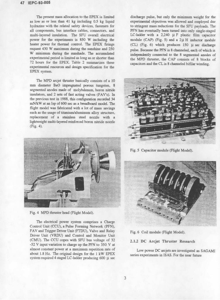
The present mass allocation to the EPEX is limited discharge pulse, but only the minimum weight for theas low as or less than 41 kg including 0.5 kg liquid experimental objectives was allowed and employed duehydrazine with the related safety devices, fasteners for to stringent mass reductions for the SFU payloads. Theall components, bus interface cables, connectors, and PFN has eventually been turned into only single-stagedmulti-layered insulation. The SFU overall electrical LC-ladder with a 2,240 p F plastic film capacitorpower for the experiments is 850 W including the module (CAP) (Fig. 5) and a 21 H inductor moduleheater power for thermal control. The EPEX firings (CL) (Fig. 6) which produces 150 p sec dischargerequest 430 W maximum during the sunshine and 250 pulse. Because the PFN is 8 channeled, each of which isW minimum during the sunshade. The accumulated independently connected to the 8 segmented anodes ofexperimental period is limited as long as or shorter than the MPD thruster, the CAP consists of 8 blocks of72 hours for the EPEX. Table 2 summarizes these capacitors and the CL is 8 channeled bifilar winding.experimental resources and design specification for theEPEX system.
The MPD arcjet thruster basically consists of a 10mm diameter BaO impregnated porous tungsten, 8segmented anodes made of molybdenum, boron nitrideinsulators, and 2 sets of fast acting valves (FAV's). Inthe previous test in 1988, this configuration recorded 34mN/kW at an Isp of 600 sec as a breadboard model. Theflight model was fabricated with a lot of mass savingssuch as the usage of titanium/aluminum alloy structure,replacement of a stainless steel nozzle with alightweight multi-layered reinforced boron nitride nozzle(Fig. 4).
Fig. 5 Capacitor module (Flight Model).
Fig. 4 MPD thruster head (Flight Model).
The electrical power system comprises a ChargeControl Unit (CCU), a Pulse Forming Network (PFN),FAV and Trigger Driver Unit (FTDU), Valve and Relay Fig. 6 Coil module (Flight Model).Driver Unit (VRDU) and Control and Monitor Unit(CMU). The CCU copes with SFU bus voltage of 32 2.1.2 DC Arcjet Thruster Research-52 V input variation to charge up the PFN to 350 V atalmost constant power at a maximum repetition rate of Low power DC arcjets are investigated as SAGAMIabout 1.8 Hz. The original design for the 1 kW EPEX series experiments in ISAS. For the near futuresystem required 4 staged LC-ladder producing 600 p sec
3

IEPC-93-005 48
without thermal drift was developed for the thrustmeasurements. SAGAMI-II was designed for 500 W
class intermittent pulsed mode arcjet thruster as well asthe steady-state. In ISAS spin stabilized satellites withside-mounted thrusters are popular and they requiresynchronized thrust generation with the rate of spinmotion. SAGAMI-II was developed for intermittent
2 3 4 5 cm firing thruster with 2.5 sec ON and 7.5 sec OFF cycle. 4
I i 1 ___The key technology is the quick start within 0.2 sec andcut-off within 0.3 sec using choked orifices and anelectromagnetic valve for N2 +2H2 propellant feed (Fig.
_ 7). Erosion rate of cathode and anode were decreased toS0, c so > 1.7 p1 g/C under the above on-off cycle operation. The
8 20 L L,=. , ........ ... 300. . steady-state thrust performance was also demonstratedS200 > using 0.3 mm diameter constrictor in Fig. 8. In this
3 00 1n on Po er Off
150
100 .oclowe
§0 01-- - , 2.00 0.5 1.0 1.5 2.0 2.5 3.0 M\ _ 1 1 2 - 1 .
Time . sec C'coswI/tj a vaa 1.5 ....... ................ ........................ - ... ... ........... .......................... .................... .....
Fig. 7 SAGAMI-II arcjet and intermittent operation(N2+2H2). e 1\ SHigh Voltage mode
c 1.0S Low Voltage mode c-0.5
5 , 1.032 ~.. =1.0
SAGAMI-Il 15mg/s 05 .--. . *----- ... ... ..... ........
600 - 0.3x0.5- --15mg/s 20
0.0550 . ....... 20 o.o . ... 1.0550 6 . 1.2 1.4 1.6 1.8 2.0
Non Dimensional Characteristic Are Lengt:S30 30
E 500 Fig.9 Chart of mode coefficient vs. nondimensionalizedO characteristic arc length (c:constrictor length to
' 450 diameter ratio).
400 SAGAMI-I As the basic research it is of interest to explain the.0-5x0.5 behavior of positive are column under practical ranges of
350 . . arcjet operation. A very simplified analytical model of200 400 600 800 1000 1200 1400 arc column behavior (CFA model: Cross Flow Arc
Input Power, W model) was established using the thermal diffusivity andthe flow velocity in the constrictor region.6 This
Fig. 8 SAGAMI series steady-state thrust performance theory explains the anode attachment of the arc such as(N2 +2H2 ). low voltage mode and high voltage mode which are the
most important physical phenomena in the DC arcjetscientific missions as well as basic researches very low thruster. Figure 9 shows the relation of voltage modepower range has a keen interest. SAGAMI-I was coefficient vs. non-dimensionalized characteristic arcdesigned and incorporated in regenerative cooling and length expressed by a parameter of constrictor length-to-0.5 mm diameter constrictor as the baseline model of 1 diameter ratio. This theory is useful for the designkW class arcjet thruster.3 A very accurate thrust stand
4

49 IEPC-93-005
guideline of arcjet thrusters as well as the explanation of current pattern were examined.7 Figure 11 indicates thatexperimental results to date. the CD anode geometry has better thrust efficiency than
flared anode for both H2 and Ar propellant. This wasdone by the strong concentration of the discharge currentto the throat portion, even in a molecular propellant,H2, and resulted in short-path discharges. In fact the lowIsp range the CD configuration generates the samethrust as the flared configuration but indicates lowerdischarge voltages. In the high Isp range the CDconfiguration produces similar thrust performance to theflared due to the current path diversity accompanying a"cathode jet".
The above phenomena were analyzed by quasi-one-dimensional flowfield model.8 Assumptions are fullyionized and ideal gas, only self-induced magnetic field,and constant electrical conductivity, etc. Non-dimensionalization and after some manipulation of total
2 - 0 100% pressure, P*, and total enthalpy, h, including magneticSQ energy contribution, a magnetosonic choking equation
is obtained. Since the propagation speed of smallFig. 10 Discharge of CD type 2-dimensional MPD disturbances is the magnetosonic speed in this sort ofarcjet (upper), and current contour measured by magnetic MPD flowfield, the plasma flow and the magnetic fluxsensitive film (lower) with Ar. is choked at the "throat" area. This tendency was
confirmed by different quasi-one-dimensional geometries
Ssuch as straight, flared, and CD. The analysis showed,30mN/kW O I the magnetic pressure steeply decreased at the throat of
30o a 0mN/kW CD configuration, and hence the strong current2 - / concentration occurs.20I
6 Y - Ar H,4 - a vrgO Convergent-Divergent Radiation Shade
h is /o lA flared0 0 straight
Fig. o Thrust performance comparisons of straight, Ignition Elect
flared, and CD channel geometries for H2 and Ar. Anode Tern
2.1.3 MPD Arcjet Research n sagCathde(BaSater Cooled Tube
In the historical point of view MPD arcjets Insulator Dis
employs a convergent-divergent (CD) anode for thedischarge chamber, however, the physical role of such a Fig. 12 Quasisteady MPD thruster head for periodical"throat" is not fully understood except for the empirical Operations.knowledge of relatively good performance or operationalstability. By virtue of 2-dimensional arcjet of which 2.2 Osaka Universitygeometry follows after the cross-section of coaxial MPDthruster (Fig. 10) its thrust performance and discharge 2.2.1 Quasisteady MPD Arcjet Research
5

IEPC-93-005 50
mixture of N2 +2H2 showed that there was the optimumA quasisteady MPD thruster periodical operations, axial field intensity with which the maximum thrust
as shown in Fig.12, were demonstrated in 1-kW-class was achieved for each gas, although at low dischargeaverage input power levels, i.e., in 1-MW-class input current levels for H2 and Ar the thrusts increased withpowers during arc discharge.9 Powers deposited into the the axial field intensity. The discharges for all gaseselectrodes and plasma flow were measured calorically, were inclined to occur more upstream with an increaseand the energy balance was examined. The fractions of in the axial field intensity. It was inferred that thesethe input power lost to the anode for N2 /H2 mixtures effects of axial magnetic fields on the performanceand H2 decreased from 40 to 30 % with increasing total characteristics and the arc feature were due to the rotatinginput power below the limiting discharge current motion of -Jr x B, that is, swirl acceleration andalthough for Ar it increased from 40 to 50 %. On the enhanced thermalization. In addition, an electromagneticother hand, the fractions deposited into the cathode particle-in-cell computation code was developed todecreased from 15 to 10 % for the mixtures and H2 and simulate numerically a collisionless MPD thrusterfrom 30 to 25 % for Ar. Thus, the energy balance plume released in a magnetized vacuum.1 3 Thecharacteristics depended on propellant species and simulation results showed that the axial magnetic fielddischarge current levels. Also the thermal analytical was weakened on the plasma boundary near the thrusterresults showed that only cathode tip was very severe in exit with a diamagnetic current.10-kW-class average power operations.
2.2.2 Low Power DC Arcjet DevelopmentGAS PORTS
The research program has been focused on the1 2 3 5 16 7 8 9 1.0 1 12r 13 1 5 development of a 1-kW-class hydrazine arcjet propulsion
S. - . - system for application to the north-south stationkeepingS........... for geosynchronous communication satellites, in
S-- - cooperation with Ishikawajima-Harima Heavy IndustriesI II Co. Ltd. 14 The radiation-cooled arcjet thruster RAT-V
was operated at power levels of 0.5-1.0 kW with50mm hydrazine decomposition products as the propellant
using a 50-kHz PWM power supply incorporating aFig. 13 Quasisteady MPD arcjet with 30-cm-class long high-voltage pulsed starting circuit. Stable, reliableelectrodes. long-term operations at specific impulse levels of 430-
530 sec, as shown in Fig.14, were demonstrated. TheAn MPD arcjet with 30-cm-class long electrodes as on-off tests of 100 times, with a thermally-severe
shown in Fig.13, i.e., with a long acceleration zone repetitive condition of 2-hrs firing and completealmost realizing a one-dimensional channel flow, was cooling, were conducted to examine the durability of thedeveloped to investigate the arc behavior and the whole thruster body. On the base of the results, aacceleration mechanism in MPD discharge prototype thruster system was designed for practical usechambers. 10 ,1 1 It was found that the tendency of the in space. Also the influence of the diameter andcurrent pattern was independent of electrode length and material of the cathode on the thrust performance andthat the feature on current conduction below the electrodes erosion was investigated. The 30-hrstheoretical critical current was classified into two cases, endurance tests showed that the axial rate of reduction ofdepending on monatomic and molecular gases. These a 4-mm-diameter W-ThO2(2%) cathode decreasedexperimental results agreed with those of one- drastically compared with that of a 2-mm-diameterdimensional MPD flowfield analyses. Also in the cathode made of W-Th0 2 or CeO2 (l%).transition to a quasisteady current pattern at thedischarge start, the motion of a current sheet was 2.23 Medium Power DC Arcjet Researchexamined.
10-kW-class water-cooled nitrogen-arcjet flowfieldsAn applied-field MPD arcjet has been studying to have been studying by means of spectroscopic
clarify the influence of axial magnetic fields on the diagnostics. 1 5 The atomic electron excitationthruster performance and the discharge feature. 12 An temperature and the electron density in the constrictorincrease in the axial field intensity raised the discharge increased from 15,000 to 18,000 K and from x 1015voltages at constant discharge currents below the to 2x 1016 cm 3, respectively, with the input powerlimiting current. The thrust characteristics for H2 and level of 7-11 kW. An increase in the mass flow rate
6
51 IEPC-93-005
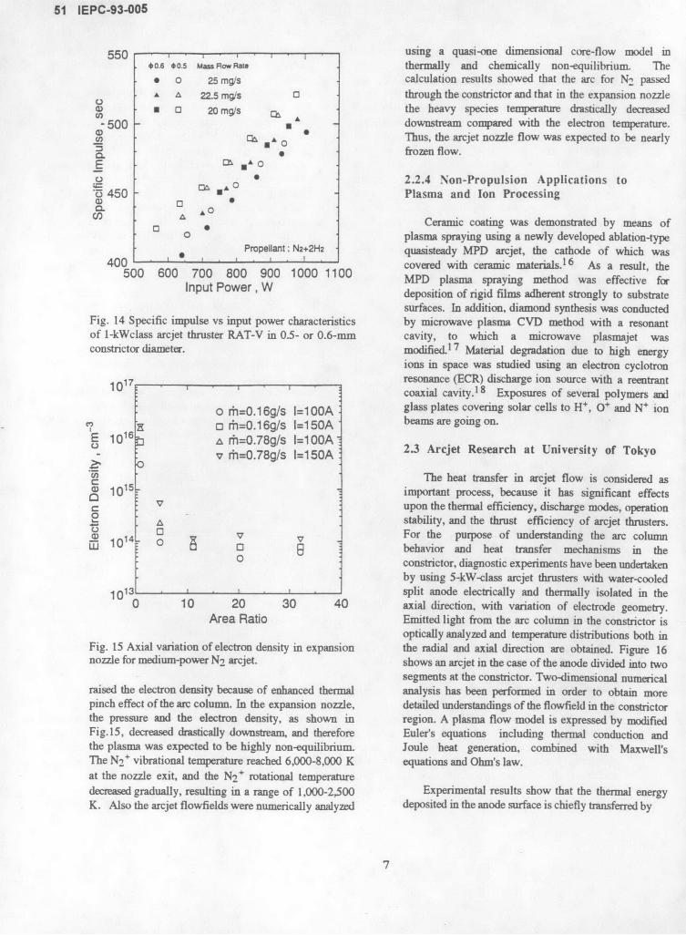
550 , , , . using a quasi-one dimensional core-flow model in*0.6 0.5 MassmFowRa thermally and chemically non-equilibrium. The0 o 25 mg/s calculation results showed that the arc for N2 passedA A 22.5 mg/s o through the constrictor and that in the expansion nozzle
a) S 0 20 mg/s the heavy species temperature drastically decreased- 500 - downstream compared with the electron temperature.
Ch A 0 Thus, the arcjet nozzle flow was expected to be nearly* frozen flow.
E ,A O
o 0 2.2.4 Non-Propulsion Applications to'5 450 - Plasma and Ion Processing
C * Ceramic coating was demonstrated by means ofo plasma spraying using a newly developed ablation-type
Propellant: N2+2H2 quasisteady MPD arcjet, the cathode of which was400 , 0 7 I I 11 0 covered with ceramic materials. 6 As a result, the
500 600 700 800 900 1000 1100 MPD plasma spraying method was effective forinput Power , W deposition of rigid films adherent strongly to substrate
surfaces. In addition, diamond synthesis was conductedFig. 14 Specific impulse vs input power characteristics by microwave plasma CVD method with a resonantof 1-kWclass arcjet thruster RAT-V in 0.5- or 0.6-mm cavity, to which a microwave plasmajet wasconstrictor diameter, modified.17 Material degradation due to high energy
ions in space was studied using an electron cyclotron
117 resonance (ECR) discharge ion source with a reentrant0 coaxial cavity. 1 8 Exposures of several polymers and
0 ri=0.16g/s 1=100A glass plates covering solar cells to H', O+ and N+ ionSo rhi=0.16g/s l=150A beams are going on.
E 1016' A r=0.78g/s I=100Aov r=0.78g/s 1=10A 2.3 Arcjet Research at University of TokyoS ovrh=0.78g/s 1=150A
C The heat transfer in arcjet flow is considered asS1015" important process, because it has significant effects
S v upon the thermal efficiency, discharge modes, operationSA stability, and the thrust efficiency of arcjet thrusters.
Jo For the purpose of understanding the arc columnM 101 0 behavior and heat transfer mechanisms in the
o constrictor, diagnostic experiments have been undertakenby using 5-kW-class arcjet thrusters with water-cooled
10o ' : 13 split anode electrically and thermally isolated in the0 10 20 30 40 axial direction, with variation of electrode geometry.
Area Ratio Emitted light from the arc column in the constrictor isoptically analyzed and temperature distributions both in
Fig. 15 Axial variation of electron density in expansion the radial and axial direction are obtained. Figure 16nozzle for medium-power N2 arcjet. shows an arcjet in the case of the anode divided into two
segments at the constrictor. Two-dimensional numericalraised the electron density because of enhanced thermal analysis has been performed in order to obtain morepinch effect of the arc column. In the expansion nozzle, detailed understandings of the flowfield in the constrictorthe pressure and the electron density, as shown in region. A plasma flow model is expressed by modifiedFig.15, decreased drastically downstream, and therefore Euler's equations including thermal conduction andthe plasma was expected to be highly non-equilibrium. Joule heat generation, combined with Maxwell'sThe N2 + vibrational temperature reached 6,000-8,000 K equations and Ohm's law.at the nozzle exit, and the N2
+ rotational temperaturedecreased gradually, resulting in a range of 1,000-2,500 Experimental results show that the thermal energyK. Also the arcjet flowfields were numerically analyzed deposited in the anode surface is chiefly transferred by
7

IEPC-93-005 52
thermal conduction of the gas, and by electrons which Central Research Laboratory, Mitsubisi Electricare accelerated in the anode potential drop. 19 It is found Corporation.that the anode heat loss can be reduced when the arcattachment is located downstream of the constrictor, In a previous study,2 0 the Euler equations werebecause a relatively cold gas envelope with low applied to simulate the flow in the arcjet thruster, soconductivity is formed around the arc column in the that a boundary layer developed on the thruster nozzleconstrictor, working as the thermal insulator between wall and hence the heat transfer towards the nozzle wallthe centered high temperature plasma core and the anode were not considered. However, an actual arcjet thrustersurface. Improved propellant injection, by which the which will be operated in space is radiation cooled.propellant gas is tangentially injected close to the anode Therefore, we have to consider irradiated energy from thewall so that a thick cold gas envelope can be wall. This consideration has been included into the wallestablished, is found to thermally pinch the arc column, boundary condition, namely the heat transferred towardswhich eventually increases the thermal efficiency, the wall is set to be equal to the radiation energy
released from the wall. Therefore, we need to employ theNavier-Stokes equations as the governing equations.Thus, numerical simulations of a low power DC arcjet
Propellant for outside injection thruster with argon as working gas, which has the samePropellanl for inside injection |.opll for insidinj Anode cooling water geometry as used in laboratory experiments,2 1 have
Cooling water ou t Anode been performed using the Navier-Stokes equations. Thethode adjusier/ gmenu flow equations are coupled with electric field equations.
SFigure 17 shows the constant temperature contourstogether with the positions of a maximum temperature,
Tuns-"en maximum anode temperature and maximum cathodetemperature. The propellant gas enters the thruster at a
Stemperature of 300K and then temperature is increaseddue to Joule heating. The maximum temperature in the
ooling water in flow is 8660K and it is seen upstream of the constrictor.Inutor o-ing TbWchode The detail of computation and results is described inInsulator O-ring ThW cathode
Ref. 22.
Fig. 16 DC arcjet with split anode.Tw =300 K 2T a 380 K
Numerical results have revealed a certain aspect of Iarc column behavior and how the arc length is Tu. = 8660 Kdetermined. In contact with the arc column, the cold gasenvelope is gradually heated due to thermal conductionas it flows downstream in the constrictor, after whichthe gas temperature becomes high enough to let thecurrent attach to the anode wall. The heat transfer fromthe arc column is subject to thermal conductivity Tcharacteristics of the gas, while the specific heat anddensity dominate the temperature increase, which in turncontrols the electric conductivity increase along with the Fig. 17 Computed arcjet flowfield.axial positions.
2.5 MPD Thruster Research at Tokai2.4 Arcjet Research at Kyushu University University
In order to predict the performance characteristics of A numerical simulation of one-dimensional flowsarcjet thruster, the detail of the flow field inside the in self-field magnetoplasmadynamic (MPD) thrusters isthruster is required. For this purpose, computational performed taking thermal and ionization nonequilibriumsimulations of the thruster flow field have been state into account. 2 3 The model used includes theconducted at Department of Aeronautics and electron energy and ionization rate equations and isAstronautics, Kyushu University in cooperation with referred to as a two-temperature model. In the paper
presented in this conference, the calculated results based
8

53 IEPC-93-005
on this model are compared with those based on the one- high enthalpy condition. The electrically dischargedtemperature model in which the electron temperature is arcjet contains enormous energy, and therefore highthe same as the heavy particle temperature although temperatures, high velocities and high ionizations.ionization process is involved. It is found that: Then DC arcjet, which was developed to do experiment1) the onset current for the one-temperature model is for electric propulsion, is used to simulate such mainlarger than that for the two-temperature model at any stream (in this case, test gas is argon), and encountermass flow rate (Ar) in the range of 0.01-lg/s under a with fuel jet (which is simulated by argon gas withspecific configuration, 2)the variation of H (distance heated Iodine, 12, vapor), each other at right angle.between plane electrodes) under a given discharge current Iodine vapor is seeded for visualization by LIFdoes not cause any change in the flow characteristics, technique. With that technique, fluorescent light, whichwhen FO (mass flux) is adjusted to keep a fixed value, is emitted from Iodine molecules under the existence ofand the variation of L (channel length), under usual their special wave length laser light, shows structure ofMPD thruster flow conditions, does not cause noticeable injected fuel jet.change in the value of onset current, for given values ofH and mt (mass flow rate), 3) the sonic point for thetwo-temperature model exists very near the inlet ofthruster compared to that for the one-temperature model,4) as for the electromagnetic operation, in both modelsthe input power is spent chiefly on ionization ofpropellant in low discharge current levels and onacceleration in high discharge current levels and 5) alowering of the thrust density due to ionization appearsin the region of low current levels for the two-temperature model.
2.6 IPD Thruster Research at TohokuUniversity
At Institute of Fluid Science, Tohoku University,theoretical works on electromagnetic/static/thermal Fig. 18 Interaction of two jets.thrust production are conducted. Results that haveobtained are as follows:2 4 -2 6 Argon gas simulating air (10ml/sec) is introduced
from a gas cylinder (held at 1.5 - 2.0 x 10⁵ Pa) to an1.Thrust formula of electromagnetic/thermal acceleration arcjet thruster; it is electrically discharged (40 V and 100has been obtained. A normalized velocity is expressed - 150 A) to give high enthalpy and velocity, and isusing three characteristic parameters; (1) exhausted as a hypersonic flow into the low density(i 0o / J m) / u (po,; permeability in vacuum, wind tunnel. Another argon gas simulating hydrogen
fuel is su lied from another gas cylinder (held at 1.5 -JD;discharge current, mt;mass flow rate, Uno Alfven's ischarge Alfven's 2.0 x 1 Pa) to the wind tunnel, through a containercritical velocity) (2) Bz / Be (ratio of an applied to filled with heated Iodine vapor and a sonic nozzle. Theinduced magnetic fields) and (3). TF (electron Hall wind tunnel is evacuated down to 0.6 - 1.3 x 10² Pa byparameter). an oil rotary pump. Geometrically speaking, the arcjet2.Hall acceleration is generalized by combining with thruster and sonic nozzle are placed in a vertical planethermoelectric effect caused by electron pressure identical to the laser sheet. Argon ion laser (514.5nm,gradient. At a constant exhaust velocity, this effect was CW, over 1600mW output, Imm diameter) is deformedfound to decrease discharge voltage. into sheet, using two cylindrical lenses (convex and
concave), and is guided to the plane via a special optical2.7 Nagoya University system in green range, not to reduce the laser power. A
camera with a macro-lens and special optical filter,DC arcjet as a main flow of air breathing engine which allows only the wavelength of Iodine fluorescence
In this study, it is highlighted that mixing and to reduce background light, set perpendicular to the laserinteraction of main flowfield of air and fuel jet for sheet, takes photographs with high-iso black-and-whitescramjet engine. So, mainflow needs steady hypersonic and color films. One of those is shown as Fig. 18; a
barrel shock and a Mach disc can be seen. But in many
9

IEPC-93-005 54
cases, eye observation could catch the turbulent flow 2.9 Ishikawajima-Harima Heavy Industriesfeatures where the flow was strongly oscillating. The Co. (IHI)reason is given below. Argon positive ion hascharacteristic wavelengths for emission determined from IHI has been developing and supplying exclusivelyquantum mechanics, but electron has no such particular reaction control system for NASDA's rocket andwavelengths, and therefore the jet emits continuous satellites. Fundamental studies of electric propulsionlight. Thus, the arcjet can be recognized by itself even have been carried out for improving performances ofif the optical filter is used. So, more studies are needed. Electrothermal Hydrazine Thrusters (EHTs), MPD arcjet
thrusters and DC arcjet thrusters and for manufacturingflight models of the former two.
2.8 MPD Flow Analysis at HokkaidoUniversity 2.10.1 EHT
Department of Electrical Engineering, Hokkaido Two sets of EHT thruster subsystems wereUniversity has investigated computational methods for developed and passed the acceptance tests forthe numerical analysis for the two dimensional MPD Engineering Test Satellite VI (ETS-VI) under thearcjet thrusters. 2 7 Recently, a new computer code based NASDA contract. The satellite is planned to be launchedon the finite difference method has been developed.2 8 In by Japan's new rocket H-II in summer 1994 and thethe code, the plasma flow in the thruster is determined EHT will then start experimental operation of thefrom the conservation laws of mass, momentum and North-South station keeping for two years. MI willenergy. The magnetic field, which is induced by the support the EHT operation program and analyze flightcurrent flowing in the plasma and has a sufficiently data to evaluate the performance.shorter characteristic time compared to the plasma flow,is assumed to be governed by the static induction 2.10.2 DC Arcjetequation. The code employs the explicit TVD (TotalVariation Diminishing) scheme for the solution of the IHI has put emphasis on developing 1 kW-class DCplasma flow involving a shock wave and the SOR arcjet systems, considering to be applied for the near(successive over-relaxation) for the magnetic field. A future space programs. In collaboration with Osakatypical numerical result is shown in Fig. 19, in which University, parametric studies have been conducted onconcentration of the mass density contours obviously thruster dimensions and propellant gas properties. Theindicates existence of the shock wave. Moreover, the thrust performance achieved from the former study has acode is shown to give the current-thrust characteristics specific impulse of more than 500s at an input power ofconsistent with the experimental results measured in 900 W.1 4 Further studies on performance improvementISAS. A code for the axisymmetric MPD thrusters is have been carried out, using a gas mixture simulatingnow under developing. hydrazine decomposed products in actual state. The
thrust and lifetime performance of DC arcjet system willbe investigated until the end of this year.
2.10.3 MPD Arcjet
The flight model of the 1 kW-class MPD arcjet[X10-4Kg/m3] thruster, shown in Fig. 20, and propellant supply
0.10 subsystems for SFU-1 have been shipped to ISAS. 2
0.24 Acceptance tests, including EMI test and a hydrazinedumping test, were successfully completed. A result ofEMI test is shown in Fig. 21, which indicates that theemission strength exceeds the standard requirements butstays safely within the permissible level of SFU.Studies on reducing the emission is now continued.
The research on performance improvement has beenFig. 19 Computed mass density contours. also lasted with the Ikw-class projected anode MPD
thruster.2 9 A thruster of the same type achieved a
10

55 IEPC-93-005
thrust efficiency of over 30% at a conventional anode- A feasibility study on steady state 100 kw-class
embedded wall type by ten per cent. thrusters using superconducting technology wasperformed to reveal its probability to realization. In thesystem a superconducting coil will be employed togenerate applied field, herium and hydrogen will be usedas cryogen and propellant. A total impulse generation of5 x 109 Ns was estimated.
3. ION PROPULSION
3.1 National Space Development Agency ofJapan (NASDA)
SlNASDA has been developing a 20 mN class ion.1 1| -* . engine system (IES). It will be utilized for North-South
S " Station Keeping ETS-VI and COMETS. As for the IESSfor ETS-VI, Flight Models of TRS (Thruster) and MFC
Fig. 20 Flight model of 1 kW-class MPD arcjet. (Mass Flow Controller) are under combined AcceptanceTest now. Other flight components were already handedinto ETS-VI system after Protoflight Test or AcceptanceTest. FM TRSs and MFCs will be clustered and are
EISO LEV Iu idelivered to ETS-VI system next year. ETS-VI is'W" L-M 4C -s ae scheduled to be launched in summer next year. The
MALn .i, result of TRS Acceptance Test shows satisfactory,0am u,, 4performance regarding specifications such as thrust
range(18.6 to 27.9 mN), ignition time, transient thrustand neutralizer characteristics. The same thruster will be
o used for COMETS launched in 1997 and manufacturingof IES components began recently.
Endurance tests were carried out for MFC sensor,MFC valve and TRS hollow cathode. There was noproblem. As for the endurance test of TRS, the status isas follows.
.01 1 BBM : finished after 9,000 hours.2 DMs : finished after 7,000 hours.
S4 EMs : 6,000 to 8,000 hours under test
to MzsSw IO [ e v2 2 PMs : 4,000 hours under test
.I O swu SnSC! Main characteristics of the IES components are asfollows.
TRS(thruster)Thrust: 18.6 to 27.9mN (nominal 23.3mN)
__ Isp : 2,900 sec.Life time: 6,500 hoursOn/off Cycle : 2,900 cycles
,0 Time needed for ignition : < 5 min.______Input Power: 600 W (at nominal thrust)
S | | | Weight: 2.7kg
- MFC(mass flow controller)Fig. 21 EMI test results. Mass fow rate : 0.2 to 5.0 seem for Hollow cathodes
11

IEPC-93-005 56
0.4 to 10.0 sccm for Main discharge chamber On the other hand, in order to verify the life time ofPower dissipation : 9 W ion thrusters, the endurance tests using 4 engineeringWeight: 0.9 kg model(EM) thrusters and 2 prototype model(PM)
thrusters are carrying on at Tsukuba Space Center ofPMU(propellant management unit) NASDA. As of July 1993, approximately, 6,000-8,000
Propellant: xenon hours ON/OFF operations for 4 EM thrusters andStorage capacity : 20.5 kg (100kgf/cm 2 ) approximately 4,000 hours successive operations for 2Outlet pressure : 0.8 to 2.7kgf/cm 2 PM thrusters have completed. These life-test data showWeight: 10.3kg that thruster operation and its performance are stable
during these tests period. In this endurance tests, thereIVDE(ion engine valve driving electronics) is an interference of neutralizing current when two or
Weight : 1.2kg more thrusters are simultaneously operated. To researchthis phenomenon, extended tests are performed using
TCU(thruster control unit) two neutralizer hollow cathodes and two thrusters. ByPower dissipation: 10 W these tests, it is proved that the amount of theWeight: 7.8 kg neutralizer emission current strongly relates to the space
chamber potential (beam target potential) and the ratioPPU(power processing unit) of imbalance depends on the propellant feed rate supplied
High voltage : 1.0 to 1.2 kV to the each neutralizer So, the neutralizing current canMain discharge current : 2.0 to 4.0 A be controlled via neutralizer mass flow rate control.Power dissipation : 120 WWeight: 10.0 kg 3.2.2 In house development model
3.2 Mitsubishi Electric Co. (MELCO)
3.2.1 Ion Engine for ETS-VI -
MELCO has been developing Ion enginesubsystem(IES) for north-south station keeping ofEngineering Test Satellite VI (ETS-VI) under thecontract of NASDA. ETS-VI is a three-axis controlled,geosynchronous satellite of 2 ton class, and its missionlifetime is 10 years. IES consists of the followingcomponents.
1. Two Ion clusters(integrated 2 Ion thrusters and 2Mass flow controllers on bracket): ITRS
2. Two Propellant Management Units : PMU3. Four Power Processing Units : PPU4. One Thruster Control Units: TCU5. Two Ion Engine Valve Drive Electronics: IVDE6. Four Ion thruster Contamination Shields
The status of this program is in the system interfacematching test(Acceptance Test of system level) forprotoflight models, such as TCU / PPU / PMU / IVDE/ ICNS. And the ion thrusters and the mass flowcontrollers as the flight models are completed theperformance and the environmental tests (component Fig.22 25mN- and 150mN-class ring-cusp ion thrusters.AT). Results obtained during these tests are fairlysatisfactory and the interface matching of IES among MELCO has also been developing cusp type ioneach IES component and in the ETS-VI satellite system thruster for future programs, such as the Orbital Transferwere confirmed. Vehicle or Geostationary Platform control. Figure 22
shows the 25mN class and 150mN class ring-cusp type
12

57 IEPC-93-005
ion engine thrusters. The performance of these thrustersare as follows.
25mN thruster 150mN thrusterion production cost(eV/ion) 231.5 * 100 **propellant utilization (%) 92.0 * 95.0 **
(* mesured value , ** design goal value)
3.3 Toshiba Corporation LLOo DSCHARGECATHODE
CHAMBER
Since 1983, Toshiba Corporation has been ACCELERATOR RIdeveloping a power processing system for a 20mN class ATSion thruster, which is adopted to a north-south ISOLATOR PROPELLANTstationkeeping of ETS-VI, based upon the contract with DISTR
NASDA. The power processing system consists of athruster control unit (TCU) and four power processingunits(PPU). l
The TCU simultaneously operates two PPUs and SHIELDING CASEtwo valve drive electronics(TVDE) corresponding to twoion thrusters. The TCU controls the eight power supplyunits of the PPU in accordance with a sequential logicflow. The TCU has an internal redundancy and uses 8- Fig. 23 NAL 14-cm diameter ring-cusp xenon ionbits micro processor as the CPU to control the thruster.sequential logic flow and to process magnitudecommands and a plenty of telemetry.
37
The PPU contains the eight power supply units for 3a 35
the thruster operation. The high voltage power for the -- Grid-set 1 34screen grid and accelerator grid are generated by means of . -.- Grid-set 2 33a switching regulator which consists of boost choppers . -- Grid-set 3 - 32
regulator, a current resonant inverter and voltage ,31 >multiplying rectifier. The power supply units achieve -3the power efficiency over 85%. 29
- 28
Flight hardwares of one TCU and four PPUs are 27 "
fabricated. Component test and ion engine subsystem 2 26
test have completed. ETS-VI system proto-flight test 230 -has carried out with one TCU, two PPUs and two adummy thrusters. The function and performance of 8 220
power processing system were assured by means of -these tests. -"
- 200 -
3.4 National Aerospace Laboratoryz 190
Research activities on xenon ion thrusters for __80
auxiliary propulsion have been continued. Most of the so 90 100
efforts are presently focused on performance and PROPELLANT UTILIZATION EFFICIENCY s. (%)endurance improvement of ring-cusp ion thrustershaving a nominal thrust of 25 mN at the beam voltage Fig. 24 Thruster performance with different grid sets forof 1 kV. 30 ,3 1 ion-optics system.
The objective is to apply them to north-southstationkeeping of future geostationary satellites. Figure system of the 25 mN thruster was improved in an23 shows the latest model thruster. The ion-optics experimental study.3 0 Three grid sets were examined for
13

IEPC-93-005 58
the ion-optics system. Thruster performance plots withthese are shown in Fig. 24. One is the original grid set Besides these we are supporting the ETS-VI ion
(Grid-set 3). The other two are improved grid sets engine development. In particular, ion beam
(Grid-sets 1 and 2). The two are dished shallower, and characterization and contamination problems were
their hole pitches in the accelerator grids are closer to studied as a cooperative work with National Spacethose in the screen grids (Grid-sets 1 and 2). Thus, their Development Agency. 3 4
grid-hole compensation is smaller than in the originalone. Moreover, one of the two has an increased holediameter in a rim region of the accelerator grid (Grid-set 0: 6 36 >2).
2 : JACCEL /J(AW
No significant difference was observed in these three. 0. 5 a : VOlscHARGE 34
However, Grid-set 1 is the most preferable. The main Cdischarge with Grid-set 1 is the most stable among these <at the propellant utilization efficiency of 90 % for - 0. 4- 32 -
typical operation. The erosion of the accelerator grid >
holes due to excessive grid compensation is smaller in - 3Grid-set 1 than in the others. The thruster with Grid-set cr
1 achieved an ion production cost of 200 W/A and a -discharge voltage of 30 V at the propellant utilization 0. 2 28 8efficiency of90 %. 0 2 4 6 8 10 12
PRESSURE P (10 Pa)
An extensible thruster stand is installed in thevacuum facility at NAL. 3 2 This is to improve thevacuum environment for thruster operation while Fig. 25 Accelerator grid current and discharge voltageallowing easy access for replacing the thruster in a versus chamber pressure.vacuum. After a thruster is installed at the stand in thelock chamber, it is moved into the main vacuum 3.5 National Aerospace LaboratoryToshibachamber, where the pressure is much lower. CorporationExperiments were conducted to evaluate this function.3 3
Tests revealed that the pressure around the thruster was Research and development on 30 cm diameter ring-lowered to 1/2 - 1/3 by using this thruster stand. cusp xenon ion thrusters started as a cooperative work of
the National Aerospace Laboratory and ToshibaIn addition, thruster parameters were measured as the Corporation. The objective is to develop basic
chamber pressure P was changed intentionally by technology for future application to primary propulsionfeeding extra xenon. Figure 25 shows variation in the systems of orbit transfer vehicles. The thrusters wereaccelerator grid current JA and the discharge voltage VD. designed to produce a thrust of 150 mN and a specificExtrapolation of the JA plot gives JA value at P = 0, impulse of 3500 s at an exhaust ion beam energy of 1and error estimation in the JA measurement. Then the keV.
JA measurement error is estimated at 0.05 % for noextra xenon feeding corresponding to the left-most data The first laboratory model LM-1 (Mark-I and Mark-point. 2) operated successfully in thrust and specific impulse
performance. Performance tests showed an ionA collimating E x B momentum analyzer probe production cost of 178 W/A and a discharge voltage of
was designed to measure the ratio of doubly to singly 39 V at the propellant utilization efficiency of 90 %.35charged ions J"+/J+ in the exhaust beam of a thruster.The probe has a mass separator arranging an electric The second laboratory model LM-2, shown in Fig.field perpendicular to a magnetic field and both 26, is the same as the Mark-2 thruster except theperpendicular to the ion velocity. Various probe magnetic field in the discharge chamber and the supportsconfigurations were constructed by changing some of of the ion accelerator grid system. The LM-2 thrusterthe probe parts. Each configuration was tested to has 3 magnet rings of Sm2Col7 and 12 grid supportimprove the separation between ion currents of both springs of piano wire. Performance tests showed anspecies. The probe was traversed across the ion beam to ion production cost of 168 W/A and a discharge voltageprovide radial distribution of J/J*. of 30 V at the propellant utilization efficiency of 90 %.
14

59 IEPC-93-005
Propellan NeutralizerTank
Microw 20 30 gas ve cce cce gs
Beam -
Fig. ig. 27 Schematic diagram of ECR ion thruster system,YOSHINO series.
o to cm 20 30 gas gwave accel accel wave gasI,,,. .. . ,,,,,,,, I ,,,,,,. J on off o
Fig. 26 NAUToshiba 30-cm diameter ion thruster Current,Laboratory Model-2. mA o
- ' *-- __-__
In Sections 1 and 2, the ion production cost is Accel 1defined as the main discharge power divided by the ion Voltage,beam current. The propellant utilization efficiency is kV ofor the discharge chamber, and does not contain thepropellant to the neutralizer.0 wave lasma S ce
3.6 Microwave Ion Thruster Research at o NeutralizerISAS
Xenon 2 |The electron cyclotron resonance (ECR) discharge seem
ion thruster,3 6 ,3 7 YOSHINO series, developed in ISAS 0has the following features. o 40 s8 120
Operation Time, sec1) A single microwave generator feeds power to both Fig. 28 Time profile of system operation ona main plasma source and a neutralizer, YOSHINO-4 ion thruster.2) The thruster system is operated without thermo-
emissive cathodes, originated from the thermal electrons besides thermo-3) A propellant feed system is simplified using a emissive electrons. The needless of the thermo-emissive
single flow controller. cathode will solve several malfunctions annoying theelectron-bombardment ion thruster. The thruster system
Figure 27 shows the schematic diagram of the ion is simplified using a single controller for the plasmathruster system. The ECR discharge generates the generation. The microwae power and propellant areplasmas in the main plasma source and the neutralizer distributed to both the discharge chambers by fixedusing microwave and permanent magnet without dividers. The YOSHINO series ion thruster system has aelectrodes. The primary electrons with high energy are
15

IEPC-93-00 5 60
microwave generator, two DC power supplies for theion acceleration and a flow controller. These will down-size the ion thruster system in weight, components, andexpense, keeping the system reliability and robustness. / / V ' 5The integration test of YOSHINO-4 is under execution /'Jh/ , 4on the basis of the separate investigations on the -. 4'
thruster head and neutralizer. The preliminary operation 3was performed as seen in Fig. 28. The microwave 2power injection ignites both the plasmas in the plasmasource and the neutralizer simultaneously after thesupply of propellant gas. And the apply of acceleration Ivoltage executes ion acceleration and beamneutralization so that the signal of beam current ismeasured in consistent with the acceleration voltage in -rtime.
3.7 University of Tokyo
3.7.1 Cusped Ion Thruster Research 2
A two-dimensional particle-in-cell(PIC) code has 15been developed to calculate orbits of charged particles in /the magnetic cusp.3 8 This simulation was performed inorder to understand ion loss mechanism near magnets inthe discharge chamber of cusped ion thrusters.
This code is based on the electrostaticapproximation. It uses charged particles moving about -* "L ,-due to forces of their own electrostatic field and anapplied magnetic field. The electric field is calculatedfrom the Poisson's equation by knowing the positions Fig. 29 Computed ion density and potentialof all of the particles. The forces on the particles are distributions in the cusp region.found using the electric and magnetic fields in theNewton-Lorentz equation of motion. The ties from the 3.7.2 Hall Thruster Researchparticle position to the field are made by first assigningthe particle charge to the grid points. Once the densities Two-dimensional numerical model of plasma floware established on the grid, the Poisson's equation is in a Hall thruster 9 has been made to analyticallysolved by the Finite Element Method to determine the estimate the ion-loss flux to the walls of an accelerationelectric potential. One calculates the fields from the channel, and to obtain information about desirableinitial charge, then moves the particles and recalculates configuration for good thruster performance. The modelthe fields due to the particles at their new positions, is comprised of an electron diffusion equation and an ion
kinetic equation, which enables one to computeThis simulation enables us to calculate distributions electrostatic potential contours and ion-beam
of ion density and of space potentials as shown in Fig. trajectories. In the first step, ion-production distribution29. These profiles quantitatively agree with those was assumed. From the results, it was found thatmeasured by previous authors in the point that 1) the electric field distortion, which is a main cause of ionion density distribution has a large peak in the center of loss to the channel walls, is induced not only due to thethe cusp and becomes sharper with an increase in curvature of magnetic field lines, but also due to themagnetic field strength; 2) on the space potential radial non-uniformity of ion-production distribution. Indistribution, there exists a potential valley in the center the second step, the ion-production distribution was self-of the cusp. In addition, this code can be used to consistently determined by combining an energyexamine effects of magnetic field and wall anode conservation equation with the above two basicpotential and further to obtain information for equations. The results indicate that the profile of ion-improving ion confinement in the cusp region, production distribution largely changes with the
16

61 IEPC-93-005
magnetic field geometry, and hence the field geometrysignificantly influences the ion-loss flux to the channel The work described in this paper was carried out bywalls. The computed ion-loss fraction (a fraction of ions the members of Institute of Space and Astronauticalproduced that are lost to the walls) and profiles of Science, National Aerospace Laboratory, Osakaplasma properties show good agreements with the University, Kyushu University, and other universitiesmeasured ones.4 0 and companies. The author gratefully acknowledges
the contributions of these members.3.8 Tokyo Metropolitan Institute ofTechnology References
Preliminary experiments of C6 0 sublimation, 1. Toki, K., Shimizu, Y., Kuriki, K., Suzuki, H., andplasma production and its ion beam extraction using a Kunii, Y., 'Electric Propulsion Experiment (EPEX)RF ion thruster are carrying on, in order to apply the Onboard Space Flyer Unit (SFU)", Proceedings of the
C6 0 as the propellant.4 1 As Fullerene (C60 ) is solid 18th International Symposium on Space Technologystate (powder) in room temperature (sublimation and Science, Kagoshima, 1992, pp. 391-396.temperature: -700 K), sublimation equipment is needed 2. Toki, K., Shimizu, Y., Kuriki, K., Suzuki, H., andfor the supply in gaseous state and the estimations of Kunii, Y., "Development of an MPD Thruster Systemthe sublimation rate and mass flow control are for the EPEX Space Test", IEPC-93-058, Seattle,important factor for the practical application. Figure 30 1993.shows the typical result of the FTIR (Fourier Transform 3. Yamada, T., Shimizu, Y., Toki, K., and Kuriki, K.,Infrared Spectrophotometer) spectrum analysis for the "Thrust Performance of a Regeneratively Cooled Low-sublimated, collected powder and original powder Power Arcjet Thruster", Journal of Propulsion and(refined C6 0 : containing more than 85 % C6 0 ) enclosed Power, Vol. 8, No. 3, May-June 1992, pp. 650-654.
in the sublimation chamber. As shown in this figure, 4. Iwamoto, Y., Yamada, T., Shimizu, Y., Toki, K.,typical and featuring spectrum peaks of C6 0 such as and Kuriki, K., "Pulsed Operation of A Low Power
527.4 cm-1, 576.4 cm 1 , 1182.4 cm-l and 1428.5 cm 1 Arcjet, Proceedings of the 18th International
are revealed in the sublimated powder wave form as well Symposium on Space Technology and Science,
as in the original powder. This seems to be caused by Kagoshima, 1992, pp. 385-390.5. Yamada, T., Toki, K., Kuriki, K., Iwamoto, Y., andthe difference of the sublimation temperature between 5. aaa, ., rii, ., waoto, ., an
C6 0 and other contents (C70 , etc.,). Therefore, adequate Ogiwara, K., Intermittent Operation of a w PowerArcjet," IEPC-93-184, Seattle, 1993.
sublimation chamber enables the supply of the gaseous 6. Yamada, T., Tol, k., and Kuriki, K., "Behavior ofC6 0 to the discharge chamber. Using the sublimation. ri.
Arc Column in Arcjet Constrictor," IEPC-93-184,chamber for the gaseous C6 0 supply to the RF Seattle, 1993.discharge chamber, preliminary experiments on plasma 7. Funaki, I., Nakayama, T., Toki, K., Kuriki, K.,production and ion beam extraction have been conducted. "Magnetosonic Choking Control of MPD Arcjet,"
Proceedings of the 18th International Symposium on5764 142- Space Technology and Science, Kagoshima, 1992, pp.
S 527.4 1182.4 Onginal Powder 367-372.
Collected 8. Funaki, I., Toki, K., and Kuriki, K., "Role of AnodePow der Throat in MPD Arcjet," IEPC-93-120, Seattle, 1993.
< / 9. Yoshikawa, T., Kagaya, Y. and Tahara, H.," Energy-l Deposition in Quasisteady Magnetoplasmadynamic
Sp Arcjet," 23rd IEPC, 93-192, 1993.g 10. Yoshikawa, T., Tahara, H., Kagaya, Y. and
S ll' " " J Tsubakishita, Y"Performance Characteristics and< . -Current Distributions of Quasisteady
400 800 1.200 1.600 2,000 3,000 Magnetoplasmadynamic Arcjets," 2nd German-RussianWave Number, cm -Conf. Electric Propulsion Engines and Their Technical
Applications, Moscow, Russia, A2-15, 1993.Fig. 30 Typical result of FTIR spectrum analysis for 11. Tahara, H., Tsubaki, T., Kagaya, Y., Tsubakishita,sublimated, collected powder and original powder. Y. and Yoshikawa, T.," Diagnostic Experiment and
Numerical Analysis of One-Dimensional MPDAcknowledgments Flowfields," 23rd IEPC, 93-197, 1993.
17

63 IEPC-93-005 IEPC-93-005 62
12. Tahara, H., Kagaya, Y., Tsubakishita, Y. and 25. Sasou. A., "Thrust Production Theory onYoshikawa, T.," Performance Characteristics and Electromagnetic/hermal Hybrid Arcjets," 23rd IEPC,Discharge Features of a Quasisteady Applied-Field Seattle, 1993.Magnetoplasmadynamic Arcjet," 2nd German-Russian 26. Sasou, A., "Generalized Hall Acceleration," JournalConf. Electric Propulsion Engines and Their Technical of Propulsion and Power, to be published.Applications, Moscow, Russia, A2-13, 1993. 27. Sawai, S., Igarashi, H., Honma, T., Toki, K. and13. Matsumura, H., Tahara, H., Tsubakishita, Y. and Kuriki, K., "An Electromagnetic Field Analysis ofYoshikawa, T.," Electromagnetic Particle-In-Cell Two-Dimensional Arcjet Thrusters Using the BoundarySimulation of Plasma Thruster Exhaust Plumes," Int. Element Method," Int. J. Appl. Electromagnetics inSymp. Simulation and Design of Applied Materials, Vol. 1, 1990, pp. 319-326.Electromagnetic System (ISEM), Sapporo, Japan, Paper 28. Itoh, H., Funaki, I., Igarashi, H., Toki, K., Honma,No. F38, 1993. T. and Kuriki, K., "A Finite Difference Analysis of the14. Yoshikawa, T., Onoe, K., Tsuri, S., Ishii, M. and Two dimensional MPD Thruster," to be published inUematsu, K.," Thrust Performance and Life Evaluation the Proceedings of ISEM-Sapporo, 1993.of a Low Power Arcjet," 23rd IEPC, 93-086, 1993. 29. Ohtsuka, T., Uematsu, K., and Kuriki, K.,15. Tahara, H., Uda, N., Onoe. K.. Tsubakishita. Y. "Investigations on MPD Arcjet with Projected Anodes,"and Yoshikawa, T.," Optical Measurement and 20th IEPC 88-110, 1993.Numerical Analysis of Medium-Power Arcjet Non- 30. Hayakawa, Y., Miyazaki, K. and Kitamura, S.,Equilibrium," 23rd IEPC, 93-133, 1993. "Performance Test of a 14 cm Xenon Ion Thruster,"16. Tahara, H., Tsubaki, T., Kagaya, Y., Tsubakishita, AIAA Paper 92-3147, 1992.Y. and Yoshikawa, T.," Applications of Quasi-Steady 31. Kitamura, S., Miyazaki, K. and Hayakawa, Y.,MPD Arcjets to Material Processings - Ceramic "Cyclic Test of a 14 cm Diameter Ring-Cusp XenonCoatings by Means of MPD Plasma Spray -," 23rd Ion Thruster," AIAA Paper 92-3146, 1992.IEPC, 93-168, 1993. 32. Kitamura, S. et al., "Xenon Ion Thruster Test17. Tahara, H., Minami, K., Yasui, T., Onoe, K., Facility - Design and Operation," Proc. of IEPC 88-Tsubakishita, Y. and Yoshikawa, T.," Plasma 060, 1988.Generation by Resonant-Cavity Microwave Discharge 33. Miyazaki, K., Hayakawa, Y. and Kitamura, S.,and Its Applications for Material Processing," Jpn. J. "Extensible Thruster Stand to Improve VacuumAppl. Phys., Vol.32, No.4, 1993, pp.1822-1828. Environment for Ion Thruster Operation," NAL TR-18. Tahara. H., Yasui, T., Onoe, K., Tsubakishita, Y. 1198, April, 1993 (in Japanese).and Yoshikawa, T.," Microwave Ion Source Using 34. Takegahara, H. et al., "Beam CharacteristicsResonant Cavity," Jpn. J. Appl. Phys., Vol. 32, No. Evaluation of ETS-VI Xenon Ion Thruster," IEPC 93-3A, 1993, pp. 1298-1302. 236, 1993.19. Fujita, K. and Arakawa, Y., "Anode Heat Loss and 35. Yoshikawa, T., "Electric Propulsion Research andCurrent Distributions in DC Arcjets," IEPC 93-185, Development in Japan," IEPC 91-004, 1991.Seattle, 1993. 36. Kuninaka, H., and Horiuchi, Y., "Development of20. Nishida, M., Kaita, K., and Tanaka, K, "Numerical Ion Thruster System for Interplanetary Missions",Studies of the Flow Field in a DC Arcjet Thruster," IEPC 93-198, Seattle, 1993.Proc. 20th IEPC, Garmisch-partenkirchen, 1988, pp. 37. Kuninaka, H., and Ishikawa, Y., "Microwave591-597. Plasma Contactor", IEPC 93-040, Seattle, 1993.21. Tanaka, K., Tsuchiya, K., Kaita, K., and Nishida, 38. Hirakawa, M. and Arakawa, Y., "Plasma ParticleM., "Experimental Investigation on the Characteristics Simulation in Cusped Ion Thrusters," IEPC-93-242,of a Low Power Arcjet Thruster," Proc. 20th IEPC, Seattle, 1993.Garmisch-Partenkirchen, 1988, pp.620-626. 39. Komurasaki, K. and Arakawa, Y., "Tow-22. Okamoto, H., Nishida, M., Tanaka, K., and Dimensional Numerical Model of Plasma Flow in aBeylich, A., "Numerical Simulation of the Performance Hall Thruster," IEPC-93-230, Seattle, 1993.of a Radiation-cooled lkw DC arcjet Thruster, IEPC 93- 40. Komurasaki, K. and Arakawa, Y., "Hall Current181, Seattle, 1993. Ion Thruster Performance," Journal of Propulsion and23. Shoji, T., Ogiwara, K. and Kimura, I., "Analytical Power, Vol. 8, No. 6, 1992, pp.1212-1216.Study on Nonequilibrium Flows in Self-Field MPD 41. Takegahara, H. and Nakayama, Y., "C6 0 MoleculeThruster", IEPC-93-073,, Seattle, 1993. as a Propellant for Electric Propulsion," IEPC 93-032,24. Sasou, A., and Arakawa, Y., "Thrust Formula for Seattle, 1993.an Applied-Field MPD Thruster Derived from EnergyConservation Equation," IEPC-91-062, 1991.
18