Embed Size (px)
Citation preview

Review of Design Guidelines for FRP Confinement ofReinforced Concrete Columns of Noncircular Cross Sections
Silvia Rocca1; Nestore Galati2; and Antonio Nanni3
Abstract: Current international design guidelines provide predictive design equations for the strengthening of reinforced concrete �RC�columns of both circular and prismatic cross sections by means of fiber-reinforced polymer �FRP� confinement and subjected to pure axialloading. Extensive studies �experimental and analytical� have been conducted on columns with circular cross sections, and limited studieshave been conducted on members with noncircular cross sections. In fact, the majority of available research work has been on small-scale,plain concrete specimens. In this review paper, four design guidelines are introduced, and a comparative study is presented. This study isbased on the increment of concrete compressive strength and ductility and includes the experimental results from six RC columns ofdifferent cross-sectional shapes. The observed outcomes are used to identify and remark upon the limits beyond the ones specificallystated by each of the guides and that reflect the absence of effects not considered in current models. The purpose of this study is to presenta constructive critical review of the state-of-the-art design methodologies available for the case of FRP-confined concrete RC columns andto indicate a direction for future developments.
DOI: 10.1061/�ASCE�1090-0268�2008�12:1�80�
CE Database subject headings: Axial compression; Columns; Confinement; Ductility; Concrete, reinforced; Strength.
Introduction
Confinement of reinforced concrete �RC� columns by means offiber-reinforced polymer �FRP� jackets is a technique being fre-quently used to seek the increment of load carrying capacityand/or ductility of such compression members. The need for im-proved strength results from higher load capacity demands be-cause of change in the structure’s use or more stringent coderequirements. Improving ductility stems from the need for energydissipation, which allows the plastic behavior of the element and,ultimately, of the structure. Ductility enhancement is typicallyrequired in existing columns that are subjected to a combinationof axial load and bending moment because of a change in code�e.g., to account for seismic provisions� or a correction for designor construction errors �e.g., improper splicing of the longitudinalreinforcement or lack of transverse ties�.
Extensive work in both the experimental and analytical areashas been conducted on small plain concrete specimens of circularand noncircular cross sections confined with FRP and subjected topure axial compressive loading. This work has led to the devel-
1Graduate Research Assistant, Center for Infrastructure EngineeringStudies, Dept. of Civil, Architectural, and Environmental Engineering,Univ. of Missouri-Rolla, Rolla, MO 65409.
2Research Engineer, Center for Infrastructure Engineering Studies,Univ. of Missouri-Rolla, Rolla, MO 65409.
3Professor and Chair, Dept. of Civil, Architectural, and EnvironmentalEngineering, Univ. of Miami, Coral Gables, FL; and, Professor, Dept. ofStructural Analysis and Design, Univ. of Naples Federico II, Naples,Italy.
Note. Discussion open until July 1, 2008. Separate discussions mustbe submitted for individual papers. To extend the closing date by onemonth, a written request must be filed with the ASCE Managing Editor.The manuscript for this paper was submitted for review and possiblepublication on May 2, 2006; approved on August 17, 2006. This paper ispart of the Journal of Composites for Construction, Vol. 12, No. 1,
February 1, 2008. ©ASCE, ISSN 1090-0268/2008/1-80–92/$25.00.80 / JOURNAL OF COMPOSITES FOR CONSTRUCTION © ASCE / JANUAR
Downloaded 05 Jan 2009 to 131.151.86.242. Redistribution subject to
opment of several stress-strain models �the majority being empiri-cal� of two types �Lam and Teng 2003a�: design-oriented, wherethe axial compressive strength, the ultimate axial strain, and thestress-strain behavior are determined using closed-form expres-sions mainly obtained by best-fitting the results of experimentaldata �Fardis and Khalili 1981; Restrepo and De Vino 1996;Miyauchi et al. 1997; Samaan et al. 1998; Toutanji 1999; Xiaoand Wu 2000; Lam and Teng 2003a,b�; and analysis-oriented, onwhich the construction of the stress-strain response is obtainedusing an incremental numerical procedure �Spoelstra and Monti1999; Fam and Rizkalla 2001�.
Studies focused on RC columns of both circular and noncircu-lar cross sections of considerable size �minimum side dimensionof 300 mm �12 in.�� have also been conducted �Demers and Neale1999; Kestner et al. 1997; Chaallal and Shahawy 2000; Wang andRestrepo 2001; Youssef 2003; Carey and Harries 2003; Matthyset al. 2005�; however, this experimental research has been limiteddue to high cost and lack of high-capacity testing equipment. Thissituation has been the main reason for overlooking the followingimportant effects on element performance not accounted for inmost of the available models:• The size of the cross-sectional area;• The dimensional aspect ratio of the cross-sectional area;• The presence and possible detrimental effect of longitudinal
steel reinforcement instability;• The concrete dilation dependent on a pseudo-Poisson’s ratio;
and• The contribution of the internal transverse steel reinforcement.
In spite of these obstacles, several models have been proposedfor the case of noncircular columns �Harries et al. 1997; Wangand Restrepo 2001; Lam and Teng 2003b; Maalej et al. 2003� andhave become the basis for design provisions. In particular, thepredictive equations found in the current design guides �ACICommittee 440.2R 2002, S806 Canadian Standard Association
2002; Concrete Society Technical Report 55 2004; fib Bulletin 14Y/FEBRUARY 2008
ASCE license or copyright; see http://pubs.asce.org/copyright

2001� are mostly based on approaches created for columns withcircular cross section and then modified by a “shape factor” or“efficiency factor.” This factor is intended to account for the ge-ometry of the section and its effect on the confining pressure,which is no longer uniformly applied by the FRP jacket as for thecase of circular cross sections.
Response to Axial Load
The purpose of this study is to use pertinent experimental evi-dence to identify and remark on the differences in the designmethodologies used by the existing available design guides on theFRP confinement of RC columns of different cross sections andsubject to pure axial loading. The following fundamental reasonsfurther clarify the purpose of this study:• Understanding of pure axial performance addresses both the
load capacity increase �strengthening� and ductility enhance-ment. The latter, in particular, is the result of strain enhance-ment in terms of both ultimate value and shape of thestress-strain curve �see Fig. 1�;
• Increase in strength is an immediate and evident outcome typi-cally expressed as the peak load resistance �or peak strengthobtained as maximum load minus the contribution of steel anddivided by the gross concrete area�. Conversely, increase inductility is a more complex performance indicator that needsto be translated into the ability of a member to sustain rotationand drift without a substantial loss in strength. Ductility en-hancement under pure compression conditions is not of greatuse in itself, but it becomes of great importance in the case ofcombined axial compressive load and bending moment;
• Depending on the level of confinement, the stress-strain be-havior of a RC column can be modified to the point that peakcapacity corresponds to the ultimate attainable axial strain.This modification would be ideally represented by a practi-cally bilinear stress-strain diagram with an ascending �ratherthan descending� second branch �see Curve d—Fig. 1�; and
• Understanding the effect of all the parameters contributing tothe behavior of a FRP-confined RC column �contrast of theideal cross-sectional behavior with that of a column wherephenomena such as the instability of longitudinal reinforce-ment that is member-dependent and not simply cross-sectionaldependent, needs to be considered� will help represent andpredict such behavior �see Fig. 1�. Thus, the performance of acolumn subjected to combined axial force and bending mo-ment would be greatly simplified, and addressing structuralductility in more rigorous terms would become easier.For the purpose of this paper and for the interpretation of
experimental results, clear and unequivocal definitions of strength
Fig. 1. Schematic stress-strain behavior of unconfined and confinedRC columns
and ductility parameters are necessary:
JOURNAL OF COMPOSITE
Downloaded 05 Jan 2009 to 131.151.86.242. Redistribution subject to
• fco� and fcc� represent the peak concrete strengths correspondingto the maximum load carried by the RC column for unconfinedand confined cases, respectively; and
• �cu�ultimate strain of the unconfined RC column correspond-ing to 0.85fco� �see Curve a—Fig. 1�. For the confined RCcolumn, �ccu may correspond to one of the following values:�1� 0.85fcc� in the case of a lightly confined member �see Curveb—Fig. 1�; �2� the failure strain in the heavily confined, soft-ening case when the failure stress is larger than 0.85fcc� �seeCurve c—Fig. 1�; or the heavily confined, hardening case,where ultimate strength corresponds to ultimate strain �seeCurve d—Fig. 1�.The definition of �ccu at 85 percent of fcc� �or less� is arbitrary,
although consistent with modeling of conventional concrete�Hognestad 1951�, and such that the descending branch of thestress-strain curve at that level of stress �0.85fcc� or higher� is notas sensitive to the test procedure in terms of rate of loading andstiffness of the equipment utilized.
Review of Design Guidelines
The documents considered in this review are as follows: “Guidefor the Design and Construction of Externally Bonded FRP Sys-tems for Strengthening Concrete Structures” reported by theAmerican Concrete Institute �ACI Committee 440.2R-02 2002�,“Design and Construction of Building Components with Fibre-Reinforced Polymers” reported by the Canadian StandardAssociation �CSA S806-02 2002�, “Design Guidance forStrengthening Concrete Structures Using Fibre Composite Mate-rial” Technical Report 55 by the Concrete Society �TR 55 2004�,and “Externally Bonded FRP Reinforcement for RC Structures”Technical Report by the fédération internationale du béton �fibBulletin 14 2001�.
In the presentation and discussion of the different design meth-ods provided by the guidelines, a uniform set of parameters,which may be different from the original ones, has been adoptedfor consistency. They are referenced in a notation list at the end ofthe document.
No design guideline or recommendations from the JapanConcrete Institute or the Japan Society of Civil Engineers areincluded in this discussion because the case of pure axialstrengthening of columns is not specifically addressed. In fact, theavailable documents only refer to enhancement of ductility interms of drift under seismic loads.
Regarding the design philosophies adopted by each of thesecodes, the recommendations for the design of RC membersstrengthened with FRP are based on limit states design principles,which provide acceptable levels of safety against ultimate �col-lapse� and serviceability limit states. The combinations of loads tobe considered when determining the design capacity of a struc-tural member are affected by amplifications factors �greater than1.0�, which account for the probability of the actual loads beinglarger than the expected ones. The design capacity is also affectedby reduction factors that take into consideration the possibility ofthe resistances being less than calculated �MacGregor 1997�.
While all guidelines have a consistent approach to the loadamplification factors �even if the coefficients may be different�,strength reduction factors are addressed in two different ways. Forthe American Concrete Institute �ACI�, the strength reduction fac-tors �less than the value of 1.0� multiply the computed overallnominal capacity, and they are internal force dependent: normal
�flexure and axial compression� and shear. For Canadian Stan-S FOR CONSTRUCTION © ASCE / JANUARY/FEBRUARY 2008 / 81
ASCE license or copyright; see http://pubs.asce.org/copyright

dards Association �CSA�, the Concrete Society, and fedérationinternationale de béton �fib� material safety factors are appliedindividually to each of the material components of the member�concrete, steel reinforcement, and FRP when applicable� duringthe computation of the resistance. These material safety factorsare indicated as � factors larger than the value of 1.0 and used asdividers, with the exception of CSA �where the factors are lessthan 1.0 and used as multipliers�.
For the case of FRP materials, ACI and the Concrete Societyconsider additional material safety factors, which depend uponthe type of composite material, manufacturing process, method ofapplication, and the exposure condition �environmental�. Table 1
Table 1. Strength Reduction and Material Safety Factors for Different G
GuidelineStrength reduction
factors Materials safety
ACI �=0.75 �spiral�a NA
�=0.70 �ties�
CSA NA �c=0.60
�s=0.85
� f =0.75
Concrete Society NA �c=1.50
�s=1.05
���function of type of composCFRP
�E�function of type of composCFRP
fib NA �c=1.50
�s=1.15
� f�function of the FRP type, aconditions of applications, quali
Note: NA�not applicable.aThis guideline assigns a less onerous reduction factor in light of the dcolumns reinforced with ties.
Table 2. Design Guidelines Limitations and Type of Models
GuidelineCross-sectional
type Limitations
ACI Circular None
Prismatic• b, h�900 mm• h /b�1.5• Minimum corner radius �r�: 13 mm
CSA Circular • Concentric axial loading
Prismatic• Concentric axial loading• h /b�1.5• Minimum corner radius �r� :20 mm
ConcreteSociety
Circular • Concentric axial loading
Prismatic• Concentric axial loading• Side dimension �200 mm• h /b�1.5• Minimum corner radius �r�: 15 mm
fib Circular • Concentric axial loading
Prismatic• Concentric axial loading• Recommended: 15�r�25 mmor as suggested by manufacturer
Note: 1 in.=25.4 mm.
82 / JOURNAL OF COMPOSITES FOR CONSTRUCTION © ASCE / JANUAR
Downloaded 05 Jan 2009 to 131.151.86.242. Redistribution subject to
shows the reduction factors and material safety factors used bythe different guidelines. Note that the subscripts “c,” “s,” and “f”refer to concrete, reinforcing steel, and FRP, respectively. As theguideline provided by ACI Committee 440 �ACI 2002� is basedon the requirements of the building code ACI 318-1999 edition�ACI 1999�, the reduction factors presented in Table 1 correspondto such edition for the case of axial loading.
Table 2 presents the limits of the design guidelines and type ofmodels adopted. The first column in Table 2 features the guideacronym. The second column shows the type of cross section. Thethird column presents the restrictions, which are related to thetype of compressive load application �concentric�, maximum side
es
rs FRP additional factors
� f =0.95
CE�function of the exposure conditions, fiber,and resin type
NA
�mm�function of the type of system and methodof application or manufacture. For sheets appliedby wet lay-up the recommended value is 1.2erial�1.25 for
erial�1.1 for
NA
ion system,trol
type of failure that spirally reinforced columns undergo, as opposed to
Type of model
gth and maximum strain only Mander et al. 1988
gth only
gth only Not specified
gth only
s-strain, and strength and maximum strain Lam and Teng 2003aLillistone 2000
gth only Lam and Tang 2003bMaalej et al. 2003
s-strain, and strength and maximum strain Spoelstra and Monti 1999
gth and maximum strain
uidelin
facto
ite mat
ite mat
pplicatty con
uctile
Stren
Stren
Stren
Stren
Stres
Stren
Stres
Stren
Y/FEBRUARY 2008
ASCE license or copyright; see http://pubs.asce.org/copyright

dimensions, maximum side-aspect-ratio �h /b�, and minimum cor-ner radius of the noncircular cross section �r�. All the guidelines,with the exception of fib, set a maximum side-aspect-ratio equalto 1.5 and state that confining effects for cases beyond this limitshould be neglected, unless demonstrated by experimental evi-dence. Neither CSA nor fib point out any limiting value regardinga maximum dimension of the sides of the cross section. An upperlimit is given by the Concrete Society with a value of 200 mm�8 in.� followed by ACI with 900 mm �36 in.�. The fourth columnin Table 2 shows the design approaches and the models adoptedby each guideline. Note that the models adopted by both ACI andfib may be considered as steel-based models, because of the com-mon “root” on the Mander model �Mander et al. 1988�, originallydeveloped for steel-confined concrete. The rest may be classifiedas empirical or analytical models, directly developed for FRP-confined concrete �De Lorenzis and Tepfers 2001�.
Tables 3 and 4 present a synopsis of the expressions providedby each guideline for the calculation of the effective confinementpressure �f l�, maximum compressive strength �fcc� �, and ultimateaxial strain ��ccu� for the cases of FRP-confined RC columns of
Table 3. Summary of Design Models for Circular Cross Sections
GuidelineEffective confinement pressure
f l �MPa�
Confined
ACIf l=
ks� f� feEf
2, ks=1
fcc� = fc��� fe�lesser of 0.004 and 0.75� fu
CSAf l=
2ntf f fe
D
fcc� =0.85f
f f�lesser of 0.004Ef and � f f fu ks=1, k
ConcreteSociety
A limit is suggested for theapplicability of the stress-strainmodel �Eq. �2��. For cases wherethe �ccu is larger than 0.01, it isrecommended to obtain fcc� fromthe stress-strain curve at the valuecorresponding to �cc=0.01
Stress-stra
fcc=Ec�cc
fcc+ fc�+E
E2=E2=f
Design va
fcu* =
fc�
0.8
fibfl=
1
2ke� fEf� fu
ke= �1−s�
2D �2
“Exact” fo
fcc� =Ec�c
1+2
fcc* = fc��2
=5,700
��fc��−
“Practical
fcc� = fc�0
circular and noncircular cross sections, respectively.
JOURNAL OF COMPOSITE
Downloaded 05 Jan 2009 to 131.151.86.242. Redistribution subject to
American Concrete Institute „ACI Committee440.2R-02…, 2002
The approach presented by the current ACI Committee 440 �ACI2002� for compressive strength enhancement is based on the for-mula originally developed by Mander et al. �1988� for steel-confined concrete, which was later shown by Spoelstra and Monti�1999� to be applicable for the case of FRP-confined concrete.More details on the work conducted by the latter authors on thismodel are presented when addressing the fib document.
The formula by Mander et al. �1988� was adapted for the de-termination of the maximum strength enhancement that FRP con-finement is able to provide. This was based on the fact that up tothe yielding point of the steel no difference exists in the mechan-ics of confinement in between steel and FRP because they bothbehave linearly elastic.
The formula for fcc� in ACI provides the peak axial stress of theMander curve corresponding to a confinement pressure limited bythe effective transverse or hoop strain attained at failure by theFRP �� fe�. This expression is explicitly for members under both
ete compressive strengthrpose of designfcc� �MPa�
Ultimate axial compressive strain ofconfined concrete �ccu
1 + 7.9f l
fc�− 2
f l
fc�− 1.25� �cc=
1.71�5fcc� −4fc��
Ec
l Not provided
sf l�−0.17
e:
E2�2
c���cc�2→0��cc��t �ccu=�c��1.75+12�2Efntf
EsecD ��0.6� fu
�c� �1.45��t��cc��ccu
�t=2fc�
Ec−E2
c= fcu* +0.05�2ntf
D �Ef Esec=fc�
�c�
s: “Exact” formulas:
�ccu=�cc* �2� fuEcc
Ec−Ecc�1−Ecc/Ec
1 + 7.94f l
fc�− 2
f l
fc�− 1.254� �cc
* =�c��1+5� fcc*
fc�−1�� , �cc=
fcc*
�cc*
fc� in MPa
ulas: “Practical” formulas:
f l
fc� �ccu = �c�2 + 1.25
Ec
fc�� fu� f l
fc�
concrfor pu
2.25�c�+klksf
l=6.7�k
in curv
−�Ec−
4f
2�cc→
cc− fc�
�ccu,
lue: fc�
rmula
cu
� fu
.254�
500→
” form
.2 + 3�
compression and bending effects, and as no recommendation is
S FOR CONSTRUCTION © ASCE / JANUARY/FEBRUARY 2008 / 83
ASCE license or copyright; see http://pubs.asce.org/copyright
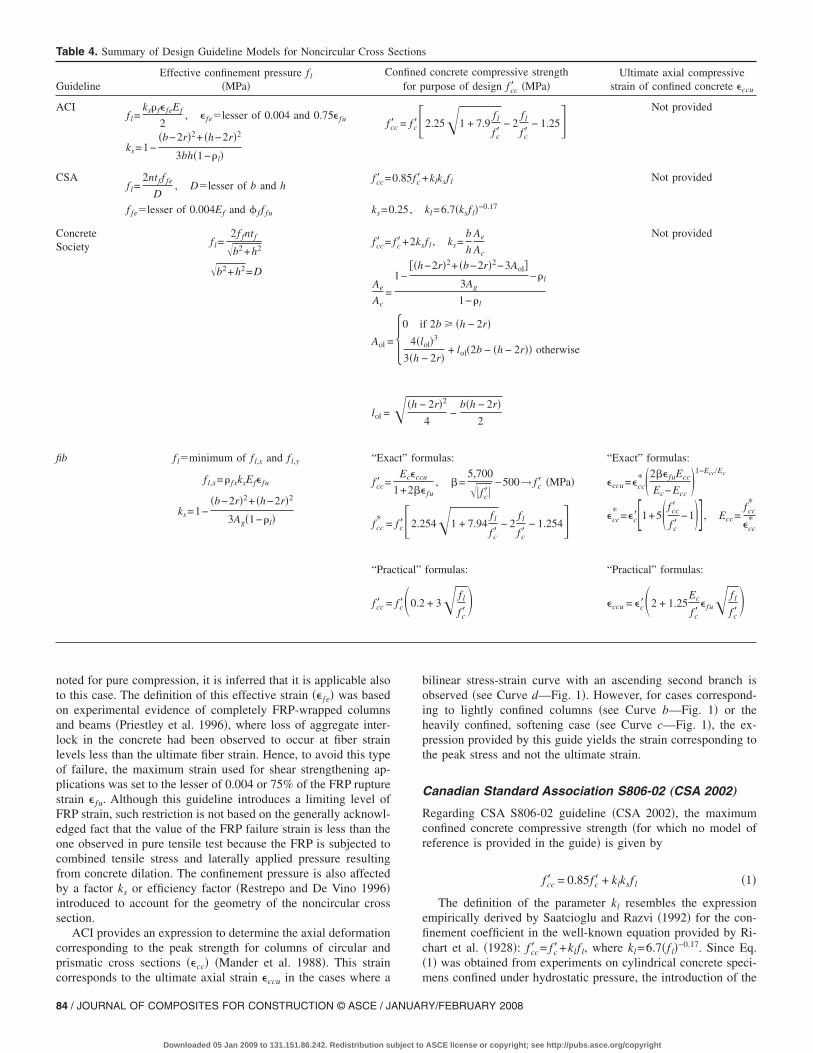
noted for pure compression, it is inferred that it is applicable alsoto this case. The definition of this effective strain �� fe� was basedon experimental evidence of completely FRP-wrapped columnsand beams �Priestley et al. 1996�, where loss of aggregate inter-lock in the concrete had been observed to occur at fiber strainlevels less than the ultimate fiber strain. Hence, to avoid this typeof failure, the maximum strain used for shear strengthening ap-plications was set to the lesser of 0.004 or 75% of the FRP rupturestrain � fu. Although this guideline introduces a limiting level ofFRP strain, such restriction is not based on the generally acknowl-edged fact that the value of the FRP failure strain is less than theone observed in pure tensile test because the FRP is subjected tocombined tensile stress and laterally applied pressure resultingfrom concrete dilation. The confinement pressure is also affectedby a factor ks or efficiency factor �Restrepo and De Vino 1996�introduced to account for the geometry of the noncircular crosssection.
ACI provides an expression to determine the axial deformationcorresponding to the peak strength for columns of circular andprismatic cross sections ��cc� �Mander et al. 1988�. This strain
Table 4. Summary of Design Guideline Models for Noncircular Cross S
GuidelineEffective confinement pressure f l
�MPa�C
ACIf l=
ks� f� feEf
2, � fe�lesser of 0.004 and 0.75� fu fc�
ks=1−�b−2r�2+ �h−2r�2
3bh�1−�l�
CSAf l=
2ntf f fe
D, D�lesser of b and h
fcc� =
f fe�lesser of 0.004Ef and � f f fu ks=0
ConcreteSociety f l=
2f fntf
�b2+h2
�b2+h2=D
fcc� =
Ae
Ac=
Aol =
lol =
fib fl�minimum of f l,x and f l,y
f l,x=� fxksEf� fu
ks=1−�b−2r�2+ �h−2r�2
3Ag�1−�l�
“Exa
fcc� =
fcc* =
“Pra
fcc� =
corresponds to the ultimate axial strain �ccu in the cases where a
84 / JOURNAL OF COMPOSITES FOR CONSTRUCTION © ASCE / JANUAR
Downloaded 05 Jan 2009 to 131.151.86.242. Redistribution subject to
bilinear stress-strain curve with an ascending second branch isobserved �see Curve d—Fig. 1�. However, for cases correspond-ing to lightly confined columns �see Curve b—Fig. 1� or theheavily confined, softening case �see Curve c—Fig. 1�, the ex-pression provided by this guide yields the strain corresponding tothe peak stress and not the ultimate strain.
Canadian Standard Association S806-02 „CSA 2002…
Regarding CSA S806-02 guideline �CSA 2002�, the maximumconfined concrete compressive strength �for which no model ofreference is provided in the guide� is given by
fcc� = 0.85fc� + klksf l �1�
The definition of the parameter kl resembles the expressionempirically derived by Saatcioglu and Razvi �1992� for the con-finement coefficient in the well-known equation provided by Ri-chart et al. �1928�: fcc� = fc�+klf l, where kl=6.7�f l�−0.17. Since Eq.�1� was obtained from experiments on cylindrical concrete speci-
s
concrete compressive strengthurpose of design fcc� �MPa�
Ultimate axial compressivestrain of confined concrete �ccu
2.25�1 + 7.9f l
fc�− 2
f l
fc�− 1.25� Not provided
+klksf l Not provided
kl=6.7�ksf l�−0.17
f l , ks=b
h
Ae
Ac
Not provided
−2r�2+ �b−2r�2−3Aol�
3Ag−�l
1−�l
f 2b �h − 2r�
ol�3
2r�+ lol�2b − �h − 2r�� otherwise
2r�2
4−
b�h − 2r�2
mulas: “Exact” formulas:
u
fu, =
5,700
��fc��−500→ fc� �MPa� �ccu=�cc
* �2� fuEcc
Ec−Ecc�1−Ecc/Ec
54�1 + 7.94f l
fc�− 2
f l
fc�− 1.254� �cc
* =�c��1+5� fcc�
fc�−1�� , Ecc=
fcc*
�cc*
formulas: “Practical” formulas:
+ 3� f l
fc� �ccu = �c�2 + 1.25
Ec
fc�� fu� f l
fc�
ection
onfinedfor p
c = fc��0.85fc�
.25,
fc�+2ks
1−��h
�0 i
4�l3�h −
��h −
ct” for
Ec�cc
1+2�
fc��2.2
ctical”
fc�0.2
mens confined under hydrostatic pressure, the introduction of the
Y/FEBRUARY 2008
ASCE license or copyright; see http://pubs.asce.org/copyright

shape factor ks in this guideline is intended to account for thedifferent shape of the cross section. In fact, ks=1.0 and 0.25 forcircular and noncircular cross sections, respectively. The confine-ment pressure f l, in the case of noncircular cross sections, is com-puted based on the formula derived from the equilibrium of forcesdeveloped in a circular cross section under confinement action,where the diameter D corresponds to the minimum side dimen-sion of the noncircular cross section �CSA 1994�. The maximumstress that the FRP jacket can attain at failure �f fe� is based on thesame strain limitation given by ACI. No expression for the calcu-lation of the ultimate axial strain for confined concrete is providedin the guide.
Concrete Society Technical Report No. 55 2004
For columns of circular cross sections, the Concrete Society pro-poses a design-oriented model, developed by Lam and Teng�2003a�. This model was calibrated against all the experimentaldata available at the time. As shown in Fig. 2, the confined con-crete model is basically composed of an initial parabolic branchfollowed by an ascending linear branch with a smooth transitionat the strain value �t. The model is only applicable for monotoni-cally increasing values of confined compressive strength �no soft-ening or descending second branch�; therefore, a criterion ofminimum confinement �Xiao and Wu 2000� is established and isgiven as follows:
2ntfEf
D�fc��2 � 0.183 �mm2/N� �2�
The value of the confined concrete compressive strength fcc� isgiven by Eq. �3�, which was shown to yield good agreement withtests conducted on both CFRP-wrapped specimens and concrete-filled FRP Tubes �CFFT�, although experimentally based on thelatter �Lillistone 2000�. Note that in Eq. �3� fcc� is based on thecharacteristic unconfined cube strength fcu
* , and it differs from theone actually recommended by the model of Lam and Teng�2003a�
fcc� = fcu* + 0.052ntf
DEf �3�
With regards to the ultimate axial strain of the confined con-crete �ccu, the expression provided in this guideline was the oneproposed by Lam and Teng �2003a� in their original model �seeTable 3�. This expression implies the dependence of the ultimateaxial deformation on the stiffness provided by the FRP jacket andcontemplates nonlinearity determined through trends from testdata �same database used for calibration of model�. The nonlin-earity coefficients reflect the fact that the secant Poisson’s ratio of
Fig. 2. Lam and Teng’s stress strain model for FRP-confined con-crete circular columns �FRP Strengthened RC Structures, Teng et al.�2002�. Copyright John Wiley & Sons Limited. Reproduced withpermission.�
FRP-confined concrete ultimately depends strongly on the con-
JOURNAL OF COMPOSITE
Downloaded 05 Jan 2009 to 131.151.86.242. Redistribution subject to
finement stiffness ratio: 2Efntf /EsecD. Additionally, the suggestedequation for the ultimate strain includes a strain efficiency factor�0.6� proposed by the authors of the model, and again, calibratedexperimentally. The guideline recommends that if the ultimateaxial strain �ccu were to be greater than 0.01, then the designfailure stress should be taken as the value corresponding to �ccu
equal to 0.01 from the stress-strain curve �see Table 3�.The expression to predict the compressive strength of FRP-
confined concrete in members of noncircular cross sections wasbased on an equation originally developed for circular cross sec-tions: fcc� = fc�+klksf l, where kl was derived empirically and con-servatively taken as 2.0. Additionally, ks represents the effectiveconfinement area ratio �Ae /Ac� divided by the side aspect ratio�h /b�. The confinement pressure f l is given in terms of theequivalent diameter D, which is defined by Teng et al. �2002� asthe diagonal distance of the cross section �see Fig. 3�. The modelwas originally proposed by Teng et al. �2002� and calibratedagainst a database composed of plain concrete specimens of mini-mum and maximum cross-sectional dimensions of 150�150 mm �6�6 in.� and 150�225 mm �6�9 in.�, respectively,and side-aspect-ratios of 1.0, 1.3, and 1.5. Whereas this modelconsiders the generally accepted approach of an effectively con-fined area defined by four second-degree parabolas with initialslopes of diagonal lines between the column corners, the ConcreteSociety recommends a simpler assumption of the initial slopesstarting at 45° to the face of the column. The concept of an inef-fectively confined area when the parabolas overlap �for side-aspect-ratios h /b greater than the value of 2.0� is introduced inthe calculation of the effectively confined area of concrete �Ae��see Fig. 3�. This feature was adopted from the model proposedby Maalej et al. �2003�.
For the case of FRP-confined concrete members of noncircularcross sections, no provision is given for the calculation of theultimate axial strain �ccu.
Technical Report by the Fédération internationale duBéton „fib Bulletin 14 … 2001
The design recommendations provided by fib for columns of cir-cular and noncircular cross sections are based on the model pro-posed by Spoelstra and Monti �1999�. These authors developed aniterative analysis-oriented model for circular columns from whichtwo sets of closed-form equations for maximum confined con-crete compressive strength fcc� and ultimate axial strain �ccu werederived: “Exact” and “approximate” formulas. The former re-quires the prior calculation of the parameters fcc
* and �cc* of the
Mander stress-strain curve, and the secant modulus of elasticity atultimate Esec,u �Eq. �4��. The latter are alternative expressions ob-tained by Spoelstra and Monti �1999� based on regression analy-sis of the proposed model results, and they only require the priorcalculation of the confinement pressure f l. These formulas aremore readily used for design purposes. This analysis was based
Fig. 3. Overlapping parabolas in confined region �Concrete Society2004, with permission�
on the assumptions of �c� of 0.2% and a variation of Ec of 20%
S FOR CONSTRUCTION © ASCE / JANUARY/FEBRUARY 2008 / 85
ASCE license or copyright; see http://pubs.asce.org/copyright

with respect to the reference value of 5,700�fc� for a range of fc�=30–50 MPa �4.4–7.3 ksi�. Note that in both sets of formulas,the value of � fu �Tables 3 and 4� should be taken as f fu /Ef,
Esec,u =Ec
1 + 2� fu⇒ fcc� = Esec,u�ccu =
Ec�ccu
1 + 2� fu�4�
A particular feature of the model presented by Spoelstra andMonti �1999� is the inclusion of a parameter to account for thephysical degradation of concrete when subjected to loading �Eq.�5��. This parameter was originally developed by Pantazopoulouand Mills �1995� in a constitutive model for unconfined concreteunder uniaxial compressive loading and was first obtained interms of physical properties �e.g., the volumetric fraction of pasteper unit volume of concrete and the water-cement ratio�. How-ever, the parameter was adapted by Spoelstra and Monti to de-pend on more commonly available mechanical properties, such asfc�, �c�, and Ec:
=5,700
��fc��− 500 �fc� in MPa� �5�
In addition, fib highlights that the hoop failure strain of theFRP jacket, based on experimental evidence, is lower than theultimate strain obtained by tensile testing of the material. Theguideline points out that this reduction is due to several reasons,
Table 5. Specimens Characteristics
SpecimenD
�mm�b
�mm�h
�mm�h
b
H�m� �c
C1 508 NA NA NA 1.12 2
C2
S1 NA 458 458 1.0 1.02 2
S2
R1 NA 318 635 2.0 1.37 2
R22 2
Fig. 4. Confining pressure effect due to Partial-Wrapping �fib Bulle-tin 14, with permission of the fédération internationale du béton�
Note: 1 in.=25.4 mm; 1in. =6.45 cm ; 1 ksi=6.9 MPa.
86 / JOURNAL OF COMPOSITES FOR CONSTRUCTION © ASCE / JANUAR
Downloaded 05 Jan 2009 to 131.151.86.242. Redistribution subject to
such as the quality of execution �fibers not perfectly aligned orsurface preparation not appropriate�, the size effect when apply-ing several layers, the effect of wrapping the material on thecorners of low radius, and the combined state of stress of the FRPwrapping. Because of the lack of data on these effects, no appro-priate reduction factors are suggested at the present time.
In the case of columns of circular cross sections, for the cal-culation of the effective confinement pressure exerted by the FRPjacket �f l�, fib provides a confinement effectiveness coefficient ke
less than 1.0 for a confinement by partial wrapping and equal to1.0 for a confinement by full wrapping �See Fig. 4 and Eq. �6���Mander et al. 1988�. In the case of noncircular columns, a pa-rameter ks still introduces the confinement effectiveness but in ageometrical way �Eq. �7��. The guideline does not include provi-sions for the consideration of an additional factor that accountsfor the effect of partial wrapping in noncircular specimens,
ke = 1 −s�
2D2
�6�
ks = 1 −�b − 2r�2 + �h − 2r�2
3Ag�1 − �l��7�
Comparative Study of Guidelines PredictiveEquations
To evaluate the performance and contrast the different approachestaken by the guidelines for the determination of the compressivestrength �fcc� � and the ultimate axial compressive strain for con-fined concrete ��ccu�, a total of six RC column specimens �threestrengthened specimens with their corresponding control units� ofdifferent cross-sectional shapes �circular, square, and rectangular�and equal gross areas �Ag� were selected, designed, constructed,and tested. These specimens were part of a research study on thesize effect of FRP-confined RC columns recently conducted�Rocca et al. 2006�. This assessment is not intended to be com-prehensive, but the three relevant cases presented here indicatethe trends of the guidelines under study.
Table 5 shows the characteristics of each of the specimensselected. The first column shows the specimen acronym, wherethe letter in each label indicates the shape of the cross section:C�circular; S�square; and R�rectangular. The following param-eters are presented in Table 5 in the same order: The cross-sectional dimensions �diameter of the circular cross section D andsides b and h of the noncircular cross sections�, side-aspect-ratioh /b, total column height H, gross cross-sectional area Ag, longi-
�l
�%�fy
�MPa�fc�
�MPa�� f
�%�
fco��MPa�
� fcc�
fco� ��cu
�mm/mm�
��ccu
�cu�
1.53 446 31.7 0.00 26.3 0.003
446 31.9 0.26 �1.44� �4.48�
1.48 446 32.1 0.00 26.0 0.002
446 32.1 0.29 �1.06� �1.67�
1.56 447 30.1 0.00 24.7 0.002
447 30.4 0.32 �1.01� �3.34�
Ag
m2�
0.3
1.0
0.2
Y/FEBRUARY 2008
ASCE license or copyright; see http://pubs.asce.org/copyright
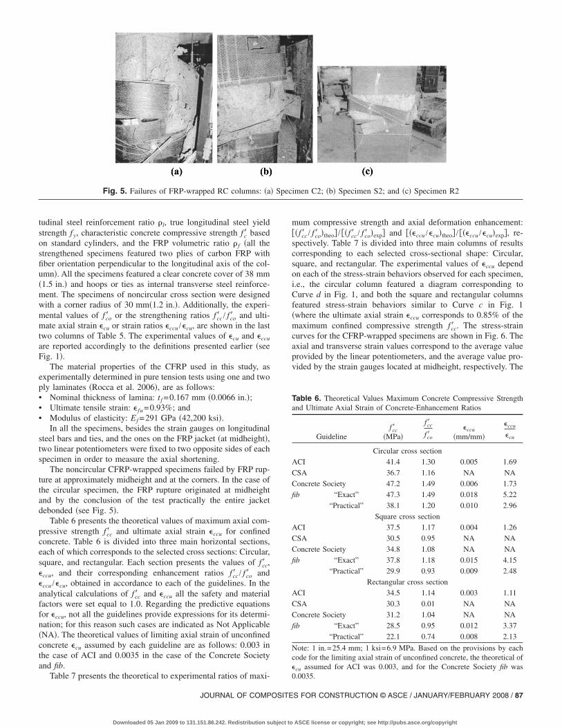
tudinal steel reinforcement ratio �l, true longitudinal steel yieldstrength fy, characteristic concrete compressive strength fc� basedon standard cylinders, and the FRP volumetric ratio � f �all thestrengthened specimens featured two plies of carbon FRP withfiber orientation perpendicular to the longitudinal axis of the col-umn�. All the specimens featured a clear concrete cover of 38 mm�1.5 in.� and hoops or ties as internal transverse steel reinforce-ment. The specimens of noncircular cross section were designedwith a corner radius of 30 mm�1.2 in.�. Additionally, the experi-mental values of fco� or the strengthening ratios fcc� / fco� and ulti-mate axial strain �cu or strain ratios �ccu /�cu, are shown in the lasttwo columns of Table 5. The experimental values of �cu and �ccu
are reported accordingly to the definitions presented earlier �seeFig. 1�.
The material properties of the CFRP used in this study, asexperimentally determined in pure tension tests using one and twoply laminates �Rocca et al. 2006�, are as follows:• Nominal thickness of lamina: tf =0.167 mm �0.0066 in.�;• Ultimate tensile strain: � fu=0.93%; and• Modulus of elasticity: Ef =291 GPa �42,200 ksi�.
In all the specimens, besides the strain gauges on longitudinalsteel bars and ties, and the ones on the FRP jacket �at midheight�,two linear potentiometers were fixed to two opposite sides of eachspecimen in order to measure the axial shortening.
The noncircular CFRP-wrapped specimens failed by FRP rup-ture at approximately midheight and at the corners. In the case ofthe circular specimen, the FRP rupture originated at midheightand by the conclusion of the test practically the entire jacketdebonded �see Fig. 5�.
Table 6 presents the theoretical values of maximum axial com-pressive strength fcc� and ultimate axial strain �ccu for confinedconcrete. Table 6 is divided into three main horizontal sections,each of which corresponds to the selected cross sections: Circular,square, and rectangular. Each section presents the values of fcc� ,�ccu, and their corresponding enhancement ratios fcc� / fco� and�ccu /�cu, obtained in accordance to each of the guidelines. In theanalytical calculations of fcc� and �ccu all the safety and materialfactors were set equal to 1.0. Regarding the predictive equationsfor �ccu, not all the guidelines provide expressions for its determi-nation; for this reason such cases are indicated as Not Applicable�NA�. The theoretical values of limiting axial strain of unconfinedconcrete �cu assumed by each guideline are as follows: 0.003 inthe case of ACI and 0.0035 in the case of the Concrete Societyand fib.
Fig. 5. Failures of FRP-wrapped RC columns: �a
Table 7 presents the theoretical to experimental ratios of maxi-
JOURNAL OF COMPOSITE
Downloaded 05 Jan 2009 to 131.151.86.242. Redistribution subject to
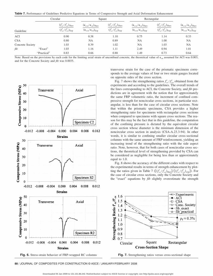
mum compressive strength and axial deformation enhancement:��fcc� / fco� �theo� / ��fcc� / fco� �exp� and ���ccu /�cu�theo� / ���ccu /�cu�exp�, re-spectively. Table 7 is divided into three main columns of resultscorresponding to each selected cross-sectional shape: Circular,square, and rectangular. The experimental values of �ccu dependon each of the stress-strain behaviors observed for each specimen,i.e., the circular column featured a diagram corresponding toCurve d in Fig. 1, and both the square and rectangular columnsfeatured stress-strain behaviors similar to Curve c in Fig. 1�where the ultimate axial strain �ccu corresponds to 0.85% of themaximum confined compressive strength fcc� . The stress-straincurves for the CFRP-wrapped specimens are shown in Fig. 6. Theaxial and transverse strain values correspond to the average valueprovided by the linear potentiometers, and the average value pro-vided by the strain gauges located at midheight, respectively. The
Table 6. Theoretical Values Maximum Concrete Compressive Strengthand Ultimate Axial Strain of Concrete-Enhancement Ratios
Guidelinefcc�
�MPa�
fcc�
fco��ccu
�mm/mm�
�ccu
�cu
Circular cross section
ACI 41.4 1.30 0.005 1.69
CSA 36.7 1.16 NA NA
Concrete Society 47.2 1.49 0.006 1.73
fib “Exact” 47.3 1.49 0.018 5.22
“Practical” 38.1 1.20 0.010 2.96
Square cross section
ACI 37.5 1.17 0.004 1.26
CSA 30.5 0.95 NA NA
Concrete Society 34.8 1.08 NA NA
fib “Exact” 37.8 1.18 0.015 4.15
“Practical” 29.9 0.93 0.009 2.48
Rectangular cross section
ACI 34.5 1.14 0.003 1.11
CSA 30.3 0.01 NA NA
Concrete Society 31.2 1.04 NA NA
fib “Exact” 28.5 0.95 0.012 3.37
“Practical” 22.1 0.74 0.008 2.13
Note: 1 in.=25.4 mm; 1 ksi=6.9 MPa. Based on the provisions by eachcode for the limiting axial strain of unconfined concrete, the theoretical of�cu assumed for ACI was 0.003, and for the Concrete Society fib was
imen C2; �b� Specimen S2; and �c� Specimen R2
� Spec0.0035.
S FOR CONSTRUCTION © ASCE / JANUARY/FEBRUARY 2008 / 87
ASCE license or copyright; see http://pubs.asce.org/copyright
and for the Concrete Society and fib was 0.0035.
88 / JOURNAL OF COMPOSITES FOR CONSTRUCTION © ASCE / JANUAR
Downloaded 05 Jan 2009 to 131.151.86.242. Redistribution subject to
transverse strain for the case of the prismatic specimens corre-sponds to the average values of four or two strain gauges locatedon opposite sides of the cross section.
Fig. 7 shows the strengthening ratios fcc� / fco� obtained from theexperiments and according to the guidelines. The overall trends ofthe lines corresponding to ACI, the Concrete Society, and fib pre-dictions are in agreement with the notion that for approximatelythe same FRP volumetric ratio, the increment of confined com-pressive strength for noncircular cross sections, in particular rect-angular, is less than for the case of circular cross sections. Notethat within the prismatic specimens, CSA provides a higherstrengthening ratio for specimens with rectangular cross sectionswhen compared to specimens with square cross sections. The rea-son for this may be the fact that in this guideline, the computationof the confining pressure is dictated by the equivalent circularcross section whose diameter is the minimum dimension of thenoncircular cross section in analysis �CSA-A.23.3-94�. In otherwords, it is similar to confining smaller circular cross-sectionalcolumns with the same amount of FRP reinforcement, yielding anincreasing trend of the strengthening ratio with the side aspectratio. Note, however, that for both cases of noncircular cross sec-tions, the theoretical level of strengthening provided by CSA canbe considered as negligible for being less than or approximatelyequal to 1.0.
Fig. 8 shows the accuracy of the different codes with respect tothe experimental results in terms of strength enhancement by plot-ting the ratios given in Table 7 ���fcc� / fco� �theo� / ��fcc� / fco� �exp��. Forthe case of circular cross sections, only the Concrete Society andthe “exact” equations by fib slightly overestimate the strength
sive Strength and Axial Deformation Enhancement
Rectangular
c / fco� �Theo
cc� / fco� �Exp
��ccu /�cu�Theo
��ccu /�cu�Exp
�fcc� / fco� �Theo
�fcc� / fco� �Exp
��ccu /�cu�Theo
��ccu /�cu�Exp
1.10 0.75 1.14 0.33
0.89 NA 1.00 NA
1.02 NA 1.03 NA
1.11 2.49 0.94 1.01
0.88 1.49 0.73 0.64
nfined concrete, the theoretical value of �cu assumed for ACI was 0.003,
Fig. 7. Strengthening ratios versus cross-sectional shape
Table 7. Performance of Guidelines Predictive Equations in Terms of Compres
Circular Square
Guideline
�fcc� / fco� �Theo
�fcc� / fco� �Exp
��ccu /�cu�Theo
��ccu /�cu�Exp
�fc�
�f
ACI 0.90 0.38
CSA 0.80 NA
Concrete Society 1.03 0.39
fib “Exact” 1.03 1.16
“Practical” 0.83 0.66
Note: Based on the provisions by each code for the limiting axial strain of unco
Fig. 6. Stress-strain behavior of FRP-wrapped RC columns
Y/FEBRUARY 2008
ASCE license or copyright; see http://pubs.asce.org/copyright

enhancement �approximately, 3%�. Regarding the noncircularcross sections, only ACI and the Concrete Society overestimatethe strength increase for both square and rectangular cross sec-tions. The “exact” formulas by fib overestimate the strength en-hancement for only the square type of cross section.
Fig. 9 shows the accuracy of the guidelines in predicting theultimate axial strain enhancement �ccu /�cu. A theoretical value of�cu=0.003 was used in the case of ACI, and a value of 0.0035 wasused in the cases of the Concrete Society and fib. Recall that CSAdoes not provide expressions for the calculation of �ccu. The esti-mations vary within a range of approximately ±50% of the ex-perimental ratios, with the exception of the value correspondingto the “exact” equations from fib for the case of square columns�about 250%�. As the ultimate axial strain of concrete is a func-tion of different parameters �size and type of aggregates; mixproportions; water/cement ratio; and in the case of confined con-crete, greatly influenced by the stiffness of the jacket material �DeLorenzis and Tepfers 2001�, the accurate analytical representationof �ccu for design purposes is a challenge. This particular chal-lenge is based on the difficulty posed by the inclusion of theinfluencing parameters, and in particular, the interaction of con-crete dilation with confining FRP.
Table 8 presents the theoretical to experimental ratios of load-carrying capacity of the FRP-strengthened RC columns
Fig. 8. Guidelines performance—ratio of theoretical concrete com-pressive strength enhancement to experimental
Fig. 9. Guidelines performance—ratio of theoretical ultimate axialdeformation enhancement to experimental
JOURNAL OF COMPOSITE
Downloaded 05 Jan 2009 to 131.151.86.242. Redistribution subject to
�Ptheo / Pexp�. The theoretical or design values of axial resistancewere computed considering the material safety factors and/or thestrength reduction factors as required by each guideline �see Table1�. Additionally, a value of 0.95 was assigned for the parameterCE �CFRP applications and interior exposure� in ACI, and a valueof 1.2 was assigned for � f �good quality control on applicationconditions and application process� in fib. The results presented inTable 8 are plotted in Fig. 10. All the predictions appear to beconservative. The results mainly vary in a range from about 60 to95% of the experimentally obtained load-carrying capacity, withthe exception of the ratios corresponding to CSA that show aminimum percentage of about 40, which can be considered as tooconservative.
Discussion
The limits presented in Table 2, which primarily dealt with thedimensions of the specimens’ cross sections, side aspect ratios�h /b�, and loading types �concentric�, are the results of the lim-ited experimental evidence on the area of FRP-confinement ofreal-size RC columns. Additionally, these limits have not allowedthe appropriate implementation of key effects in the current mod-els. These effects have been identified as follows:• The instability of longitudinal steel reinforcement;• The concrete dilation dependent on the pseudo-Poisson’s ratio;• The contribution of the internal transverse steel reinforcement
to the confinement; and• An appropriate reduction factor to account for the premature
failure of the FRP jacket. Only the model presented by theConcrete Society introduces this parameter in the predictingequations. Two reasons may be the cause of this phenomenon;namely, the triaxial state of stress to which the FRP wrap is
Table 8. Performance of Guidelines Predictive Equations—Ratio ofDesign Load Capacity Experimental Ptheo / Pexp
Circular Square Rectangular
ACI 0.61 0.70 0.71
CSA 0.52 0.57 0.40
Concrete Society 0.87 0.75 0.76
fib “Exact” 0.86 0.95 0.85
“Practical” 0.70 0.74 0.65
Fig. 10. Guidelines Performance—ratio of design axial load capacityto experimental
S FOR CONSTRUCTION © ASCE / JANUARY/FEBRUARY 2008 / 89
ASCE license or copyright; see http://pubs.asce.org/copyright

subjected as opposed to the pure axial state of coupons undermaterial characterization �hoop stress in addition to the pres-sure laterally applied as a result of the concrete dilation� andthe creation of stress concentration regions along the wrapproduct of the cracking of the concrete as it dilates.Regarding the maximum confined concrete compressive
strength fcc� , the models presented by ACI and fib, which are bothbased on the Mander formula for steel-confined concrete, yielddifferent results because of the selection of different expressionsfor key parameters. In the case of ACI, the maximum confinedcompressive strength fcc� is directly computed from the peakstrength given by the Mander formula. However, the predictiveequations from fib are developed based on two other relationships“merged” in the model by Spoelstra and Monti �1999�: Popovics,a concrete stress-strain curve under a constant confining action,and the one developed by Pantazopoulou and Mills �1995� for thedilation characteristics of concrete, allowing one to establish arelationship between the axial and the transverse strain �Monti2001�. The design approaches presented by CSA and the ConcreteSociety belong to the empirical or analytical type, and the valuesgiven to their parameters were based on plain concrete specimens.
Regarding the determination of the confining pressure in acolumn of noncircular cross section, all the guidelines exceptCSA consider the effect of the cross-sectional geometry by theinclusion of a confinement effectiveness coefficient �ks�, which isexpressed as a function of the side dimensions �b ,h�, corner ra-dius �r�, and the ratio of the area of longitudinal steel reinforce-ment to the cross-sectional area of the column ��l�. CSA dictatesa constant value of 0.25 in addition to an equivalent diametertaken as the minimum side dimension of a noncircular crosssection.
With respect to the consideration of a “strain efficiency factor”accounting for the premature failure of the FRP jacket, ACI andCSA limit the level of hoop strain in the FRP to be attained atfailure �� fe� by taking the minimum value of either 0.004 or0.75� fu. However, this limitation is not based on FRP perfor-mance considerations. The Concrete Society includes a limitingvalue of strain �� fe� corresponding to 60% of �� fu� �based onexperimental evidence�. fib does not recommend a reduction fac-tor at the present time.
The internal damage �cracking� of concrete under loading isonly introduced in the models adopted by the Concrete Societyand fib. In the former, the concrete deterioration is represented byexperimentally fitted coefficients in the expression for the calcu-lation of �ccu �Lam and Teng 2003a�. In the latter, the damage isbased on a constitutive model for unconfined concrete underuniaxial compression proposed by Pantazopoulou and Mills�1995�, whose equations are rearranged to yield a relationshipbetween lateral and axial strain. None of the presented guide-lines introduces the effect of longitudinal steel reinforcementinstability.
With respect to the accuracy of the predictive equations, CSAwas the only guide providing a strengthening ratio for a columnof rectangular cross section higher than the ratio corresponding toa square column, which is contrary to the intuitive notion that forincrements of the side aspect ratio �h /b�, the resulting fcc� de-creases at an equal FRP volumetric ratio. However, the predictivevalues for both noncircular columns tested in this program werenot larger than 1.0, a value associated with no strengthening.
The theoretical to experimental strength enhancement ratiosfor circular and noncircular cross sections ���fcc� / fco� �theo� /��fcc� / fco� �exp�� were best approximated by the predictive equations
provided by the Concrete Society.90 / JOURNAL OF COMPOSITES FOR CONSTRUCTION © ASCE / JANUAR
Downloaded 05 Jan 2009 to 131.151.86.242. Redistribution subject to
Regarding the prediction of the axial strain enhancement, onlyACI and fib provide equations for circular and noncircular col-umns. The Concrete Society provides an equation solely for thecase of circular columns. In general, the scatter of the predictionsfor strain enhancement was much larger than for strength en-hancement. In fact, the “exact” equations by fib appear to overes-timate the strain enhancement for the case of square columns byabout 250%. This overestimation may be partly because of thedifficulty in accurately representing the effects of parameters suchas size and type of aggregates; mix proportions; water/cementratio; and, in the case of confined concrete, the stiffness of theFRP jacket.
The design axial capacities of the strengthened RC columnswere compared to the values experimentally obtained. Accountingfor the guide-specific reduction and material factors, the designpredictions from all guidelines were conservative, with the high-est level provided by CSA and the lowest by the “exact” formu-lation from fib.
Conclusions
Design approaches for FRP confinement of RC columns fromfour international design guidelines were presented, reviewed,and compared. Limits and design equations for the calculation ofthe maximum axial compressive strength fcc� and ultimate axialstrain �ccu of FRP-confined RC members for circular and noncir-cular cross-sectional shapes were outlined. The experimentalresults from six RC columns of different cross-sectional shapes�circular, square, and rectangular� were contrasted to theoreticalpredictions obtained in accordance to each guideline.
For the purpose of an appropriate comparison of axial defor-mation enhancement, it is necessary to set a stress value at whichthe measurement is made, particularly for the case of stress-straincurves with a descending second branch �see Curves b and cin Fig. 1�. For this, an arbitrary value of 0.85fcc� was adopted�Hognestad 1951�.
Given the present knowledge and experimental evidence, theresearch community should consider further experimental andanalytical work allowing one to confirm the basic assumptions,and providing relevant and substantial data information to feedand correctly calibrate numerical and analytical models. Althougha vast experimental campaign on real-size RC columns followingthe conventional testing methodology is a choice, the currentavailable sensing technology used in a few dimensionally relevantspecimens represents an innovative alternative testing protocol,allowing one to obtain accurate information, and most important,allowing the understanding of the physical phenomena. The mea-surements should be targeted to the strain distribution along theperimeter of the FRP jacket, the strain distribution of the longitu-dinal and transverse steel reinforcement, the lateral �outward� de-formation of the longitudinal steel bars product of the concretelateral dilation �bar instability�, the concrete dilation, and crackpropagation detection. A more meaningful interpretation of theexperimental data currently available in the literature would be-come possible once performance phenomena and controlling pa-rameters are fully understood.
Acknowledgments
The writers would like to acknowledge the funding and support
received from: National Science Foundation �supplement GrantY/FEBRUARY 2008
ASCE license or copyright; see http://pubs.asce.org/copyright
No. 0453808�, MAPEI S.p.A. in Milan �Italy�, NSF Industry/University Cooperative Research Center on Repair of Buildingsand Bridges with Composites �RB2C�, and the University Trans-portation Center on Advanced Materials and NDT Technologiesbased at the University of Missouri-Rolla �UMR�.
Notation
The following symbols are used in this paper:Ac � cross-sectional area of concrete in column
�Concrete Society��Ag�1−�l�;Ae � effectively confined area
�Ag− ��h−2r�2+ �b−2r�2� /3−�lAg;Ag � total cross-sectional area�bh �Only for Concrete
Society�bh− �4− �r2�;Aol � area of overlap of the parabolas in a prismatic
cross section with side aspect ratio greater than2.0 �Concrete Society��0 if 2b� �h−2r�,4�lol�3 /3�h−2r�+ lol�2b− �h−2r�� otherwise;
As � area of steel reinforcement�Ag�l;b � short side dimension of a noncircular cross
section;bf � width of FRP strip in partial wrapping;
CE � environmental reduction factor �ACI�;D � diameter of circular cross section, least lateral
dimension of the prismatic cross section �CSA�,diameter of equivalent circular column�Concrete Society���b2+h2;
Ec � initial modulus of elasticity of concrete;Ef � tensile modulus of elasticity of FRP;
Esec � secant modulus of concrete �Concrete Society��fc� /�c�;
Esec,u � secant modulus of elasticity of concrete atultimate �fib��Esec,u=Ec / �1+2� fu�;
E2 � slope of linear portion of confined stress-straincurve �Concrete Society���fcc� − fc�� /�ccu;
fc� � characteristic concrete compressive strengthdetermined from standard cylinder;
fcc� � compressive strength of confined concrete �Forexperiments: Peak load minus the contributionsteel and divided by the cross-sectional concretearea�;
fco� � compressive strength of unconfined concrete �Forexperiments: Peak load minus the contributionsteel and divided by the cross-sectional concretearea�;
fcu* � characteristic concrete compressive strength
determined from cube�fc� /0.8;f fu � ultimate tensile strength of FRP;f l � confinement pressure due to FRP jacket;fy � yield strength of longitudinal steel reinforcement;H � height of column;h � long side dimension of a noncircular cross
section;kl � confinement parameter �CSA��6.7�ksf l�−0.17;ke � confinement effectiveness coefficient accounting
for effect of partial wrapping in columns ofcircular cross sections �fib�= �1−s� /2D�2;
ks � confinement effectiveness coefficient accountingfor the geometry of cross sections�1 for circular
�ACI, CSA�, 0.25 for noncircular �CSA�,JOURNAL OF COMPOSITE
Downloaded 05 Jan 2009 to 131.151.86.242. Redistribution subject to
1− ��b−2r�2+ �h−2r�2� /3Ag�1−�l�, for noncircular�ACI, fib�, �b /h��1− ��b−2r�2+ �h−2r�2
−3Aol� /3Ag−�l / �1−�l� for noncircular �ConcreteSociety�;
lol � length of overlapping region �Concrete Society����h−2r�2 /4−b�h−2r� /2;
n � number of FRP plies composing the jacket;Pexp � experimental axial load carrying capacity of
FRP-confined RC column;Ptheo � design axial load carrying capacity of
FRP-confined RC column;r � corner radius of noncircular cross sections;s � pitch in partial wrapping;
s� � clear spacing between FRP wraps;tf � FRP nominal ply thickness; � concrete parameter �fib�=5,700 /��fc��−500;
�c � partial safety factor for concrete �CSA, ConcreteSociety fib�;
�� � partial safety factor for strain of FRP �ConcreteSociety�;
�E � partial safety factor for modulus of elasticity ofFRP �Concrete Society�;
� f � material safety factor for FRP �CSA, fib�;�mm � additional partial safety factor for manufacture of
FRP �Concrete Society�;�s � partial safety factor for steel �CSA, Concrete
Society, fib�;�c� � axial compressive strain corresponding to fc�;
�ccu � ultimate axial compressive strain of confinedconcrete;
�cu � ultimate axial compressive strain of unconfinedconcrete�0.003 for �ACI�, 0.0035 for �ConcreteSociety, fib�;
� fe � FRP effective strain �strain level reached atfailure�;
� fu � ultimate tensile strain of the FRP;�t � Position of transition region between parabola
and straight line �Concrete Society��2fc� / �Ec−E2�;
� f � volumetric ratio of FRP reinforcement
=��4ntf/D��bf/s� for circular
2ntf�b + h�/bh for Noncircular�;
�l � ratio of the area of longitudinal steelreinforcement to the cross-sectional area of acompression member�As /Ag;
� � strength reduction factor �ACI�; and� f � additional FRP strength reduction factor �ACI�.
References
American Concrete Institute �ACI�. �1999�. “Building code requirementsfor structural concrete.” ACI 318-99, Farmington Hills, Mich.
American Concrete Institute �ACI�. �2002�. “Guide for the design andconstruction of externally bonded FRP systems for strengthening ofconcrete structures.” ACI 440.2R-02, Farmington Hills, Mich.
Canadian Standards Association �CSA�. �1994�. “Design of concretestructures.” CSA A.23.3, Rexdale, Ont., Canada.
Canadian Standards Association �CSA�. �2002�. “Design and constructionof building components with fibre-reinforced polymers.” CSA-S806,Rexdale, Ont., Canada.
Carey, S., and Harries, K. �2003�. “The effects of shape, gap, and scale on
S FOR CONSTRUCTION © ASCE / JANUARY/FEBRUARY 2008 / 91
ASCE license or copyright; see http://pubs.asce.org/copyright

the behavior and modeling of variably confined concrete.” Rep. No.ST03-05, Univ. of South Carolina, Columbia, S.C.
Chaallal, O., and Shahawy, M. �2000�. “Performance of fiber-reinforcedpolymer-wrapped reinforced concrete column under combined axial-flexural loading.” ACI Struct. J., 97�4�, 659–668.
Concrete Society. �2004�. “Design guidance for strengthening concretestructures using fibre composite material.” Technical Rep. No. 55,Crowthorne, UK.
De Lorenzis, L., and Tepfers, R. �2001�. “A comparative study of modelson confinement of concrete cylinders with FRP composites.” Publica-tion No. 01:04, Dept. of Building Materials, Chalmers Univ. of Tech-nology, Division of Building Technology, Gothenburg, Sweden.
Demers, M., and Neale, K. W. �1999�. “Confinement of reinforced con-crete columns with fibre-reinforced composite sheets–An experimen-tal study.” Can. J. Civ. Eng., 26, 226–241.
Fam, A. Z., and Rizkalla, S. H. �2001�. “Confinement model for axiallyloaded concrete confined by circular fiber-reinforced polymer tubes.”ACI Struct. J., 98�4�, 451–461.
Fardis, M. N., and Khalili, H. �1981�. “Concrete encased in fiberglass-reinforced plastic.” ACI J., 78�6�, 440–446.
Fédération internationale du Béton �fib�. �2001�. “Externally bonded FRPreinforcement for RC structures.” Bulletin No. 14, Technical Rep.,Lausanne, Switzerland.
Harries, K., Ricles, J., Sause, R., and Pessiki, S. �1997�. “Modeling thestress-strain behavior of variably confine concrete.” Advanced tech-nology for large structural systems (ATLSS) Rep. No. 97-08, LehighUniv., Bethlehem, Pa.
Hognestad, E. �1951�. “A study of combined bending and axial load inreinforced concrete members.” Bulletin No. 399, Engineering Experi-ment Station, Univ. of Illinois, Urbana, Ill.
Kestner, J., Harries, K., Pessiki, S., Sause, R., and Ricles, J. �1997�.“Rehabilitation of reinforced concrete columns using fiber reinforcedpolymer composite jackets.” ATLSS Rep. No. 97-07, Lehigh Univ.,Bethlehem, Pa.
Lam, L., and Teng, J. �2003a�. “Design-oriented stress-strain model forFRP-confined concrete.” Constr. Build. Mater., 17�6,7�, 471–489.
Lam, L., and Teng, J. �2003b�. “Design-oriented stress-strain model forFRP-confined concrete in rectangular columns.” J. Reinf. Plast. Com-pos., 22�13�, 1149–1186.
Lillistone, D. �2000�. “Non-ferrous compositely reinforced concrete col-umns.” Doctoral thesis, Univ. of Southampton, Southampton, U.K.
Maalej, M., Tanwongsval, S., and Paramasivam, P. �2003�. “Modeling ofrectangular RC columns strengthened with FRP.” Cem. Concr. Res.,25, 263–276.
MacGregor, J. �1997�. Reinforced concrete mechanics and design, 3rdEd., Prentice-Hall, Upper Saddle River, N.J.
Mander, J.B., Priestley, M. J. N., and Park, R. �1988�. “Theoretical stress-strain model for confined concrete.” J. Struct. Eng., 114�8�, 1804–
1826.92 / JOURNAL OF COMPOSITES FOR CONSTRUCTION © ASCE / JANUAR
Downloaded 05 Jan 2009 to 131.151.86.242. Redistribution subject to
Matthys, S., Toutanji, H., Audenaert, K., and Taerwe, L. �2005�. “Axialload behavior of large-scale columns confined with fiber-reinforcedpolymer composites.” ACI Struct. J., 102�2�, 258–267.
Miyauchi, K., Nishibayashi, S., and Inoue, S. �1997�. “Estimation ofstrengthening effects with carbon fiber sheet for concrete column.”Proc., 3rd Int. Symp. on Non-Metallic (FRP) Reinforcement for Con-crete Structures (FRPRCS-3), Japan Concrete Institute, Vol. 1, Sap-poro, Japan, 217–224.
Monti, G. �2001�. “Closure to ‘FRP-confined concrete model.’” J. Com-pos. Constr., 5�1�, 63–65.
Pantazopoulou, S. J., and Mills, R. H. �1995�. “Microstructural aspects ofthe mechanical response of plain concrete.” ACI Mater. J., 92�6�,605–616.
Priestley, M., Seible, F., and Calvi, G. �1996�. Seismic design and retrofitof bridges, Wiley, New York.
Restrepo, J., and De Vino, B. �1996�. “Enhancement of the axial loadcarrying capacity of reinforced concrete columns by means offiberglass-epoxy jacket.” 2nd Int. Conf. on Advanced Composite Ma-terials in Bridges and Structures (ACMBS-2), M. M. El-Badry, ed.,Montreal, Quebec., Canada, 547–553.
Richart, F. E., Brandtzaeg, A., and Brown, R. L. �1928�. “A study of thefailure of concrete under combined compressive stresses.” Engineer-ing Experimental Station Bulletin No. 185, Univ. of Illinois, Urbana,Ill.
Rocca, S., Galati, N., and Nanni, A. �2006�. “Experimental evaluation ofFRP strengthening of large size reinforced concrete columns.” Centerfor Infrastructure Engineering Studies (CIES), Rep. No. 06-63, Univ.of Missouri-Rolla, Rolla, Mo.
Saatcioglu, M., and Razvi, S. R. �1992�. “Strength and ductility of con-fined concrete.” J. Struct. Eng., 118�6�, 1590–1607.
Samaan, M., Mirmiram, A., and Shahawy, M. �1998�. “Model of concreteconfined by fiber composites.” J. Struct. Eng., 124�9�, 1025–1031.
Spoelstra, M. R., and Monti, G. �1999�. “FRP-confined concrete model.”J. Compos. Constr., 3�3�, 143–150.
Teng, J. G., Chen, J. F., Smith, S. T., and Lam, L. �2002�. FRP strength-ened RC structures, Wiley, West Sussex, U.K.
Toutanji, H. �1999�. “Stress-strain characteristics of concrete columnseternally confined with advanced fiber composite sheets.” ACI Mater.J., 96�3�, 397–404.
Wang, Y. C., and Restrepo, J. I. �2001�. “Investigation of concentricallyloaded reinforced concrete columns confined with glass fiber-reinforced polymer jackets.” ACI Struct. J., 98�3�, 377–385.
Xiao, Y., and Wu, H. �2000�. “Compressive behavior of concrete confinedby carbon fiber composite jackets.” J. Mater. Civ. Eng., 12�2�, 139–146.
Youssef, M. N. �2003�. “Stress strain model for concrete confined by FRP
composites.” Doctoral thesis, Univ. of California-Irvine, Irvine, Calif.Y/FEBRUARY 2008
ASCE license or copyright; see http://pubs.asce.org/copyright