Embed Size (px)
Citation preview

CHINESE JOURNAL OF CHEMICAL PHYSICS VOLUME 33, NUMBER 3 JUNE 27, 2020
REVIEW
Microbial Electrolysis Cells for Hydrogen Production
Li-juan Xianga, Ling Daia, Ke-xin Guoa, Zhen-hai Wenc, Su-qin Cia∗, Jing-hong Lib∗
a. Key Laboratory of Jiangxi Province for Persistent Pollutants Control and Resources Recycle,Nanchang Hangkong University, Nanchang 330063, Chinab. Department of Chemistry, Key Laboratory of Bioorganic Phosphorus Chemistry & Chemical Biology,Tsinghua University, Beijing 100084, Chinac. CAS Key Laboratory of Design and Assembly of Functional Nanostructures, Fujian Institute ofResearch on the Structure of Matter, Chinese Academy of Sciences, Fuzhou 350002, China
(Dated: Received on May 26, 2020; Accepted on May 31, 2020)
Microbial electrolysis cells (MECs) present an attractive route for energy-saving hydrogen(H2) production along with treatment of various wastewaters, which can convert organicmatter into H2 with the assistance of microbial electrocatalysis. However, the developmentof such renewable technologies for H2 production still faces considerable challenges regardinghow to enhance the H2 production rate and to lower the energy and the system cost. Inthis review, we will focus on the recent research progress of MEC for H2 production. First,we present a brief introduction of MEC technology and the operating mechanism for H2
production. Then, the electrode materials including some typical electrocatalysts for hy-drogen production are summarized and discussed. We also highlight how various substratesused in MEC affect the associated performance of hydrogen generation. Finally we presentsseveral key scientific challenges and our perspectives on how to enhance the electrochemicalperformance.
Key words: Microbial electrolysis cells, H2 production, Electrocatalysis, Wastewater treat-ment, Electrode materials
I. INTRODUCTION
So far, fossil fuels (oil, coal and nature gas, especiallycoal) present one of the most effective resources that areutilized in industrial production [1]. Nonetheless, fossilfuels are nonrenewable and will be used up eventually,and burning fossil fuels can produce a large amount ofpoisonous and harmful gases, such as greenhouse gasesthat contain CO2, methane (CH4), nitrous oxide (N2O),chlorofluorocarbons (CFCs), sulfides and aerosols etc.These gases emission can lead to serious environmentalissues, including global warming caused by greenhouseeffect, the destruction of the ozone layer, acid rain andthe reduction of biodiversity, which eventually do harmto human’s life and health [2]. Therefore, it is highlydesirable to explore new energy sources to replace fos-sil energy to relieve the dual pressure of exhausted en-ergy and increasingly serious environmental pollution.In the recent years, electricity harvested from renewableenergy has begun to be more easily accessible, which of-fers great opportunity to cut down the reliance on thefossil fuels and thus to mitigate the critical issues ofenergy shortage and environmental pollution.
∗Authors to whom correspondence should be addressed. E-mail:[email protected], [email protected]
Hydrogen is one of the most promising renewable en-ergy sources to replace the fossil fuel, thanks to its ad-vantages of high energy density, absolute green source,and high efficiency [3−5]. Nowadays, 96% of commer-cial hydrogen is generated from fossil fuel via steamreforming, pyrolysis and gasification processes, whichlikely produce considerable greenhouse gas [6, 7]. Apartfrom these methods, water electrolysis is one of theeasiest and the most promising methods for hydrogenproduction, but water electrolysis is a high energy-consuming process that greatly hinders its commercialutilization for hydrogen production. Hence, significantefforts have been devoted to developing cost-effectiveand energy-efficiency route for hydrogen generation.
Microbial electrolysis cells (MECs), as an alterationof microbial fuel cells (MFCs), provide a completely sus-tainable way for clean H2 production by virtue of renew-able resources of biomass, and wastewater [8, 9]. WhileMFCs can deliver electricity by using microorganismsas catalysts to convert chemical energy from biomassor organic wastewater to electricity [10], MECs can beutilized to generate chemicals (e.g. H2) by applyingan extra voltage in cell. The theoretical limit of anodepotential for a variety of substrates can reach nearly−0.30 V [11], and hydrogen evolution reaction (HER)in cathode must overcome the thermodynamic potentialof −0.414 V, indicating that an extra-voltage of above0.114 V must be applied to overcome the barrier of such
DOI:10.1063/1674-0068/cjcp2005075 263 c⃝2020 Chinese Physical Society

264 Chin. J. Chem. Phys., Vol. 33, No. 3 Li-juan Xiang et al.
FIG. 1 Reaction schematic diagram of double-chamber MEC.
a non-spontaneous reaction. In practice, the addi-tional voltage is much higher than 0.114 V due to theinevitable overpotential, especially in order to obtaina considerable electrolysis current density and hydro-gen production rate [11]. Nevertheless, the appliedvoltage in MECs is much lower than that in tradi-tional electrolyzer, which normally requires a voltageof about 1.8−2.0 V to an electrolysis current densityof 10 mA/cm2 [12]. Similar to traditional electrolysis,a relatively high purity hydrogen gas is generated inthe cathode chamber of MECs, and thus an expensivegas purification process is not required [13]. In short,MEC is an emerging technology that uses microorgan-isms as catalysts to produce hydrogen in a more energy-efficient way. Although MECs have attracted tremen-dous research attentions since it was firstly reported in2005, review articles on topic of H2 production by thistechnology are still rare [14]. Therefore, it is necessaryand important to summarize the recent progress as wellas the potential opportunities and the remaining chal-lenges in this emerged field. To the end, the present re-view will introduce the operation mechanism of variouskinds of MECs, and then the progresses regarding theelectrode materials and the substrates used in MECswill be overviewed. We focus on the catalytic materialscurrently used for hydrogen production in MEC and an-alyze the factors affecting hydrogen production rate inMEC. Finally, the prospect for the development of hy-drogen production technology in microbial electrolysiscell will be presented.
II. MECHANISM OF MICROBIAL ELECTROLYSISCELLS
According to the MFCs structure, it can be dividedinto single-chamber and double-chamber MECs, the dif-ference between them is that there is a membrane be-tween the anode and the cathode in double-chamber
MECs.
A. Double-chamber MEC
In an MFCs, the microorganisms cultivated in the an-ode chamber oxidize organic matter and transfer elec-trons to the cathode through the external circuit, theelectrons combines with the protons reaching cathodeto react oxygen with formation of water [15]. The op-eration mechanism of double-chamber MECs is similarto the MFCs, except that hydrogen is generated in thecathode instead of water and an additional voltage isneeded to apply. FIG. 1 shows the operation mechanismof double-chamber MECs [16], in which various mem-branes, such as ions exchange membrane (CEM), protonexchange membrane (PEM), gaseous diffusion mem-brane (GDM), bipolar membranes and charge-mosaicmembranes (CMM), are used to separate the cathodeand the anode [17, 18], which is crucial to effectivelyprevent hydrogen generated in cathode from diffusingto the anode, and the anode of MEC functions like anMFC anode in a completely anaerobic environment [19]with microbial as a catalyst to oxidize or degrade theorganic substrates. The gas produced in cathode is col-lected by a hydrogen collection device that is usuallyequipped on cathode [20]. Taking acetate for an ex-ample, the reactions involved in anode and cathode ofMECs are shown as below:
Anode: C2H4O2 + 2H2O → 2CO2 + 8e− + 8H+ (1)
Cathode: 8H+ + 8e− → 4H2 (2)
Notably, the operation process of MECs is accompa-nied by energy losses due to various factors, such asOhmic loss, activation loss, and concentration loss [12].Rozendal et al. reported that the concentration energyloss can research 0.38 V due to the difference of concen-tration and pH gradient in the two chambers [20].
DOI:10.1063/1674-0068/cjcp2005075 c⃝2020 Chinese Physical Society

Chin. J. Chem. Phys., Vol. 33, No. 3 Microbial Electrolysis Cells for Hydrogen Production 265
FIG. 2 Reaction schematic diagram of single-chamber MEC.
B. Single-chamber MEC
In order to overcome the potential loss of double-chamber MEC, single-chamber membrane-less MECwas proposed and designed [21], as shown in FIG. 2.In a single-chamber MEC, microbials at the anode de-grade the complex biodegradable substrates into sim-ple organisms to CO2 with producing free-moving pro-tons and electrons. The protons can directly diffuse tothe cathode and combine with the electrons transferredfrom external circuit into hydrogen. Unlike MFCs,MECs need to operate in an kind of absolute anaer-obic condition, so removing the membrane does not af-fect the efficiency of MEC as long as oxygen is not in-troduced. Although the single-chamber membrane-freeMECs simplify the construction and save the capitalcost of the membrane, the easy diffusion of hydrogen tothe anode could bring forth severe energy loss becauseH2 likely affects the anode reaction [8, 18]. Ultraviolet(UV) radiation treatment was reported to be valid toachieve increasing hydrogen recovery rate in a single-chamber MEC [22]. Such a newly designed single-chamber MEC system may be a promising method forimproving hydrogen production and recovery.
C. Mechanism of hydrogen evolution reaction
Hydrogen evolution reaction (HER) is the half re-action of water electrolysis occurring in cathode, whichbegins with the first electrochemical adsorption, Volmerreaction and follows by electrochemical Heyrovsky reac-tion or chemical Tafel reaction [23]. The mechanism ofHER can be divided into two reaction routes: Volmer-Tafel route and Volmer-Heyrovsky route. Volmer reac-tion is the first and necessary step of HER. In this step,
the electrons transferred to the cathode are coupled toa proton with an empty active site on the electrodeto form an absorbed hydrogen ion. On account of themovement of electrons and protons and the formationof absorbed hydrogen in this step, it is also called adischarge reaction. In acidic solution, the protons stemfrom hydronium cation (H3O
+) [24]. The subsequentreaction is the process of combining two absorbed pro-tons to yield a hydrogen molecule. The hydrogen for-mation may happen in two different pathways: one isVolmer-Tafel route, two absorbed hydrogen atoms com-bined with each other on the surface of the electrode toproduce hydrogen, so it is also called combination re-action. The other pathway is Volmer-Heyrovsky route,in this step, another electron transfers to the absorbedhydrogen ion generated in Volmer step and couple withanother proton from solution to produce hydrogen. Itis obvious that HER is easier to happen in acidic so-lution than in alkaline solution. Apart from this, itwas demonstrated in the past research that the HERcatalysts in acidic media show significantly higher cat-alytic activity and exchange current density comparingto those in alkaline media [25]. This suggests that de-signing a HER catalyst with good catalytic property inalkaline solution should take more impact factors intoconsideration.
III. ELECTRODE MATERIALS OF MEC
A. Anode
An ideal anode material used in MECs should havegood biocompatibility, large specific surface area, highconductivity and corrosion resistance to facilitate bacte-
DOI:10.1063/1674-0068/cjcp2005075 c⃝2020 Chinese Physical Society

266 Chin. J. Chem. Phys., Vol. 33, No. 3 Li-juan Xiang et al.
rial attachment growth and electron transfer. Carbon-based material is most widely used in MECs so fardue to its low cost, high conductivity, and abundance[26], which includes carbon paper, carbon cloth, carbonmesh, carbon felt, reticulated vitrified carbon, graphiterod, graphite felt, graphite fiber brush, and graphiteor activated carbon (AC) granules [27]. However, se-lecting an appropriate anode material must take thecost, practicability, procurability of materials, and thestability into consideration. While carbon paper, car-bon cloth, carbon mesh and carbon felt are all utilizedas ordinary anode materials in MECs because of theirlarge porosity, but each material still has their own lim-itations. Carbon paper is thin and easy to connectwith the wire of open circuit, but it is fragile and lackof durability [28]. By contrast, carbon cloth is moreflexible and durable, and it is relatively more expen-sive [29]. The other properties of carbon felt are prac-tical except the large resistance [29]. As for carbonmesh, it is relatively cheap but too thin to maintainthe structure. Compared to the ordinary carbon-basedmaterial, graphitic material has better electrical con-ductivity and stability but higher price. For instance,graphite rod, whose property is limited by low surfacearea, is relatively cheap among graphitic materials andeasy to obtain. Moreover, the graphite fiber brush is re-garded as the most promising anode material in futurefor its high surface area, low resistance and abundancein markets [30]. Carlotta-Jones et al. reported thatthe carbon fiber anode MECs treating real wastewaterachieved a higher hydrogen yield than using graphitefelt anode MECs [31]. Apart from carbon-based ma-terials, there are still some corrosion-resistant metalsused as anodes of MECs, such as stainless steel and ti-tanium, which form a anode by connecting with carboncloth or graphite fiber blush [27]. Nevertheless, thesemetal materials show lower H2 evolution than carbon-based because their smooth surfaces likely go againstfor bacterial attachment and growth [32]. To improvethe performance of anode in experiments, these poten-tial materials must be pretreated with ammonia or hightemperature, which can potentially reduce the start-uptime of the reaction in anode leading to a higher effi-ciency [33, 34].
B. Cathode
HER, which happens in the cathode of MEC, hasa slow reaction rate when a conventional carbon elec-trode is used due to its high overpotential [35]. In therecent decades, a variety of cathode materials, includ-ing carbon-based materials and some transition metals,such as stainless-steel mesh and titanium, were reportedfor MECs [36]. What obviously differs from anode ma-terial is that cathode materials generally couple witha catalyst to promote the rate of HER. Platinum isthe state-of-the-art catalyst of HER, but the expensive
price and rare abundance greatly limited its commer-cial applications. In addition, platinum is easy to becontaminated by other compound specially sulfide andcyanide leading a negative effect on its performance [27].
The first row transition metal compounds are likelyto be the promising alternative catalysis materials forHER to replace platinum based catalysts because oftheir stability, abundance, and decent catalytic activity.Among these materials, the nickel-based materials andstainless steel are the widely studied catalyst materialsso far, as they are abundant in nature, low cost, sta-ble electrochemical property and high catalytic activityfor HER in alkaline solution [36−38]. Chaurasia et al.studied continuous five batch cycles operation in MECsunder an applied voltage of 0.6 V to compare the per-formance of prepared cathode materials and concludedthat the Ni-Co-P electrodeposited on stainless steel 316cathode showed the best performance with the highesthydrogen production rate of 4.2±0.5 m3/d, consider-able coulombic efficiency (CE), and high overall energyefficiency [39]. Mitov et al. compared the performanceof bare Ni foam cathode with those of Ni-W and Ni-Mo co-depositing on Ni foam as the cathode, demon-strating that the modified electrode performed bettercorrosion stability and higher electrocatalytic activity[40]. Munoz et al. revealed that phosphorization treat-ment of stainless steel cathode could straightforwardlyenhance the current density of hydrogen production,while there was no effect on platinum with the presenceof phosphide [41]. Kadier et al. studied the MECs oper-ated in a single-chamber membrane free MEC system bycomparing the performance of non-noble metal electro-formed Ni mesh cathode with Pt/CC [42], highlightingthat electroformed Ni mesh shows great potential to bea practicable cathode material for hydrogen productionin MEC. A great number of practice and experimentsrevealed that the use of catalyst could greatly improvethe hydrogen evolution performance of the cathode inMEC. Notably, there appeared a surge of researches inexploring Pt-free electrocatalysts for HER water elec-trolysis, which should inspire the researchers in fieldsof MECs to develop more advanced electrocatalysts forH2 production.
IV. SUBSTRATES USED IN MECS
Substrate is regarded as one of the key impact factorsof hydrogen production in MEC. The type, concentra-tion and updating rate of substrates are directly relatedto the hydrogen production yield and the reaction ratein MEC [43]. HER can occur in MEC with various sub-strates including acetic acid, butyric acid, lactic acid,glucose, cellulose, glycerol, methanol, milk, starch, phe-nol and different types of wastewater [21, 27]. The spe-cific types and classification details of substrates usedfor MEC are presented in Table I.
DOI:10.1063/1674-0068/cjcp2005075 c⃝2020 Chinese Physical Society

Chin. J. Chem. Phys., Vol. 33, No. 3 Microbial Electrolysis Cells for Hydrogen Production 267
TABLE I Classification of different substrates used in MEC.
Substrates
Non- Fermentable Various
fermentable and complex Wastewater
Acetate Glucose (C6H12O6) Domestic
Acetic acid Cellulose Swine farm
Butyric acid Maltose Refinery
Lactic acid Saccharose Potato processing
Propionic acid Cellobiose Dairy manure
Valeric acid Lignocellulosic Landfill
Formic acid Biomass Sewage sludge
Glycerol Starch
Ethanol Effluent from
Lactate Anaerobic-baffled reactor
A. Acetate and other non-fermentable substrates
In lab experimental research, the anode of MECs iscultivated with wastewater that contains both microor-ganisms and some complex substrates and some addi-tional nutriments. Sodium acetate is the most widelyused substrate in lab at present, not only because of itslow cost and sufficient supply in the market but alsobecause of its strong electron-giving capacity. Accord-ing to the reaction equation, one acetate can produceeight electrons. It was previously reported the MECusing acetate as a substrate could achieve a hydro-gen production rate of 50 m3-H2·m−3·d−1 in a double-chamber MEC with an applied voltage of 1.0 V [44].Adding additional carbon source to MEC system withwastewater as substrate can promote the decompositionof complex organic matter in wastewater by microor-ganisms, improve the wastewater treatment efficiency,accelerate the decomposition rate and electron trans-fer, and ultimately promote the hydrogen productionrate in the cathode [45]. In this regard, MECs as apromising technology show potential in producing sus-tainable new energy (hydrogen) and remove complexcompounds from wastewater. Shao et al. comparedthe hydrogen production properties of MECs by usingsodium acetate, sodium butyrate, sodium propionate,glucose and starch as substrates under the same exper-imental conditions, which demonstrated that the MECcultured with sodium acetate as a substrate was thebest one while the starch was the worst [46]. It is alsodiscovered that the anode of MEC which was fed withglucose and starch exhibited high biodiversity, indicat-ing mixing sodium acetate with glucose or starch in acertain proportion as a substrate for MEC may yieldhigher hydrogen production.
Glycerol is a common by-product of biodiesel fuelproduction and as well as a common carbon sourcefor MEC. Since 1.1 L of glycerol is produced as a by-product when producing 10 L of biodiesel, the mass pro-duction of biodiesel fuel has contributed to glycerol pro-
duction exceeding demand [47]. Therefore, hydrogenproduction in MECs can be coupled with the valoriza-tion of glycerol. However, the maximum yield of hydro-gen was only 0.77 mol-H2/mol-glycerol when glycerolwas used as substrate in a double-chamber MECs [48].Selembo et al. compared the performance of MEC whenP-glycerol (ultrapure), B-glycerol (the side product ofbiodiesel fuel production) and glucose were served assubstrates with applied voltage of 0.5 V and 0.9 V [49].Results revealed that both hydrogen yield and hydrogenproduction rates for P-glycerol were better than that forB-glycerol. However, the B-glycerol can be converted,without purification, into hydrogen with a higher pro-duction rate and yield in MEC than fermentation. An-other research put forward by Speers et al. showed thatglycerol could be fermented into ethanol with yield of90% by the exoelectrogen Geobacter sulfurreducens andthe bacterium Clostridium cellobioparum in MEC andsimultaneously offered the fermentative byproducts aselectron donors for Geobacter sulfurreducens [50], sucha strategy provided merits of glycerol conversion intoethanol production and the conversion of fermentationbyproducts into H2, significantly improved the utiliza-tion efficiency of glycerol. In order to further improvethe conversion rate of glycerol to H2, a two-stage pro-cess linking dark fermentation with a MFC or MEC wasalso reported [51].
B. Fermentable and complex substrates
Glucose is another widely used substrate for MEC,which can produce hydrogen in different condition.Glucose can produce hydrogen by fermentation atmesophilic temperature in dark or decompose its fer-mented products (organic acids) in MECs at a lowtemperature. Lu et al. reported that hydrogencould be produced with glucose as a substrate in asingle-chamber MEC at a low temperature of 4 C,with a yield of about 6 mol-H2/mol-glucose and rateof (0.25±0.03)/(0.37±0.04) m3-H2·m−3·d−1 [52]. Inanother study, hydrogen was obtained from glucosewith a yield of 6.4 mol-H2/mol-glucose and rate of0.83±0.3 m3-H2·m−3·d−1 in a single-chamber MEC op-erating under a temperature of 30 C, when a voltageof 0.5 V was applied. Moreover, when the applied volt-age was added to 0.9 V, a higher hydrogen productionyield of 7.2 mol-H2/mol-glucose and rate of 1.87±0.3m3-H2·m−3·d−1 can be achieved [49].
Protein was also reported as a substrate of MECswith achieving high hydrogen production rates andyield. Bovine serum albumin (BSA, 700 mg/L) wasused in a single-chamber MEC generating hydrogenat a rate of 0.42±0.07 m3-H2·m−3·d−1 and a yieldof 21.0±5.0 mmol-H2/g-COD (chemical oxygen de-mand), with an energy recovery of 75%±12% at anapplied voltage of 0.6 V [53]. When complex pro-tein (peptone) was served as a substrate under thesame condition, hydrogen was generated at the rate of
DOI:10.1063/1674-0068/cjcp2005075 c⃝2020 Chinese Physical Society
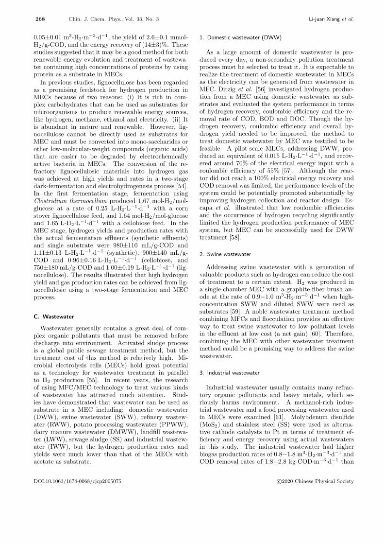
268 Chin. J. Chem. Phys., Vol. 33, No. 3 Li-juan Xiang et al.
0.05±0.01 m3-H2·m−3·d−1, the yield of 2.6±0.1 mmol-H2/g-COD, and the energy recovery of (14±3)%. Thesestudies suggested that it may be a good method for bothrenewable energy evolution and treatment of wastewa-ter containing high concentrations of proteins by usingprotein as a substrate in MECs.
In previous studies, lignocellulose has been regardedas a promising feedstock for hydrogen production inMECs because of two reasons: (i) It is rich in com-plex carbohydrates that can be used as substrates formicroorganisms to produce renewable energy sources,like hydrogen, methane, ethanol and electricity. (ii) Itis abundant in nature and renewable. However, lig-nocellulose cannot be directly used as substrates forMEC and must be converted into mono-saccharides orother low-molecular-weight compounds (organic acids)that are easier to be degraded by electrochemicallyactive bacteria in MECs. The conversion of the re-fractory lignocellulosic materials into hydrogen gaswas achieved at high yields and rates in a two-stagedark-fermentation and electrohydrogenesis process [54].In the first fermentation stage, fermentation usingClostridium thermocellum produced 1.67 mol-H2/mol-glucose at a rate of 0.25 L-H2·L−1·d−1 with a cornstover lignocellulose feed, and 1.64 mol-H2/mol-glucoseand 1.65 L-H2·L−1·d−1 with a cellobiose feed. In theMEC stage, hydrogen yields and production rates withthe actual fermentation effluents (synthetic effluents)and single substrate were 980±110 mL/g-COD and1.11±0.13 L-H2·L−1·d−1 (synthetic), 900±140 mL/g-COD and 0.96±0.16 L-H2·L−1·d−1 (cellobiose, and750±180 mL/g-COD and 1.00±0.19 L-H2·L−1·d−1 (lig-nocellulose). The results illustrated that high hydrogenyield and gas production rates can be achieved from lig-nocellulosic using a two-stage fermentation and MECprocess.
C. Wastewater
Wastewater generally contains a great deal of com-plex organic pollutants that must be removed beforedischarge into environment. Activated sludge processis a global public sewage treatment method, but thetreatment cost of this method is relatively high. Mi-crobial electrolysis cells (MECs) hold great potentialas a technology for wastewater treatment in parallelto H2 production [55]. In recent years, the researchof using MFC/MEC technology to treat various kindsof wastewater has attracted much attention. Stud-ies have demonstrated that wastewater can be used assubstrate in a MEC including: domestic wastewater(DWW), swine wastewater (SWW), refinery wastew-ater (RWW), potato processing wastewater (PPWW),dairy manure wastewater (DMWW), landfill wastewa-ter (LWW), sewage sludge (SS) and industrial wastew-ater (IWW), but the hydrogen production rates andyields were much lower than that of the MECs withacetate as substrate.
1. Domestic wastewater (DWW)
As a large amount of domestic wastewater is pro-duced every day, a non-secondary pollution treatmentprocess must be selected to treat it. It is expectable torealize the treatment of domestic wastewater in MECsas the electricity can be generated from wastewater inMFC. Ditzig et al. [56] investigated hydrogen produc-tion from a MEC using domestic wastewater as sub-strates and evaluated the system performance in termsof hydrogen recovery, coulombic efficiency and the re-moval rate of COD, BOD and DOC. Though the hy-drogen recovery, coulombic efficiency and overall hy-drogen yield needed to be improved, the method totreat domestic wastewater by MEC was testified to befeasible. A pilot-scale MECs, addressing DWW, pro-duced an equivalent of 0.015 L-H2·L−1·d−1, and recov-ered around 70% of the electrical energy input with acoulombic efficiency of 55% [57]. Although the reac-tor did not reach a 100% electrical energy recovery andCOD removal was limited, the performance levels of thesystem could be potentially promoted substantially byimproving hydrogen collection and reactor design. Es-capa et al. illustrated that low coulombic efficienciesand the occurrence of hydrogen recycling significantlylimited the hydrogen production performance of MECsystem, but MEC can be successfully used for DWWtreatment [58].
2. Swine wastewater
Addressing swine wastewater with a generation ofvaluable products such as hydrogen can reduce the costof treatment to a certain extent. H2 was produced ina single-chamber MEC with a graphite-fiber brush an-ode at the rate of 0.9−1.0 m3-H2·m−3·d−1 when high-concentration SWW and diluted SWW were used assubstrates [59]. A noble wastewater treatment methodcombining MFCs and flocculation provides an effectiveway to treat swine wastewater to low pollutant levelsin the effluent at low cost (a net gain) [60]. Therefore,combining the MEC with other wastewater treatmentmethod could be a promising way to address the swinewastewater.
3. Industrial wastewater
Industrial wastewater usually contains many refrac-tory organic pollutants and heavy metals, which se-riously harms environment. A methanol-rich indus-trial wastewater and a food processing wastewater usedin MECs were examined [61]. Molybdenum disulfide(MoS2) and stainless steel (SS) were used as alterna-tive cathode catalysts to Pt in terms of treatment ef-ficiency and energy recovery using actual wastewatersin this study. The industrial wastewater had higherbiogas production rates of 0.8−1.8 m3-H2·m−3·d−1 andCOD removal rates of 1.8−2.8 kg-COD·m−3·d−1 than
DOI:10.1063/1674-0068/cjcp2005075 c⃝2020 Chinese Physical Society

Chin. J. Chem. Phys., Vol. 33, No. 3 Microbial Electrolysis Cells for Hydrogen Production 269
the food processing wastewater. The overall energyrecoveries were positive for the industrial wastewater(3.1−3.8 kWh/kg-COD removed), while the food pro-cessing wastewater required a net energy input of −0.7to −1.2 kWh/kg-COD using MoS2 or Pt cathodes, and−3.1 kWh/kg-COD with SS, respectively.
V. ELECTROCATALYSTS FOR HYDROGENPRODUCTION IN MEC
The HER in MECs takes place at the cathode, it isnecessary to load electrocatalyst on the carbon materialto reduce the overpotential and promote the reactionrate. While MEC has attracted wide attention in re-cent years due to its superior performance for hydrogenevolution, there are still issues in practical application.However, there is still a lot of room for catalyst develop-ment in MEC performance improvement, which needsto prepare more efficient and stable catalysts with highcatalytic activity to promote the production of hydro-gen. It is found that the catalytic activity of ternaryor multi-component alloy is higher than that of binaryand single metal, and the performance of nano crys-talline electrode is better than that of ordinary alloy.If the multi-component nano crystalline electrode ma-terials can be prepared, the catalytic activity of theelectrode may be greatly improved. In MEC, platinumis the most commonly used catalyst, but its applica-tion is limited by its high cost and tendency to causeenvironmental pollution in the mining process. For along time, researchers have been committed to find anon-noble metal catalyst to replace Pt and use the non-noble metal-based electrocatalyst to carry out hydrogenevolution reaction (HER) at the cathode of MEC. It isnecessary to create and develop low-cost and efficientalternative catalysts, which can provide a promising av-enue for further development of hydrogen evolution inMEC.
A. Noble metal based electrocatalysts
Noble metals have the best catalytic performance forMEC, almost all precious metals can be used as cata-lysts, but the most commonly used ones are platinum,palladium, rhodium, etc., especially platinum. In thepast, it has been found that platinum group metals showhigh catalytic activity for MEC hydrogen evolution.Platinum group metals are easy to adsorb reactants andaccelerate the reaction because their d-electron orbitsare not full. Platinum shows good catalytic activityin MEC because of its large surface area and strongadsorption performance. However, platinum is easilypoisoned by carbon monoxide and sulfide [62]. Carbonmonoxide can be preferentially adsorbed on the activesites of Pt catalysis, so as to prevent the acquisition ofhydrogen and reduce catalyst activity. Sulfur pollutantsalso have an irreversible effect on the catalyst and havea negative impact on MEC.
B. Transition metals (TMs) as catalysts
Although platinum is the state-of-the-art electrocat-alysts for HER, its high cost and vulnerability by chem-icals limit its application. Therefore, the developmentof non-noble metal electrocatalysts to promote the re-lease of MEC hydrogen has become a hot researchtopic. Transition metal (TMs) compounds have at-tracted great attentions in MEC applications due totheir high conductivity and unique electronic structure.The outermost layer of transition metal element is notfully filled with electrons, so it tends to easily adsorbthe electrons of reactant with generation of interme-diate products to activate the adsorbed molecules. Inaddition, transition metal as solid catalysts usually ex-ists in the form of crystalline and abundance of activesites tend to appear on the surface, which can facilitatethe activity of reaction for reactant. TMs have grad-ually become the most popular catalytic material forHER in MEC. The structures, preparation methods ofsome typical transition metal compounds and their ef-fect on MEC hydrogen evolution will be summarized inthe following sections.
1. Transition metal phosphides
Transition metal phosphides (TMPs) are a new typeof catalytic materials for hydrogen evolution in MECfollowing transition metal carbide (TMC) and transi-tion metal nitride (TMN) [63]. TMPs have been widelyconcerned by researchers, because of its high catalyticactivity, high thermochemical stability and high con-ductivity in MEC. Therefore, the research on TMPs hasimportant theoretical significance and practical value.CoP is widely concerned in TMPs because of its low costand excellent catalytic activity, but its poor conductiv-ity affects its application in electrocatalysis. Wu et al.combined CoP with carbon nanotubes (CoP/CNTs),obtaining excellent HER performance, because the highspecific surface area of carbon nanotubes can acceler-ate the electron transfer and improve the conductivity,reaching the current density of 10 mA/cm2 at an over-potential of 139 mV [64]. When Cu3P was used as acatalyst for hydrogen evolution, a high over-potentialwas required to achieve a current density similar tothat of CoP. Du et al. synthesized Cu3P-CoP/CC byphosphating on carbon cloth [65], the synergistic ef-fect between metals increased the catalytic activity ofCu3P. Compared with Cu3P/CC and CoP/CC, Cu3P-CoP/CC achieved a current density of 10 mA/cm2 atoverpotential of 59 mV, showing great improvement to-ward electrocatalysis of HER. Du et al. also tried to im-prove the catalytic activity by further metal doping intoTMPs [66], they deposited aluminum on Ni2P nanowirearray (Al-Ni2P), which achieved a current density of10 mA/cm2 at overpotential of 129 mV and long-termchemical stability [67].
There are many ways to prepare TMPs. Liu et al.
DOI:10.1063/1674-0068/cjcp2005075 c⃝2020 Chinese Physical Society
270 Chin. J. Chem. Phys., Vol. 33, No. 3 Li-juan Xiang et al.
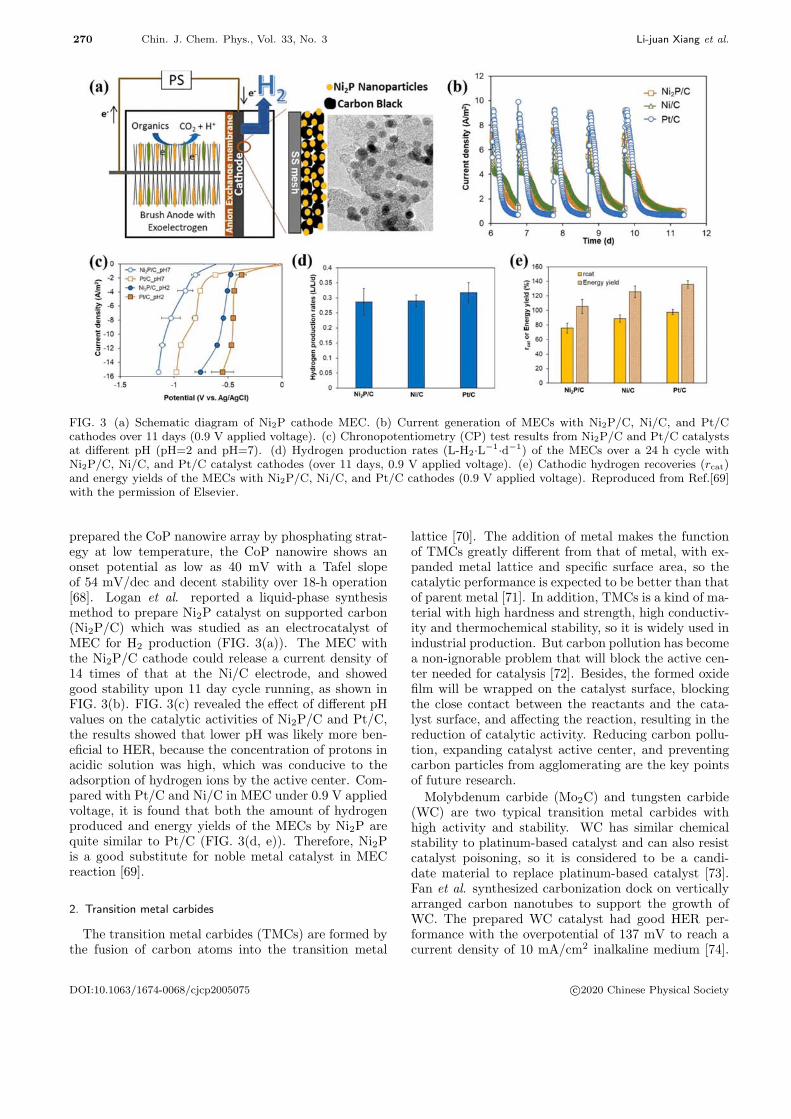
FIG. 3 (a) Schematic diagram of Ni2P cathode MEC. (b) Current generation of MECs with Ni2P/C, Ni/C, and Pt/Ccathodes over 11 days (0.9 V applied voltage). (c) Chronopotentiometry (CP) test results from Ni2P/C and Pt/C catalystsat different pH (pH=2 and pH=7). (d) Hydrogen production rates (L-H2·L−1·d−1) of the MECs over a 24 h cycle withNi2P/C, Ni/C, and Pt/C catalyst cathodes (over 11 days, 0.9 V applied voltage). (e) Cathodic hydrogen recoveries (rcat)and energy yields of the MECs with Ni2P/C, Ni/C, and Pt/C cathodes (0.9 V applied voltage). Reproduced from Ref.[69]with the permission of Elsevier.
prepared the CoP nanowire array by phosphating strat-egy at low temperature, the CoP nanowire shows anonset potential as low as 40 mV with a Tafel slopeof 54 mV/dec and decent stability over 18-h operation[68]. Logan et al. reported a liquid-phase synthesismethod to prepare Ni2P catalyst on supported carbon(Ni2P/C) which was studied as an electrocatalyst ofMEC for H2 production (FIG. 3(a)). The MEC withthe Ni2P/C cathode could release a current density of14 times of that at the Ni/C electrode, and showedgood stability upon 11 day cycle running, as shown inFIG. 3(b). FIG. 3(c) revealed the effect of different pHvalues on the catalytic activities of Ni2P/C and Pt/C,the results showed that lower pH was likely more ben-eficial to HER, because the concentration of protons inacidic solution was high, which was conducive to theadsorption of hydrogen ions by the active center. Com-pared with Pt/C and Ni/C in MEC under 0.9 V appliedvoltage, it is found that both the amount of hydrogenproduced and energy yields of the MECs by Ni2P arequite similar to Pt/C (FIG. 3(d, e)). Therefore, Ni2Pis a good substitute for noble metal catalyst in MECreaction [69].
2. Transition metal carbides
The transition metal carbides (TMCs) are formed bythe fusion of carbon atoms into the transition metal
lattice [70]. The addition of metal makes the functionof TMCs greatly different from that of metal, with ex-panded metal lattice and specific surface area, so thecatalytic performance is expected to be better than thatof parent metal [71]. In addition, TMCs is a kind of ma-terial with high hardness and strength, high conductiv-ity and thermochemical stability, so it is widely used inindustrial production. But carbon pollution has becomea non-ignorable problem that will block the active cen-ter needed for catalysis [72]. Besides, the formed oxidefilm will be wrapped on the catalyst surface, blockingthe close contact between the reactants and the cata-lyst surface, and affecting the reaction, resulting in thereduction of catalytic activity. Reducing carbon pollu-tion, expanding catalyst active center, and preventingcarbon particles from agglomerating are the key pointsof future research.
Molybdenum carbide (Mo2C) and tungsten carbide(WC) are two typical transition metal carbides withhigh activity and stability. WC has similar chemicalstability to platinum-based catalyst and can also resistcatalyst poisoning, so it is considered to be a candi-date material to replace platinum-based catalyst [73].Fan et al. synthesized carbonization dock on verticallyarranged carbon nanotubes to support the growth ofWC. The prepared WC catalyst had good HER per-formance with the overpotential of 137 mV to reach acurrent density of 10 mA/cm2 inalkaline medium [74].
DOI:10.1063/1674-0068/cjcp2005075 c⃝2020 Chinese Physical Society

Chin. J. Chem. Phys., Vol. 33, No. 3 Microbial Electrolysis Cells for Hydrogen Production 271
However, the currently prepared WC particles have alow surface area, and it is easy to form thick oxide filmto prevent reactants from entering the active center,thereby reducing the catalytic activity of WC. Com-pared with WC, Mo2C has a better catalytic effect onMEC cathode and has been widely used. Lin et al.[75] doped Co into the Mo2C crystal structure with aCo/Mo ratio of 0.020, increasing the electronic densityof state of Fermi level and improving the catalytic ac-tivity. In 1.0 mol/L KOH solution, the current densityat Co-Mo2C electrode was 10 mA/cm2 at overpotentialof 118 mV, providing a feasible strategy to explore ef-ficient electrocatalysts for hydrogen evolution in MECby engineering on composition and nanostructure.
Although TMC shows favorable catalytic activity to-ward HER, but there are still some issues in the cat-alytic process, including the difficulty in preparing cata-lyst with high specific surface area and the optimizationof catalytic conditions.
3. Transition metal nitrides
Like TMCs, transition metal nitrides (TMNs) arefilled with nitrogen atoms in the voids of metal latticestructure, which leads to the change of the electronicstructure of the d-band [76]. These nitrides have theadvantages of high hardness, chemical corrosion resis-tance, high conductivity and thermal stability. Thereare many TMNs catalysts, such as molybdenum nitride(MoN), tungsten nitride (WN), nickel nitride (Ni3N)and cobalt nitride (Co4N). Among them, MoN is themost widely used because of its excellent catalytic per-formance. Ramesh et al. [77] synthesized MoNx/NFcatalyst on nickel foam by atomic layer electrodepo-sition (ALD). In acidic medium, the MoNx/NF onlyneeded 148 mV overpotential to approach current den-sity of 10 mA/cm2, likely because the Mo-N covalentbond enhanced the electron density of d-band, whichcontributed to higher catalytic activity than bare NF.Mo5N6 nanoflakes were synthesized by salt templatemethod [78] with Mo/N ratio of 5:6, which increasednitrogen content and showed better catalytic activitythan that of TMN in different electrolytes. The highvalence state of Mo element and a large amount of nitro-gen doping make Mo5N6 have the electronic structuresimilar to platinum, so it has high catalytic activity.
TMN materials with excellent catalytic performanceneed more active centers and nanoparticles with uni-form distribution. The methods to prepare TMN in-clude temperature programmed reaction method (TPR)[79], synthesis of metal nitrides by the pulsed laserdeposition (PLD) [80], reactive magnetron sputteringmethod [81], TPR is a method of mixing metals, metaloxides, metal organics with ammonia and then throughnitriding to obtain metal nitrides. Different precursorand nitrogen will produce nitride products with differ-ent shape. The particle size and pore structure of metalnitride will be affected by precursor material, prepara-
tion temperature and nitriding conditions. Therefore,reaction conditions shall be reasonably controlled dur-ing preparation to ensure that materials with high cat-alytic activity are obtained.
The excellent catalytic performance of TMN makes itattract much attention in the field of catalysis, but itsmetastable characteristics often form impurities such asmetal, oxide, hydroxide, etc. It is unclear what effectthese impurities have on the catalytic performance andshould be paid attention to in future research. Amongthe metal nitrides, MoN has good catalytic activity andplays an important role in the MEC hydrogen produc-tion process. The application of other new nitrides(such as cobalt nitride and tungsten nitride) in MEChydrogen evolution is also a new research direction.
4. Stainless steel alloy cathodes
Stainless steel (SS) has good corrosion resistance andlow price. In MEC, the cathode made of stainlesssteel with a high specific surface area can achieve cat-alytic performance similar to that of platinum-basedcatalysts. Furthermore, Munoz et al. reported thatstainless-steel cathode showed good catalysis perfor-mance with the hydrogen flow rate of 4.9 L-H2·m−2·h−1
(11.2 A/m2) under the applied voltage of 0.8 V in weakalkaline solutions (pH=8) [41]. It has been found thatthe stainless-steel cathode material with high specificsurface area can replace the noble metal catalyst toobtain a good hydrogen yield. Under the voltage of0.6 V, using a stainless-steel brush cathode with a spe-cific surface area of 810 m2/m3, the hydrogen produc-tion rate can reach (1.7±0.1) m3-H2·m−3·d−1. Thisstudy showed that although the specific surface area ofreactor horizontal brush (HB) was larger than that ofreactor vertical brush (VB), the produced current den-sity of HB was lower than that of VB. It meant thatthe electrode spacing can avoid ohmic loss, which wasalso the reason why the performance of reactor VB wasbetter than HB [82]. The most studied three types ofstainless steel as catalysts are SS304, SS316 and SS430containing 9.25%, 12%, and 0.75% nickel respectively.Stainless steel 316 had the highest nickel content, it wasfound that it was the best cathode material in alkalinemedium by electrochemical test [83]. As a low-cost cat-alytic material, stainless steel mesh has been used inMEC research recently. When the stainless-steel meshis used in MEC, the hydrogen production catalysis per-formance can be affected by its structure. Under lowcurrent density and small bubble coverage, the meshdiameter is the main factor affecting the hydrogen pro-duction rate, while under high current density and highbubble coverage, the mesh size is the main factor affect-ing the hydrogen production rate [84].
5. Nickel and Ni-based alloys
Nickel-based catalytic materials have been concernedto be comparable to platinum-based catalysts in the
DOI:10.1063/1674-0068/cjcp2005075 c⃝2020 Chinese Physical Society

272 Chin. J. Chem. Phys., Vol. 33, No. 3 Li-juan Xiang et al.
TABLE II The comparison of hydrogen evolution parameters of different catalysts in MEC.
Cathode catalyst type Eps/V CCE/% OCE/% CE/% EE/% Reference
Ni particles 1 106 82a [88]
Carbon nanotubesb 0.9 62 81 117 [87]
Pt/Carbon nanotubesb 0.9 65 94 126 [87]
Ptc 0.8 80 45.2 56 [90]
Pt/Cd 0.4 94 81 86 216 [86]
Ni/Cd 0.4 99 73 74 197 [86]
PtNi/Cd 0.4 94 77 82 199 [86]
Cu/Cd 0.4 92 65 71 188 [86]
PtCu/Cd 0.4 95 73 77 165 [86]
Note: CCE-cathodic conversion efficiency, OCE-overall hydrogen conversion efficiency.a Calculated based on the given data.b Single-chambered MEC without a membrane.c Two-chambered MEC.d Single-chambered MEC with a membrane.
TABLE III Summary of the H2 production performance in MECs with difference cathodic catalysts.
Cathode Anode Eps/V Iv/(A/m2) Q/(m3-H2·m−3·d−1) rH2,cat/% ηE/% CE/% Ref.
NiW/Ni-foam Carbon felt 0.6 250 0.14 78.9 205.2 [40]
NiMo/Ni-foam Carbon felt 0.6 125 0.13 88.6 238.4 [40]
Ni2P Graphite brush 0.9 3.5 0.29 76 152 [69]
Ni mesh Graphite felt 1.1 312 4.18 89.3 75 [42]
CoPNF Graphite brush 0.7 0.22 39 90 [97]
NiP/NF Carbon bush 0.9 2.29 94.7 152.6 91.7 [98]
MoS2@CNT Carbon bush 0.8 0.01 49.0 144.4 [99]
MoS2/graphene Carbon felt 0.7 9.96 0.424 78.86 227.5 89.11 [92]
NanoMg(OH)2/graphene Carbon felt 0.7 9.21 0.63 83 212 83 [91]
NFe/Fe3C@C Carbon cloth 0.8 0.0144 79.5 38.1 [96]
SS brush Graphite fiber 0.6 188 A/m3 1.7 83 221 [82]
Note: Iv: current density, rH2,cat: cathodic hydrogen recovery, Eps: applied voltage, ηE: energy efficiency, Q: hydrogenproduction rate, CE: coulombic efficiency.
catalytic activity and efficiency of hydrogen productionand the high conductivity, so they are most likely toreplace platinum-based catalysts [85]. The compari-son of parameters of different catalysts in MEC hy-drogen evolution is shown in Table II [86]. It showsthat Ni/C is not as good as Pt/C in catalytic perfor-mance. Whether nickel is used alone or in combinationwith other metals, its catalytic performance is superiorto other metal-based materials. The energy efficiencyof Ni/C is 197%, and the highest conversion is 99%.The coulombic efficiency and energy efficiency of car-bon nanotubes are lower than those of other catalysts[87, 88]. Although carbon nanomaterials have a largesurface area, the carbon nanomaterials without metaldoping still have great limitations in catalysis. Anotherstudy [89] used Pt wrapped nickel foam (NF) as a cat-alytic material. Compared with Pt/CC and NF, theenergy efficiency of Pt/NF under 0.8 V applied volt-age was 127%, higher than that of Pt/CC and NF,
and the highest hydrogen production rate of the cath-ode was 0.71±0.03 m3-H2·m−3·d−1, which exceeded the0.67±0.02 m3-H2·m−3·d−1 of Pt/CC, The reason is thatthe porous structure of nickel foam provides more ac-tive sites than planar carbon materials and has greatercatalytic activity. However, during MEC operation, theporous structure of nickel foam causes nickel corrosionand increase cathodic overpotential, which will bringenergy loss. Because of the low overpotential, electro-formed nickel mesh is used as a substitute for plat-inum catalyst. When the applied voltage was 1.1 V,the hydrogen production rate of MEC was 4.18±1 m3-H2·m−3·d−1 at the current density of 312±9 A/m3,which was slightly lower than that of MECs with Ptcatalyst (4.25±1 m3-H2·m−3·d−1, 314±5 A/m3) [42].The cost of electroformed nickel mesh is low, so it ispromising to be widely used in MEC.
The porous structure of nickel foam can cause cor-rosion of nickel. Plating tungsten and molybdenum on
DOI:10.1063/1674-0068/cjcp2005075 c⃝2020 Chinese Physical Society

Chin. J. Chem. Phys., Vol. 33, No. 3 Microbial Electrolysis Cells for Hydrogen Production 273
nickel foam can improve corrosion resistance. In a sin-gle chamber membrane free MEC reactor, the hydrogenevolution performance of the electrodes has been testedin neutral phosphate buffer by adding the voltage of0.6 V. The result showed that the current density (250and 125 A/m2), hydrogen production rate (0.14±0.01and 0.13±0.01 m3-H2·m−3·d−1), cathodic hydrogen re-covery rate ((78.9±1.7)% and (88.6±2.3)%) of NiW andNiMo cathodes were both higher than that of bare nickelfoam [40]. In order to improve the practical feasibilityof hydrogen production in MEC, the performance ofcatalyst should be further optimized.
C. Nanostructured materials as catalysts
In recent years, great progress has been made in us-ing nano materials as cathode catalysts. Nano mate-rials include nano particles, nano films, nano crystals,etc. The tiny structure and large specific surface areaof nanomaterials greatly increase the contact area withthe reactants, which is why it is used as a new MEChydrogen production catalyst.
Dai et al. [91] prepared nano-Mg(OH)2/graphenecomposite by using hydrothermal synthesis withMgSO4·7H2O and graphene oxide (GO) as precur-sors. The results of LSV showed that the best hy-drogen production was obtained when the ratio ofMgSO4·7H2O to GO was 1:1. The results showed thatthe hydrogen production of nano-Mg(OH)2/graphenewas better than that of Pt/C, but the catalytic ac-tivity and energy efficiency of the former were sim-ilar to that of the latter. Dai also used the bestraw material ratio of (NH4)2MoS4 to GO of 1:1,MoS2/graphene composite was also prepared by hy-drothermal synthesis method [92]. The results weresimilar to nano-Mg(OH)2/graphene. In the experi-ment of MEC hydrogen production, the current den-sity, hydrogen production rate and coulombic efficiencyof MoS2/graphene cathode were 9.96±0.65 A/m2,0.424±0.04 m3-H2·m−3·d−1 and (89.11±5.87)% respec-tively, which were higher than those of Pt/C. The goodhydrogen evolution performance of MoS2 in MEC hasbeen confirmed, but its electrochemical behavior needsto be further explored. The catalytic activity of MECwas tested under two different electrode structures. Thefirst electrode structure was to deposit MoS2 on stain-less steel. The SS electrode polished with MoS2 hadmore catalytic activity than that uncoated MoS2, forthe active sites of the polished MoS2 exposed, resultingin higher catalytic activity [93]. The second electrodestructure was to combine MoS2 with carbon black. Bychanging the optimal load of MoS2 composite cathode,the surface density of catalyst is affected. After LSVscanning in sodium perchlorate solution (NaClO4), theoptimal load was 54 mg MoS2 and 60 mg carbon black,and the surface density was 45 g/m2 [94]. This com-posite nano material has advantages due to its low cost
and simple synthesis process.It is known that different electrode structures have in-
fluence on the catalytic activity of MEC cathode. Chenet al. [95] synthesized an excellent nano material, whichhad good hydrogen evolution performance in a widerange of pH. Ni-N-MoCx doped with Ni-N was syn-thesized by the mixture of NiMoO4 and C2H4N4. Inthe alkaline medium, the initial potential was −37 mV,the overpotential was 124 mV, and the current den-sity was 10 mA/cm2. In the acid medium, the initialpotential was −74 mV, the overpotential was 163 mV,and the current density was 10 mA/cm2. The Co dop-ing of Ni and N increased the HER activity in MEC.Another new type of catalyst N-Fe/Fe3C@C with ni-trogen core-shell structure, also showed good hydrogenevolution performance in MEC. The new catalyst tookiron-based composite (Fe/Fe3C) nanorods as the coreand graphite carbon as the shell. It showed good hy-drogen evolution activity and stability in MEC. Un-der 0.8 V applied voltage, the peak current density ofN-Fe/Fe3C@C was 2.60±0.07 A/m2, higher than CCcathode (1.36±0.01 A/m2) and carbon nanotube cath-ode (1.30±0.09 A/m2) [96]. The low cost and simplesynthesis process of the composite nanomaterials makethem have advantages and can be used as catalysts toreplace precious metals.
Catalyst plays an important role in improving hydro-gen production of microbial cell. Table III summarizesthe influence parameters of different kinds of catalyst onMEC hydrogen evolution performance, providing refer-ence for finding efficient and stable catalyst.
The typical Pt-free catalysts developed in the recentyears for HER in MEC are summarized in FIG. 4. Asit depicts transition metal-based catalysts (especiallynickel) and nanomaterials attracted more attention inthe recent few years. With the rapid development ofplatinum alternative catalysts, it is believed that ap-plication of MEC technology for hydrogen productionbecomes more and more prospective.
D. Biocathode in MEC
The bio-electrode MEC can be divided into semi-bio-electrode MEC and full-bio-electrode MEC according tothe location of microorganisms. Semi-biological cath-odes are divided into anode microorganism MEC andcathode microorganism MEC according to the role ofmicroorganisms in the hydrogen evolution process ofMEC (FIG. 5).
1. Single microbial biocathode MEC
The MEC cathode is where hydrogen gas is gener-ated, so the performance of the MEC cathode will di-rectly affect the hydrogen production to a large extent.In addition to the use of metal catalysts, the study ofmicroorganisms as cathode catalysts has also been in-cluded in the list of MEC cathode catalyst research,because its cost is lower than chemical catalysts, it can
DOI:10.1063/1674-0068/cjcp2005075 c⃝2020 Chinese Physical Society

274 Chin. J. Chem. Phys., Vol. 33, No. 3 Li-juan Xiang et al.
FIG. 4 Development of MEC catalyst for hydrogen production.
FIG. 5 Schematic diagram of semi-biological MEC and full-biological MEC.
generate itself, and does not produce secondary pollu-tion and other advantages. Although the current den-sity of biocathode MEC is lower than that of traditionalelectrolytic cell, the advantage of low cost makes it havethe potential for further exploration [100, 101]. Bio-cathode is a welcome advancement in the practical ap-plication of wastewater treatment, metal ion recovery,and preparation of chemical products such as hydrogen.
In 2008, Rozendal et al. [101] for the first time re-ported that the anode used acetate and the cathodeused microorganisms to catalyze hydrogen evolution.By reversing the polarity of the electrode, a bioanodeof acetate and hydroxide was converted into a biocath-ode that produced hydrogen. In this way, the MEC
can achieve a current density of −1.2 A/m2 at an ap-plied voltage of 0.7 V, which was 3.6 times that ofthe blank control electrode. In addition, the micro-bial biocathode electrode has a cathode hydrogen ef-ficiency of 49% and a hydrogen generation rate of 0.63m3-H2·m−3·d−1, while the control electrode cathode hy-drogen efficiency was 25% and a hydrogen generationrate of 0.08 m3-H2·m−3·d−1. SEM images of both mi-crobial electrodes showed a well-developed biofilm onthe electrode surface.
In order to compare the difference between the perfor-mance of microbial cathode MEC and ordinary chem-ical catalysts for hydrogen evolution of MEC, explorethe reason why the rate of hydrogen evolution of bio-
DOI:10.1063/1674-0068/cjcp2005075 c⃝2020 Chinese Physical Society

Chin. J. Chem. Phys., Vol. 33, No. 3 Microbial Electrolysis Cells for Hydrogen Production 275
cathode MEC was lower than that of chemical cata-lysts, Jeremiasse et al. [102] found that biocathodecould also realize hydrogen production under suitableconditions, and the more microorganisms on the elec-trode, the more helpful it was to improve the currentdensity and hydrogen production effect of MEC. How-ever, when using a metal catalyst relative to MEC, thehydrogen production rate of the biocathode was low,only 0.04 L-H2·L−1·d−1, which was 2 orders of magni-tude lower than the metal catalyst. Although the speedof hydrogen preparation by using biological cathode wasimproved, it was only 0.30 L-H2·L−1·d−1 [103]. Cath-ode microorganism growth rate is too slow and the neg-ative impact of cathode precipitates on hydrogen pro-duction efficiency may be the main reason for the lowrate of hydrogen production of biocathode MEC.
Temperature is one of the important factors thataffect the hydrogen evolution performance of MEC,mainly because the activity of microorganisms is greatlyaffected by temperature. In 2013, Fu et al. [104]reported for the first time a dual-chamber high-temperature biocathode that did not need to changethe polarity of the hydrogen evolution MEC. The an-ode was a carbon cloth that was not inoculated withmicroorganisms. The CV curve showed that the reduc-ing activity of the biocathode was significantly higherthan that of the control electrode, which verified thecatalytic activity of the microorganism. And under theapplied voltage of 0.8 V, the current density and hydro-gen yield produced by the thermophilic biocathode were10 times that of the uninoculated control cathode. Andthe recovery rate of cathode hydrogen reached 72%.
In 2017, Jafary et al. [105] used sulfate-reducingbacteria as catalysts for the MEC cathode hydrogenevolution reaction, by changing the cathode electrolytepH from 3.5 to 6.5, the applied voltage from 0.6 Vto 1.3 V, and the sodium sulfate concentration from0.1 g/L to 1.0 g/L, explored the effect of pH, appliedvoltage and catholyte concentration on MEC hydro-gen evolution performance. The results showed thata medium rich in H2, acidic (pH=4), and low sulfatecontent (0.2 g/L) accelerated the formation of a bio-cathode and increased the rate of hydrogen generation.Compared with the uninoculated graphite felt cathode,the biocathode MEC’s HER potential was reduced by430 mV, and the hydrogen production was increased bya factor of six, and the energy required for the HER re-action of about 1 kWh/m3 was saved compared to theuninoculated graphite felt cathode. This report pro-vides a new way for the clean production of hydrogenin biocathode MECs.
2. Chemical catalyst synergistically coupled with microbialbiocathode MEC for hydrogen evolution
Cathode reaction catalysts of MEC usually use a cer-tain chemical catalyst or a certain type of microbial cat-alyst alone to attach a conductive carrier to catalyze the
hydrogen evolution reaction, but there is little researchon the chemical catalyst and microorganisms catalyzingthe hydrogen evolution of MEC cathode together. Chenet al. [106] prepared PANI/MWCNT composite mate-rials and used the synergistic coupling effect betweenthe materials and cathode microorganisms to improvethe hydrogen evolution performance of single-chambermembrane-less MEC. Compared with pure biocathodewithout modification of composite materials, the mod-ified biocathode had higher current density. And theresearch showed that the types of microorganisms andthe homogeneity of the microorganisms in the modifiedbiocathode were different from those in the unmodifiedbiocathode. The Pearson correlation coefficient of thetwo cathodes was only 32.09%, indicating the differencein the types and numbers of microorganism. When theapplied voltage was 0.9 V, the hydrogen production rateof the composite material modified microbial cathodewas 0.67 m3-H2·m−3·d−1, the coulombic efficiency was72%, the cathode hydrogen recovery rate was 42%, andthe input power efficiency was 81%. This research pro-vides a new idea for the study of the combination ofcommon chemical catalysts and microbial biocathode.
3. Full biocathode MECs
The common dual-chamber MEC hydrogen evolutionreactor uses a microbial anode for the anode, and anon-biological common chemical catalyst cathode forthe cathode [97, 107, 108]. However, because the costof preparing such a cathode is too high, researchers be-gan to develop MEC hydrogen production reactors inwhich both the cathode and anode are microorganisms.Table IV is a categorical display of the effect on thehydrogen evolution performance of the MEC using bio-cathode.
In 2008, the microbial biocathode MEC developedby Rozendal was a semi-biological MEC hydrogen evo-lution reactor [101]. Therefore, in 2010, Jeremiasse etal. began to study the full bioelectrode hydrogen evo-lution MEC whose cathode and anode were both mi-croorganisms. The principle of microbial catalytic cath-ode and anodic oxidation and reduction reactions inMEC were investigated. At the same cathode potential(−0.7 V), the microbial biocathode MEC (3.3 A/cm2)had a higher current density than the non-biocathodeMEC (0.3 A/m2) using graphite felt. However, com-pared with the Pt cathode MEC, the start-up time ofthe full biocathode MEC was longer. This study showedthat the current density of the full biocathode MEC wasgreater than the semi-biocathode MEC [102].
Recently, in order to compare the difference betweenfull bioelectrode hydrogen evolution MEC and semi-biological hydrogen evolution MEC. Jafary et al. [109]developed a MEC with both cathode and anode mi-croorganisms. After cultivating the microbes of the an-ode and cathode with semi-bio anode MFC (HB-MFC)and semi-bio cathode MEC (HB-MEC), respectively,
DOI:10.1063/1674-0068/cjcp2005075 c⃝2020 Chinese Physical Society

276 Chin. J. Chem. Phys., Vol. 33, No. 3 Li-juan Xiang et al.
TABLE IV Effects of cathode and/or anode microorganisms on MEC hydrogen evolution performance.
Anode Cathode Iv rcat/% CE/% Q/(m3-H2·m−3·d−1) Ref.
Graphite felt Graphite felt biocathode 1.1 A/m3 0.63 [110]
Graphite felt Graphite felt biocathode 1.2 A/m2 49 0.63 [101]
Graphite felt Graphite felt biocathode 0.702 A/m2 147 31 0.301 [103]
Graphite felt H2, Graphite felt biocathode 15 A/m2 1.85 [111]
Carbon cloth Carbon cloth biocathode 1.28 A/m3 70 0.3765a [111]
Graphite felt Graphite felt biocathode 2.3 A/m3 2.7 [112]
Carbon felt Carbon paper biocathode 14.75 A/m3 79.42 88.92 0.428 [113]
Carbon felt Carbon felt with biocathode 1.1 A/m2 10b [114]
Carbon fiber brush RGO modified biocathode/CC 14.07 A/m2 2.49 [115]
Carbon cloth with Pt Carbon cloth with materials biocathode 205 A/m3 42 72 0.67 [106]
Graphite felt bioanode Graphite felt biocathode 2.5 A/m2 0.45 [109]
Carbon cloth bioanode Carbon cloth biocathode 134 A/m3 0.39 37 63 [116]a With the unit of mol-H2· m−2·d−1.b With the unit of L-H2·m−2·d−1.
using their anodes and cathodes to assemble a full bioMEC hydrogen evolution reactor (FB- MEC). When theoxidation reaction of the MEC anode and the reductionreaction of the cathode were biocatalyzed by the biofilmattached to the electrode in the FB-MEC, the initial po-tential of the HER of the non-biological control systemwas reduced by 500 mV, and the maximum current den-sity was also increased by 6.5 times. But compared withHB-MEC, the hydrogen evolution rate of FB-MEC wasreduced. However, the cathode hydrogen recovery rateincreased from 42% to 65%, indicating that the effectiveoxidation and reduction efficiency of the full bio-MECreactor were higher than that of the semi-bioreactor.
VI. PARAMETERS AFFECTING MECS OPERATION
The hydrogen evolution performance of MEC was af-fected by many factors, such as the structure of the elec-trolytic cell, the activity of the anode microorganisms,the materials that constitute the electrolytic cell, andthe environment in which the battery operates. Theseshould affect the hydrogen evolution efficiency of theMEC. Additionally, MEC is a technology developed onthe basis of microbial fuel cell. Therefore, the factorsthat affect the activity of MFC anode are also parame-ters affecting the MEC anode microorganism electricitygenerating ability. Understanding these influencing fac-tors of MEC hydrogen evolution performance can helpto reduce or eliminate the influence of these factors asmuch as possible, thereby improving the MEC hydrogenevolution rate, and providing help for the practical pro-motion and application of MEC hydrogen productiontechnology in the future. In this section, the influenceof temperature, catholyte pH, applied voltage, and cat-alyst activity on MEC hydrogen evolution performanceare discussed.
A. Temperature
During the operation of the MEC, temperature is oneof the important parameters that affect microbial activ-ity, dominant strains, and reactor performance. Appro-priate culture temperature has a positive effect on mi-crobial reaction kinetics, accelerating the reaction rateon the cathode and increasing the rate of proton trans-fer in the reaction solution. The performance of MECand the speed and structure of anode biofilm forma-tion were affected by the temperature. Previous stud-ies have shown that temperature affects the anode po-tential of the MEC, which actually represents the lifemetabolism activity of anode microorganisms [117]. Al-though the living temperature range of microorganismsis very wide, the operating range of temperature inMFC and MEC is very narrow, generally 20−45C,because most microorganisms show higher activity inthis temperature range [98, 118, 119]. The operationof the laboratory MEC is generally at room tempera-ture (25 C). The optimal temperature of the contin-uous MEC reactor is 30 C to 35 C [100, 120, 121].If the temperature is too high, it will be detrimentalto the activity of electricity-producing microorganisms[120, 122].
Kyazze et al. [120] used a two-chamber concentrictubular microbial electrolysis cell, in which the anodesubstrate was sodium acetate, the pH of the anolyte wascontrolled to be around 7.4 by adding 1.2 mol/L HCl,and the catholyte was a 50 mmol/L phosphate buffer(PBS) with pH 7.0. The applied voltage was about0.92 V (vs. Ag/AgCl). They studied the current den-sity variation of MEC and hydrogen production withtemperature. Current density and hydrogen produc-tion both increased in the range of 20−30 C, and thendecreased as the temperature rised to 53 C. The op-timal operating temperature of MEC was about 30 C
DOI:10.1063/1674-0068/cjcp2005075 c⃝2020 Chinese Physical Society

Chin. J. Chem. Phys., Vol. 33, No. 3 Microbial Electrolysis Cells for Hydrogen Production 277
FIG. 6 Influence of temperature and initial anolyte pH on hydrogen production. (a) Current change of the MEC system atdifferent initial anolyte pH. (b) Effect of the initial anolyte pH value on hydrogen production of the MEC system. (c) Currentchange of the MEC system at different temperatures. (d) Effects of temperature on hydrogen production. Reproduced fromRef.[124] with the permission of Elsevier.
(173 mL·L−1anode·d−1, current density was 1.69 A/m2),
and the average hydrogen generation rate was 56.5mL/d. At room temperature (23±1.4 C), the averagehydrogen generation rate of MEC is 42.2 mL/d (currentdensity is 1.33 A/m2). After the study temperature wasraised to 53 C, the anode microorganism recovered itsactivity after dropping to room temperature, indicatingthat the MEC anode electricity-producing microorgan-ism had a higher elasticity to temperature. In addition,the optimal temperature of MEC is 30 C, which alsoshows that the practical application of MEC is suitablefor countries with higher temperatures.
However, other studies have shown that when glu-cose was used as a substrate, hydrogen can also begenerated by MEC at low temperature (4 C). Luet al. [123] used a single-chamber membrane-lessMEC [52] to prove that under low temperature (4C) conditions, glucose-fermenting bacteria can survivein large quantities, and decompose glucose to gener-ate electrons and obtain hydrogen. And the hydro-gen yield at low temperature (6 mol-H2/mol-glucosetherate was (0.25±0.03)−(0.37±0.04) m3-H2·m−3· d−1)was equivalent to that under medium temperature (25C, 5.8 mol-H2/mol-glucose, the rate was 1.01 m3-H2·m−3·d−1). In addition, this study shows that an-other isotropic interaction in the MEC at 25 C, suchas methane production and homolactic acid produc-tion, was slightly undetectable at 4 C since Dys-
gonomonas (36.6%) is the main microorganisms insteadof methanogens or others at low temperature. And at25 C, bacteroides (accounting for 21.5% of the commu-nity) is the main genus in MEC isolates. This researchhas laid a certain foundation for the development ofMEC using only carbohydrates to produce hydrogen atlow temperatures. Furthermore, Wang et al. [124] stud-ied influence of temperature and electrolyte pH on hy-drogen production through simultaneous saccharifica-tion and fermentation (SSF) of lignocellulose in MEC.The influence of temperature and electrolyte pH on hy-drogen production is shown in FIG. 6. It indicates thata moderate temperature (35−40 C) of initial anolyteis suitable for the growth and metabolism of exoelectro-genic microbes and can improve metabolic activities ofthese microbes and cellulase during SSF. While a nearneutral pH condition is appropriate for the growth andactivity of the microbials in MEC to promote hydrogenproduction performance.
B. Electrolyte pH
The nature of catholyte in MEC is another impor-tant parameter that affects its hydrogen evolution ef-ficiency. There are many electrolytes used to studythe hydrogen evolution of MEC. The pH of the elec-trolyte will affect the activity of electrochemically ac-tive bacteria and be used to control the redox reac-
DOI:10.1063/1674-0068/cjcp2005075 c⃝2020 Chinese Physical Society

278 Chin. J. Chem. Phys., Vol. 33, No. 3 Li-juan Xiang et al.
TABLE V Coulombic efficiency and hydrogen production of different catholytes in MEC [125].
Catholytes Time period/day CE/% rcat/% rH2/% QH2/(m3-H2·m−3·d−1)
100 mmol/L PBS 1.44 34.6 89.2 30.8 0.237
50 mmol/L PBS 1.06 18.7 89.2 16.7 0.165
25 mmol/L PBS 1.11 13.2 80.1 10.6 0.100
10 mmol/L PBS 1.29 8.0 69.9 5.6 0.048
134 mmol/L NaCl 2.01 26.5 120.4 31.8 0.171
100 mmol/L NaCl 1.55 19.8 91.2 18.0 0.116
200 mmol/L NaCl 1.30 19.7 93.7 18.4 0.143
DI water 5.10 42.8 67.9 28.5 0.065
Tap water 3.14 10.9 93.8 9.8 0.034
Acidified water (pH=4) 2.81 11.0 156.3 17.0 0.065
Acidified water (pH=2)a 1.19 21.5 84.7 18.2 0.171
Acidified water (pH=2)b 1.37 18.5 65.5 12.0 0.089a Adjusted by sulfuric acid.b Adjusted by hydrochoric acid.
tion potential on the electrode. In addition, it alsoaffects the activity of methanogenic bacteria [43, 125,126]. Therefore, the following work has been doneto study the effect of MEC electrolyte pH on hydro-gen evolution performance. Kyazze et al. [120] haveshown that running at a low pH cathode can increasethe rate of hydrogen production and reduce the totalelectrical energy added to the system. When a volt-age of 0.6 V was applied, the order of cathode over-voltage was pH=5 (152 mV)>pH=7 (132 mV)>pH=9(116 mV). In addition, Yossan et al. [125] studied theeffects of 12 electrolyte solutions with different pH val-ues on the hydrogen yield of the dual-chamber MECat 20 C, 0.8 V applied voltage, and 10 Ω resistance.The results of the study are presented in Table V. Themaximum hydrogen yield (QH2) of 100 mmol/L PBS(pH=9.2) can reach 0.237 m3-H2·m−3·d−1, and the hy-drogen yield of electrolytes with different concentrationsof NaCl was also relatively high. 134 mmol/L NaCl(pH=12.2) can reach 0.171 m3-H2·m−3·d−1, in addi-tion, the acidic electrolyte (pH=9.0) adjusted with sul-furic acid also showed excellent hydrogen production ef-fect (QH2=0.171 m3-H2·m−3·d−1). However, the acidicelectrolyte with pH adjusted by sulfuric acid (pH=11.9)had the lowest hydrogen yield, even the same as thatof deionized water. Rago et al. [127] learned throughresearch that compared with the neutral electrolyte(pH=7.3), alkaline (pH=9.3) bioelectrochemical hydro-gen production performance was better than conven-tional neutral electrolyte, which can reach hydrogenproduction efficiency of 2.6 vs. 1.2 LH2 ·L−1
Reactor·d−1 andcurrent density of 50 mA/m2.
Recently, Wang et al. [128] used a double-chamberglass tube MEC hydrogen evolution reactor with a bipo-lar membrane (BPM) as a diaphragm, with an externalresistance of 10 Ω, an external voltage of 0.9 V andsulfuric acid as its catholyte. In order to explore the
effect of pH on the hydrogen evolution performance ofMEC, the catholyte H concentration was changed. Theresults showed that the maximum current density ofMEC decreased almost linearly with the increase of pHin the pH range of 0.5−3.5, and the maximum currentdensity was obtained when pH=0.3. However, whenthe electrolyte was changed to a phosphate buffer so-lution with pH=7.5, the jmax of MEC was similar tothat at pH=3.5, reflecting the importance of the H con-centration (pH) in the electrolyte and the catholyte’sproton concentration had a great limitation on the per-formance of MEC when pH was low. It also shows thatthe acidic electrolyte used by MEC can effectively in-crease its current density compared with the traditionalneutral electrolyte.
C. Applied voltage
From a thermodynamic point of view, MEC hydro-gen evolution is an endothermic reaction and does notoccur under spontaneous conditions. Under standardconditions, if the anode uses acetate as a substrate, thestandard potentials for anodic acetate oxidation and thereduction of cathode proton hydrogen to hydrogen are0.290 V and 0.414 V, respectively [56]. However, due tothe existence of over-potential and internal resistance, itis necessary to apply an external voltage of 0.3−1.0 V[129−131]. Moreover, different applied voltages havedifferent effects on the hydrogen evolution performanceof MEC. So far, the actual applied voltage of hydrogenproduction by MECs reported is at least 0.22 V [20].Higher current density will increase the rate of H2 pro-duction and recovery, because the high external voltagewill produce higher performance of the substrate used,the increased voltage promotes proton transfer and re-duction. However, higher voltage will also make theapplied cost higher, resulting in a lower energy recov-ery rate. In order to cut down the cost of hydrogen
DOI:10.1063/1674-0068/cjcp2005075 c⃝2020 Chinese Physical Society

Chin. J. Chem. Phys., Vol. 33, No. 3 Microbial Electrolysis Cells for Hydrogen Production 279
production, the applied voltage of MEC for hydrogenproduction should be as low as possible [132].
If the applied voltage is greater than 1.0 V, the pur-pose of saving electricity costs to produce hydrogen can-not be achieved. At the same time, the applied voltageshould not be too low, because if the applied voltage isless than 0.3 V, there will be problems such as the insta-bility of the MEC hydrogen production system and thelow cathode hydrogen recovery rate (HPR) [12, 43, 133].In addition, the applied voltage affects the type and ra-tio of anode microorganisms, thereby affecting the elec-trical activity of microorganisms [43, 132, 134, 135]. Inaddition to the applied voltage, there are many fac-tors that affect the hydrogen evolution of MEC. Whenstudying the impact of other factors on the hydrogenevolution of MEC, the researchers, when designing theapplied voltage of the experiment is generally greaterthan or equal to 0.7 V [43, 136], mainly shorten theexperimental cycle period and save time costs. Alma-touq et al. [131] used a dual-chamber MEC to studythe effect of applied voltage on the hydrogen evolutionefficiency of MEC. The results showed that the gas pro-duced by MEC was variable. Under the same condi-tions, increasing the voltage will increase the currentdensity. When the applied voltage was increased from0.4 V to 1.2 V, the hydrogen production increased by4 times. Cheng et al. [137] used a dual-chamber MECto study hydrogen evolution with acetate as a substrateand found that when the applied voltage was increasedfrom 0.6 V to 0.8 V, the hydrogen evolution rate of MECincreased from 1.1 L-H2·L−1·d−1 to 1.5 L-H2·L−1·d−1,an increase of 36.4%.
Tartakovsky et al. [138] found that whether or notthere was a proton exchange membrane (PEM), thecoulombic efficiency generally increased with increasingvoltage. The high coulombic efficiency indicated thatmore electrons were present in H2. However the studyalso pointed out that the presence or absence of PEMcould affect the degree of coulombic efficiency increase.The coulombic efficiency of MECs that did not use PEMincreased more significantly, from less than 20% at 0.4 Vto 90% at 1.0 V, while MECs with PEM only increasedto about 45%. However, when the voltage reaches a cer-tain level, the hydrogen production effect and organicconsumption will not continue to increase, and it willhave a negative impact in severe cases. This is relatedto the irreversible impact of excessively high voltage onthe metabolism of electricity-producing microorganismsand the oxygen released by the anode on anaerobic mi-croorganisms. The results of Mohan et al. [139] showedthat the change in applied potential affected the activ-ity of dehydrogenase, which in turn affected the rate ofsubstrate degradation, the production of volatile fattyacids, and biological hydrogen production. The dehy-drogenase activity and the biological hydrogen produc-tion activity had maximum values at the applied poten-tials of 0.6 V and 1.0 V, respectively. Liang et al. [97]reported a new catalyst of phosphating cobalt (CoP)
acicular nanoarray in-situ growing on a 3D commercialnickel foam forming CoP-NF. The schematic diagramand the synthesis process are shown in FIG. 7 (a, b).As is shown in FIG. 7(b), the CoP-NF demonstrateshigher electrochemical active surface area of electrolyteinterface for its acicular nano-structure. In MEC, theinput energy and the energy consumed by the substratewere recovered in the form of hydrogen, while the totalenergy efficiency depended on the hydrogen evolutionperformance of the cathode. When the applied voltagevaried between 0.5 V−0.8 V, the energy input efficiency,the substrate energy efficiency and the total energy effi-ciency of CoP-NF were much higher than those of othercatalytic materials, which proved the superior hydrogenevolution performance of CoP-NF (FIG. 7(c−e)).
D. Inoculation of electro-producing bacteria
1. Anode inoculation
There are many types of microorganisms in MECanodes. The types and ratios of anode microorgan-isms are different, and their functions are also different.For example, the competition between methanogensand electricity-generating microorganisms in a single-chamber MEC seriously affects the hydrogen evolutionperformance of the MEC system [140]. Since the anodeconditions of the MEC used for hydrogen productionand the microbial fuel cell (MFC) are the same, there isalmost no difference between the electricity-producingmicroorganisms of the MEC and MFC.
There are several inoculation methods for anode mi-croorganisms in MEC: (i) Use MFC to screen domes-ticated microorganisms until a stable current can begenerated, and then directly connect MFC to an ap-plied voltage, convert to MEC and start [96, 141]. Theadvantage of this inoculation method is that it does notchange the operating conditions of the microorganisms,and the type and number of anode microorganisms donot change, so that the MEC can be started as quicklyas possible. (ii) In some cases, the microbial-enrichedanode that has been cultured and domesticated is usedas the cathode of the new MEC by replacing the anodeand cathode of the battery. At this time, the microor-ganisms in the new MEC system are not used to gen-erate electricity, but as a biocatalyst to accelerate thegeneration of hydrogen gas [11, 110]. (iii) Some studiesdirectly use municipal wastewater, brewery wastewa-ter, pig farm wastewater, food processing wastewaterand activated sludge as anode microbial seeds, becausemost wastewater contains a large number of mixed mi-croorganisms, which is beneficial to MEC systematicresearch [27, 138, 142]. (iv) Use cultured pure bacteria[42, 143]. (v) Use the running MEC or MFC anolyte oranode biofilm as seeds, directly used for the newly con-structed MEC hydrogen evolution research [101, 137,144].
DOI:10.1063/1674-0068/cjcp2005075 c⃝2020 Chinese Physical Society

280 Chin. J. Chem. Phys., Vol. 33, No. 3 Li-juan Xiang et al.
FIG. 7 (a) Schematic diagram of MEC in this study. (b) Composite diagram of CoP-NF. (c) Energy efficiencies relatedwith input electricity (ηE), (d) consumed substrate (ηS), and (e) overall energy efficiency (ηE+S) in MECs equipped withCoP-NF, Pt/C-NF, Pt/C-CC, and NF cathodes. Reproduced from Ref.[97] with the permission of Elsevier.
E. Cathode inoculation
In recent years, many studies have been devoted toexploring the metabolic processes of microorganismspresent in the MEC biocathode to catalyze the hydro-gen evolution reaction, which provides guidance resultsfor the development of more biocathode catalyzed hy-drogen evolution reactions [145]. Existing reports [111]used sulfate-reducing bacteria (SRB) as a catalyst forhydrogen evolution from MEC biocathode. The effectsof different cathode seeding methods on MEC hydro-gen evolution performance were compared. Inoculatethe MEC cathode by the following two methods: (1)First add H2, CO2 and sulfate to the palm oil wastew-ater mixed cultured source SRB and ectopically enrichit, and then introduce this solution rich in sulfate re-ducing bacteria into the cathode chamber. After thatsupply the appropriate electrolyte to the system and ap-ply the required voltage to complete in-situ enrichmentof the cathode of the SRB. (2) The in-situ enrichmentof the palm oil wastewater mixed cultured source atthe anode of the MFC reverses the polarity. The MFCbioanode is converted into a MEC biocathode, and suit-able medium and voltage are applied to run the MECreactor. It is found by comparison that the main prod-uct of the biocathode (MEC-O) inoculated accordingto method (1) is hydrogen, which also contains a smallamount of methane, while the product of the biocath-ode MFC-MEC inoculated according to method (2) isonly methane. This result shows that we can obtainthe cathode reduction products we need by changing
the inoculation method of MEC cathode microorgan-isms, which is beneficial to the industrial practice ofMEC.
VII. FUTURE PROSPECT AND CHALLENGES OFMECS TECHNOLOGY
MECs provide a promising avenue for hydrogen pro-duction along with treatment of wastewater with eco-friend, free-pollution and sustainable merits. Despitesignificant technological advances and breakthroughs inthe past few decades, there are still quite a few intrinsicissues that hinder its further development and practicalapplication. For instance, MECs still face challengesof rather low hydrogen production yield and relativelylow rate compared with the traditional water electroly-sis technology. It is necessary to make further improve-ment in MECs design, such as increasing the effectivesurface area of electrode and the reactor volume, opti-mizing reactor configuration, and using non-noble metalcatalysts with low H2 evolution overpotential.
Firstly, the high cost of electrode materials is an im-portant factor limiting the wide application of MECs.The cost of electrode material, which mainly arises fromcatalysis materials used in cathode, accounts for a largepart of the total cost of the MEC system. Platinumhas been regarded as the best catalyst for H2 produc-tion due to its high catalysis activity, while it is not afeasible catalyst for scaled application in MEC due to itshigh cost. Exploring inexpensive alternative catalystsis thus necessary to reduce the cost of H2 production
DOI:10.1063/1674-0068/cjcp2005075 c⃝2020 Chinese Physical Society

Chin. J. Chem. Phys., Vol. 33, No. 3 Microbial Electrolysis Cells for Hydrogen Production 281
MECs. Some transition metal phosphides, nitrides andcarbides show high electrocatalysis performance towardHER and can be options for constructing MECs. Never-theless, the cost of the synthesis process and the recov-ery process of metal ion that prevent surroundings fromheavy metal pollution should be taken into account.Biocathode MECs are the additional promising alter-natives of metal-based catalysts because of its simpleconstruction, low operating cost, sustainability, and freeof contamination. Moreover, biocathode MEC does notrequire to supply electron mediator initiatively, whichmeans that the cost of microbial catalysts is greatly re-duced compared with the chemical catalysts. The firstattempt of full biological MECs (FB-MEC) opened anavenue to the development of MECs technology, whilehydrogen production rate decreased further in the FB-MEC [146]. Therefore, the operation performance ofdual biological MECs in practical application needs tobe further tested, and further research is needed to con-firm whether the hydrogen production efficiency of dualbiological MECs can reach a considerable value.
Secondly, the practical application of microbial elec-trolysis cells (MECs) for hydrogen production requiresscalable reactor with low internal resistance, simple con-struction, high current density, and high hydrogen re-covery. The design of MECs reactor can directly influ-ence H2 production rate in MECs. Using an ion ex-change membrane can ensure the purity of generatedgas and promote the hydrogen recovery, while it alsogreatly increases the internal resistance, the cost, andthe energy loss of MEC. Membrane-free MECs were re-ported to show high hydrogen recoveries and productionrates under various operating conditions, for instance,alkaline solution, negative pressure control, ultravioletirradiation and intermittent oxygen [22, 147, 148]. Forthe purpose of promoting hydrogen production, thesespecial conditions are set to eliminate the effects ofmethanogens on hydrogen consumption. Methanogenscan consume hydrogen when they generate methane,but they typically glow slowly and are extremely sensi-tive to oxygen. The pilot flow MECs studied in recentyears can reduce the reproduction of methanogens byintermittent oxygen supply but cannot completely elim-inate their effect on hydrogen production [149]. Thoughthe removal of membrane can greatly reduce the con-struction cost, methane production that limits the per-formance of MECs for hydrogen production is still dif-ficult to avoid. A tubular MEC was demonstrated toshow high hydrogen recovery (∼100%), high hydrogenpurity (>98%), and excellent operational stability dur-ing a three-week operation process, since such a reactorhad a highly conductive electrode, a compact reactorconfiguration, and proper mixing condition [150]. Fur-thermore, gas-permeable hydrophobic membrane andvacuum have proven to be an effective method to pre-vent methane generation in single-chamber MECs [151].With the development of various new-designed MEC inrecent years, it is reasonable to believe that the hydro-
gen production performance of MECs will be more andmore viable.
Thirdly, upscaling system to improve the efficiencyand performance of MECs must take the power sourcesinto consideration. MEC requires a much lower ad-ditional energy input for H2 producing in comparisonwith traditional water electrolysis. It is thus more at-tractive in offsetting energy input than any other gasesgenerated in MEC. Integrating MEC in a direct or in-direct manner with renewable power sources, such assolar and wind, can be a promising approach to thesustainability [152, 153]. A new-designed MEC systemfor hydrogen generation that is made up of a MFC anda bio-photoelectrochemical cell (BPEC) was reported,the BPEC is used to produce hydrogen, while the MFCoffers the energy supply. Therefore, additional energysupply is not required in this MEC system. Renew-able and sustainable power sources are needed to makethe hydrogen generation process in MECs more energy-saving and environment-friendly. In return, MEC isalso an alternative method to store and make good useof electricity generated from renewable energy, such aswind and solar. Finally, as a renewable method for hy-drogen production, MEC is also used to cooperate withother applications to improve its performance for newenergy evolution and removal of pollutants from thesystem. Coupling MECs with the existing separationtechnologies, hydrogen production methods (e.g. darkfermentation) and wastewater treatment processes (e.g.anaerobic digestion) can be beneficial for overcomingshortcomings of MECs and achieving complementaryadvantages to boost waste conversion and H2 produc-tion.
Although MEC technology is not mature enough forhydrogen production, and there still remain great chal-lenges to be overcome to achieve a large-scale produc-tion; MEC has gained tremendous attention as an alter-native for H2 production method, since it has high hy-drogen conversion efficiency, requires low energy input,and applicability degrades various organic substrates in-cluding wastewater. Because the MECs are developedbased on MFCs, some of the technological innovationsand advances already achieved by MFCs may provideguidance for the development of MECs. In summary,to promote the development of hydrogen production inMEC, more extensive researches should be devoted toaddressing the challenges mentioned above, i.e., reduc-ing the capital cost of system, optimizing the construc-tion of reactor, making rational use of sustainable en-ergy inputs, and properly combining MEC with otherenergy production or waste treatment technologies.
VIII. ACKNOWLEDGMENTS
This work was supported by the National Natu-ral Science Foundation of China (No.21566025 andNo.21875253), and the Natural Science Founda-tion of Jiangxi Province (No.20152ACB21019 and
DOI:10.1063/1674-0068/cjcp2005075 c⃝2020 Chinese Physical Society

282 Chin. J. Chem. Phys., Vol. 33, No. 3 Li-juan Xiang et al.
No.20162BCB23044).
[1] P. Choudhury, U. S. P. Uday, T. K. Bandyopadhyay,R. N. Ray, and B. Bhunia, Bioengineered 8, 471(2017).
[2] Prachi, P. Gautam, D. Madathil, and A. N. B. Nair,Int. J. ChemTech Res. 5, 2303 (2013).
[3] M. Rezaei, A. Mostafaeipour, M. Qolipour, and M.Momeni, Front. Energy 13, 539 (2019).
[4] S. M. Kotay and D. Das, Int. J. Hydrogen Energy 33,258 (2008).
[5] M. Y. Azwar, M. A. Hussain, and A. K. Abdul-Wahab,Renew. Sust. Energy Rev. 31, 158 (2014).
[6] C. Acar and I. Dincer, Int. J. Hydrogen Energy 39, 1(2014).
[7] I. P. Jain, Int. J. Hydrogen Energy 34, 7368 (2009).[8] Y. Zhang and I. Angelidaki, Water Res. 56, 11 (2014).[9] A. Kadier, P. Abdeshahian, Y. Simayi, M. Ismail, A.
A. Hamid, and M. S. Kalil, Energy 90, 1556 (2015).[10] Mustakeem, Mater. Renew. Sustain. Energy 4, 22
(2015).[11] D. F. Call and B. E. Logan, Environ. Sci. Technol. 42,
3401 (2008).[12] H. Liu, S. Grot, and B. E. Logan, Environ. Sci. Tech-
nol. 39, 4317 (2005).[13] J. Liu, H. J. Hou, X. F. Chen, G. C. Bazan, H.
Kashima, and B. E. Logan, Bioelectrochemistry 106,379 (2015).
[14] H. S. Lee and B. E. Rittmann, Int. J. Hydrogen Energy35, 920 (2010).
[15] H. M. Singh, A. K. Pathak, K. Chopra, V. V. Tyagi,S. Anand, and R. Kothari, Biofuels-UK 10, 11 (2019).
[16] A. Kundu, J. N. Sahu, G. Redzwan, and M. A.Hashim, Int. J. Hydrogen Energy 38, 1745 (2013).
[17] R. A. Rozendal, T. H. J. A. Sleutels, H. V. M. Hamel-ers, and C. J. N. Buisman, Water Sci. Technol. 57,1757 (2008).
[18] A. Kadier, Y. Simayi, P. Abdeshahian, N. F. Azman,K. Chandrasekhar, and M. S. Kalil, Alexandria Engi-neering J. 55, 427 (2016).
[19] E. Zikmund, K. Y. Kim, and B. E. Logan, Int. J. Hy-drogen Energy 43, 9599 (2018).
[20] R. A. Rozendal, H. V. M. Hamelers, R. J. Molenkamp,and C. J. N. Buisman, Water Res. 41, 1984 (2007).
[21] N. Montpart, L. Rago, J. A. Baeza, and A. Guisasola,Water Res. 68, 601 (2015).
[22] Y. Hou, H. Luo, G. Liu, R. Zhang, J. Li, and S. Fu,Environ. Sci. Technol. 48, 10482 (2014).
[23] A. Lasia, Int. J. Hydrogen Energy 44, 19484 (2019).[24] C. G. Morales-Guio, L. A. Stern, and X. Hu, Chem.
Soc. Rev. 43, 6555 (2014).[25] M. Gong, D. Y. Wang, C. C. Chen, B. J. Hwang, and
H. Dai, Nano Research 9, 28 (2015).[26] B. E. Logan, D. Call, S. Cheng, H. V. M. Hamelers,
T. H. J. A. Sleutels, A. W. Jeremiasse, and R. A.Rozendal, Environ. Sci. Technol. 42, 8630 (2008).
[27] A. Kadier, Y. Simayi, M. S. Kalil, P. Abdeshahian,and A. A. Hamid, Renewable Energy 71, 466 (2014).
[28] M. Sun, F. Zhang, Z. H. Tong, G. P. Sheng, Y. Z.Chen, Y. Zhao, Y. P. Chen, S. Y. Zhou, G. Liu, Y.C. Tian, and H. Q. Yu, Biosens. Bioelectron. 26, 338
(2010).[29] Z. S. Lv, D. H. Xie, X. J. Yue, C. H. Feng, and C. H.
Wei, J. Power Sources 210, 26 (2012).[30] B. E. Logan, S. Cheng, V. J. Watson, and G. Estadt,
Environ. Sci. Technol. 41, 3341 (2007).[31] D. I. Carlotta-Jones, K. Purdy, K. Kirwan, J. Strat-
ford, and S. R. Coles, Bioresour. Technol. 304, 122983(2020).
[32] C. Dumas, A. Mollica, D. Feron, R. Basseguy, L.Etcheverry, and A. Bergel, Electrochim. Acta 53, 468(2007).
[33] S. A. Cheng and B. E. Logan, Electrochem. Commun.9, 492 (2007).
[34] X. Wang, S. A. Cheng, Y. J. Feng, M. D. Merrill,T. Saito, and B. E. Logan, Environ. Sci. Technol. 43,6870 (2009).
[35] S. Freguia, K. Rabaey, Z. Yuan, and J. Keller, Elec-trochim. Acta 53, 598 (2007).
[36] P. A. Selembo, M. D. Merrill, and B. E. Logan, J.Power Sources 190, 271 (2009).
[37] J. X. Zhang, Z. Z. Zhang, Y. T. Jiao, H. X. Yang, Y.Q. Li, J. Zhang, and P. Gao, J. Power Sources 419,99 (2019).
[38] S. Y. Lu, M. Jin, Y. Zhang, Y. B. Niu, J. C. Gao, andC. M. Li, Adv. Energy Mater. 8, 1702545 (2018).
[39] A. K. Chaurasia, H. Goyal, and P. Mondal, Int. J. Hy-drogen Energy 44, doi:10.1016/j.ijhydene.2019.07.175(2019).
[40] M. Mitov, E. Chorbadzhiyska, L. Nalbandian, and Y.Hubenova, J. Power Sources 356, 467 (2017).
[41] L. D. Munoz, B. Erable, L. Etcheverry, J. Riess, R.Basseguy, and A. Bergel, Electrochem. Commun. 12,183 (2010).
[42] A. Kadier, Y. Simayi, and K. Chandrasekhar, Int. J.Hydrogen Energy 40, 14095 (2015).
[43] A. Kadier, M. S. Kalil, and P. Abdeshahian, Renew.Sust. Energ. Rev. 61, 501 (2016).
[44] A. W. Jeremiasse, H. V. M. Hamelers, M. Saakes, andC. J. N. Buisman, Int. J. Hydrogen Energy 35, 12716(2010).
[45] S. Cheng, P. Kiely, and B. E. Logan, Bioresour. Tech-nol. 102, 367 (2011).
[46] Q. Shao, J. Li, S. Yang, and H. Sun, Water Sci. Tech-nol. 79, 1123 (2019).
[47] M. Badia-Fabregat, L. Rago, J. A. Baeza, and A.Guisasola, Int. J. Hydrogen Energy 44, 17204 (2019).
[48] S. Sakai and T. Yagishita, Biotechnol. Bioeng. 98, 340(2007).
[49] P. A. Selembo, J. M. Perez, and W. A. Lloyd, Int. J.Hydrogen Energy 34, 5373 (2009).
[50] A. M. Speers, J. M. Young, and G. Reguera, Environ.Sci. Technol. 48, 6350 (2014).
[51] T. Chookaew, P. Prasertsan, and Z. J. Ren, NewBiotechnol. 31, 179 (2014).
[52] L. Lu, D. Xing, N. Ren, and B. E. Logan, Bioresour.Technol. 124, 68 (2012).
[53] L. Lu, D. Xing, T. Xie, N. Ren, and B. E. Logan,Biosens. Bioelectron. 25, 2690 (2010).
[54] E. Lalaurette, S. Thammannagowda, and A. Mo-hagheghi, Int. J. Hydrogen Energy 34, 6201 (2009).
[55] R. Moreno, M. I. San-Martın, A. Escapa, and A.Moran, Renewable Energy 93, 442 (2016).
[56] J. Ditzig, H. Liu, and B. E. Logan, Int. J. Hydrogen
DOI:10.1063/1674-0068/cjcp2005075 c⃝2020 Chinese Physical Society
Chin. J. Chem. Phys., Vol. 33, No. 3 Microbial Electrolysis Cells for Hydrogen Production 283
Energy 32, 2296 (2007).[57] E. S. Heidrich, J. Dolfing, K. Scott, S. R. Edwards, C.
Jones, and T. P. Curtis, Appl. Microbiol. Biotechnol.97, 6979 (2013).
[58] A. Escapa, L. Gil-Carrera, V. Garcıa, and A. Moran,Bioresour. Technol. 117, 55 (2012).
[59] R. C. Wagner, J. M. Regan, S. E. Oh, Y. Zuo, and B.E. Logan, Water Res. 43, 1480 (2009).
[60] W. J. Ding, S. A. Cheng, L. L. Yu, and H. B. Huang,Chemosphere 182, 567 (2017).
[61] A. Tenca, R. D. Cusick, A. Schieuano, R. Oberti, andB. E. Logan, Int. J. Hydrogen Energy 38, 1859 (2013).
[62] K. J. Chae, M. J. Choi, K. Y. Kim, F. F. Ajayi, I. S.Chang, and I. S. Kim, Environ. Sci. Technol. 43, 9525(2009).
[63] X. P. Zhang, S. Y. Zhu, L. Xia, C. D. A. Si, F. Qu,and F. L. Qu, Chem. Commun. 54, 1201 (2018).
[64] C. Wu, Y. Yang, D. Dong, Y. Zhang, and J. Li, Small13, (2017).
[65] H. T. Du, X. P. Zhang, Q. Q. Tan, R. M. Kong, andF. L. Qu, Chem. Commun. 53, 12012 (2017).
[66] H. T. Du, R. M. Kong, X. X. Guo, F. L. Qu, and J.H. Li, Nanoscale 10, 21617 (2018).
[67] H. T. Du, L. Xia, S. Y. Zhu, F. Qu, and F. L. Qu,Chem. Commun. 54, 2894 (2018).
[68] Q. Liu, J. Q. Tian, W. Cui, P. Jiang, N. Y. Cheng, A.M. Asiri, and X. P. Sun, Angew. Chem. Int. Ed. 53,6710 (2014).
[69] K. Y. Kim, S. E. Habas, J. A. Schaidle, and B. E.Logan, Bioresour. Technol. 293, 122067 (2019).
[70] Y. Liu, T. G. Kelly, J. G. G. Chen, and W. E. Mustain,ACS Catal. 3, 1184 (2013).
[71] X. Zhang, C. Shi, B. B. Chen, A. N. Kuhn, D. Ma,and H. Yang, Curr. Opin. Chem. Eng. 20, 68 (2018).
[72] E. J. Popczun, C. G. Read, C. W. Roske, N. S. Lewis,and R. E. Schaak, Angew. Chem. Int. Ed. 53, 5427(2014).
[73] S. T. Hunt, T. Nimmanwudipong, and Y. Roman-Leshkov, Angew. Chem. Int. Ed. 53, 5131 (2014).
[74] X. J. Fan, H. Q. Zhou, and X. Guo, ACS Nano 9, 5125(2015).
[75] H. L. Lin, N. Liu, Z. P. Shi, Y. L. Guo, Y. Tang, andQ. S. Gao, Adv. Funct. Mater. 26, 5590 (2016).
[76] M. Chhowalla, H. S. Shin, G. Eda, L. J. Li, K. P. Loh,and H. Zhang, Nat. Chem. 5, 263 (2013).
[77] R. Ramesh, D. K. Nandi, T. H. Kim, T. Cheon, J. Oh,and S. H. Kim, ACS Appl. Mater. Inter. 11, 17321(2019).
[78] H. Y. Jin, X. Liu, A. Vasileff, Y. Jiao, Y. Q. Zhao, Y.Zheng, and S. Z. Qiao, ACS Nano 12, 12761 (2018).
[79] P. P. Mishra, J. Theerthagiri, and R. N. Panda, Ad-sorpt. Sci. Technol. 32, 465 (2014).
[80] G. Durai, P. Kuppusami, T. Maiyalagan, M. Ahila,and P. V. Kumar, Ceram. Int. 45, 17120 (2019).
[81] Z. B. Yang and J. H. Hao, J. Mater. Chem. C 4, 8859(2016).
[82] D. F. Call, M. D. Merrill, and B. E. Logan, Environ.Sci. Technol. 43, 2179 (2009).
[83] J. M. Olivares-Ramirez, M. L. Campos-Cornelio, J. U.Godinez, E. Borja-Arco, and R. H. Castellanos, Int. J.Hydrogen Energy 32, 3170 (2007).
[84] Y. M. Zhang, M. D. Merrill, and B. E. Logan, Int. J.Hydrogen Energy 35, 12020 (2010).
[85] H. T. Du, R. M. Kong, F. L. Qu, and L. M. Lu, Chem.Commun. 54, 10100 (2018).
[86] M. J. Choi, E. Yang, H. W. Yu, I. S. Kim, S. E. Oh,and K. J. Chae, Int. J. Hydrogen Energy 44, 2258(2019).
[87] L. Y. Wang, Y. W. Chen, Q. Huang, Y. Y. Feng, S.M. Zhu, and S. B. Shen, J. Chem. Technol. Biotechnol.87, 1150 (2012).
[88] S. Hrapovic, M. F. Manuel, J. H. T. Luong, S. R.Guiot, and B. Tartakovsky, Int. J. Hydrogen Energy35, 7313 (2010).
[89] L. Wang, W. Z. Liu, Z. W. He, Z. C. Guo, A. J. Zhou,and A. J. Wang, Int. J. Hydrogen Energy 42, 19604(2017).
[90] Kyu-JungChae, M. J. Choi, J. Lee, F. F. Ajayi, and I.S. Kim, Int. J. Hydrogen Energy 33, 5184 (2008).
[91] H. Y. Dai, H. M. Yang, X. Liu, X. Jian, and Z. H.Liang, Fuel 174, 251 (2016).
[92] H. Y. Dai, H. M. Yang, X. Liu, X. Jian, M. M. Guo,L. L. Cao, and Z. H. Liang, Chem. J. Chin. U. 39, 351(2018).
[93] C. Kisielowski, Q. M. Ramasse, L. P. Hansen, M. Bror-son, A. Carlsson, A. M. Molenbroek, H. Topsoe, andS. Helveg, Angew. Chem. Int. Ed. 49, 2708 (2010).
[94] J. C. Tokash and B. E. Logan, Int. J. Hydrogen Energy36, 9439 (2011).
[95] J. Chen, J. Jia, Z. Q. Wei, G. X. Li, J. Y. Yu, L. J.Yang, T. L. Xiong, W. J. Zhou, and Q. X. Tong, Int.J. Hydrogen Energy 43, 14301 (2018).
[96] L. Xiao, Z. H. Wen, S. Q. Ci, J. H. Chen, and Z. He,Nano Energy 1, 751 (2012).
[97] D. D. Liang, L. J. Zhang, W. H. He, C. Li, J. F. Liu,S. Q. Liu, H. S. Lee, and Y. J. Feng, Appl. Energ. 264,114700 (2020).
[98] F. Li, W. Liu, Y. Sun, W. Ding, and S. Cheng, Int. J.Hydrogen Energy 42, 3641 (2017).
[99] H. Y. Yuan, J. Y. Li, C. Yuan, and Z. He, Chemelec-trochem 1, 1828 (2014).
[100] M. Hasany, M. M. Mardanpour, and S. Yaghmaei, Int.J. Hydrogen Energy 41, 1477 (2016).
[101] R. A. Rozendal, A. W. Jeremiasse, H. V. M. Hamelers,and C. J. N. Buisman, Environ. Sci. Technol. 42, 629(2008).
[102] A. W. Jeremiasse, E. V. M. Hamelers, and C. J. N.Buisman, Bioelectrochemistry 78, 39 (2010).
[103] Y. R. Chen, J. Y. Shen, L. P. Huang, Y. Z. Pan, andX. Quan, Int. J. Hydrogen Energy 41, 13368 (2016).
[104] Q. Fu, H. Kobayashi, Y. Kuramochi, J. Xu, T.Wakayama, H. Maeda, and K. Sato, Int. J. HydrogenEnergy 38, 15638 (2013).
[105] T. Jafary, W. R. W. Daud, M. Ghasemi, B. H. Kim, A.A. Carmona-Martinez, M. H. Abu Bakar, J. M. Jahim,and M. Ismail, J. Clean. Prod. 164, 1135 (2017).
[106] Y. W. Chen, Y. Xu, L. L. Chen, P. W. Li, S. M. Zhu,and S. B. Shen, Energy 88, 377 (2015).
[107] M. Kitching, R. Butler, and E. Marsili, Enzyme Mi-crob. Tech. 96, 1 (2017).
[108] Z. S. Dong, Y. Zhao, L. Fan, Y. X. Wang, J. W.Wang, and K. Zhang, Int. J. Electrochem. Sci. 12,10553 (2017).
[109] T. Jafary, W. R. W. Daud, M. Ghasemi, M. H.Abu Bakar, M. Sedighi, B. H. Kim, A. A. Carmona-Martinez, J. M. Jahim, and M. Ismail, Int. J. Hydro-
DOI:10.1063/1674-0068/cjcp2005075 c⃝2020 Chinese Physical Society

284 Chin. J. Chem. Phys., Vol. 33, No. 3 Li-juan Xiang et al.
gen Energy 44, 30524 (2019).[110] E. Croese, M. A. Pereira, G. J. W. Euverink, A. J. M.
Stams, and J. S. Geelhoed, Appl. Microbiol. Biotech-nol. 92, 1083 (2011).
[111] T. Jafary, W. R. W. Daud, M. Ghasemi, B. H. Kim, A.A. Carmona-Martınez, M. H. A. Bakar, J. M. Jahim,and M. Ismail, J. Clean. Prod. 164, 1135 (2017).
[112] E. Croese, A. W. Jeremiasse, I. P. G. Marshall, A.M. Spormann, G. J. W. Euveritik, J. S. Geelhoed,A. J. M. Stams, and C. M. Plugge, Enzyme Microb.Technol. 61-62, 67 (2014).
[113] H. Y. Dai, H. M. Yang, X. Liu, X. L. Song, and Z. H.Liang, Acta Metal. Sin. 32, 297 (2018).
[114] S. S. Lim, B. H. Kim, D. Li, Y. J. Feng, W. R. W.Daud, K. Scott, and E. H. Yu, Front. Chem. 6, 318(2018).
[115] M. Su, L. L. Wei, Z. Z. Qiu, Q. B. Jia, and J. Q. Shen,Rsc Adv. 5, 32609 (2015).
[116] Y. Xu, Y. Y. Jiang, Y. W. Chen, S. M. Zhu, and S. B.Shen, Water Environ. Res. 86, 649 (2014).
[117] R. C. Wagner, D. I. Call, and B. E. Logan, Environ.Sci. Technol. 44, 6036 (2010).
[118] L. L. Wei, H. L. Han, and J. Q. Shen, Int. J. HydrogenEnergy 38, 11110 (2013).
[119] P. A. Selembo, M. D. Merrill, and B. E. Logan, Int. J.Hydrogen Energy 35, 428 (2010).
[120] G. Kyazze, A. Popov, R. Dinsdale, S. Esteves, F.Hawkes, G. Premier, and A. Guwy, Int. J. HydrogenEnergy 35, 7716 (2010).
[121] H. Hu, Y. Fan, and H. Liu, Int. J. Hydrogen Energy34, 8535 (2009).
[122] S. Kato, K. Hashimoto, and K. Watanabe, Environ.Microbiol. 14, 1646 (2012).
[123] L. Lu, N. Ren, D. Xing, and B. E. Logan, Biosens.Bioelectron. 24, 3055 (2009).
[124] Y. Z. Wang, L. Zhang, T. F. Xu, and K. Ding, Int. J.Hydrogen Energy 42, 22663 (2017).
[125] S. Yossan, L. Xiao, P. Prasertsan, and Z. He, Int. J.Hydrogen Energy 38, 9619 (2013).
[126] Y. P. Liu, Y. H. Wang, B. S. Wang, and Q. Y. Chen,Int. J. Hydrogen Energy 39, 14191 (2014).
[127] L. Rago, J. A. Baeza, and A. Guisasola, Bioelectro-chemistry 109, 57 (2016).
[128] X. Wang, R. Rossi, Z. F. Yan, W. L. Yang, M. A.Hickner, T. E. Mallouk, and B. E. Logan, Environ.Sci. Technol. 53, 14761 (2019).
[129] V. Brooks, A. J. Lewis, P. Dulin, J. R. Beegle, M.Rodriguez, and A. P. Borole, Biomass Bioenergy 119,1 (2018).
[130] P. Belleville, F. Guillet, A. Pons, J. Deseure, G. Mer-lin, F. Druart, J. Ramousse, and E. Grindler, Int. J.Hydrogen Energy 43, 14867 (2018).
[131] A. Almatouq and A. O. Babatunde, Bioresource Tech-nology 237, 193 (2017).
[132] H. Liu and H. Hu, Microbial Technologies in Advanced
Biofuels Production, Boston, MA: 93 (2011).[133] R. A. Rozendal, H. V. M. Hamelers, G. J. W. Eu-
verink, S. J. Metz, and C. J. N. Buisman, Int. J. Hy-drogen Energy 31, 1632 (2006).
[134] A. Kumar, A. Siggins, K. Katuri, T. Mahony, V.O’Flaherty, P. Lens, and D. Leech, Chem. Eng. J. 230,532 (2013).
[135] J. D. Holladay, J. Hu, D. L. King, and Y. Wang, Catal.
Today 139, 244 (2009).[136] D. F. Call and B. E. Logan, Biosens. Bioelectron. 26,
4526 (2011).[137] S. Cheng and B. E. Logan, Proc. Natl. Acad. Sci. USA
104, 18871 (2007).[138] B. Tartakovsky, M. F. Manuel, V. Neburchilov, H.
Wang, and S. R. Guiot, J. Power Sources 182, 291(2008).
[139] S. V. Mohan and M. L. Babu, Bioresour. Technol. 102,8457 (2011).
[140] R. C. Tice and Y. Kim, Int. J. Hydrogen Energy 39,3079 (2014).
[141] B. Zhang, Z. H. Wen, S. Q. Ci, J. H. Chen, and Z. He,RSC Adv. 4, 49161 (2014).
[142] O. Sosa-Hernandez, S. C. Popat, P. Parameswaran,G. S. Aleman-Nava, C. I. Torres, G. Buitron, and R.Parra-Saldivar, Bioresour. Technol. 200, 342 (2016).
[143] H. Q. Hu, Y. Z. Fan, and H. Liu, Water Res. 42, 4172(2008).
[144] R. A. Rozendal, H. V. M. Hamelers, K. Rabaey, J.Keller, and C. J. N. Buisman, Trends Biotechnol. 26,450 (2008).
[145] Z. He and L. T. Angenent, Electroanalysis 18, 2009(2006).
[146] T. Jafary, W. R. Wan Daud, M. Ghasemi, M. H.Abu Bakar, M. Sedighi, B. H. Kim, A. A. Carmona-Martınez, J. M. Jahim, and M. Ismail, Int. J. Hydro-gen Energy 44, 30524 (2019).
[147] H. Feng, L. Huang, M. Wang, Y. Xu, D. Shen, N. Li,T. Chen, and K. Guo, Int. J. Hydrogen Energy 43,17556 (2018).
[148] W. Cui, G. Liu, and R. Zhang, RSC Adv. 9, 30207(2019).
[149] R. D. Cusick, B. Bryan, D. S. Parker, M. D. Merrill,M. Mehanna, P. D. Kiely, G. Liu, and B. E. Logan,Bioenergy Biofuels 89, 2053 (2011).
[150] K. Guo, A. Prevoteau, and K. Rabaey, J. PowerSources 356, 484 (2017).
[151] K. P. Katuri, M. Ali, and P. E. Saikaly, Curr. Opin.Biotechnol. 57, 101 (2019).
[152] L. L. Wan, X. J. Li, G. L. Zang, X. Wang, Y. Y. Zhang,and Q. X. Zhou, RSC Adv. 5, 82276 (2015).
[153] L. Lu, N. B. Williams, J. A. Turner, P. C. Maness, J.Gu, and Z. J. Ren, Environ. Sci. Technol. 51, 13494(2017).
DOI:10.1063/1674-0068/cjcp2005075 c⃝2020 Chinese Physical Society