Embed Size (px)
Citation preview

1
Unless otherwise noted, the content of this course material is
licensed under a Creative Commons Attribution - Non-Commercial
- Share Alike 3.0 License.
Copyright 2008, Dr. Jeff Shotwell.
The following information is intended to inform and educate and is not a tool for self-diagnosis or a replacement for medical
evaluation, advice, diagnosis or treatment by a healthcare professional. You should speak to your physician or make an appointment
to be seen if you have questions or concerns about this information or your medical condition. You assume all responsibility for use
and potential liability associated with any use of the material.
Material contains copyrighted content, used in accordance with U.S. law. Copyright holders of content included in this material should
contact [email protected] with any questions, corrections, or clarifications regarding the use of content. The Regents of the
University of Michigan do not license the use of third party content posted to this site unless such a license is specifically granted in
connection with particular content objects. Users of content are responsible for their compliance with applicable law. See
http://www.dent.umich.edu/license/ for more information.
Mention of specific products in this recording solely represents the opinion of the speaker and does not represent an endorsement by
the University of Michigan.
Viewer discretion advised: Material may contain medical images that may be disturbing to some viewers.
Review for the two implantretained overdenture
Now that you have all hadmore experience in clinic, youshould be able to both retainmany of the relevant points
better and place them incontext better as well.

2
A Review Complete Denture Two ImplantSupported Overdenture Treatment
Source: Jeff Shotwell, University of Michigan, 2008
Getting FromHere
To Here
Source: Jeff Shotwell, University of Michigan, 2008

3
This is a cut away denture forclarity. Measure the existingdenture the patient is wearing.We want to know what thedistance is from the crest ofthe ridge in the anterior areato the height of the occlusalplane.
Having had the patient wear aprovisional denture for sometime helps us in this area agreat deal.
Source: Jeff Shotwell, University of Michigan, 2008
In addition to taking the measurement mentioned inthe previous image,we obtain a study model and makea radiographic template with markers in the proposedposition of the implants
To Construct TheTemplate, We PositionTwo Stainless SteelMarkers 10mm inLength In A Triad®Record Base
Source: Jeff Shotwell, University of Michigan, 2008

4
Using our study cast, we mark the midline and thenmeasure laterally 7-8mm each way from the midline forthe proposed location of our implants. Why pick thisdistance and in this location?
Source: Jeff Shotwell, University of Michigan, 2008
With this configuration, should the patient everdecide to have more implants placed, the position isideal for 5 lower implants which could support a fixedlower appliance.

5
If the location of the implants is in the area previouslyoccupied by the cuspid teeth, we may not have spacefor three implants between them. We may also nothave any room distal to the implants withoutinterference from the location of the mental foramen.
In addition to the mesial-lateral position of theimplants, we are also concerned with the angulation ofthe implants. As shown in the images above, we arealso concerned with the width of the alveolar ridge inthe proposed implant location.
At this angulationthe implant would bewell positioned inthe mandible. Whatabout width of ridgecrest?
The angulationshown here is wellpositioned in themandible. Whatabout width of ridgecrest?

6
Lower cast mounted in thetable of a dental surveyor.The orientation and locationof the proposed implantlocation has beendetermined. Here we havea 2.0mm drill blank in thedental surveyor positionedover the proposed implantsite. Our next step is thefabrication of a recordbase to house ourradiographic markers.
Source: Jeff Shotwell, University of Michigan, 2008
Triad® material is used to make a record base and wethen cut out an area in the area of the proposedimplant placement. We will use Triad Gel® material torefine this area of our radiographic guide.
Source: Jeff Shotwell, University of Michigan, 2008

7
The model is repositioned on the surveyor tableand the drill blank positioned as is was before inthe area of the proposed implant location.
Source: Jeff Shotwell, University of Michigan, 2008
The sequence above shows placement of Triad Gel®material in the cut out spaces in the record base onthe left image. The center image shows theplacement of the drill blank in the uncured gel and theimage on the right shows the curing of the gel aroundthe drill blank. Remember: location, location location
Source: Jeff Shotwell, University of Michigan, 2008

8
We loosen the knurled nut holding the drill blank inthe surveyor, lift the surveyor vertical spindle andthen take pliers and remove the drill blank from thecured Triad Gel®
Source: Jeff Shotwell, University of Michigan, 2008
We follow the same procedure for the secondimplant location.
Source: Jeff Shotwell, University of Michigan, 2008

9
Two blanks that are2mm in diameter by10mm in length
The two mm in diameter drill blank used to createthe hollow area in the record base.
Having made the two hollow areas in the record base,we will remove the drill blank from the secondproposed implant location and insert two dowels thatare 2mm in diameter by 10mm long. These will serveas markers for our pre operative radiographicassessment.
Source: Jeff Shotwell, University of Michigan, 2008
This radiographic guide now has two markers of a knownlength in the position and the orientation of ourproposed implant location. Let’s take a radiographic andsee how it all lines up prior to making surgical guides.
Source: Jeff Shotwell, University of Michigan, 2008

10
In this case we were working with mounted modelsand could create a template that the patient couldbite on to stabilize. Movement of the templateduring the taking of the radiograph is a problem.
Source: Jeff Shotwell, University of Michigan, 2008
Mental Foramina
Orientation of the guide pinsparallel to one another and in a goodlocation relative to the midline andthe mental foramina.

11
For the lower overdentures, we take a lateralcephalogram as well as a panorex film to verify thelocation and orientation of the proposed implantplacement. Once this has been verified to line up well,we can proceed with the fabrication of the surgicalguides.
Surgical guides are made in the same manner that theradiographic guide was made. The 2.2mm diameterdrill blank and the 2.8mm diameter drill blank fit inthe surveyor just like any tool you would use in thesurveyor.
Source: Jeff Shotwell, University of Michigan, 2008

12
.
In the case of the drill guides, we do not cover thelabial aspect of the drill blank. We cure thematerial and use an acrylic bur to open the guide tothe buccal for access during the surgical procedure.
Source: Jeff Shotwell, University of Michigan, 2008
Once our drill blanks go above 3.0mmin diameter, they will no longer fit inthe dental surveyor. We need to usean alternate means of stabilizing andholding the drill blank.
Source: Jeff Shotwell, University of Michigan, 2008

13
By removing the knurled nut and holdingdevice, we may position larger drillblanks along the slot in the verticalspindle of the dental surveyor. Now weneed to hold and stabilize the drillblank in this position.
Source: Jeff Shotwell, University of Michigan, 2008
The desk has modified spring clampsto hold the drill blanks larger than3mm in diameter firmly against theslot in the surveyor spindle.
Source: Jeff Shotwell, University of Michigan, 2008

14
Source: Jeff Shotwell, University of Michigan, 2008
Open to the labial which allows thesurgical drill easy access.
There is still a small constriction whichneeds to be removed on this side.
Source: Jeff Shotwell, University of Michigan, 2008
15
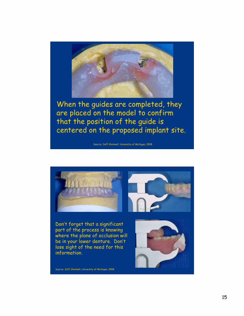
When the guides are completed, theyare placed on the model to confirmthat the position of the guide iscentered on the proposed implant site.
Source: Jeff Shotwell, University of Michigan, 2008
Don’t forget that a significantpart of the process is knowingwhere the plane of occlusion willbe in your lower denture. Don’tlose sight of the need for thisinformation.
Source: Jeff Shotwell, University of Michigan, 2008

16
The two surgical guides on the left were made by inserting the drill blanks inthe surveyor as any surveyor tool would be placed. The guide on the right usedthe clamp to hold the 3.5mm drill blank.
The guides are delivered to the surgeon who places the implants. Three monthslater having followed the patient and placed soft liner in the lower denture overand around the implant healing caps we are ready for the next phase of ourtreatment with the patient
Source: Jeff Shotwell, University of Michigan, 2008
Using the surgical guides gives us two implants placed inthe area of the lateral incisors. The implants areproperly spaced and oriented parallel with one another.
Source: Jeff Shotwell, University of Michigan, 2008

17
The cover screws placed at the time of surgery areremoved with a screwdriver designed specifically forthe purpose. This procedure is performed threemonths following the placement of the implants.
Source: Jeff Shotwell, University of Michigan, 2008
The driver for the retentiveanchor is triangular at theend. This driver fits into thetop of the retentive anchorcircled in the image at theleft.
Source: Jeff Shotwell, University of Michigan, 2008

18
The driver is placed in a torque wrench to place theretentive anchor in the implant at a specified torquesetting specifiec by the manufacturer. The specifiedtorque is such that the anchor will not come loose infunction.
The torque is specified by the deflectionof this flexible shaft and read byalignment with marks on the short arm offthe main body of the driver.
Source: Jeff Shotwell, University of Michigan, 2008
Torque driver components
Abutment being tightened to35Ncm
Source: Jeff Shotwell, University of Michigan, 2008

19
The deflection of the flexibleshaft is seen close up. We must“flex” the torque indicator to thethird mark indicating 35Ncm oftorque applied to the abutment.
Source: Jeff Shotwell, University of Michigan, 2008
The retentive anchorsonce placed will be used toretain the denture. Thelower image is an occlusalview showing thealignment of the retentiveanchors and the implants.
Source: Jeff Shotwell, University of Michigan, 2008

20
The silver colored cap is theretainer housing for polymerinserts which provide retentionfor the denture. The stainlesssteel cap is secured in thedenture using self cure acrylic.
Source: Jeff Shotwell, University of Michigan, 2008
The inner aspect of the lower denture is relieved toallow a passive fit over the retentive anchors. Thedenture is tried in the patient’s mouth to ensure apassive fit. The retentive caps will then be “picked up”in the mouth using self cure acrylic.
Source: Jeff Shotwell, University of Michigan, 2008

21
When the self cure acrylic is placed in therecesses in the denture, allow it to get a little“stiff” (it looses it’s gloss) and then place it in themouth and have the patient close in MIP holdingfor approximately 5 minutes.
Source: Jeff Shotwell, University of Michigan, 2008
The black colored insert is used to position thestainless steel cap on the retentive anchors for thepurpose of “pick up” in the denture. The image at theright shows the retentive anchors in place in thedenture. The other inserts shown at the left providediffering amounts of retention. The white neoprenegasket shown at the left protects from having theself cure acrylic “lock on” the implant / abutment inthe mouth.
Source: Jeff Shotwell, University of Michigan, 2008

22
The patient withthe retentiveanchors placed inthe denture.
Source: Jeff Shotwell, University of Michigan, 2008
Patient #2
Upper Partial Denture
Lower Arch Down To Last ToothWhich Needs To Be Extracted
Choices?
Conventional Denture
Implant Retained Overdenture
Source: Jeff Shotwell, University of Michigan, 2008

23
The images at the right showthe clinical appearance of theridge with the last remainingtooth.
The next two images show acast of the lower arch withthe tooth removed and drillguides placed in the proposedplacement sites of the twoimplants. Note that theguides are parallel to oneanother and perpendicular tothe plane of occlusion.
Source: Jeff Shotwell, University of Michigan, 2008
A surgical guide is fabricatedfrom self curing acrylic orTriad® material. The drillguide surrounds the lingualhalf of the drill. This allowsthe surgeon easy access duringsurgery for visibility as well asirrigation. The images shownhere do not yet have thematerial adapted to the lingualhalf of the drill guides.
Source: Jeff Shotwell, University of Michigan, 2008

24
The surgical images seen at theright show the implant sitesfirst with the depth guides inplace at the top image.
The center image shows theimplants in place with theirhealing screws in place.
The bottom image shows thesurgical site just prior toclosure with bone graft materialin place around the defect atthe labial of the implant in thearea of #27.
Source: Jeff Shotwell, University of Michigan, 2008
The ridge after closure and after a week to 10 days ofhealing. The lower temporary denture was relined withtru-soft temporary liner at that time.
Source: Jeff Shotwell, University of Michigan, 2008

25
The image above shows thepatient after two weeks ofhealling. The images at theright show the patient’s ridgeafter three months of healing.The retentive anchors will nowbe placed in the implants.
Source: Jeff Shotwell, University of Michigan, 2008
The image at the right shows a temporary denturerelined with fresh tru-soft around the implantretentive anchors. The denture at the right isn’t fromthe same patient as the image at the left, but thetreatment was the same.
Source: Jeff Shotwell, University of Michigan, 2008

26
The completed denture along with the temporarydenture are shown in the left image. The new denturein place shows the posterior teeth set in cross-bite.
Source: Jeff Shotwell, University of Michigan, 2008
Close up image of the retentive caps in the completeddenture. Note the polymer rings in place around the goldretentive cylinders. The image at the right showsadjusting tools for the retentive clips.
Source: Jeff Shotwell, University of Michigan, 2008

27
The initial height ofthe implants createda situation in whichthere was minimalacrylic covering theretentive caps in thefinished denture.
At the time of implant placement, if more of theresidual ridge had been reduced we would not have thesituation seen above. This minimal acrylic coverage ofthe retentive anchors causes maintenance issues.
You can see that we have little acrylic over theretentive anchor caps especially on the patient’sright side.
Source: Jeff Shotwell,
University of Michigan, 2008
A brief review of the steps taken to treat the patient.
Source: Jeff Shotwell, University of Michigan, 2008


![Comparison of clinical and radiographic status around ...fac.ksu.edu.sa/sites/default/files/17._comparison_of_clinical.pdf · [T2DM]) is a significant risk factor for peri-implant](https://img.dokumen.tips/doc/110x75/5f0c05277e708231d4335bcc/comparison-of-clinical-and-radiographic-status-around-facksuedusasitesdefaultfiles17comparisonof.jpg)