Embed Size (px)
Citation preview
Review ArticleFriction Welding of Aluminium and AluminiumAlloys with Steel
Andrzej Ambroziak, Marcin Korzeniowski, PaweB KustroN, Marcin Winnicki,PaweB SokoBowski, and Ewa HarapiNska
Welding Technology Department, Institute of Production Engineering and Automation,Wroclaw University of Technology, 50-370 Wroclaw, Poland
Correspondence should be addressed to Andrzej Ambroziak; [email protected]
Received 10 December 2013; Revised 12 February 2014; Accepted 11 March 2014; Published 28 April 2014
Academic Editor: Achilles Vairis
Copyright © 2014 Andrzej Ambroziak et al. This is an open access article distributed under the Creative Commons AttributionLicense, which permits unrestricted use, distribution, and reproduction in any medium, provided the original work is properlycited.
The paper presents our actual knowledge and experience in joining dissimilar materials with the use of friction welding method.The joints of aluminium and aluminium alloys with the different types of steel were studied.The structural effects occurring duringthe welding process were described. The mechanical properties using, for example, (i) microhardness measurements, (ii) tensiletests, (iii) bending tests, and (iv) shearing tests were determined. In order to obtain high-quality joints the influence of differentconfigurations of the process such as (i) changing the geometry of bonding surface, (ii) using the interlayer, or (iii) heat treatmentwas analyzed. Finally, the issues related to the selection of optimal parameters of friction welding process were also investigated.
1. Introduction
The family of friction welding processes includes severalmethods, such as rotary friction welding (RFW), linearfriction welding (LFW), and the newest one, friction stirwelding (FSW). However, the main principle is always thesame—to obtain the joint it is necessary to heat the materialsto the plastic-state and with the use of “upsetting force”plastically displace thematerials and create the weld.The heatis generated by the friction between two welded components(RFW and LFW) or between components and speciallydesigned tool (FSW). Welding processes are classified assolid-state joining methods because the melting of joinedmaterials does not occur these processes [1–3].
A big attractiveness of these joining methods resultsfrom many technical and economic advantages, such as highefficiency and stability of the process or better conditions ofoccupational safety and health than in the case of traditionalwelding technologies. However, recently, the most importantseems to be the possibility of joining materials with differentproperties. Due to the fact that in the fusion zone betweenthe two different materials the intermetallic compounds areformed and the joining process of dissimilar materials is
often very difficult. To obtain high-quality joint it is necessaryto know and analyze phase diagram of the two weldedmaterials. Furthermore, the microstructure and differentproperties of intermetallic phases, such as crack sensitivity,ductility, and corrosion resistance,, are also very important.There are some additional factors, for example, coefficientsof thermal expansion of welded materials and their meltingtemperatures, the knowledge of which is also necessary in thecase of joining dissimilar materials [3–6].
The presented review summarizes our actual knowledgeabout the friction welding of aluminium and aluminiumalloys with different types of steel. This paper describes bothauthors’ research as well as many other studies of scientistsdealing with the presented subject.
2. Results and Discussion
2.1. Aluminium-Steel. Joining with the welding methods ofthe pairs of materials, such as aluminium alloys-steel, stillbrings many problems. Even the analysis of the aluminium-iron dual system leads to the conclusion that sufficientlylong time and high temperatures of the process can cause
Hindawi Publishing CorporationAdvances in Materials Science and EngineeringVolume 2014, Article ID 981653, 15 pageshttp://dx.doi.org/10.1155/2014/981653
2 Advances in Materials Science and Engineering
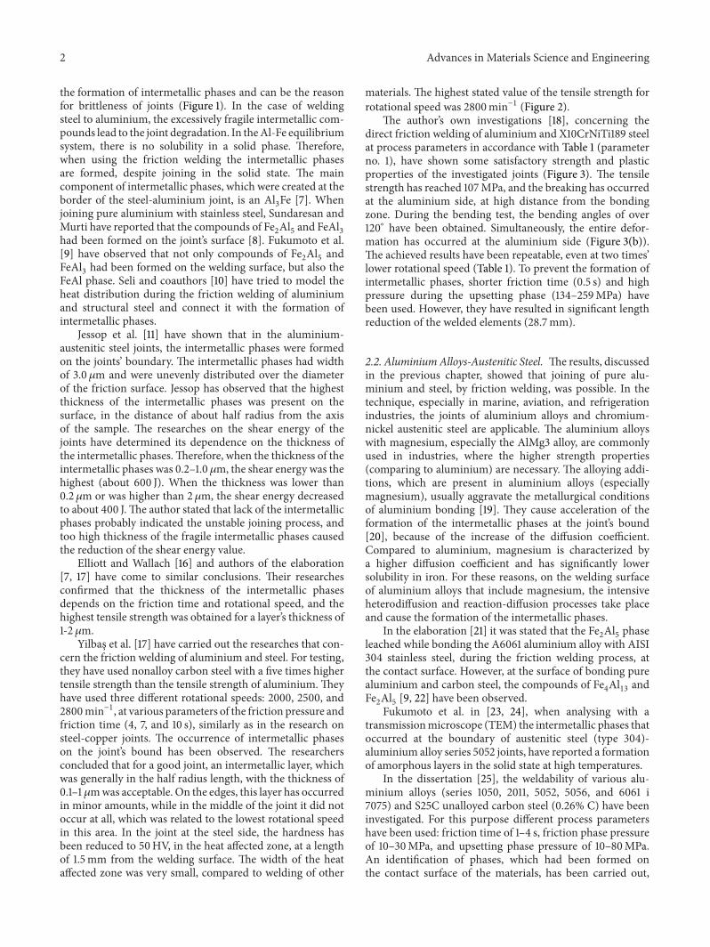
the formation of intermetallic phases and can be the reasonfor brittleness of joints (Figure 1). In the case of weldingsteel to aluminium, the excessively fragile intermetallic com-pounds lead to the joint degradation. In theAl-Fe equilibriumsystem, there is no solubility in a solid phase. Therefore,when using the friction welding the intermetallic phasesare formed, despite joining in the solid state. The maincomponent of intermetallic phases, which were created at theborder of the steel-aluminium joint, is an Al
3Fe [7]. When
joining pure aluminium with stainless steel, Sundaresan andMurti have reported that the compounds of Fe
2Al5and FeAl
3
had been formed on the joint’s surface [8]. Fukumoto et al.[9] have observed that not only compounds of Fe
2Al5and
FeAl3had been formed on the welding surface, but also the
FeAl phase. Seli and coauthors [10] have tried to model theheat distribution during the friction welding of aluminiumand structural steel and connect it with the formation ofintermetallic phases.
Jessop et al. [11] have shown that in the aluminium-austenitic steel joints, the intermetallic phases were formedon the joints’ boundary. The intermetallic phases had widthof 3.0 𝜇m and were unevenly distributed over the diameterof the friction surface. Jessop has observed that the highestthickness of the intermetallic phases was present on thesurface, in the distance of about half radius from the axisof the sample. The researches on the shear energy of thejoints have determined its dependence on the thickness ofthe intermetallic phases.Therefore, when the thickness of theintermetallic phases was 0.2–1.0 𝜇m, the shear energy was thehighest (about 600 J). When the thickness was lower than0.2 𝜇m or was higher than 2 𝜇m, the shear energy decreasedto about 400 J.The author stated that lack of the intermetallicphases probably indicated the unstable joining process, andtoo high thickness of the fragile intermetallic phases causedthe reduction of the shear energy value.
Elliott and Wallach [16] and authors of the elaboration[7, 17] have come to similar conclusions. Their researchesconfirmed that the thickness of the intermetallic phasesdepends on the friction time and rotational speed, and thehighest tensile strength was obtained for a layer’s thickness of1-2 𝜇m.
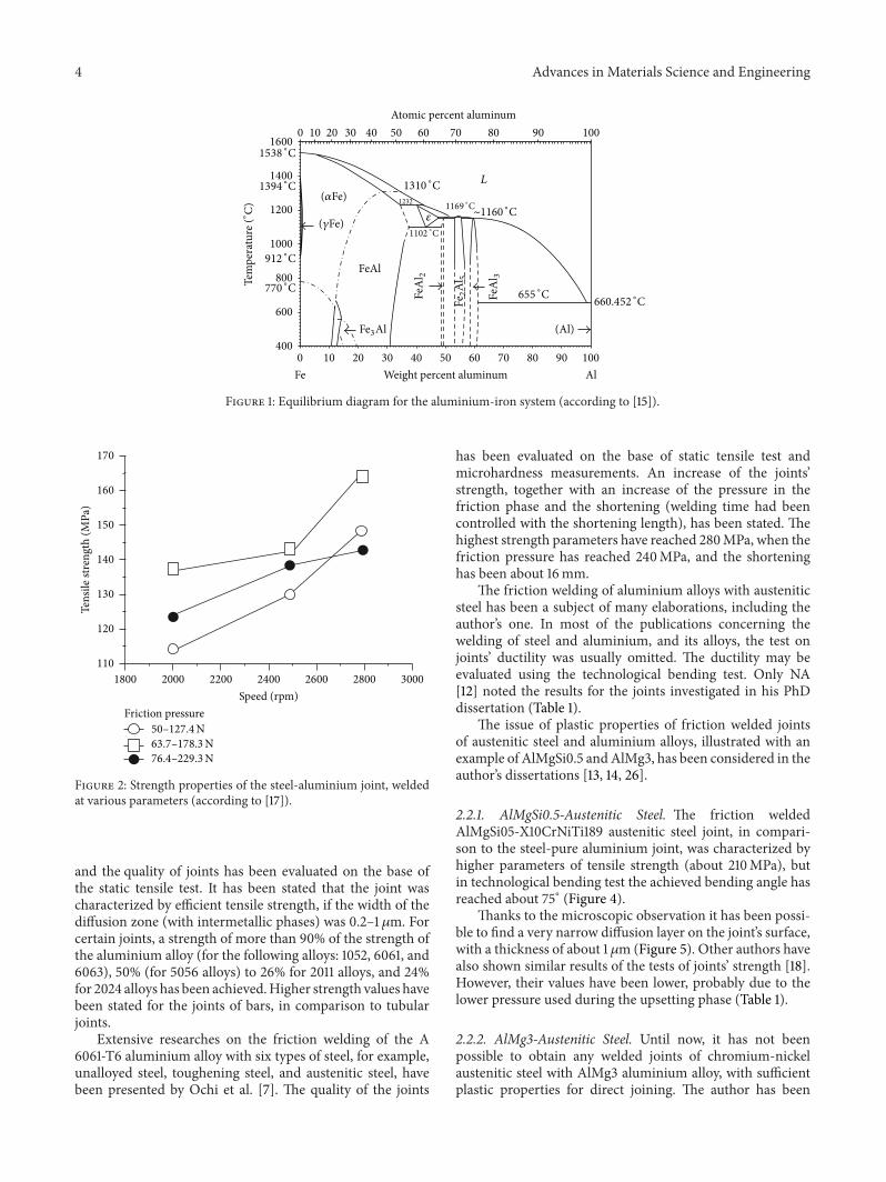
Yilbas et al. [17] have carried out the researches that con-cern the friction welding of aluminium and steel. For testing,they have used nonalloy carbon steel with a five times highertensile strength than the tensile strength of aluminium.Theyhave used three different rotational speeds: 2000, 2500, and2800min−1, at various parameters of the friction pressure andfriction time (4, 7, and 10 s), similarly as in the research onsteel-copper joints. The occurrence of intermetallic phaseson the joint’s bound has been observed. The researchersconcluded that for a good joint, an intermetallic layer, whichwas generally in the half radius length, with the thickness of0.1–1 𝜇mwas acceptable. On the edges, this layer has occurredin minor amounts, while in the middle of the joint it did notoccur at all, which was related to the lowest rotational speedin this area. In the joint at the steel side, the hardness hasbeen reduced to 50HV, in the heat affected zone, at a lengthof 1.5mm from the welding surface. The width of the heataffected zone was very small, compared to welding of other
materials. The highest stated value of the tensile strength forrotational speed was 2800min−1 (Figure 2).
The author’s own investigations [18], concerning thedirect friction welding of aluminium and X10CrNiTi189 steelat process parameters in accordance with Table 1 (parameterno. 1), have shown some satisfactory strength and plasticproperties of the investigated joints (Figure 3). The tensilestrength has reached 107MPa, and the breaking has occurredat the aluminium side, at high distance from the bondingzone. During the bending test, the bending angles of over120∘ have been obtained. Simultaneously, the entire defor-mation has occurred at the aluminium side (Figure 3(b)).The achieved results have been repeatable, even at two times’lower rotational speed (Table 1). To prevent the formation ofintermetallic phases, shorter friction time (0.5 s) and highpressure during the upsetting phase (134–259MPa) havebeen used. However, they have resulted in significant lengthreduction of the welded elements (28.7mm).
2.2. AluminiumAlloys-Austenitic Steel. The results, discussedin the previous chapter, showed that joining of pure alu-minium and steel, by friction welding, was possible. In thetechnique, especially in marine, aviation, and refrigerationindustries, the joints of aluminium alloys and chromium-nickel austenitic steel are applicable. The aluminium alloyswith magnesium, especially the AlMg3 alloy, are commonlyused in industries, where the higher strength properties(comparing to aluminium) are necessary. The alloying addi-tions, which are present in aluminium alloys (especiallymagnesium), usually aggravate the metallurgical conditionsof aluminium bonding [19]. They cause acceleration of theformation of the intermetallic phases at the joint’s bound[20], because of the increase of the diffusion coefficient.Compared to aluminium, magnesium is characterized bya higher diffusion coefficient and has significantly lowersolubility in iron. For these reasons, on the welding surfaceof aluminium alloys that include magnesium, the intensiveheterodiffusion and reaction-diffusion processes take placeand cause the formation of the intermetallic phases.
In the elaboration [21] it was stated that the Fe2Al5phase
leached while bonding the A6061 aluminium alloy with AISI304 stainless steel, during the friction welding process, atthe contact surface. However, at the surface of bonding purealuminium and carbon steel, the compounds of Fe
4Al13and
Fe2Al5[9, 22] have been observed.
Fukumoto et al. in [23, 24], when analysing with atransmissionmicroscope (TEM) the intermetallic phases thatoccurred at the boundary of austenitic steel (type 304)-aluminium alloy series 5052 joints, have reported a formationof amorphous layers in the solid state at high temperatures.
In the dissertation [25], the weldability of various alu-minium alloys (series 1050, 2011, 5052, 5056, and 6061 i7075) and S25C unalloyed carbon steel (0.26% C) have beeninvestigated. For this purpose different process parametershave been used: friction time of 1–4 s, friction phase pressureof 10–30MPa, and upsetting phase pressure of 10–80MPa.An identification of phases, which had been formed onthe contact surface of the materials, has been carried out,

Advances in Materials Science and Engineering 3Ta
ble1:Th
eparam
eterso
ffric
tionwelding
andstreng
thprop
ertie
sofjointso
fdiss
imilarm
aterials(aluminium
andalum
inium
alloys
with
steelor
titanium).
No.
Weld
edmaterials
Rotatio
nal
speed
[min−1]
Frictio
npressure
(sho
rteningspeed)
𝑝𝑡1/𝑝𝑡2[M
Pa]
(V𝑅,m
ms−1)
Frictio
ntim
e𝑡 𝑡1/𝑡 𝑡2[s]
Upsettin
gpressure
𝑝𝑠[M
Pa]
Shortening𝑠𝑡/𝑠[m
m]
Tensile
strength
𝑅𝑚[M
Pa]
Bend
ingangle
(toug
hness)
[∘](Jc
m2 )
Com
ments
Literature
1Au
stenitic
steel-aluminium
1300
41.5
233.4
[11]
1500
750.5
134/259
4.5/28.7
107
Over120
MR(A
l)incl.
26/77
1.5/0.2
235
3.8/39
78MR(A
l)710
770.65
131
4.7/19.5
incl.
2Au
stenitic
steel-Al0.5Si
0.5M
galloy
1500
52/94
1.5/0.2
235
7.2/25.1
210
75incl.
1300
9.01.0
254.0
Tapered
surfa
ceof
steel
[11]
1500
(1.0)
4.3
100
14.6
160
52[12]
12.7
169
51Tapered
surfa
ceof
steel
[12]
3Au
stenitic
steel-AlM
g3alloy
1500
(1.0)
4.8
858.1
113
1.5[12]
120
13.0
197
1.3Tapered
surfa
ceof
steel
[12]
69/92
2/0.2
300
1.6/20.5
7[13]
85/96
1/0.3
239
1.2/13
.7207
11AlM
g3[13]
43/12
04/0.5
239
15/23
197
13Scratcheso
nthes
urface
[13]
710
832.4/1.2
256
0.8/17
9[13]
382.4/60
256
0.3/21.7
0[13]
4Au
stenitic
steel/aluminium-AlM
g3alloy∗
1500
24/28
3/03
811.6
/14.1
90
Over120
Al-3
5mm
[13]
107
Al-2
5mm
[13]
128
Al-8
mm
[13]
185
Al-3
mm
[13]
5AlCuM
gNi-4
2CrM
o4
720
104/121
1.0/0.2
300
0.6/4
98[14
]1500
107/124
1.0/0.2
200
0.5/2.9
102
[14]
720
41/96
4.0/0.9
160
3.5/4.2
114[14
]1500
41/96
4.0/0.85
160
5.6/7.4
54[14
]720
41/96
4.0/0.85
160
5.6/7.4
54[14
]720(D
1)41/93
4.0/0.9
161
3.2/4.1
198
[14]
720(D
2)41/90
4.0/0.85
161
3.4/4.6
0[14
]6
42Cr
Mo4
-nickel
720
24/55
2.0/18.35
811.1/2.0
[14]
742Cr
Mo4
/nickel-
AlCuM
gNi∗
720
41/92
4.0/0.9
161
4.4/5.1
211
[14]
720
41/10
34.0/0.85
200
6.8/9.8
235
[14]
720(R)
41/12
24.0/0.9
242
9.7/13
.6265
[14]
720(RW)
41/114
4.0/0.9
223
5.9/9.5
272
[14]
8AlM
g3-titanium
1500
69/91
2.4/0.2
200
3.2/11.6
205.4
120
[13]
9Al.-AlM
g31500
243.03
802.4/18.1
72120
MRAl
[13]
10AlM
gSi0.5-AlM
g31500
52/94
1.5/0.2
235
7.2/25.1
210
75MRAl
incl.
35/40
3/0.3
120/134
3.2/17.6
210
120
MRAl
incl.
Upsettin
gtim
e(𝑡𝑠1,𝑡𝑠2)=
10s
D—jointsadditio
nally
subjectedto
diffu
sionweld
ingat
parameters:1—
5000∘C,
2min,and
pressure
5MPa;2—550∘C,
40min,and
pressure
5MPa;R
—nickelsurfa
cewith
high
roug
hnessp
aram
eters;W—joint
subjectedto
heat
treatment(680∘C,
1h,vacuu
moven);incl.—ow
ninvestigatio
ns;M
R(A
l)—du
ringthetensile
testthebreaking
ofthespecim
enhaso
ccurredat
thealum
inium
side;∗—3-Tweld
ing,
where
“/”
means
firstweld
edmaterialand
“—”m
eans
second
weldedmaterial.
4 Advances in Materials Science and Engineering
100 20 30 40 50 60 70 80 90 100
Weight percent aluminum
(Al)
AlFe
Atomic percent aluminum
(𝛼Fe)
(𝛾Fe)
FeAl
Fe3Al
FeA
l 2
Fe2A
l 5
FeA
l 3
1538 ∘C
1394 ∘C
912 ∘C
770 ∘C
1310 ∘C
1102 ∘C
1169 ∘C
655 ∘C660.452 ∘C
𝜀
1232
L
100 20 30 40 50 60 70 80 90 1001600
1400
1200
1000
800
600
400
Tem
pera
ture
(∘C) ∼1160 ∘C
Figure 1: Equilibrium diagram for the aluminium-iron system (according to [15]).
170
160
150
140
130
120
110
Tens
ile st
reng
th (M
Pa)
Friction pressureSpeed (rpm)
1800 2000 2200 2400 2600 2800 3000
50–127.4N63.7–178.3N76.4–229.3N
Figure 2: Strength properties of the steel-aluminium joint, weldedat various parameters (according to [17]).
and the quality of joints has been evaluated on the base ofthe static tensile test. It has been stated that the joint wascharacterized by efficient tensile strength, if the width of thediffusion zone (with intermetallic phases) was 0.2–1 𝜇m. Forcertain joints, a strength of more than 90% of the strength ofthe aluminium alloy (for the following alloys: 1052, 6061, and6063), 50% (for 5056 alloys) to 26% for 2011 alloys, and 24%for 2024 alloys has been achieved.Higher strength values havebeen stated for the joints of bars, in comparison to tubularjoints.
Extensive researches on the friction welding of the A6061-T6 aluminium alloy with six types of steel, for example,unalloyed steel, toughening steel, and austenitic steel, havebeen presented by Ochi et al. [7]. The quality of the joints
has been evaluated on the base of static tensile test andmicrohardness measurements. An increase of the joints’strength, together with an increase of the pressure in thefriction phase and the shortening (welding time had beencontrolled with the shortening length), has been stated. Thehighest strength parameters have reached 280MPa, when thefriction pressure has reached 240MPa, and the shorteninghas been about 16mm.
The friction welding of aluminium alloys with austeniticsteel has been a subject of many elaborations, including theauthor’s one. In most of the publications concerning thewelding of steel and aluminium, and its alloys, the test onjoints’ ductility was usually omitted. The ductility may beevaluated using the technological bending test. Only NA[12] noted the results for the joints investigated in his PhDdissertation (Table 1).
The issue of plastic properties of friction welded jointsof austenitic steel and aluminium alloys, illustrated with anexample of AlMgSi0.5 andAlMg3, has been considered in theauthor’s dissertations [13, 14, 26].
2.2.1. AlMgSi0.5-Austenitic Steel. The friction weldedAlMgSi05-X10CrNiTi189 austenitic steel joint, in compari-son to the steel-pure aluminium joint, was characterized byhigher parameters of tensile strength (about 210MPa), butin technological bending test the achieved bending angle hasreached about 75∘ (Figure 4).
Thanks to the microscopic observation it has been possi-ble to find a very narrow diffusion layer on the joint’s surface,with a thickness of about 1𝜇m (Figure 5). Other authors havealso shown similar results of the tests of joints’ strength [18].However, their values have been lower, probably due to thelower pressure used during the upsetting phase (Table 1).
2.2.2. AlMg3-Austenitic Steel. Until now, it has not beenpossible to obtain any welded joints of chromium-nickelaustenitic steel with AlMg3 aluminium alloy, with sufficientplastic properties for direct joining. The author has been

Advances in Materials Science and Engineering 5
Weld line
(a) (b)
Figure 3: View of friction welded joints of 99.8 aluminium-X10CrNiTi189 austenitic steel, after the static tensile test (a) and the technologicalbending test (b).
Weld line
(a) (b)
Figure 4: View of friction welded joints of AlMgSi0.5 aluminium alloy-X10CrNiTi189 austenitic steel, after the static tensile test (a) and thetechnological bending test (b).
Figure 5: The microstructure in the bonding zone of the frictionwelded AlMgSi0.5 aluminium alloy-X10CrNiTi189 austenitic steeljoint (according to [13]).
conducting some intensive researches on the friction weldingof such joints, partly presented in [13].
The friction welded joints of AlMg3-X10CrNiTi189 steelwith diameter of 30mm had high tensile strength (about207MPa), and the fracture occurred in the base materialof AlMg3 alloy (Figure 6(a)). However, in the technologicalbending tests, bending angles within few degrees have beenachieved, with a small dependence on the diameter of thebending mandrel.
The metallographic researches have shown the appear-ance of the diffusion zone with diameter of 1–6𝜇m, depend-ing on the welding parameters. Despite the short time
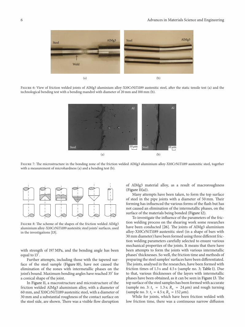
of the welding process and the high pressure during theupsetting (sample no. 3; Table 1), it has not been possibleto fully remove the intermetallic phases from the joint’ssurface. For the research purposes, a friction welding fora pair of AlMg3 aluminium alloy-X10CrNiTi189 austeniticsteel has been conducted, at high welding time (about 62 s).In such joint a wide (about 8 𝜇m) diffusion zone, withmicrohardness reaching up to 1800HV 0.005, has appeared(Figure 7(a)). On the steel side, the microhardness has beenequal to 83HV 0.005, and at the intermetallic phases layerit has reached 348HV 0.005. Therefore, at the aluminiumalloy side, in a zone adjacent to the intermetallic phases,the increase of microhardness (up to 65HV 0.005) has beenreported (microhardness of base material is 58HV 0.005).The technological bending test of such joint has ended withan immediate crack which has passed the intermetallic layers(Figure 7(b)).
At short welding time (𝑡𝑡= 3.6 s) the width of the
intermetallic phases has reached 1-2 𝜇m, but the bendingangle has been about 10∘. Several attempts to eliminate theintermetallic phases by changing the geometry of bond’ssurface have been taken (Figure 8).
Figure 9 presents the microstructure of the bonding zoneof the frictionwelded AlMg3 aluminium alloy-X10CrNiTi189austenitic steel joint, together with a microhardness mea-surement. The front surface of the steel sample has beenprepared with a rough turning (roughness of 𝑅
𝑧= 150 𝜇m).
In Figure 9(a), on the aluminium alloy side, there was a zonewith a diameter of 500𝜇m, without any microinclusions, andwith an increased microhardness, up to 74HV 0.015 (basematerial: 64HV 0.015). On the boundary of the joint, therewas a narrow (about 1 𝜇m) diffusion zone. The static tensiletest has caused a fracture of a sample, on the contact surface,
6 Advances in Materials Science and Engineering
Weld
SteelAlMg3
(a)
Steel AlMg3
(b)
Figure 6: View of friction welded joints of AlMg3 aluminium alloy-X10CrNiTi189 austenitic steel, after the static tensile test (a) and thetechnological bending test with a bending mandrel with diameter of 20mm and 100mm (b).
Steel
Al
10𝜇m
(a)
Steel
Al
10𝜇m
(b)
Figure 7: The microstructure in the bonding zone of the friction welded AlMg3 aluminium alloy-X10CrNiTi189 austenitic steel, togetherwith a measurement of microhardness (a) and a bending test (b).
Figure 8: The scheme of the shapes of the friction welded AlMg3aluminium alloy-X10CrNiTi189 austenitic steel joints’ surfaces, usedin the investigations [13].
with strength of 197MPa, and the bending angle has beenequal to 13∘.
Further attempts, including those with the tapered sur-face of the steel sample (Figure 10), have not caused theelimination of the zones with intermetallic phases on thejoint’s bound. Maximum bending angles have reached 35∘ fora conical shape of the joint.
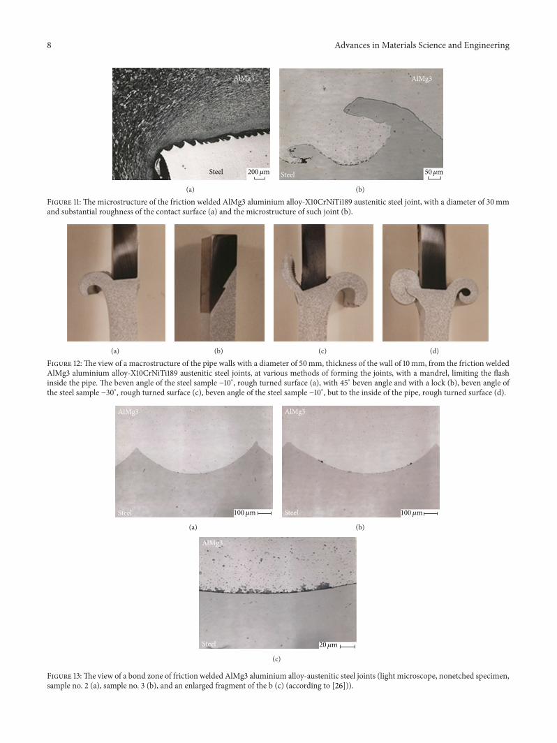
In Figure 11, a macrostructure and microstructure of thefriction welded AlMg3 aluminium alloy, with a diameter of60mm, and X10CrNiTi189 austenitic steel, with a diameter of30mm and a substantial roughness of the contact surface onthe steel side, are shown. There was a visible flow disruption
of AlMg3 material alloy, as a result of macroroughness(Figure 11(a)).
Many attempts have been taken, to form the top surfaceof steel in the pipe joints with a diameter of 50mm. Theirforming has influenced the various forms of the flash but hasnot caused an elimination of the intermetallic phases, on thesurface of the materials being bonded (Figure 12).
To investigate the influence of the parameters of the fric-tion welding process on the shearing work some researcheshave been conducted [26]. The joints of AlMg3 aluminiumalloy-X10CrNiTi189 austenitic steel (in a shape of bars with30mmdiameter) have been formed using three different fric-tion welding parameters carefully selected to ensure variousmechanical properties of the joints. It means that there havebeen attempts to form the joints with various intermetallicphases’ thicknesses. So well, the friction time andmethods ofpreparing the steel samples’ surfaces have been differentiated.The joints, analysed in the researches, have been formed withfriction times of 1.3 s and 4.5 s (sample no. 3; Table 1). Dueto that, various thicknesses of the layers with intermetallicphases have been obtained, as it can be seen in Figure 13. Thetop surface of the steel samples has been formedwith accurate(sample no. 3: 𝑡
𝑡= 1.3 s; 𝑅
𝑧= 24 𝜇m) and rough turning
(sample no. 3: 𝑡𝑡= 4.5 s; 𝑅
𝑧= 152 𝜇m).
While for joints, which have been friction welded withlow friction time, there was a continuous narrow diffusion

Advances in Materials Science and Engineering 7
SteelAl64
HV0.015
68
HV0.015
71
HV0.015
74
HV0.015
100 𝜇m
(a)
Al Steel
15𝜇m
(b)
Figure 9:Themicrostructure in the bonding zone of the friction welded AlMg3 aluminium alloy-X10CrNiTi189 austenitic steel (steel samplewith a rough surface of 𝑅
𝑧= 150 𝜇m) (a) and an enlarged fragment of the microstructure from Figure 9(a) (b).
Steel
AlMg3
10mm
(a)
AlMg3
Steel20𝜇m
(b)
Figure 10:The macrostructure of the friction welded AlMg3 aluminium alloy-X10CrNiTi189 austenitic steel joint, with a diameter of 30mmand a conical shape of the joint (a) and the microstructure of such joint (b).
zone with a diameter of few micrometers (Figure 13(a)); thejoints formed at longer friction time were characterized bylocal thickening of the diffusion layer and discontinuities onthe aluminium side (Figures 13(b) and 13(c)).
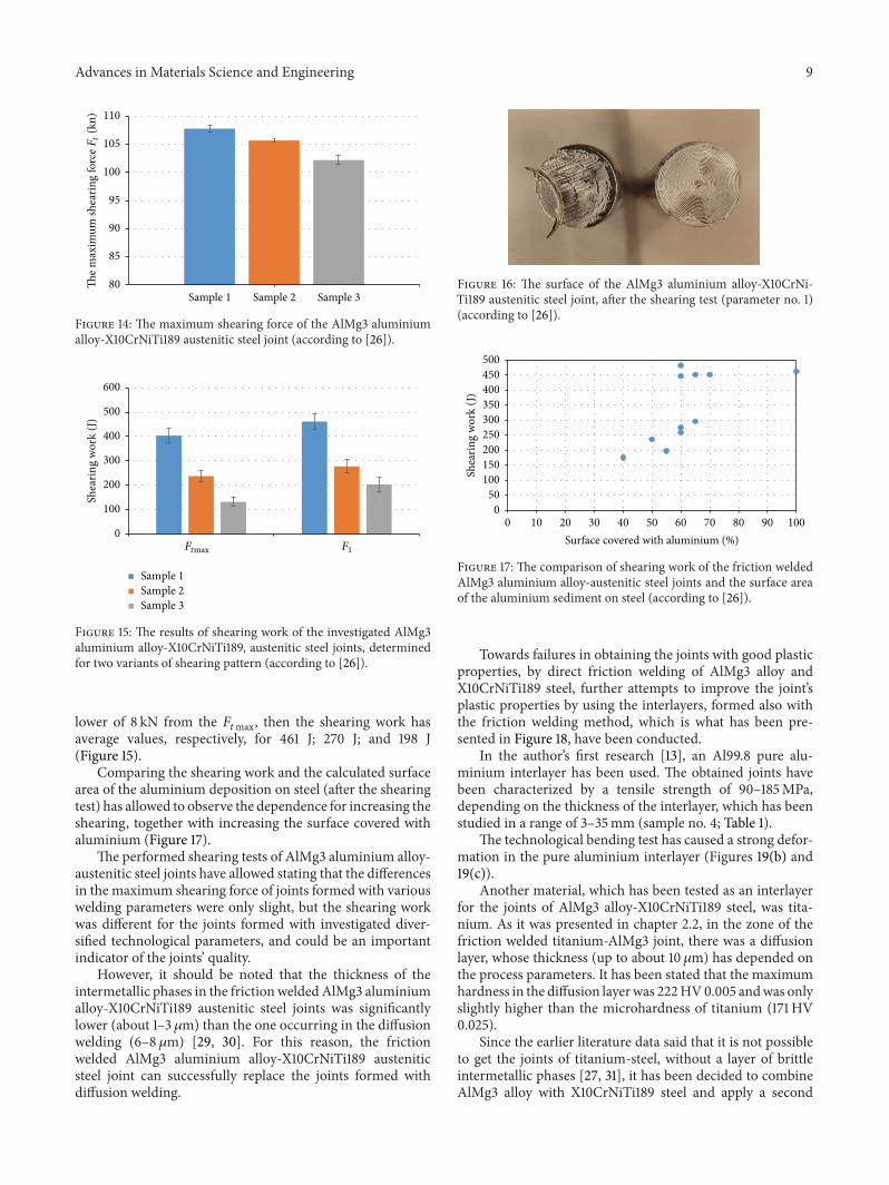
The results of the maximum loading force, obtained inthe shearing test for the investigated joints, are shown inFigure 14, whereas, in Figure 15, the results of shearing work,calculated for two variants of shearing patterns, 𝐹
𝑡max and 𝐹1,are shown. The samples after the shearing test are presentedin Figure 16. In the cross-section, depending on the weldingparameters, a precipitate of aluminium on the steel side withthe amount from 0 to 100% of the sample’s surface, dependingon the welding parameters, was visible.
From the previous researches [27, 28] it was known thatduring the friction welding of steel, including austenitic steelwith aluminium alloys (with over 2% of magnesium), theformation of hard and fragile intermetallic phases of Al
13Fe4
type has occurred. Their formation has depended on thediffusion processes that were accelerated by magnesium andtheir thickness has depended on the welding parameters(especially on the friction time). The joints, analysed in theresearches, have been formed with two different friction
time parameters, so various thicknesses of the layers withintermetallic phases have occurred. So, for joints that havebeen friction welded with low friction time, there was acontinuous narrow diffusion zone with a diameter of fewmicrometers (Figure 13(a)) and the joints formed at longerfriction time were characterized by local thickening of thediffusion layer and discontinuities on the aluminium side(Figures 13(b) and 13(c)). However, the shearing test hasproven a difference of about 5%, for the maximum shearingforce between the joints formedwith the investigated weldingparameters (Figure 14). Wherein, the highest values (averageof 107.8 kN) have been stated for the samples welded at lowfriction phase time, and the lowest (102.2 kN) values havebeen obtained for the samples welded at high friction phasetime. Therefore, the measurements of the shearing work,carried out for various stages of the test, have shown thatthere were huge shearing work differences for the analysedjoints, and they have depended on the process parameters.If the period to the highest shearing force value 𝐹
𝑡max wasanalysed, then the shearing work was, respectively, for thewelding parameters 402 J; 245 J; and 132 J (Figure 15). Whenconsidering the period for the force 𝐹
1, that is, for a force
8 Advances in Materials Science and Engineering
AlMg3
Steel 200𝜇m
(a)
AlMg3
Steel 50𝜇m
(b)
Figure 11: The microstructure of the friction welded AlMg3 aluminium alloy-X10CrNiTi189 austenitic steel joint, with a diameter of 30mmand substantial roughness of the contact surface (a) and the microstructure of such joint (b).
(a) (b) (c) (d)
Figure 12:The view of a macrostructure of the pipe walls with a diameter of 50mm, thickness of the wall of 10mm, from the friction weldedAlMg3 aluminium alloy-X10CrNiTi189 austenitic steel joints, at various methods of forming the joints, with a mandrel, limiting the flashinside the pipe. The beven angle of the steel sample −10∘, rough turned surface (a), with 45∘ beven angle and with a lock (b), beven angle ofthe steel sample −30∘, rough turned surface (c), beven angle of the steel sample −10∘, but to the inside of the pipe, rough turned surface (d).
AlMg3
Steel 100𝜇m
(a)
AlMg3
Steel 100𝜇m
(b)
AlMg3
Steel 20𝜇m
(c)
Figure 13:The view of a bond zone of friction welded AlMg3 aluminium alloy-austenitic steel joints (light microscope, nonetched specimen,sample no. 2 (a), sample no. 3 (b), and an enlarged fragment of the b (c) (according to [26])).
Advances in Materials Science and Engineering 9
80
85
90
95
100
105
110
Sample 1 Sample 2 Sample 3
The m
axim
um sh
earin
g fo
rceF
t(k
n)
Figure 14: The maximum shearing force of the AlMg3 aluminiumalloy-X10CrNiTi189 austenitic steel joint (according to [26]).
0
100
200
300
400
500
600
Shea
ring
wor
k (J
)
Sample 1Sample 2Sample 3
F1Ftmax
Figure 15: The results of shearing work of the investigated AlMg3aluminium alloy-X10CrNiTi189, austenitic steel joints, determinedfor two variants of shearing pattern (according to [26]).
lower of 8 kN from the 𝐹𝑡max, then the shearing work has
average values, respectively, for 461 J; 270 J; and 198 J(Figure 15).
Comparing the shearing work and the calculated surfacearea of the aluminium deposition on steel (after the shearingtest) has allowed to observe the dependence for increasing theshearing, together with increasing the surface covered withaluminium (Figure 17).
The performed shearing tests of AlMg3 aluminium alloy-austenitic steel joints have allowed stating that the differencesin the maximum shearing force of joints formed with variouswelding parameters were only slight, but the shearing workwas different for the joints formed with investigated diver-sified technological parameters, and could be an importantindicator of the joints’ quality.
However, it should be noted that the thickness of theintermetallic phases in the frictionweldedAlMg3 aluminiumalloy-X10CrNiTi189 austenitic steel joints was significantlylower (about 1–3𝜇m) than the one occurring in the diffusionwelding (6–8𝜇m) [29, 30]. For this reason, the frictionwelded AlMg3 aluminium alloy-X10CrNiTi189 austeniticsteel joint can successfully replace the joints formed withdiffusion welding.
Figure 16: The surface of the AlMg3 aluminium alloy-X10CrNi-Ti189 austenitic steel joint, after the shearing test (parameter no. 1)(according to [26]).
050
100150200250300350400450500
0 10 20 30 40 50 60 70 80 90 100
Shea
ring
wor
k (J
)
Surface covered with aluminium (%)
Figure 17: The comparison of shearing work of the friction weldedAlMg3 aluminium alloy-austenitic steel joints and the surface areaof the aluminium sediment on steel (according to [26]).
Towards failures in obtaining the joints with good plasticproperties, by direct friction welding of AlMg3 alloy andX10CrNiTi189 steel, further attempts to improve the joint’splastic properties by using the interlayers, formed also withthe friction welding method, which is what has been pre-sented in Figure 18, have been conducted.
In the author’s first research [13], an Al99.8 pure alu-minium interlayer has been used. The obtained joints havebeen characterized by a tensile strength of 90–185MPa,depending on the thickness of the interlayer, which has beenstudied in a range of 3–35mm (sample no. 4; Table 1).
The technological bending test has caused a strong defor-mation in the pure aluminium interlayer (Figures 19(b) and19(c)).
Another material, which has been tested as an interlayerfor the joints of AlMg3 alloy-X10CrNiTi189 steel, was tita-nium. As it was presented in chapter 2.2, in the zone of thefriction welded titanium-AlMg3 joint, there was a diffusionlayer, whose thickness (up to about 10 𝜇m) has depended onthe process parameters. It has been stated that the maximumhardness in the diffusion layerwas 222HV0.005 andwas onlyslightly higher than the microhardness of titanium (171HV0.025).
Since the earlier literature data said that it is not possibleto get the joints of titanium-steel, without a layer of brittleintermetallic phases [27, 31], it has been decided to combineAlMg3 alloy with X10CrNiTi189 steel and apply a second

10 Advances in Materials Science and Engineering
AlMg3 AlMg3
AlMg3
AlMg3 Aluminium
AluminiumTitanium
Titanium
X10CrNiTi189
X10CrNiTi189
X10CrNiTi189
Figure 18: The scheme of forming the AlMg3 aluminium alloy-X10CrNiTi189 austenitic steel joint, with interlayers.
interlayer, that is, the layer between the steel and the titanium(Figure 18). For the material of this layer the pure Al99.8aluminium or the AlMg3 alloy has been used. When formingthe joints with pure aluminium, the tensile strength has beenequal to 185MPa, and the fracture has occurred at the boundof the aluminium-steel bond. The technological bending testhas proved the strong deformation at the aluminium layer.
Using the AlMg3 alloy, as a second layer, has allowed toobtain joints with a strength of 346MPa (the fracture at theAlMg3-steel bound) and to achieve the bending angle ofmorethan 120∘ in the technological bending test. Such behaviourmay be caused that despite forming the intermetallic phaseson the bound of AlMg3 alloy-X10CrNiTi189 steel, the lowthickness of the whole additional interlayer allowed stresstransfer occurring in the joint during bending.The deforma-tion was observed behind the titanium layer on the AlMg3side (Figure 20(c)).
Thus, using the titanium and AlMg3 interlayer in theAlMg3 alloy-X10CrNiTi189 austenitic steel joints has enabledto achieve a joint characterized by high strength and relativelyhigh bending angle.
2.2.3. CrMo4 Steel-AlCuMgNi Aluminium Alloy. In the dis-sertation [14], the author has presented part of the investiga-tions on the friction welding of the AlCuMgNi aluminiumalloy (according to ASTM B247), under the trade nameof AN40 as forgings in a T6 supply state (supersaturatedand then artificially aged), with steel for quenching andtempering, grade 42CrMo4 in the form of round bars witha diameter of 45mm. Using of such high diameters ofthe samples has been determined by the desire to achievethe most accurate approximation of the research for theirutilitarian purpose. Such joint was supposed to replace thepreviousmechanical bonding of the shaft and rotor, producedfrom these materials and used in some types of turbo boostin large turbo diesel engines.
Toughening steel (42CrMo4),whose chemical compoundhas been presented in Table 2, after the austenitization in thetemperature of about 850∘C, depending on the cooling rate,might be characterized by various microstructures, with ahardness of 175HV–640HV. The drawing temperature forsteel was 480–650∘C and the soft annealing temperature was680–720∘C.
The surfaces of the samples for friction welding have beenprepared with turning and washed in ethyl alcohol, directlybefore welding. The samples of aluminium alloy have been
additionally etched and then washed in ethyl alcohol again.The front surfaces of the steel samples have been joined at anangle of inclination of 2∘ to the axis, in order to reduce theinitial friction moment.
In the first stage of the researches on the AN40-steel42CrMo4 joints, the researchers have decided to perform thefrictionwelding on the joints, using the parameters presentedin Table 1 (sample no. 5). To differentiate the amount ofsupplied heat various parameters including two rotationalspeed values have been selected (720 and 1500min−1).
The results of the metallographic examinations haveproved that supplying higher amount of energy in theweldingprocess has caused an occurrence of a cracked diffusion layerwith a microhardness of 516HV (Figure 21), which resultedin the destruction of joints in a tensile test at very low load.The use of a shorter welding time, but higher pressure, has ledto disappearance of the diffusion layer, but the joint’s strengthhas been still slight (about 100MPa).The researchers’ conductin this stage has shown that a little higher strength was afeature of joints that have been formed at lower rotationalspeed.
There have been attempts of increasing the diffusioninteraction on the surface of the AN40-42CrMo4 steel joint,by additional annealing of the joint in the diffusion welder.The researches have shown that for a wide range of weldingparameters, it was possible to obtain an increase of the joints’strength, but also the achieved results were unsatisfactory.
Thus, as a result of the conducted researches, it has beenstated that by the direct friction welding of 42CrMo4 steeland AN40 aluminium alloy, the mechanical properties ofthe joints were low (tensile strength up to 100MPa). Anoccurrence of a narrow diffusion layer at the joining boundhas been stated too. The use of various friction weldingparameters, resulting in supplying into the joint a loweramount of heat, has caused not only a disappearance of thediffusion zone, but also a decrease of the joint’s strength.
Further attempts have been taken to obtain better prop-erties of the 42CrMo4 steel-AN40 aluminium alloy joint, byusing some interlayers, formed with friction welding too.
At this stage, the researchers have decided to use aninterlayer, produced from metal, that would have a greaterrange of forming the solid solution of aluminium, and thusthe intermetallic phases’ zone should not be formed soquickly in the bonding zone, as it was for direct bondingof 42CrMo4 steel and AN40 alloy. The analysis, of the dualsystems from aluminium, has allowed the assumption thatnone of metals have not formed concentration of the solidsolution without intermetallic phases in the whole range. Onthe base of the previous researches on the diffusion weldingprocess [29, 30], the nickel has been selected.
Thus, the round bars made of 42CrMo4 steel have beenfriction welded with the nickel plates with dimensions of 2 ×50×50mm, (sample no. 6; Table 1), and then the front surfaceand nickel/steel joint’s side surface have been turned. Suchprepared intermediate products were subsequently weldedwith an AN40 aluminium alloy (sample no. 7; Table 1). Thefirst attempts have allowed obtaining the joints with thestrength of 211–235MPa.

Advances in Materials Science and Engineering 11
(a)
AlMg3SteelX10CrNiTi189
Al
(b)
AlMg3 SteelX10CrNiTi189
Al
(c)
Figure 19:The view of a AlMg3 aluminium alloy-X10CrNiTi189 steel joint with an interlayer, with an addition of Al99,8 aluminium (thickness8mm) after the static tensile test (a), after the technological bending test (b), and after the technological bending test at the aluminiuminterlayer with a thickness of 18mm (c) (according to [13]).
Titanium
AlMg3
SteelX10CrNiTi189
(a)
Titanium AlMg3 SteelX10CrNiTi189
(b)
SteelX10CrNiTi189
AlMg3
Titanium
AlMg3
(c)
Figure 20:The view of a macrostructure of a friction welded titanium-AlMg3-X10CrNiTi189 joint (a), a joint after the tensile test (b), and anAlMg3-titanium-AlMg3-X10CrNiTi189 joint after the technological bending test (c) (according to [13]).
Table 2: The chemical compound of the tested materials (according to [14]).
Material Content, wt%C Cu Mo Si Mn Mg Cr Ni Ti Zn Others
AlCuMgNi(acc. to ASTM B247)
min. 0.9 2.3 — 0.2 — 1.4 — 0.9 — — 0.05 Al—the restmax. 1.2 2.7 0.25 0.10 1.8 0.05 1.2 0.06 0.1 0.15
42CrMo4(acc. to DIN 17200)
min. 0.38 — 0.15 — 0.50 — 0.90 — — — 𝑃-max. 0.035 Fe—the restmax. 0.45 0.30 0.40 0.80 1.20 𝑆-max. 0.030

12 Advances in Materials Science and Engineering
20𝜇m
42CrMo4
AN40HV0.05116
HV0.05128HV0.05516
HV0.05386
HV0.05367
Figure 21: The microstructure of the friction welded AN40 alloy-42CrMo4 steel joint.
Surface ofthe fracture
Nickel
HV0.050
42CrMo4
100𝜇m
233 549 618 669 648
(a)
HV0.025
400
300
200
100
00 2 4 6 8 10 12 14 16
AN40
(mm)
Ni 42CrMo4
(b)
Figure 22: The friction welded 42CrMo4 steel-AN40 alloy joints, microstructure after the tensile test (a), and a microhardness pattern (b)(according to [14]).
Further researches have been concerned with a properpreparing of the nickel surface. It has turned out that therough turning of the front surfaced at the nickel side, insteadof an accurate turning, has increased the strength of the joint.It has been stated that the advantageous results were achievedfor the front surface with the roughness parameter equal to𝑅𝑎= 43 𝜇m, 𝑅
𝑧= 162 𝜇m. The performed attempts of
additional soaking in a vacuum oven, to produce a widerdiffusion layer on the bonding surface, have not resulted inthe increase of the joint’s tensile strength.
The metallographic researches have proved that after thefriction welding of 42CrMo4 steel and nickel, on the steelside, a zone with quenching structures and a microhardnessof 648HV 0.050 has occurred, when the microhardness ofthe base material was 310HV 0.050 (Figure 22). In the joints,after the tensile test, somemicrocracks in this zone have beenobserved, despite the fact that the fracture of the sample hasoccurred in the AN40-Ni bonding.
To remove the zone with high hardness in steel, thefriction welded 42CrMo4 steel-nickel joint has been heattreated (680∘C, 60 minutes, vacuum oven). After suchannealing, the next stage of the friction welding has beenperformed, that is, the AN40 alloy-Ni/42CrMo4 steel joint.The temperatures occurring on the bound of the alu-minium alloy-nickel/42CrMo4 steel joint have not causedthe austenitization in steel, so the quenching structures werenot formed, unlike for welding with materials with highermelting temperatures. The results of the investigations on
the microhardness of such joints are shown in Figure 22. Itshows that the heat treatment has caused a disappearance ofthe hard zone on the steel side (microhardness of steel at thecontact zone has reached about 330HV).
The most advantageous mechanical properties of thejoint-tensile strength of about 270MPa (which is about 70%of tensile strength for AN40 alloy) have been obtained forthe joint formed with the following steps: steel-nickel frictionwelding, heat treatment (high-temperature tempering), andone another friction welding of the achieved steel-nickel jointwith aluminium alloy. The view of the joint after the frictionwelding is presented in Figure 23(a), and the view of thejoint after removal of the flash with a visible interlayer fromnickel can be seen in Figure 23(b). The microstructure of thejoint is shown in Figure 24. On the contact surface of AN40alloy-nickel, on both sides, there was a visible discontinuousintermetallic phase separation (Figure 24(b)).
The fracture during the tensile test has occurred on thesurface of the nickel-aluminium alloy joint. Due to achievingthe marginal pressure force values in the device for frictionwelding (about 400 kN), it has not been possible to use higherupsetting pressure, at samples with a diameter of 45mm,which would allow improving the mechanical properties ofthe joint.
There is also a possibility to bond aluminium and steelor aluminium alloys, with the friction stir welding method(FSW) [32, 33]. In the dissertation [34], some examples ofwelding theAA6061 aluminiumalloyswith SS400 low carbon

Advances in Materials Science and Engineering 13
AluminiumAN40Nickel
Steel42CrMo4
(a)
AluminiumAN40Nickel
Steel42CrMo4
(b)
AluminiumAN40
Nickel
Steel42CrMo4
5 mm
(c)
Figure 23: The view of the joint after the friction welding of 42CrMo4 steel-AN40 alloy with nickel interlayer, directly after the welding (a),after removal of the flash (b), and the macrostructure of the joint (c).
200𝜇m
Steel42CrMo4
Ni
AN40
(a)
20𝜇mAN40
Ni
(b)
Figure 24: The microstructure of the 42CrMo4 steel-AN40 alloy joint with the nickel interlayer (a) and a fragment of an enlargedmicrostructure of the nickel-AN40 alloy bounding zone (b).
steel were presented. The authors have used the analysis ofvariance and other techniques of statistic methods, for theinterpretation of the experiment’s results. The joints havebeen formed with two different values of the rotational speedof the device (550min−1 and 800min−1) and three values ofthe feed speed (0.9; 1.2; and 1.5mm⋅s−1). It has been stated thatthe lowest fracturework has reached 36 J and has occurred forthe joints formedwith the lowest of the investigated rotationalspeed values of the device (550min−1).
The results of the butt welding of X5CrNi1810 austeniticsteel and Al 6013 aluminium alloy were presented in [35].Themicroscopic observations have proved an inhomogeneouslayout of the deformed particles of stainless steel with irreg-ular shapes surrounded by a matrix of aluminium alloy. Insome of the particles of steel, which have been in the closureweld,microcracks have occurred.This has been explained as aresult of high degree of deformation and an intensive mixingof the materials. The endurance limit of the joint has beenabout 30% lower than the endurance limit of the aluminiumalloy.
3. Conclusion
The different research issues that can occur during frictionwelding of dissimilar materials were described in this paper.
The structural effects during welding, mechanical propertiesof joints, and different configurations of the process in orderto obtain high-quality welds were analyzed.
The analysis of the aluminium-iron dual system leads tothe conclusion that long time and high temperatures of theprocess can cause the formation of intermetallic phases.Theyare likely to be the reason for brittleness of joints. Dependingon the type of joined materials and the process parametersdifferent metal compounds having different properties maybe formed.
During the friction welding of pure aluminum withaustenitic steel intermetallic phases are formed, but themechanical properties of the joints (strength and the plastic-ity) are still good and breaking occurs on the aluminum side.
In the industry, especially in marine, aviation, andrefrigeration industries, the joints of aluminium alloys andchromium-nickel austenitic steel are applicable. But thealloying additions, which are present in aluminium alloys(especially magnesium), usually aggravate the metallurgicconditions of aluminium bonding. They cause accelerationof the formation of the intermetallic phases at the joint’sboundary, because of the increase of the diffusion coefficient.Numerous attempts to reduce the number of brittle com-pounds in the transition zone associated with the selectionof process parameters or changing the geometry of bonding’ssurface did not bring the expected results. The way to obtain
14 Advances in Materials Science and Engineering
good plastic properties in this kind of joint is the use ofdifferent kinds of interlayers, for example, titanium, nickel,aluminium, or mixed as titanium-aluminium interlayers.Moreover if the steel has a tendency to create the quenchingstructures it is possible to remove the zonewith high hardnessin steel with the use of heat treatment.
Nomenclature
𝑝𝑡1/𝑝𝑡2: Friction pressure (MPa)
𝑡𝑡1/𝑡𝑡2: Friction time (s)
𝑝𝑠: Upsetting pressure (MPa)𝑠𝑡/𝑠: Shortening (mm)𝑅𝑚: Minimum ultimate tensile strength (MPa)𝑅𝑧: Roughness parameter (ten-point height)
(𝜇m)𝑅𝑎: Roughness parameter (arithmetic average
height) (𝜇m)𝐹𝑡max: Maximum shearing work (kN)𝐹1: Shearing work (kN).
Conflict of Interests
The authors declare that there is no conflict of interestsregarding the publication of this paper.
References
[1] P. D. Sketchley, P. L. Threadgill, and I. G. Wright, “Rotaryfriction welding of an Fe3Al basedODS alloy,”Materials Scienceand Engineering A, vol. 329–331, pp. 756–762, 2002.
[2] I. Bhamji, M. Preuss, P. L. Threadgill, and A. C. Addison, “Solidstate joining of metals by linear friction welding: a literaturereview,”Materials Science and Technology, vol. 27, no. 1, pp. 2–12,2011.
[3] N. Alberti and L. Fratini, “Friction stir welding: a solid statejoining process,”AdvancedManufacturing Systems and Technol-ogy, vol. 486, pp. 67–86, 2005.
[4] M. Sahin, “Friction welding of different materials,” in Inter-national Scientific Conference, pp. 19–20, Gabrovo, Bulgaria,November 2010.
[5] R. N. Shubhavardhan and S. Surendran, “Friction weldingto join dissimilar metals,” International Journal of EmergingTechnology and Advanced Engineering, vol. 2, no. 7, 2012.
[6] M. Sahin, “Joining of stainless-steel and aluminium materialsby friction welding,” International Journal of Advanced Manu-facturing Technology, vol. 41, no. 5-6, pp. 487–497, 2009.
[7] H.Ochi, K.Ogawa, Y. Yamamoto, andY. Suga, “Frictionweldingof aluminum alloy and steel,” International Journal of Offshoreand Polar Engineering, vol. 8, no. 2, pp. 140–143, 1998.
[8] S. Sundaresan and K. G. K. Murti, “Formation of intermetallicphases in aluminium-austenitic stainless steel friction welds,”Metals Forum, vol. 17, no. 3, pp. 301–307, 1994.
[9] S. Fukumoto, H. Tsubakino, K. Okita, M. Aritoshi, and T.Tomita, “Microstructure of friction weld interface of 1050aluminium to austenitic stainless steel,” Materials Science andTechnology, vol. 14, no. 4, pp. 333–338, 1998.
[10] H. Seli, A. I. M. Ismail, E. Rachman, and Z. A. Ahmad,“Mechanical evaluation and thermal modelling of friction
welding of mild steel and aluminium,” Journal of MaterialsProcessing Technology, vol. 210, no. 9, pp. 1209–1216, 2010.
[11] T. J. Jessop, E. D. Nicholas, and W. O. Dinsdale, “Frictionwelding dissimilar metals. Advances in welding processes,”in Proceedings 4th International Conference, pp. 23–36, TheWelding Institute, Harrogate, England, 1978.
[12] S. J. NA, Das Reibschweissen Ungleichartiger Metalle, Pracadoktorska TU, Braunschweig, Germany, 1983.
[13] A. Ambroziak, Badania Zgrzewanych Tarciowo Złączy AlMg3-Stal Austenityczna, Inzynieria Materiałowa, 2003.
[14] A. Ambroziak, ZgrZewanie Tarciowe Stali 42CrMo4 Ze StopemAluminium AlCuMgNi, Energetyka, 2008.
[15] T. B. Massalski, H. Okamoto, P. R. Subramanian, and L.Kacprzak, Binary Alloy Phase Diagrams, ASM International,2nd edition, 1990.
[16] S. Elliott and E. R. Wallach, “Joining aluminum to steel,” MetalConstruction, vol. 13, no. 3, pp. 167–171, 1981.
[17] B. S. Yilbas, A. Z. Sahin, N. Kahraman, and A. Z. Al-Garni,“Friction welding of StAl and AlCu materials,” Journal ofMaterials Processing Technology, vol. 49, no. 3-4, pp. 431–443,1995.
[18] A. Ambroziak, Zgrzewanie Tarciowe Materiałow o RoznychWłasciwosciach, Oficyna Wyd. PWr, Wrocław, Poland, 2011.
[19] J. Senkara andH. Zhang,MechanIzm I CzynnIkI TechnologIczneWpływające Na PękanIe Stopu AlMg3 Podczas WIelopunk-towego ZgrzewanIa Rezystancyjnego, Przegląd Spawalnictwa,2006.
[20] V. V. Trutnev and M. H. Sorsonov, DIffuzjonnaja SvarkaAustenItnoj StalI S AlumInIem I Jevo SplavamI, 1967.
[21] M. Kikuchi, H. Takeda, and S. Morozumi, “Bonding interfacesin friction- and explosive- welded aluminum and steel joints,”Journal of Japan Institute of Light Metals, vol. 34, no. 3, pp. 165–173, 1984.
[22] S. Fukumoto, M. Ohashi, H. Tsubakino et al., “Microstructuresof friction welded joint of 6061 aluminum alloy to 304 stainlesssteel,” Journal of Japan Institute of Light Metals, vol. 48, no. 1, pp.36–41, 1998.
[23] S. Fukumoto, H. Tsubakino, K. Okita, M. Aritoshi, and T.Tomita, “Friction welding process of 5052 aluminium alloy to304 stainless steel,”Materials Science and Technology, vol. 15, no.9, pp. 1080–1086, 1999.
[24] S. Fukumoto, H. Tsubakino, K. Okita, M. Aritoshi, and T.Tomita, “Amorphization by friction welding between 5052aluminum alloy and 304 stainless steel,” Scripta Materialia, vol.42, no. 8, pp. 807–812, 2000.
[25] G. Kawai, K. Ogawa, and H. Tokisue, “Friction welding of 6061aluminum alloy pipe to S25C carbon steel pipe,” InternationalJournal of Offshore and Polar Engineering, vol. 8, no. 2, pp. 144–147, 1998.
[26] A. Ambroziak, M. Korzeniowski, and M. WINNICKI, OcenaWłasciwosci Mechanicznych Zgrzewanych Tarciowo Złączy StopAluminium EN AW-5754-Stal Austenityczna, Przegląd Spawal-nictwa, 2010.
[27] A. Ambroziak, Dobor Warstw Przejsciowych Dla Roznoimien-nych Złączy Zgrzewanych Tarciowo, Biuletyn Instytutu Spawal-nictwa w Gliwicach, 1999.
[28] K. Mechner and H. Klock, Grenzflachengefuge Von Reib-schweissverbindungen Aus Aluminium Und Stahl, Aluminium,1983.
[29] R. Lison, Schweissen Und Loten Von Sondermetallen Und IhrenLegierungen, Dusseldorf, Germany, 1996.

Advances in Materials Science and Engineering 15
[30] R. Lison,Wege Zum Stoffschluss Uber Schweiß- Und Lotprozesse,Fachbuchreihe Schweißtechnik, 1998.
[31] A. Ambroziak, Zgrzewanie Tarciowe Metali Trudno TopliwychW Cieczy Na Tle Innych Metod Spajania, Oficyna Wyd. PWr,Wrocław, Poland, 1998.
[32] R. S. Mishra and M. W. Mahoney, Friction Stir Welding andProcessing, United States of America, ASM International, 2007.
[33] R. S. Mishra, R. K. Islamgaliev, T. W. Nelson, Y. Hovansky,and M. W. Mahoney, “Abnormal grain growth during hightemperature exposure in friction stir processed 7050 and 2519aluminum alloys,” in Proceedings of Symposium on Friction StirWelding and Processing, pp. 205–216, Indianapolis, Ind, USA,November 2001.
[34] T. Chen and W.-B. Lin, “A study on dissimilar FSW processparameters in aluminum alloy and low carbon steel,” in Interna-tional Conference on Smart Manufacturing Application (ICSMA’08), pp. 9–14, Gyeonggi-do, Korea, April 2008.
[35] H. Uzun, C. Dalledonne, A. Argagnotto, T. Ghidini, and C.Gambaro, Friction Stir Welding of Dissimilar Al 6013-T4 ToX5CrNi18-10 Stainless Steel, Materials and Design, 2005.
Submit your manuscripts athttp://www.hindawi.com
ScientificaHindawi Publishing Corporationhttp://www.hindawi.com Volume 2014
CorrosionInternational Journal of
Hindawi Publishing Corporationhttp://www.hindawi.com Volume 2014
Polymer ScienceInternational Journal of
Hindawi Publishing Corporationhttp://www.hindawi.com Volume 2014
Hindawi Publishing Corporationhttp://www.hindawi.com Volume 2014
CeramicsJournal of
Hindawi Publishing Corporationhttp://www.hindawi.com Volume 2014
CompositesJournal of
NanoparticlesJournal of
Hindawi Publishing Corporationhttp://www.hindawi.com Volume 2014
Hindawi Publishing Corporationhttp://www.hindawi.com Volume 2014
International Journal of
Biomaterials
Hindawi Publishing Corporationhttp://www.hindawi.com Volume 2014
NanoscienceJournal of
TextilesHindawi Publishing Corporation http://www.hindawi.com Volume 2014
Journal of
NanotechnologyHindawi Publishing Corporationhttp://www.hindawi.com Volume 2014
Journal of
CrystallographyJournal of
Hindawi Publishing Corporationhttp://www.hindawi.com Volume 2014
The Scientific World JournalHindawi Publishing Corporation http://www.hindawi.com Volume 2014
Hindawi Publishing Corporationhttp://www.hindawi.com Volume 2014
CoatingsJournal of
Advances in
Materials Science and EngineeringHindawi Publishing Corporationhttp://www.hindawi.com Volume 2014
Smart Materials Research
Hindawi Publishing Corporationhttp://www.hindawi.com Volume 2014
Hindawi Publishing Corporationhttp://www.hindawi.com Volume 2014
MetallurgyJournal of
Hindawi Publishing Corporationhttp://www.hindawi.com Volume 2014
BioMed Research International
MaterialsJournal of
Hindawi Publishing Corporationhttp://www.hindawi.com Volume 2014
Nano
materials
Hindawi Publishing Corporationhttp://www.hindawi.com Volume 2014
Journal ofNanomaterials


![FRICTION STIR OVERLAP WELDING OF 2124 ALUMINIUM … · Figure 1. Schematic representation of (left) friction stir butt welding process [3], and (right) Pro-Stir™ technique [4] By](https://img.dokumen.tips/doc/110x75/5c68bad309d3f25c6a8beef2/friction-stir-overlap-welding-of-2124-aluminium-figure-1-schematic-representation.jpg)