Embed Size (px)
Citation preview
Revenue Maximization of Electricity Generation for a Wind TurbineIntegrated with a Compressed Air Energy Storage System
Mohsen Saadat, Farzad A. Shirazi, Perry Y. Li
Abstract— A high-level supervisory controller is developedfor a Compressed Air Energy Storage (CAES) system integratedwith a wind turbine. Complementary to the low-level controllersin our previous works to track generator power and pressure,this controller coordinates different subsystems to optimizethe system performance. The control strategy is obtained bysolving an optimal storage/regeneration problem in order tomaximize the achievable total revenue from selling electricityto the electric grid. Dynamic Programming (DP) approach isused to solve the corresponding optimal control problem thataccounts for all the major losses in the CAES system as well asits nonlinear dynamics. Results show that an increase of 51%in total revenue is achievable by using the CAES system for aconventional wind turbine. Furthermore, a case study has beenconducted to investigate the effect of storage system sizing onthe maximum revenue.
I. INTRODUCTION
Large-scale cost effective energy storage technologies arereceiving significant attention from researchers in recentyears [1], [2]. This is due to the growing penetration ofrenewable sources of energy. Several studies have been doneon the importance of energy storage systems for the electricgrid. Assessment of potential benefits and economic marketpotential for energy storage used for electric-utility-relatedapplications in [3] reveals positive impact of energy storageon the U.S. economy. In [4], a methodology for profitanalysis and overall economic viability of the Battery EnergyStorage System (BESS) for various applications is presented.The efficacies of batteries, flywheels and pump-hydro storagesystems for mitigating the effect of wind intermittency areinvestigated in [2] using convex optimization techniques. Theoptimal power flow (OPF) problem in the presence of large-scale energy storage systems is discussed in [5] showingsignificant reduction in generation costs. Among all differenttypes of energy storage approaches, compressed air energystorage (CAES) systems offer many competitive features.Large power and energy capacity, high cycle life and fastresponse time make CAES systems particularly suited forenergy storage purposes in the electric grid [6].
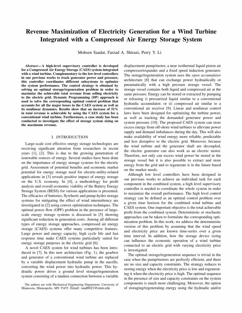
A novel CAES system for wind turbines has been intro-duced in [7]. In this new architecture (Fig. 1), the gearboxand generator of a conventional wind turbine are replacedby a variable displacement hydraulic pump in the nacelle,converting the wind power into hydraulic power. This hy-draulic power drives a ground level storage/regenerationsystem consisting of a tandem connection between a variable
The authors are with Mechanical Engineering Department, University ofMinnesota, Minneapolis, MN 55455. Email: [email protected]
displacement pump/motor, a near isothermal liquid piston aircompressor/expander and a fixed speed induction generator.The storage/regeneration system uses the open accumulatorarchitecture [8] that can exchange power hydraulically orpneumatically with a high pressure storage vessel. Thestorage vessel contains both liquid and compressed air at thesame pressure. Energy can be stored or extracted by pumpingor releasing i) pressurized liquid similar to a conventionalhydraulic accumulator; or ii) compressed air similar to aconventional air receiver [9]. Linear and nonlinear controllaws have been designed for optimizing the turbine power,as well as tracking the demanded generator power andsystem pressure [10]. The proposed CAES system can storeexcess energy from off-shore wind turbines to alleviate powersupply and demand imbalances during the day. This will alsomake availability of wind energy more reliable, predictableand less disruptive to the electric grid. Moreover, becausethe wind turbine and the generator shaft are decoupled,the electric generator can also work as an electric motor.Therefore, not only can excess wind power be stored in thestorage vessel but it is also possible to extract and storeenergy from the grid and to regenerate it in the future basedon the market needs.
Although low level controllers have been designed inour previous works to achieve an individual task for eachcomponent in the combined system, a high level supervisorycontroller is needed to coordinate the whole system in orderto maximize the overall performance. The high level controlstrategy can be defined as an optimal control problem overa given time horizon for the combined wind turbine andCAES system. One important objective is the total achievableprofit from the combined system. Deterministic or stochasticapproaches can be taken to formulate the corresponding opti-mization problem. In this work, we address the deterministicversion of this problem by assuming that the wind speedand electricity price are known time-series over a giventime interval. In addition, how the storage device sizingcan influence the economic operation of a wind turbineconnected to an electric grid with varying electricity priceis investigated.
The optimal storage/regeneration sequence is trivial in thecase when the pump/motors are perfectly efficient, and thereare no size and capacity constraints. The strategy reduces tostoring energy when the electricity price is low and regenerat-ing it when the electricity price is high. The optimal sequencein the presence of size and capacity constraints on the systemcomponents is much more challenging. Moreover, the optionof storaging/regenerating energy using the hydraulic and/or
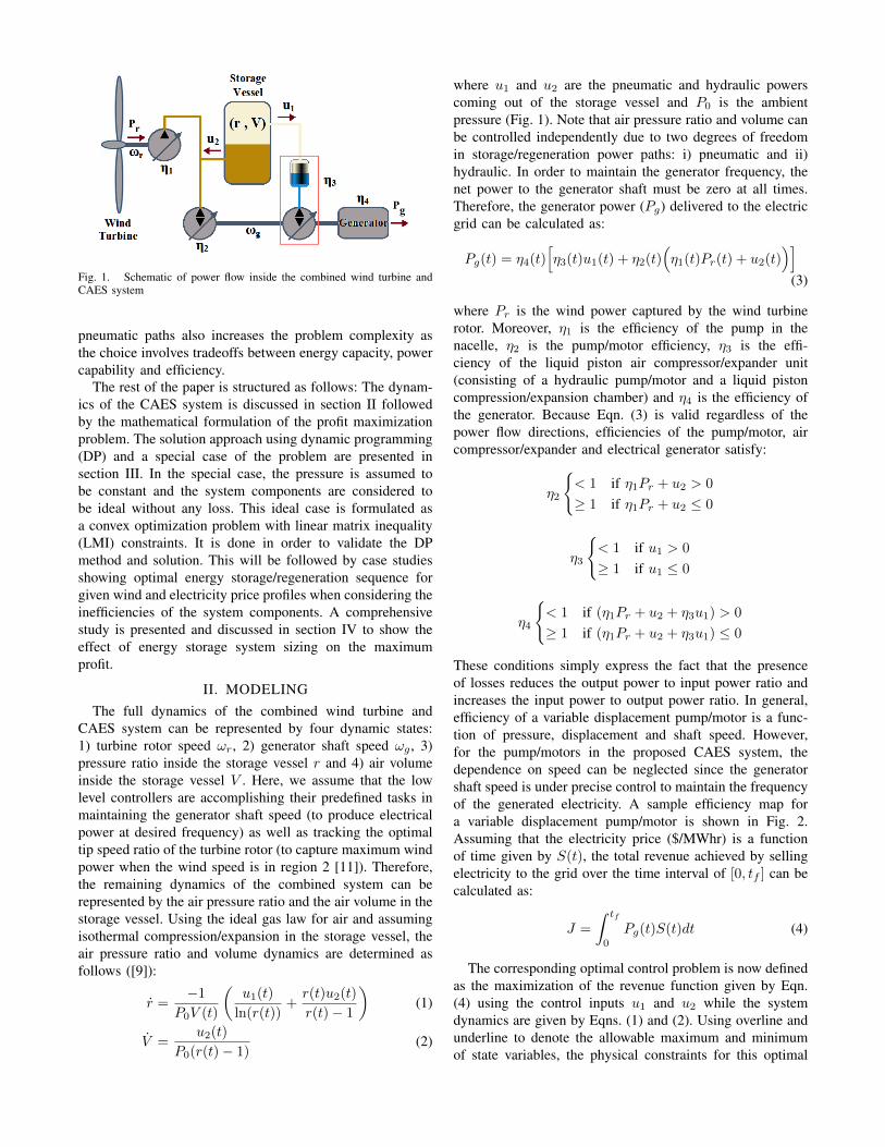
Fig. 1. Schematic of power flow inside the combined wind turbine andCAES system
pneumatic paths also increases the problem complexity asthe choice involves tradeoffs between energy capacity, powercapability and efficiency.
The rest of the paper is structured as follows: The dynam-ics of the CAES system is discussed in section II followedby the mathematical formulation of the profit maximizationproblem. The solution approach using dynamic programming(DP) and a special case of the problem are presented insection III. In the special case, the pressure is assumed tobe constant and the system components are considered tobe ideal without any loss. This ideal case is formulated asa convex optimization problem with linear matrix inequality(LMI) constraints. It is done in order to validate the DPmethod and solution. This will be followed by case studiesshowing optimal energy storage/regeneration sequence forgiven wind and electricity price profiles when considering theinefficiencies of the system components. A comprehensivestudy is presented and discussed in section IV to show theeffect of energy storage system sizing on the maximumprofit.
II. MODELINGThe full dynamics of the combined wind turbine and
CAES system can be represented by four dynamic states:1) turbine rotor speed ωr, 2) generator shaft speed ωg , 3)pressure ratio inside the storage vessel r and 4) air volumeinside the storage vessel V . Here, we assume that the lowlevel controllers are accomplishing their predefined tasks inmaintaining the generator shaft speed (to produce electricalpower at desired frequency) as well as tracking the optimaltip speed ratio of the turbine rotor (to capture maximum windpower when the wind speed is in region 2 [11]). Therefore,the remaining dynamics of the combined system can berepresented by the air pressure ratio and the air volume in thestorage vessel. Using the ideal gas law for air and assumingisothermal compression/expansion in the storage vessel, theair pressure ratio and volume dynamics are determined asfollows ([9]):
r =−1
P0V (t)
(u1(t)
ln(r(t))+r(t)u2(t)
r(t)− 1
)(1)
V =u2(t)
P0(r(t)− 1)(2)
where u1 and u2 are the pneumatic and hydraulic powerscoming out of the storage vessel and P0 is the ambientpressure (Fig. 1). Note that air pressure ratio and volume canbe controlled independently due to two degrees of freedomin storage/regeneration power paths: i) pneumatic and ii)hydraulic. In order to maintain the generator frequency, thenet power to the generator shaft must be zero at all times.Therefore, the generator power (Pg) delivered to the electricgrid can be calculated as:
Pg(t) = η4(t)[η3(t)u1(t) + η2(t)
(η1(t)Pr(t) + u2(t)
)](3)
where Pr is the wind power captured by the wind turbinerotor. Moreover, η1 is the efficiency of the pump in thenacelle, η2 is the pump/motor efficiency, η3 is the effi-ciency of the liquid piston air compressor/expander unit(consisting of a hydraulic pump/motor and a liquid pistoncompression/expansion chamber) and η4 is the efficiency ofthe generator. Because Eqn. (3) is valid regardless of thepower flow directions, efficiencies of the pump/motor, aircompressor/expander and electrical generator satisfy:
η2
{< 1 if η1Pr + u2 > 0
≥ 1 if η1Pr + u2 ≤ 0
η3
{< 1 if u1 > 0
≥ 1 if u1 ≤ 0
η4
{< 1 if (η1Pr + u2 + η3u1) > 0
≥ 1 if (η1Pr + u2 + η3u1) ≤ 0
These conditions simply express the fact that the presenceof losses reduces the output power to input power ratio andincreases the input power to output power ratio. In general,efficiency of a variable displacement pump/motor is a func-tion of pressure, displacement and shaft speed. However,for the pump/motors in the proposed CAES system, thedependence on speed can be neglected since the generatorshaft speed is under precise control to maintain the frequencyof the generated electricity. A sample efficiency map fora variable displacement pump/motor is shown in Fig. 2.Assuming that the electricity price ($/MWhr) is a functionof time given by S(t), the total revenue achieved by sellingelectricity to the grid over the time interval of [0, tf ] can becalculated as:
J =
∫ tf
0
Pg(t)S(t)dt (4)
The corresponding optimal control problem is now definedas the maximization of the revenue function given by Eqn.(4) using the control inputs u1 and u2 while the systemdynamics are given by Eqns. (1) and (2). Using overline andunderline to denote the allowable maximum and minimumof state variables, the physical constraints for this optimal

control problem can be summarized as follows:
r ≤ r(t) ≤ r (5)
V ≤ V (t) ≤ V (6)
|η1(t)Pr(t) + u2(t)| ≤ P pm(r) (7)
|u1(t)| ≤ P ce(r) (8)
|Pg(t)| ≤ P g (9)
where Eqn. (5) and (6) are due to allowable pressure range ofthe CAES system and the maximum capacity of the storagevessel. Eqns. (7), (8) and (9) show the maximum powercapability of the pump/motor, air compressor/expander andelectrical generator/motor, where P pm, P ce and P g arethe rated powers for each component, respectively. Oneadditional constraint is required to guarantee that the initialand final energy level in the storage vessel are the same(i.e. total energy sold to the electric grid is obtained fromthe given time interval not from any prior storage). Thisconstraint can be written as:∫ tf
0
(u1(t) + u2(t))dt = 0 (10)
Pressure Ratio (r)
Dis
plac
emen
t %
50 100 150 200 250 300 3501
0.5
0
0.5
1
50
60
70
80
90
Fig. 2. Energetic efficiency of a pump/motor as a function of displacementand pressure ratio
III. SOLUTION APPROACH
Due to the nonlinear system dynamics and complex effi-ciency mappings for different components in the integratedwind turbine and CAES system, analytical approaches tosolve the optimal control problem are difficult to apply. Hereinstead, deterministic Dynamic Programming (DP) approachis used to find the optimal storage/regeneration strategy andpower path (pneumatic and/or hydraulic). By discretizing thesystem dynamics in time and rearranging Eqns. (1) and (2),u1 and u2 can be written as:
u1(i) = −P0ln
(r(i)
)∆t(i)
[r(i)∆V (i) + V (i)∆r(i)
](11)
u2(i) = P0
(r(i)− 1)
∆V (i)
∆t(i)(12)
where i is the discrete time index and ∆r and ∆V arethe pressure ratio and volume change from time t(i) to
t(i+1). Now, by discretizing the state space (r-V ), the optimalsequence of r and V that maximizes the total revenue andsatisfies all the constraints can be found by the DP searchmethod.
In order to check the performance and accuracy of thedeveloped DP code, a benchmark case study has been definedand solved. In this benchmark case, we assume that onedegree of control freedom is utilized to maintain the systempressure ratio at the desired value rd all the time. In thissituation, u1 and u2 coordinate with each other to maintainthe pressure ratio. This coordination can be obtained as:
u2(t) = αu1(t) (13)
where α is:
α =1− rdrdln(rd)
(14)
The second assumption for the benchmark case is that all theefficiencies are equal to 100% (ideal system with no loss).In summary, the optimal control problem for this benchmarkcase can be mathematically formulated as:
u∗1 = arg maxu1(.)
(∫ tf
0
u1(t)S(t)dt)
(15)
such that:
0 ≤ e(t) ≤ e|u1(t)| ≤ P ce(rd)
|Pr(t) + (α+ 1)u1(t)| ≤ P g∫ tf
0
u1(t)dt = 0
where e is the energy stored in the pressure vessel and canbe calculated as [8]:
e(t) = P0V (t)(rdln(rd)− rd + 1
)(16)
The significance of the benchmark case is that the optimalcontrol problem can be formulated as a convex optimizationproblem, with a linear cost function and a number of linearmatrix inequalities (LMI) describing all the constraints. Indiscrete time domain, using the forward difference methodto evaluate time derivatives, we have:
U =1
(α+ 1)∆t
(DXDT −X
)(17)
where
U = Diag[u1(t1), · · · , u1(tn)
]X = E − e(t0)In×n
E = Diag[e(t1), · · · , e(tn)
]D = Ln
† (18)
Note that t0 to tn are the discrete time nodes while weassume the state of charge for the pressure vessel at t0
†Lower shift matrix with ones only on the subdiagonal and zeroeselsewhere.
is known and is equal to e(t0). Now, the optimal controlproblem in discrete time domain can be formulated as:
X∗ = arg maxX
(ST (D − I)XF
)(19)
where F is a column vector of ones (n-by-1) and S is theelectricity price vector defined as:
S =[S(t1) · · · S(tf )
]TMoreover, all the constraints can be summarized as:
− e(t0)I ≤ X ≤(e− e(t0)
)I
−min(P gI +W, (α+ 1)P ceI
)∆t ≤ DXDT −X ≤
≤ min(P gI −W, (α+ 1)P ceI
)∆t
− (α+ 1)∆tε ≤(DTF
)TXDTF − FTXF ≤ (α+ 1)∆tε
(20)
where I is the identity matrix and W is the rotor powermatrix defined as:
W = Diag[Pr(t1), · · · , Pr(tn)
](21)
Note that ε in Eqn. (20) is a small positive value thatdetermines the strictness of the equality constraint in Eqn.(10).
To compare the results of DP and convex optimizationmethods, the optimal control problem is solved for the windpower and electricity price profiles shown in Fig. 3 (top).The wind power profile is calculated based on a series of10-min average wind speed recorded at the elevation of 60m[12]. Assuming that the wind turbine has a rotor with radiusof 65m and rated power of 2.5MW, the captured wind powercan be calculated as:
Pr(t) =1
2ρairπR
2rC∗pV
3wind (22)
where ρair is the air density at ambient condition and C∗p '0.48 is the power coefficient at the optimal tip speed ratio(' 8.1) [11]. Electricity price profile is an hourly marginalprice per electrical bus provided by the Electric ReliabilityCouncil of Texas (ERCOT) [13]. A total volume of 500m3 isconsidered for the pressure vessel. At pressure ratio of 200,this volume is equivalent to about 12MWhr of energy. Inaddition, the generator and the air compressor/expander ratedpowers are assumed to be 2.5MW and 2MW, respectively.Results of this benchmark case study are shown in Fig. 3(middle and bottom). As can be observed, the DP and convexoptimization solutions match well with each other. Note thatfor both approaches, a total number of 300 points is used todiscretize time domain (∆t = 24min).
In the case of no energy storage, the total revenue that canbe achieved by selling the captured wind power to the electricgrid is $7800 over the given 5-day time horizon. However,according to the optimal solution (DP or convex optimiza-tion), by providing a 12MWhr energy storage capacity forthe wind turbine, the total revenue can raise up to $12000over the same time range which is about 54% increase in thetotal revenue. Note that the electrical generator can function
as an electric motor as well. However, in the benchmarkcase an ideal system is assumed where all the componentsare lossless. Therefore, this improvement can not be realisticsince there exist inefficiencies in the integrated system whichwill be addressed in the next section.
0 12 24 36 48 60 72 84 96 108 1200
0.5
1
1.5
2
2.5
3
Capt
ured
Wind
Pow
er (M
W)
Time (hr)
0 12 24 36 48 60 72 84 96 108 1200
50
100
150
200
250
300
Elec
tricit
y Pric
e ($/M
Whr
)
Captured Wind Energy
0 12 24 36 48 60 72 84 96 108 1202
1
0
1
2
3
Gene
rato
r Pow
er (M
W)
Time (hr)
0 12 24 36 48 60 72 84 96 108 1200
50
100
150
200
250
Elec
tricit
y Pric
e ($/M
Whr
)
DP Solution LMI Solution
0 20 40 60 80 100 1200
2
4
6
8
10
12
Time (hr)
Stor
age V
esse
l Ene
rgy (
MWhr
)
DP Solution LMI Solution
Fig. 3. Comparison between DP solution and convex optimization ap-proaches. Captured wind power and electricity price profiles (top); Generatorpower (middle); Energy level inside the storage vessel (bottom)
IV. CASE STUDIESAs mentioned before, due to nonlinear system dynamics
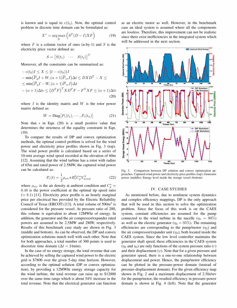
and complex efficiency mappings, DP is the only approachthat will be used in this section to solve the optimizationproblem. Since the focus of this work is on the CAESsystem, constant efficiencies are assumed for the pumpconnected to the wind turbine in the nacelle (η1 = 90%)as well as the electric generator (η4 = 95%). The remainingefficiencies are corresponding to the pump/motor (η2) andthe air compressor/expander unit (η3), both located inside theCAES system. Since the low level controller maintains thegenerator shaft speed, these efficiencies in the CAES system(η2 and η3) are only functions of the system pressure ratio (r)and their displacement (x). Note that for a given pressure andgenerator speed, there is a one-to-one relationship betweendisplacement and power. Hence, the pump/motor efficiencycan be plotted in the pressure-power domain (instead ofpressure-displacement domain). For the given efficiency mapshown in Fig. 2 and a maximum displacement of 2.5lit/revfor the pump/motor, the resulted efficiency in pressure-powerdomain is shown in Fig. 4 (left). Note that the generator
frequency is assumed to be 60Hz. Here, we define the nom-inal power of the pump/motor to be the maximum hydraulicpower flowing out of the machine (pumping mode) at thefull displacement (x = 1) and the pressure of 200bar. In thisway, the corresponding nominal power of the pump/motorwill be about 3MW.
Hydraulic Transformer
Pressure Ratio
Pow
er (M
W) Motoring Mode
Pumping Mode
Not Feasible (x < 1)
Not Feasible (x > +1)
50 100 150 200 250 300 3505
4
3
2
1
0
1
2
3
4
5
Pressure Ratio
Pow
er (M
W)
Air Compressor/Expander
Expansion Mode
Compression Mode
Not Feasible
Not Feasible
50 100 150 200 250 300 3505
4
3
2
1
0
1
2
3
4
5
0.5
1
1.5
2
Fig. 4. Pump/motor (left) and air compressor/expander (right) efficiencymap as a function of system pressure ratio and power. Note that in orderfor Eqn. (3) to be valid regardless of power flow direction, the pump/motorefficiency in the pumping mode and the air compressor/expander efficiencyin the compression mode are considered to be 1/η where 0 ≤ η ≤ 1 is thephysical efficiency.
The same approach has been taken to find and map the effi-ciency of the liquid piston air compressor/expander as shownin Fig. 4 (right). Note that the air compressor/expanderunit includes a variable displacement pump/motor with amaximum displacement of 1.6lit/rev and a liquid pistoncompression/expansion chamber with a total heat transfercapability of 85kW/K [14]. These result in a nominal powerof 2MW for the air compressor/expander used for the nextcase study.
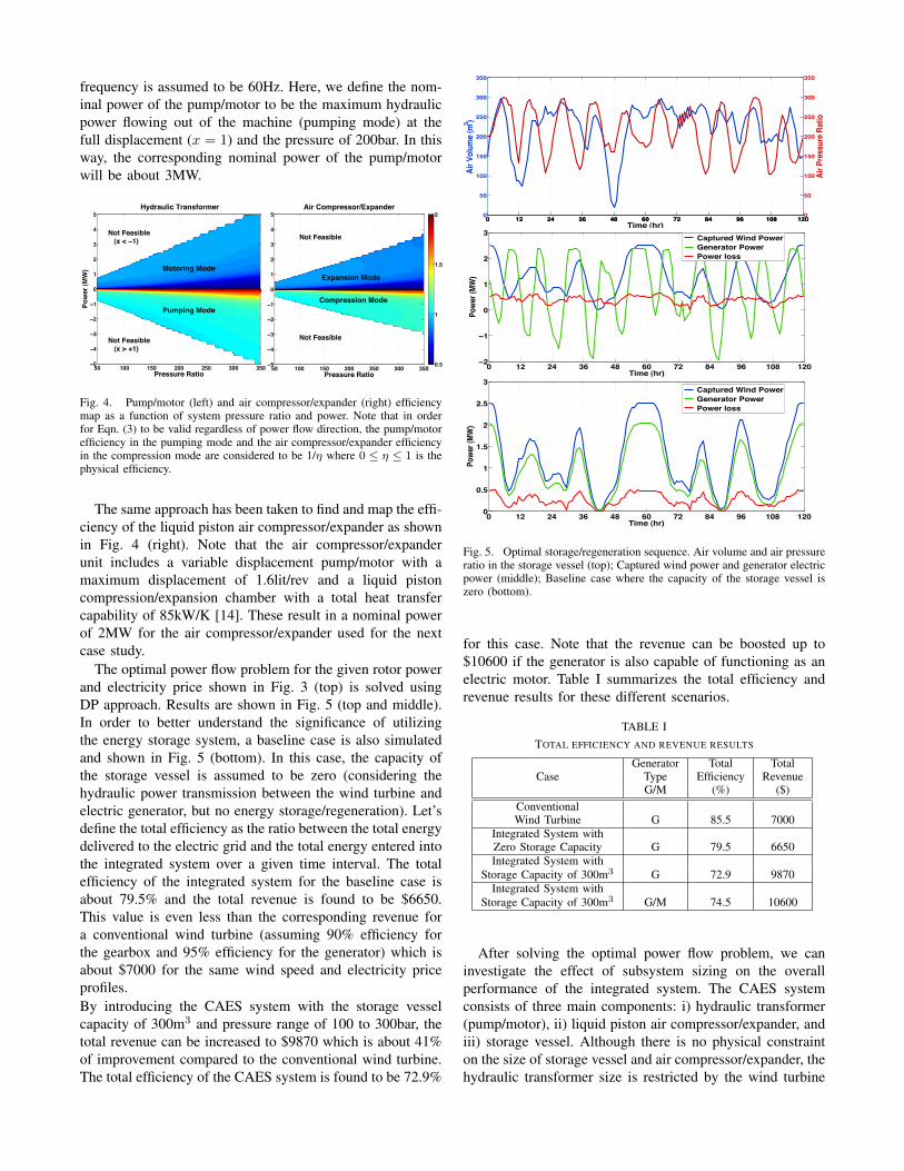
The optimal power flow problem for the given rotor powerand electricity price shown in Fig. 3 (top) is solved usingDP approach. Results are shown in Fig. 5 (top and middle).In order to better understand the significance of utilizingthe energy storage system, a baseline case is also simulatedand shown in Fig. 5 (bottom). In this case, the capacity ofthe storage vessel is assumed to be zero (considering thehydraulic power transmission between the wind turbine andelectric generator, but no energy storage/regeneration). Let’sdefine the total efficiency as the ratio between the total energydelivered to the electric grid and the total energy entered intothe integrated system over a given time interval. The totalefficiency of the integrated system for the baseline case isabout 79.5% and the total revenue is found to be $6650.This value is even less than the corresponding revenue fora conventional wind turbine (assuming 90% efficiency forthe gearbox and 95% efficiency for the generator) which isabout $7000 for the same wind speed and electricity priceprofiles.By introducing the CAES system with the storage vesselcapacity of 300m3 and pressure range of 100 to 300bar, thetotal revenue can be increased to $9870 which is about 41%of improvement compared to the conventional wind turbine.The total efficiency of the CAES system is found to be 72.9%
0 12 24 36 48 60 72 84 96 108 1200
50
100
150
200
250
300
350
Air V
olum
e (m3 )
Time (hr)0 12 24 36 48 60 72 84 96 108 1200
50
100
150
200
250
300
350
Air P
ress
ure R
atio
0 12 24 36 48 60 72 84 96 108 1202
1
0
1
2
3
Time (hr)
Powe
r (M
W)
Captured Wind Power Generator Power Power loss
0 12 24 36 48 60 72 84 96 108 1200
0.5
1
1.5
2
2.5
3
Time (hr)
Powe
r (MW
)
Captured Wind Power Generator Power Power loss
Fig. 5. Optimal storage/regeneration sequence. Air volume and air pressureratio in the storage vessel (top); Captured wind power and generator electricpower (middle); Baseline case where the capacity of the storage vessel iszero (bottom).
for this case. Note that the revenue can be boosted up to$10600 if the generator is also capable of functioning as anelectric motor. Table I summarizes the total efficiency andrevenue results for these different scenarios.
TABLE ITOTAL EFFICIENCY AND REVENUE RESULTS
Generator Total TotalCase Type Efficiency Revenue
G/M (%) ($)ConventionalWind Turbine G 85.5 7000
Integrated System withZero Storage Capacity G 79.5 6650Integrated System with
Storage Capacity of 300m3 G 72.9 9870Integrated System with
Storage Capacity of 300m3 G/M 74.5 10600
After solving the optimal power flow problem, we caninvestigate the effect of subsystem sizing on the overallperformance of the integrated system. The CAES systemconsists of three main components: i) hydraulic transformer(pump/motor), ii) liquid piston air compressor/expander, andiii) storage vessel. Although there is no physical constrainton the size of storage vessel and air compressor/expander, thehydraulic transformer size is restricted by the wind turbine
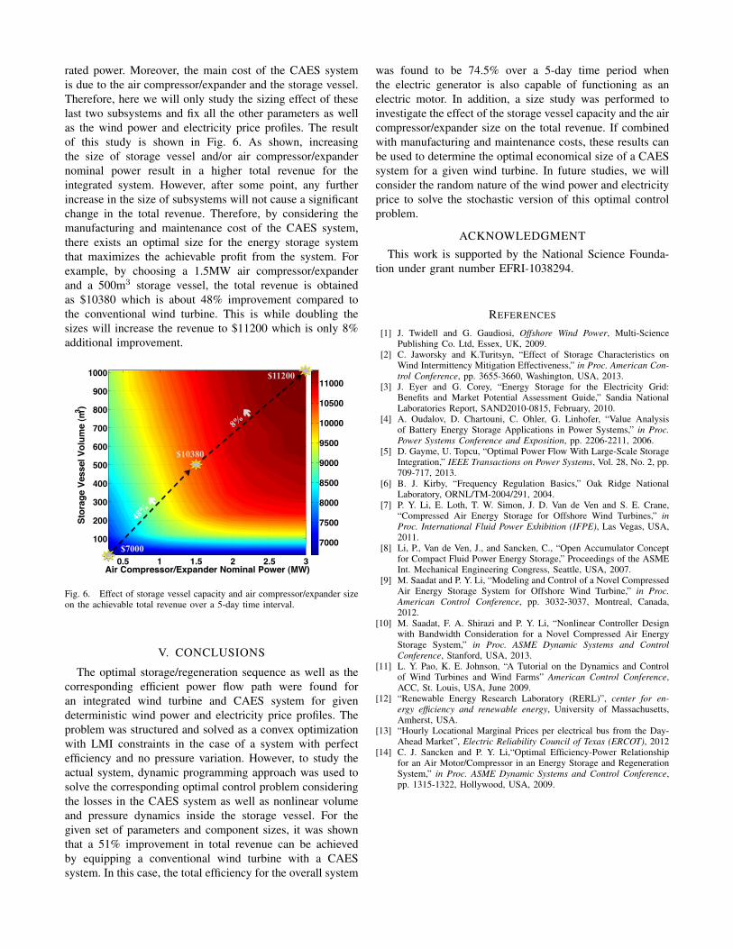
rated power. Moreover, the main cost of the CAES systemis due to the air compressor/expander and the storage vessel.Therefore, here we will only study the sizing effect of theselast two subsystems and fix all the other parameters as wellas the wind power and electricity price profiles. The resultof this study is shown in Fig. 6. As shown, increasingthe size of storage vessel and/or air compressor/expandernominal power result in a higher total revenue for theintegrated system. However, after some point, any furtherincrease in the size of subsystems will not cause a significantchange in the total revenue. Therefore, by considering themanufacturing and maintenance cost of the CAES system,there exists an optimal size for the energy storage systemthat maximizes the achievable profit from the system. Forexample, by choosing a 1.5MW air compressor/expanderand a 500m3 storage vessel, the total revenue is obtainedas $10380 which is about 48% improvement compared tothe conventional wind turbine. This is while doubling thesizes will increase the revenue to $11200 which is only 8%additional improvement.
Air Compressor/Expander Nominal Power (MW)
Stor
age
Vess
el V
olum
e (m
3 )
0.5 1 1.5 2 2.5 3
100
200
300
400
500
600
700
800
900
1000
7000
7500
8000
8500
9000
9500
10000
10500
11000
8% é
48%
é
$7000
$10380
$11200
Fig. 6. Effect of storage vessel capacity and air compressor/expander sizeon the achievable total revenue over a 5-day time interval.
V. CONCLUSIONS
The optimal storage/regeneration sequence as well as thecorresponding efficient power flow path were found foran integrated wind turbine and CAES system for givendeterministic wind power and electricity price profiles. Theproblem was structured and solved as a convex optimizationwith LMI constraints in the case of a system with perfectefficiency and no pressure variation. However, to study theactual system, dynamic programming approach was used tosolve the corresponding optimal control problem consideringthe losses in the CAES system as well as nonlinear volumeand pressure dynamics inside the storage vessel. For thegiven set of parameters and component sizes, it was shownthat a 51% improvement in total revenue can be achievedby equipping a conventional wind turbine with a CAESsystem. In this case, the total efficiency for the overall system
was found to be 74.5% over a 5-day time period whenthe electric generator is also capable of functioning as anelectric motor. In addition, a size study was performed toinvestigate the effect of the storage vessel capacity and the aircompressor/expander size on the total revenue. If combinedwith manufacturing and maintenance costs, these results canbe used to determine the optimal economical size of a CAESsystem for a given wind turbine. In future studies, we willconsider the random nature of the wind power and electricityprice to solve the stochastic version of this optimal controlproblem.
ACKNOWLEDGMENT
This work is supported by the National Science Founda-tion under grant number EFRI-1038294.
REFERENCES
[1] J. Twidell and G. Gaudiosi, Offshore Wind Power, Multi-SciencePublishing Co. Ltd, Essex, UK, 2009.
[2] C. Jaworsky and K.Turitsyn, “Effect of Storage Characteristics onWind Intermittency Mitigation Effectiveness,” in Proc. American Con-trol Conference, pp. 3655-3660, Washington, USA, 2013.
[3] J. Eyer and G. Corey, “Energy Storage for the Electricity Grid:Benefits and Market Potential Assessment Guide,” Sandia NationalLaboratories Report, SAND2010-0815, February, 2010.
[4] A. Oudalov, D. Chartouni, C. Ohler, G. Linhofer, “Value Analysisof Battery Energy Storage Applications in Power Systems,” in Proc.Power Systems Conference and Exposition, pp. 2206-2211, 2006.
[5] D. Gayme, U. Topcu, “Optimal Power Flow With Large-Scale StorageIntegration,” IEEE Transactions on Power Systems, Vol. 28, No. 2, pp.709-717, 2013.
[6] B. J. Kirby, “Frequency Regulation Basics,” Oak Ridge NationalLaboratory, ORNL/TM-2004/291, 2004.
[7] P. Y. Li, E. Loth, T. W. Simon, J. D. Van de Ven and S. E. Crane,“Compressed Air Energy Storage for Offshore Wind Turbines,” inProc. International Fluid Power Exhibition (IFPE), Las Vegas, USA,2011.
[8] Li, P., Van de Ven, J., and Sancken, C., “Open Accumulator Conceptfor Compact Fluid Power Energy Storage,” Proceedings of the ASMEInt. Mechanical Engineering Congress, Seattle, USA, 2007.
[9] M. Saadat and P. Y. Li, “Modeling and Control of a Novel CompressedAir Energy Storage System for Offshore Wind Turbine,” in Proc.American Control Conference, pp. 3032-3037, Montreal, Canada,2012.
[10] M. Saadat, F. A. Shirazi and P. Y. Li, “Nonlinear Controller Designwith Bandwidth Consideration for a Novel Compressed Air EnergyStorage System,” in Proc. ASME Dynamic Systems and ControlConference, Stanford, USA, 2013.
[11] L. Y. Pao, K. E. Johnson, “A Tutorial on the Dynamics and Controlof Wind Turbines and Wind Farms” American Control Conference,ACC, St. Louis, USA, June 2009.
[12] “Renewable Energy Research Laboratory (RERL)”, center for en-ergy efficiency and renewable energy, University of Massachusetts,Amherst, USA.
[13] “Hourly Locational Marginal Prices per electrical bus from the Day-Ahead Market”, Electric Reliability Council of Texas (ERCOT), 2012
[14] C. J. Sancken and P. Y. Li,“Optimal Efficiency-Power Relationshipfor an Air Motor/Compressor in an Energy Storage and RegenerationSystem,” in Proc. ASME Dynamic Systems and Control Conference,pp. 1315-1322, Hollywood, USA, 2009.