Embed Size (px)
Citation preview
WASIIINGTON PVSI IC POWEAA SUPPI Y SYSTBM
No
QCI 6-4Rcv. No.
NDE dk I INSTRUCTIONEffccuvc Date
3I20I95
//YES + No
ULTRASONIC EXA1VHNATIONFEEDWATER NOZZLE INNER RADII
1.0 P RP E AND P
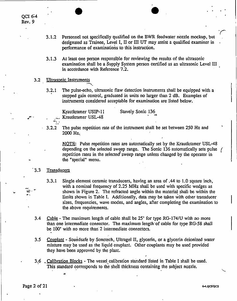
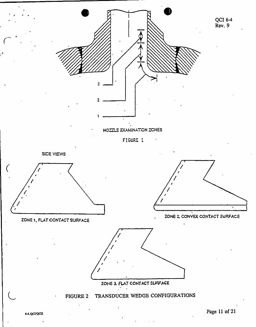
1.1 This procedure defines the requirements for manual, pulse-echo ultrasonic examinationof the feedwater nozzle inner radians, (Zones 1, 2, and 3), ASME Section XI,Category B-D. Scanning by this procedure is done from the reactor vessel O.D. walland nozzle surfaces using refracted. shear wave search units, Figure 1 illustrates theZones which can be effectively scanned .from the outside surfaces of the vessel plateand nozzle,
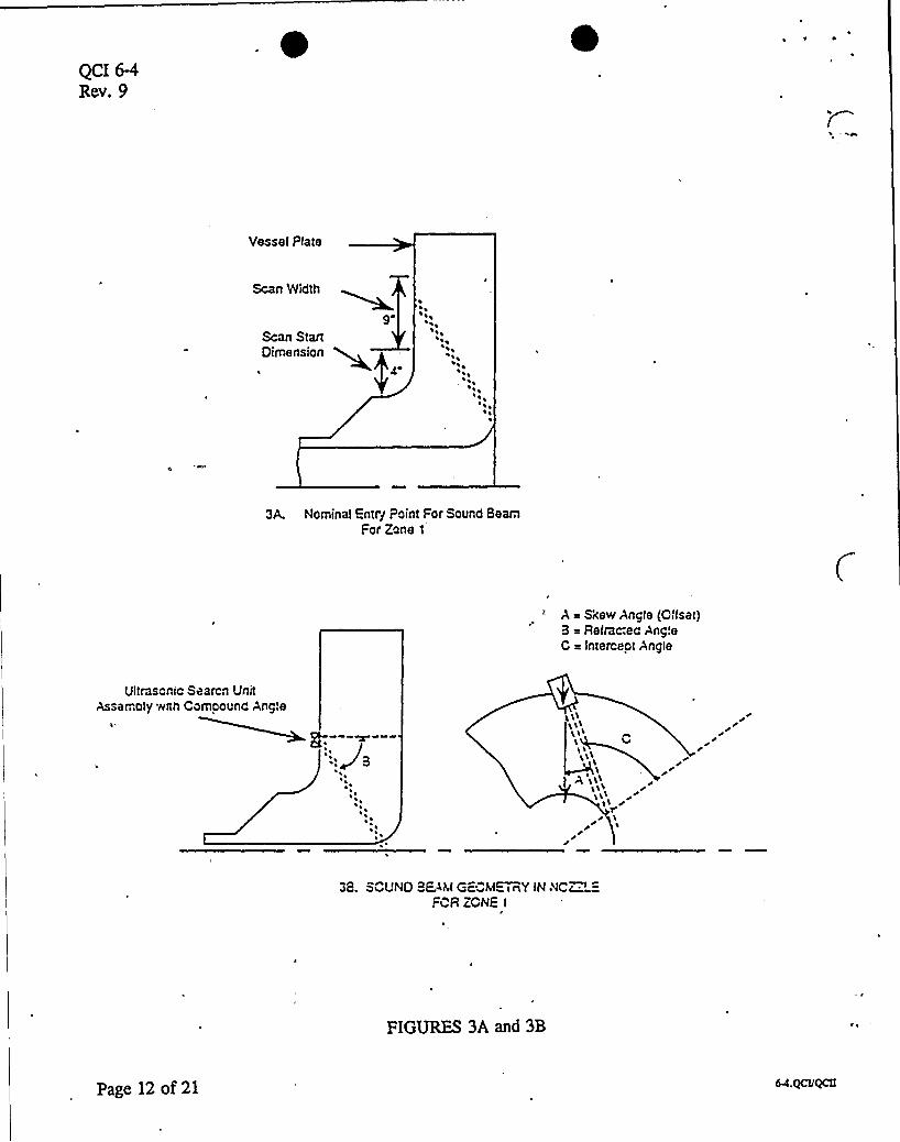
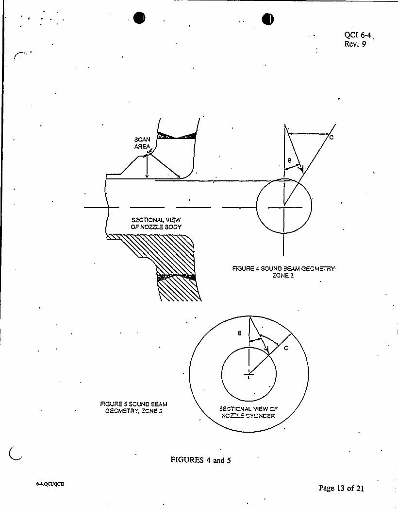
1.2 This procedure covers the angle beam shear wave technique that is unique to the nozzledesign. Specific refraction angles have been determined by individual nozzle geometryas depicted in Figures 3a, 3b, 4 and 5.
1.3 This instruction is intended to meet the requirements of Sections V and XI of theASME Boiler and Pressure Vessel Code (1989, no Addenda).
1.4 BWR Calibration Data listed in Table I have been predetermined from the SupplySystem's feedwater nozzle mockup so the qualified examiner need only use the vesselcalibration block representing the shell course containing the nozzle.
2.D ~SNone
3.0 ~EU NT
3.1 Personnel ualifications
3.1.1 Contractor and Supply System personnel performing examinations to therequirements of this instruction shall be certified to at least Level II inultrasonics in accordance with the requirements of Reference 7.2. Additionally,the examination team shall consist of at least one Level II or Level III inultrasonics qualified using the Supply System BWR feedwater nozzle mockupand this ultrasonic examination procedure per paragraph 4.3.
DEFr.APPROVhL/DA
WFM2 Rg
CIKClKDBY/DATE
SUPERSEDES ISSUE: (-./>j~ Rev. 8,Mated 03/10/93
r'-C -e~PAGE
I of 21
9512180151 951208FDR ADOCK 050003979 „„...PDR
~.QCVQCI I
QCI 6-'4
Rev. 9
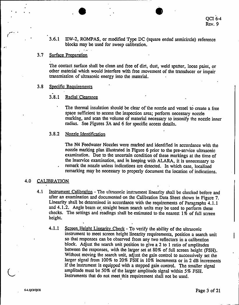
3.1.2 Personnel not specifically qualified on the BWR feedwater nozzle mockup, butdesignated as Trainee, Level I, II or III UT may assist a qualified examiner inperformance of examinations to this instruction.
3.1.3 At least one person responsible for reviewing the results of the ultrasonicexamination shall be a Supply System person certified as an ultrasonic Level IIIin accordance with Reference 7.2.
3.2 1 ni Instrument
3.2.1 The pulse-echo, ultrasonic flaw detection instruments shall be equipped with a
stepped gain control, graduated in units no larger than 2 dB. Examples ofinstruments considered acceptable for examination are listed below.
Krautkramer USIP-11: . Krautkramer USL-48
f6
3.2.2 The pulse repetition rate of the instrument shall be set between 250 Hz and2000 Hz.
NOTE: Pulse repetition rates are automatically set by the Krautkramer USL-48depending on the selected sweep range. The Sonic 136 automatically sets pulse
/'epetitionrates in the selected sweep range unless changed by the operator inthe "special" menu.
'.3 Transducers
3.3.1 Single element ceramic transducers, having an area of .44 to 1.0 square inch,with a nominal frequency of 2.25 MHz shall be used with specific wedges as
shown in Figure 2. The refracted angle within the material shall be within thelimits shown in Table I. Additionally, data may be taken with other transducersizes, frequencies, wave modes, and angles, after completing the examination tothe above requirements.
3.4 ~ale - The maximum length of cable shall be 25'or type RG-174/U with no morethan one intermediate connector. The maximum length'of cable for type RG-58 shallbe 100'ith no more than 2 intermediate connectors.
3.5 Qgygi~lan - Soundsafe by Sonotech, Ultragel II, glycerin, or a glycerin deionized watermixture may be used as the liquid couplant. Other couplants may be used providedthey have been approved by the plant.
36 .~lib 3 l 3 -Tb «I dlb 3 d dll Hi Tbl 3 bdlb d.
This standard corresponds to the shell thickness containing the subject nozzle.6
Page 2 of 21
QCI 6-4Rev. 9
3.6.1 IIW-2, ROMPAS, or modified Type DC (square ended semicircle) referenceblocks may be used for sweep calibration.
8
3.7 ~fPThe contact surface shall be clean and free of dirt, dust, weld spatter, loose paint, orother material which would interfere with free movement of the transducer or impairtransmission of ultrasonic energy into the material.
3.8 ifi R irmn
3. 8. I IL&hllI
The thermal insulation should be clear of'the nozzle and vessel to create a freespace sufficient to access the inspection area; perform necessary nozzlemarking, and scan the volume of material necessary to insonify the nozzle innerradius. See Figures 3'A and 6 for specific access details.
3.8.2 N zzl Id n ficati n
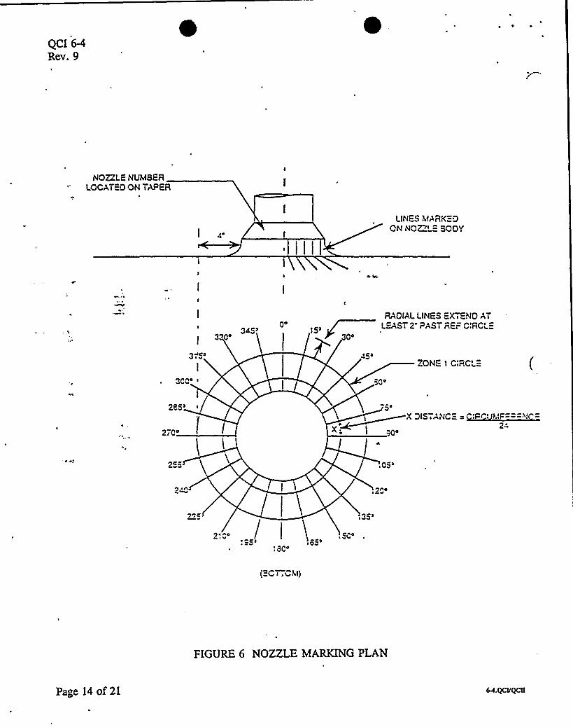
The N4 Feedwater Nozzles were marked and identified in accordance with thenozzle marking plan illustrated in Figure 6 prior to the pre-service ultrasonicexamination. Due to the uncertain condition of these markings at the time ofthe inservice examination, and in keeping with ALARA, it is unnecessary toremark the nozzle unless indications are detected. In which case, localizedremarking may be necessary to properly document the location of indications.
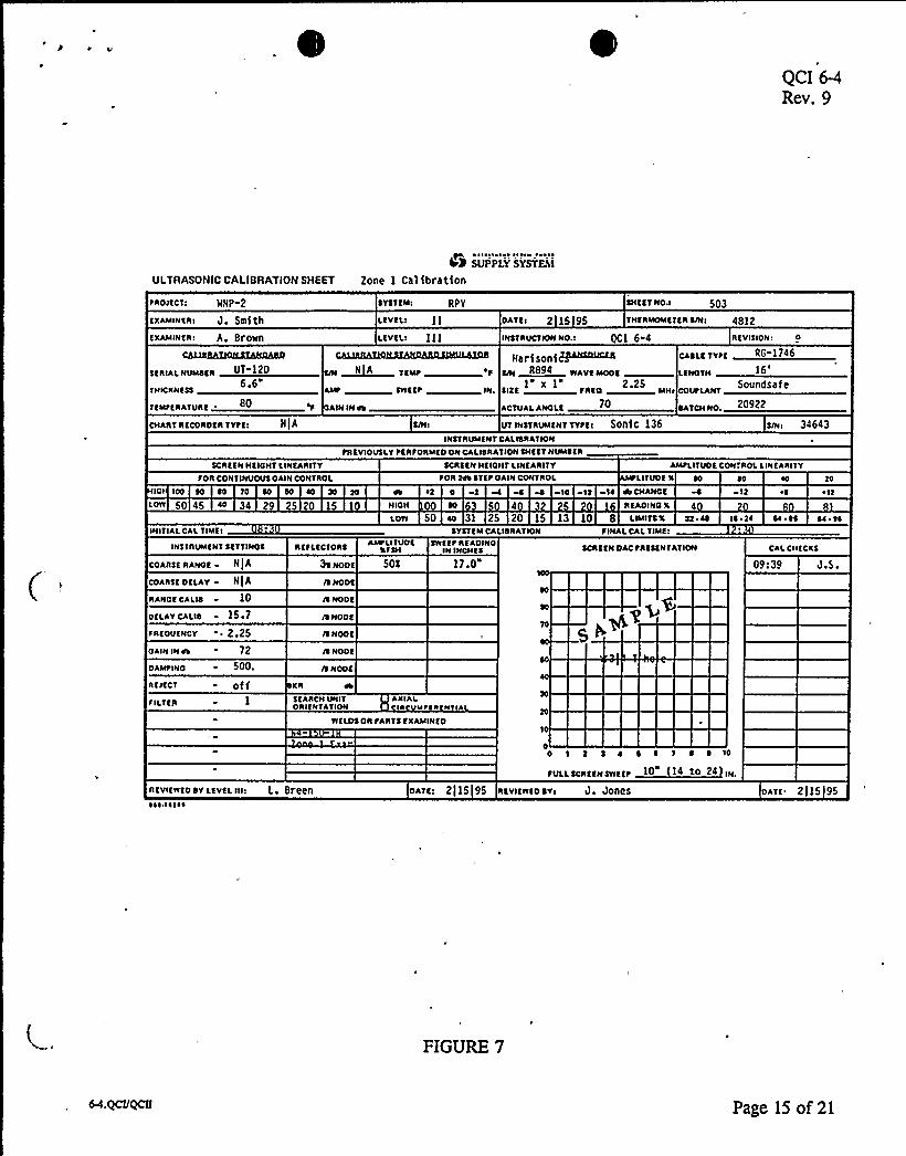
4.3 ~L774.1 In men alibrati n - The ultrasonic instrument linearity shall be checked before and
after an, examination and documented on the Calibration Data Sheet shown in Figure 7.Linearity shall be determined in accordance with the requirements of Paragraphs 4.1.1and 4.1.2. Angle beam or straight beam search units may be used to perform thesechecks. The settings and readings shall be estimated to the nearest 1% of full screenheight.
4.1.1 r n H i Lin ri h - To verify the ability of the ultrasonicinstrument to meet screen height linearity requirements, position a search unitso that responses can be observed from any two reflectors in a calibrationblock. Adjust the search unit position to give a 2 to 1 ratio of amplitudesbetween the responses, with the larger set at 80% of full screen height (FSH).Without moving the search unit, adjust the gain control to successively set thelarger signal from 100% to 20% FSH in 10% increments or in 2 dB incrementsif the instrument is equipped with a stepped gain control. The smaller signalamplitude must be 50% of the larger amplitude signal within 5% .FSH.Instruments that do not meet this requirement shall not be used.
Page 3 of 21
QCI 6-4Rev. 9
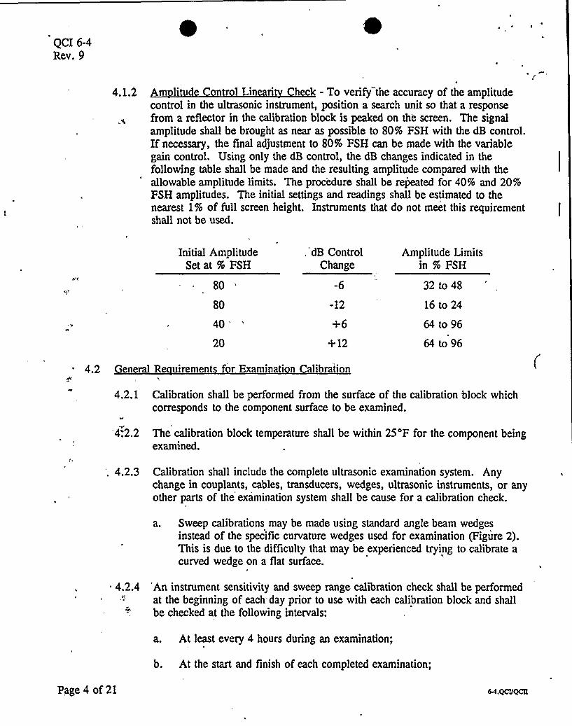
4.1.2 m l'1 Li ' - To verify the accuracy of the amplitude
control in the ultrasonic instrument, position a search unit so that a responsefrom a reflector in the calibration block is peaked on the screen, The signalamplitude shall be brought as near as possible to 80% FSH with the dB control.Ifnecessary, the final adjustment to 80% FSH can be made with the variablegain control. Using only the dB control, the dB changes indicated in thefollowing table shall be made and the resulting amplitude compared with theallowable amplitude limits. The procedure shall be repeated for 40% and 20%FSH amplitudes. The initial settings and readings shall be estimated to thenearest 1% of full screen height. Instruments that do not meet this requirementshall not be used.
Initial AmplitudeSet at % FSH
80
80
40'0
. dB ControlChange
-12
+12
Amplitude Limitsin % FSH
32 to 48
16 to 24
64 to 96
64 to 96
4.2 en R uiremen f r Examination alibration
4.2.1 Calibration shall be performed from the surface of the calibration block whichcorresponds to the component surface to be examined.
4".2.2 The calibration block temperature shall be within 25'F for the component beingexamined.
'. 4.2.3 Calibration shall include the complete ultrasonic examination system. Anychange in couplants, cables, transducers, wedges, ultrasonic instruments, or anyother parts of the examination system shall be cause for a calibration check.
a. Sweep calibrations may be made using standard angle beam wedgesinstead of the specific curvature wedges used for examination (Figure 2).This is due to the difficulty that may be experienced trying to calibrate acurved wedge on a flat surface.
4.2.4 'An instrument sensitivity and sweep range calibration check shall be performedat the beginning of each.day prior to use with each calibration block and shallbe checked at the following intervals:
a. At least every 4 hours during an examination;
b. At the start and finish of each completed examination;
Page 4 of 21
QCI 6-4Rev. 9
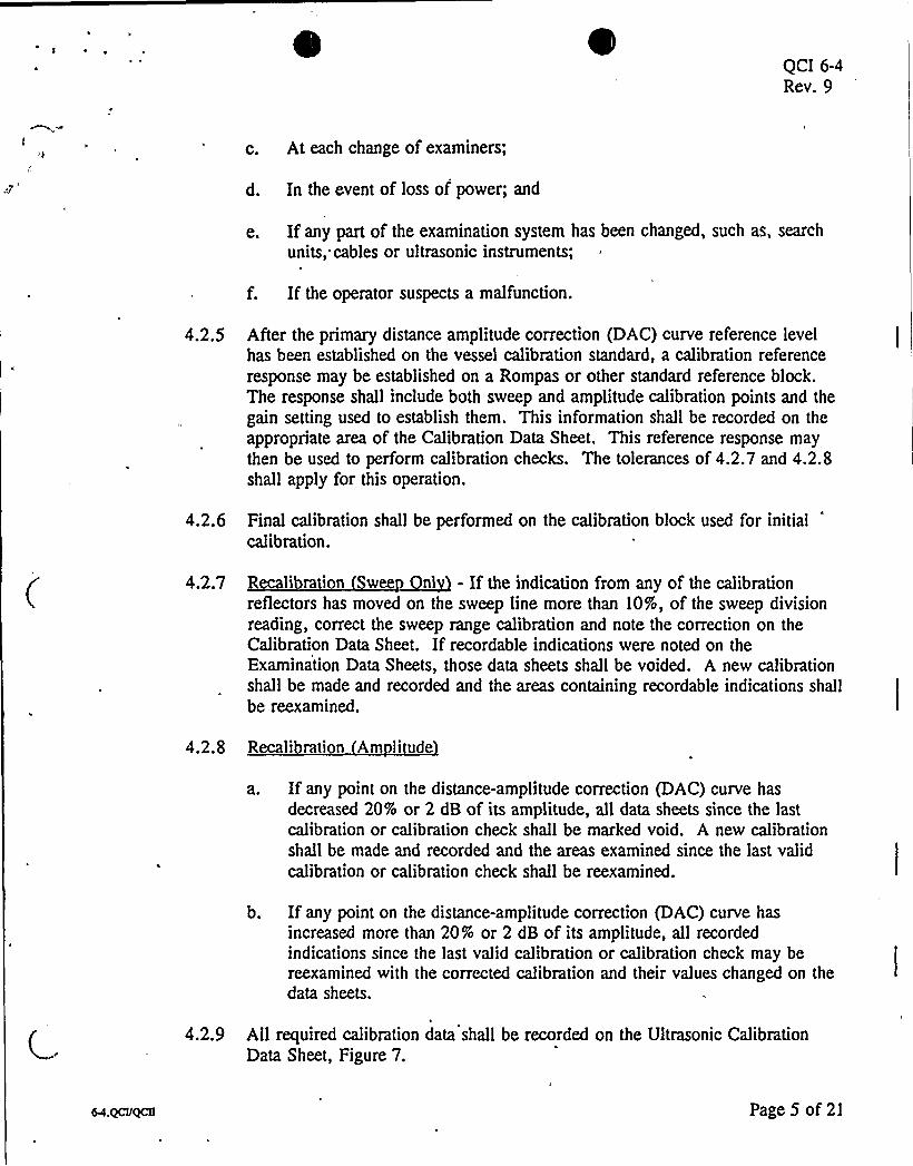
c. At each change of examiners;
d. In the event of loss of power; and
e. Ifany part of the examination system has been changed, such as, search
units, cables or ultrasonic instruments;
f. If the operator suspects a malfunction.
4.2.5 After the primary distance amplitude correction (DAC) curve reference levelhas been established on the vessel calibration standard, a calibration referenceresponse may be established on a Rompas or other standard reference block.The response shall include both sweep and amplitude calibration points and thegain setting used to establish them. This information shall be recorded on theappropriate area of the Calibration Data Sheet. This reference response maythen be used to perform calibration checks. The tolerances of 4.2.7 and 4.2.8shall apply for this operation.
4.2.6 Final calibration shall be performed on the calibration block used for initialcalibration.
4.2.7 Recalibration wee nl - If the indication from any of the calibrationreflectors has moved on the sweep line more than 10%, of the sweep divisionreading, correct the sweep range calibration and note the correction on theCalibration Data Sheet. Ifrecordable indications were noted on theExamination Data Sheets, those data sheets shall be voided. A new calibrationshall be made and recorded and the areas containing recordable indications shallbe reexamined.
4.2.8 Recali rati n Am litude
a. Ifany point on the distance-amplitude correction (DAC) curve hasdecreased 20% or 2 dB of its amplitude, all data sheets since the lastcalibration or calibration check shall be marked void. A new calibrationshall be made and recorded and the areas examined since the last validcalibration or calibration check shall be reexamined.
b. Ifany point on the distance-amplitude correction (DAC) curve hasincreased more than 20% or 2 dB of its amplitude, all recordedindications since the last valid calibration or calibration check may bereexamined with the corrected calibration and their values changed on thedata sheets.
4.2.9 All required calibration data shall be recorded on the Ultrasonic CalibrationData Sheet, Figure 7.
Page 5 of 21
QCI 6-4Rev. 9
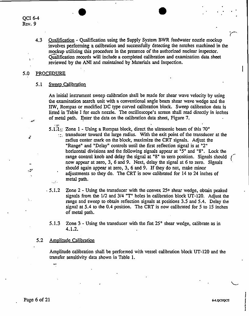
4.3 QSPByy'B-QMi~'
5 5 5 PylySy BBB 5~ \* Bpinvolves performing a calibration and successfully detecting the notches machined in themockup utilizing this procedure in the presence of the authorized nuclear inspector.Qualification records will include a completed calibration and examination data sheetreviewed by the ANI and maintained by Materials and Inspection.
5.5 5!QQZiJ!
5.1
An initial instrument sweep calibration shall be made for shear wave velocity by usingthe examination search unit with a conventional angle beam shear wave wedge and theIIW, Rompas or modified DC type curved calibration block. Sweep calibration data islisted in Table I for each nozzle. The oscilloscope's screen shall read directly in inchesof metal path. Enter the data on the calibration. data sheet, Figure 7.
5.1; 1.;.'. Zone 1 - Using a Rompas block, direct the ultrasonic beam of this70'„,
transducer toward the large radius. With the exit point of the transducer at theradius center mark on the block, maximize the CRT signals. Adjust the"Range" and "Delay" controls until the first reflection signal is at "2"horizontal divisions and the following signals appear at "5" and "8". Lock therange control knob and delay the signal at "8" to zero position. Signals shouldnow appear at zero, 3, 6 and 9. Next, delay the signal at 6 to zero. Signalsshould again appear at zero, 3, 6 and 9.,If they do not, make minoradjustments so they do. The CRT is now calibrated for 14 to 24 inches ofmetal path.
5.1.2 Zone 2 - Using the transducer with the convex 250 shear wedge, obtain peakedsignals from the 1/2 and 3/4 "T" holes in calibration block UT-120. Adjust therange and sweep to obtain reflection signals at positions 3.5 and 5.4. Delay thesignal at 5.4 to the 0.4 position. The CRT is now calibrated for 5 to 15 inchesof metal path.
5.1.3 Zone 3 - Using the transducer with the flat 25'hear wedge, calibrate as in4.1.2.
5.2 ~A
Amplitude calibration shall be performed with vessel calibration block UT-120 and thetransfer sensitivity data shown in Table 1.
Page 6 of 21
QCI 6-4Rev. 9
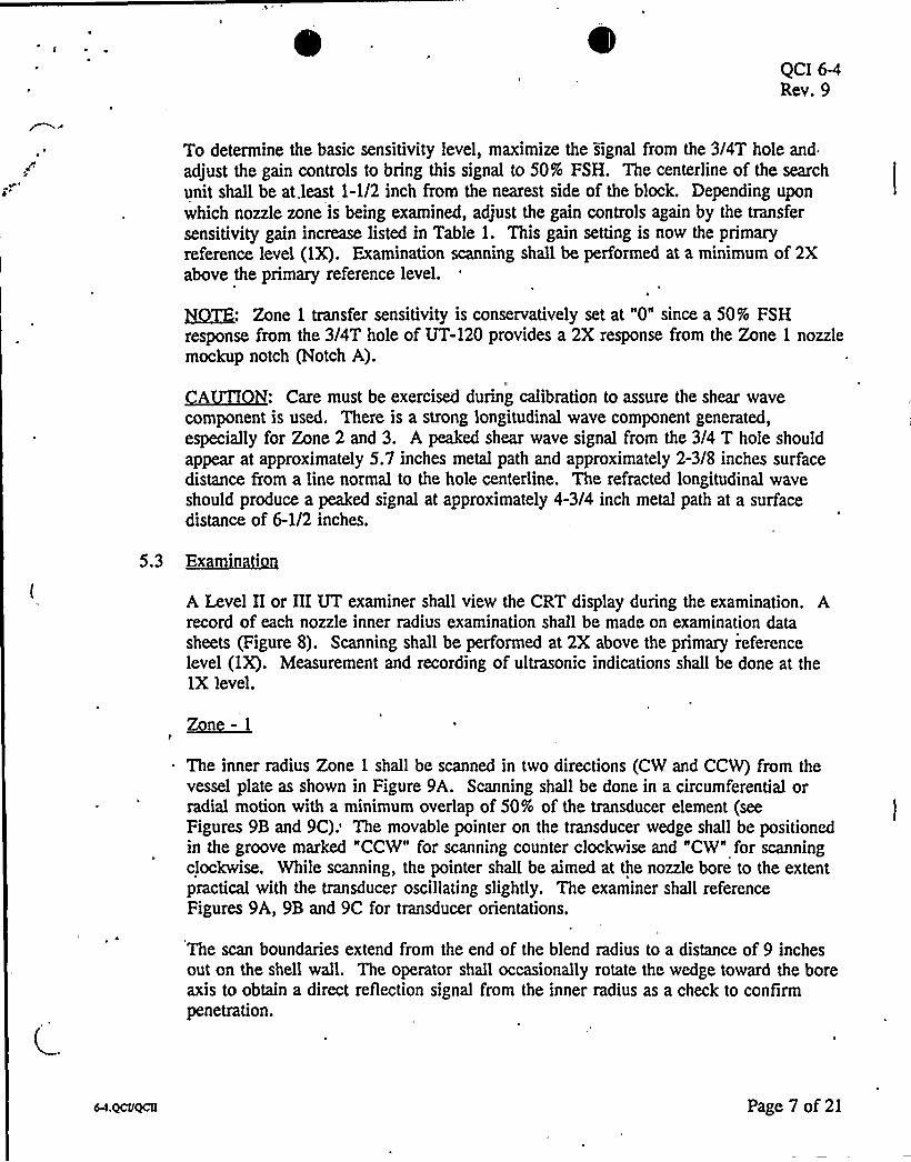
To determine the basic sensitivity level, maximize the signal from the 3/4T hole and
adjust the gain controls to bring this signal to 50% FSH. The centerline of the search
unit shall be at. least 1-1/2 inch from the nearest side of the block. Depending up'on
which nozzle zone is being examined, adjust the gain controls again by the transfersensitivity gain increase listed in Table 1. This gain setting is now the primaryreference level (1X). Examination scanning shall be performed at a minimum of 2Xabove the primary reference level.
gag: Zone 1 transfer sensitivity is conservatively set at "0" since a 50% FSHresponse from the 3/4T hole of UT-120 provides a 2X response from the Zone 1 nozzlemockup notch (Notch A).
QAQTI+g: Care must be exercised during calibration to assure the shear wavecomponent is used. There is a strong longitudinal wave component generated,especially for Zone 2 and 3. A peaked shear wave signal from the 3/4 T hole shouldappear at approximately 5.7 inches metal path and approximately 2-3/8 inches surfacedistance from a line normal to the hole centerline. The refracted longitudinal waveshould produce a peaked signal at approximately 4-3/4 inch metal path at a surfacedistance of 6-1/2 inches.
5.3 Ex in in
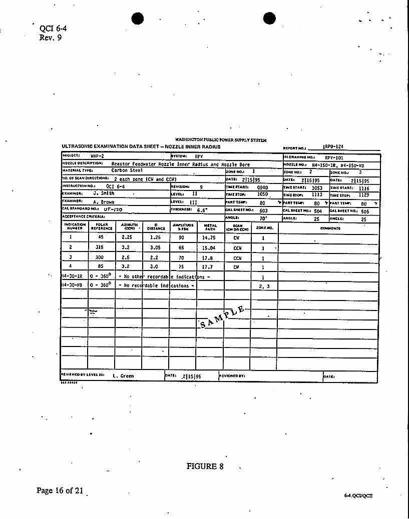
A Level II or IIIUT examiner shall view the CRT display during the examination. Arecord of each nozzle inner radius examination shall be made on examination datasheets (Figure 8). Scanning shall be performed at 2X above the primary referencelevel (1X). Measurement and recording of ultrasonic indications shall be done at the1X level.
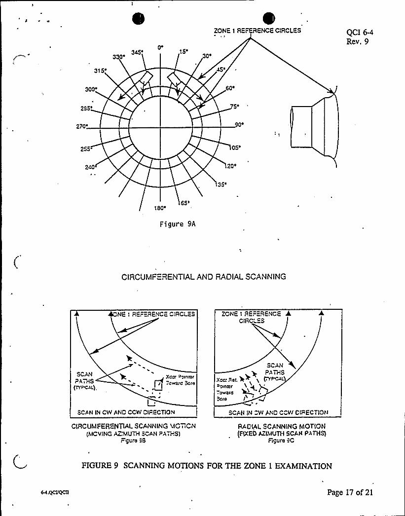
Zgn( - 1
The inner radius Zone 1 shall be scanned in two directions (CW and CCW) from thevessel plate as shown in Figure 9A. Scanning shall be done in a circumferential orradial motion with a minimum overlap of 50% of the transducer element (seeFigures 9B and 9C). The movable pointer on the transducer wedge shall be positionedin the groove marked "CCW" for scanning counter clockwise and "CW" for scanningclockwise. While scanning, the pointer'shall be aimed at the nozzle bore to the extentpractical with the transducer oscillating slightly. The examiner shall referenceFigures 9A, 9B and 9C for transducer orientations,
The scan boundaries extend from the end of the blend radius to a distance of 9 inchesout on the shell wall. The operator shall occasionally rotate the wedge toward the boreaxis to obtain a direct reflection signal from the inner radius as a check to confirmpenetration.
Page 7 of 21
QCI 6-4'Rev. 9
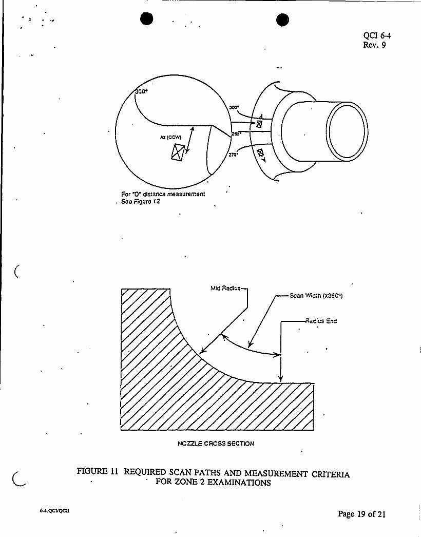
The inner surface of the nozzle shall be scanned from the exterior surface of the nozzleusing the appropriate search unit in two directions: clockwise (CW) andcounterclockwise (CCW) (Figure 11). A circumferential scanning pattern spaced atintervals not exceeding 0.25 in. (3/4 in. overlap) shall be followed around the nozzlebody to obtain full coverage of the inner surface Zone 2.
R
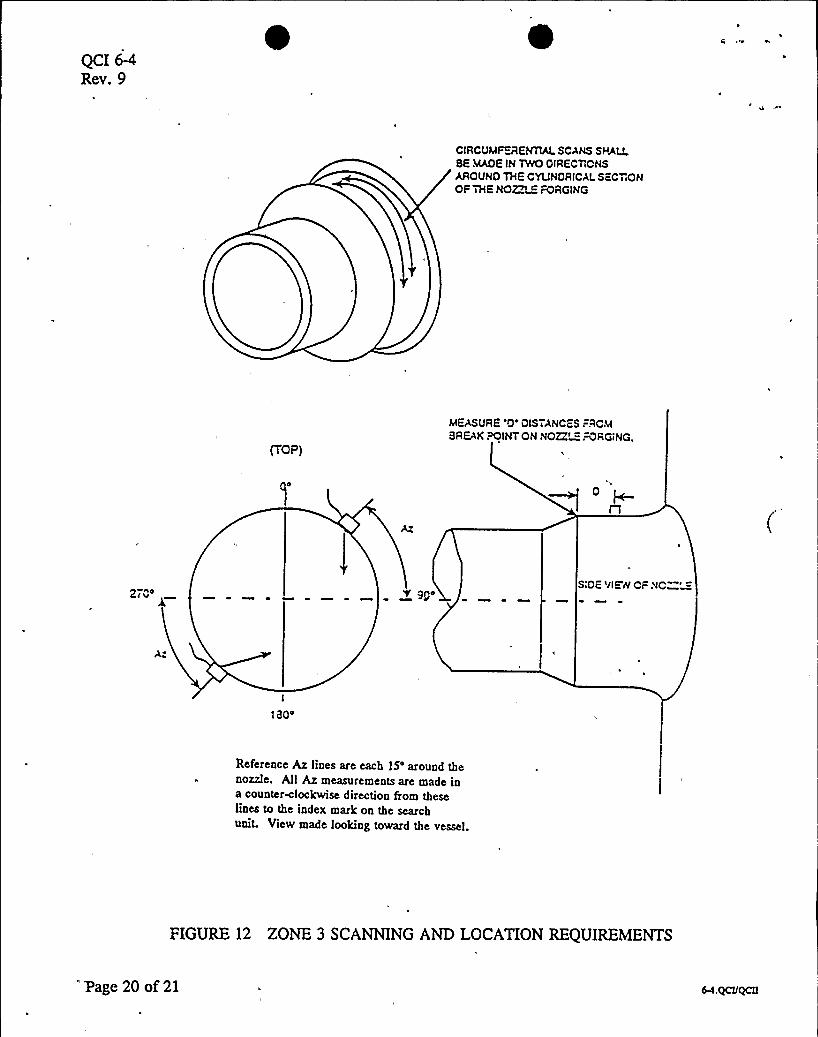
The nozzle forging and the inside bore shall be examined using the cylindrical surfacefor scanning (Figure 12). The scan path of the search unit shall overlap the adjacentscan by a minimum of 50% of the transducer element. The search unit shall be scannedcircumferentially around the nozzle forging so the shear wave insonifies the 360'circumference in both the clockwise and counterclockwise directions.
~ 5.4 The„scanning speed shall not exceed 4 inches.per second.
5.5 ~RIndications in the region of the blend radius which have an amplitude greater than50% FSH at the 2X scanning level and which travel in time position on the CRT shallbe investigated to determine maximum amplitude.
Indications in the region of the blend radius which exceed 25% FSH 'at the primaryreference level (1X) and which travel in time position on the CRT, shall be recorded onthe examination data sheet. Report signal amplitude in % FSH, metal path in inches,search unit direction as clockwise (C%) or counterclockwise (CC%), and search unitposition.
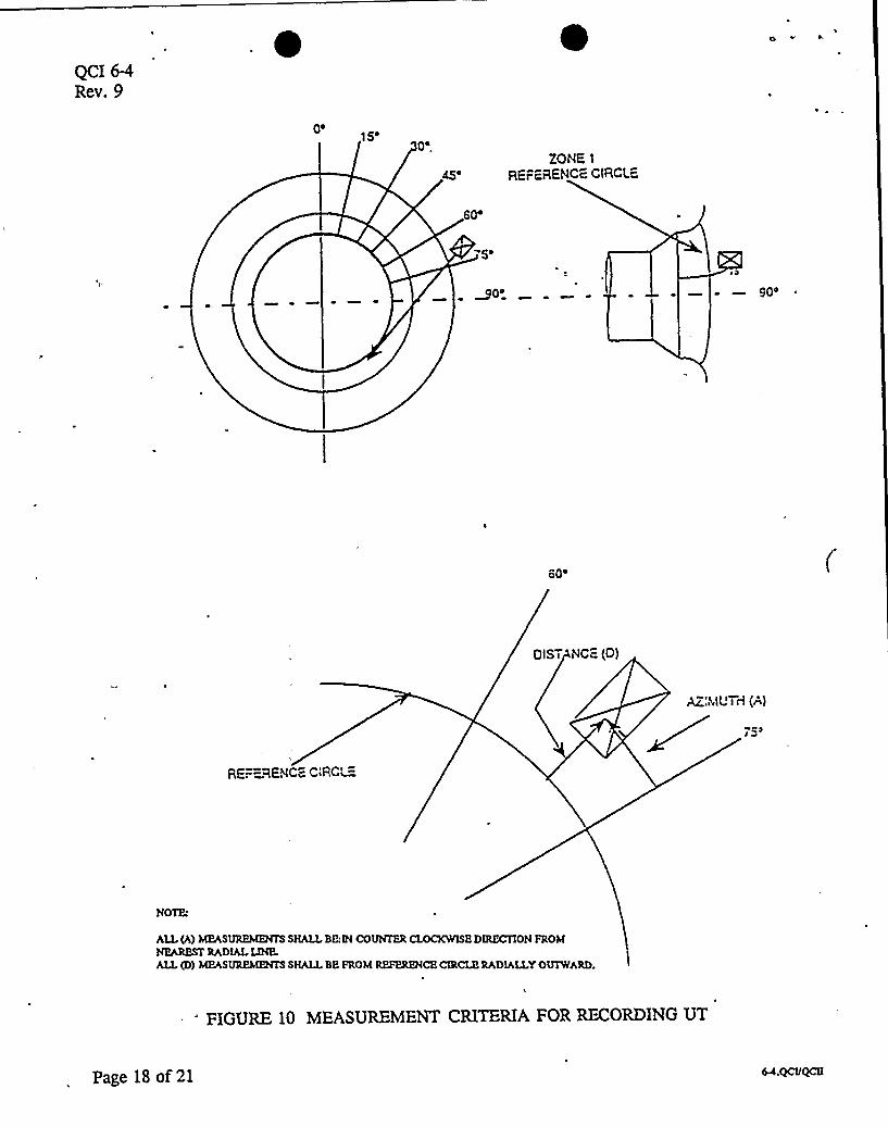
5.6 Rfrn P in frPh ialM uremen
Reference points for physical measurement of azimuth shall be in accordance with thenozzle reference plan shown in Figures 10, 11, and 12.
5.7 DRR55 5
Photos of the CRT display may be taken at th'e option of the Level III'xaminer tofurther document the ultrasonic signal character. Pertinent data shown below shall berecorded on the back of each photo.
Page 8 of,21
0,QCI 6-4Rev. 9
1.2.3.4.5.
Report No.ISI Drawing No.Zone No.Sweep DistanceIndication No.
6.0 DATA PR
6.1 The recorded data shall be reviewed by a level IIIExaminer to determine ifadditionalexamination and/or interpretation is required.
6.2 Recorded indications shall be plotted on a scale no less than quarter size and reviewedby the Level IIIExaminer.
7.7 ~RF EN E
7.1 American Society of Mechanical Engineers Boiler and" Pressure Vessel Code, 1989 noAddenda
7.1.1 Section XI - "Rules for Inservice Inspection of Nuclear Power PlantComponents"
7.1.2 Section V - Nondestructive Examination"
7.2 The Supply System "Program Manual for Qualification and Certification ofExamination, Testing and Inspection Personnel WMC-034"
7.3 Nozzle forging drawings - General Electric/CBI Nuclear
Page 9 of 21
QCI 6-4Rev. 9
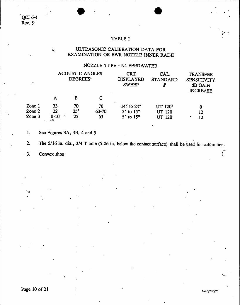
TABLE I
ULTRASONIC CALIBRATIONDATA FOREXAMINATIONOR BWR NOZZLE INNER RADII
NOZZLE TYPE - N4 FEEDWATER
ACOUSTIC ANGLESDEGREES'
B
CRT. CAL TRANSFERDISPLAYED STANDARD,SENSITIVITY
SWEEP ¹ dB GAININCREASE
Zone 1
Zone 2Zone 3
33 70
25'-10
25
7063-70
63
14",'o 24"5" to 15"5" to 15"
UT 120UT 120UT 120
01212
1. See Figures 3A, 3B, 4 and 5
2. The 5/16 in. dia., 3/4 T hole (5.06 in. below the contact surface) shall be used for calibration.
3. Convex shoe
Page 10 of 21
QCI 6-4Rev. 9
NO~ "- ~MINAÃiGNZCiRES
1'! GUR"=
stCE v~Ews
ZONE 1, FLATCONTACT SURFACE2ONE 2. CONVEX CONTACT SURFACE
/I
/
ZONE 3. FLAT CONTACT SURFACE
FIGURE 2 TRANSDUCER %EDGE CONFIGURATIONS
Page 11 of 21
QCI 6-4Rev. 9
~ ~
Vessel Plate
Scan Width
90
Scan StartDimension ~
$0
'
~ ~1g~ g
\ ~~ glt\
~ g
11 ll~ ~
~ g
~ ~
3A. Nominal Entry Point For Sound 8eamFor Zone t
A ~ Skew Angle (Outset)3 = Retracted AngleC = Interceot Angle
Ultrasonic Search UnitAssarnoly wnh Comoound Angle
'
~ ~~ I
'
g\>
y\l\ r
rrr lrrr
rrrrr
38. 8 UND BE.4hl GE ME nY INNCc~ EFOR ZCNE 1
FIGURES 3A and 3B
Page 12 of 21
t ~ ~ 0QCI 6-4Rev. 9
SCANAREA
ScCTIONAL VIEWOF NO~ BOOY
FiGURE 4 SOUNO BEAMGEOMETRY-ZONE 2
FIGURE S SOUND BEAbAGE Ll~iRY. ZONES SF'ICNAL llEW CF
NO@ ' CY':NOE.-.
FIGURES 4 and 5
Page 13 of 21
QCI 6-4Rev. 9
NOZZLE NUMBERLOCATcO ON TAPE
LINES MARKEOON NO&LE SOOY
3Mc
3CC'
304
50'ONE > C:RC'=
RADIALLINES EX-,ENO ATLEcAST2 PAST REr CIRCLE
2P57
X ~I 04
2-
255.05'en
n4
C
/ i
: 804
%4335'BC
C,CM)
FIGURE 6 NOZZLE MARKINGPLAN
Page 14 of 21
V
QCI 6-4Rev. 9
'A SUPPLY SYSTEAI
ULTRASONIC CALIBRATIONSHEET 2one I Cal fbratfon
tRoltcTI NNP-2
CXAMINKAI J. Smfth
ExAMINtRR A ~ 8rown
SERIAL MVMSCR UT 120
1 H ICKN K55
TEMtERA'TURK
6.6"
80
CHART RCCOAOCR TYttl N IA
~RR
AIN IM04
SWE tt
SYSTtM RPY
LEVELI IILEYCLI III
~tIN
INSTRUCTION No 2 OCI 6-4 REVI5IOHR 0
NarisoniZP"~~ZIR ZRZ2599
,zz 9'
9'
2 .25
70ACTUALANCLK
VT IHSTRUIICMTTYttl Sonfc 136
CASLE TYtE RG-1746
16'KNCTH
Soundsafe
SATCH «o. 20922
34643
SHttT NO.R 503
CATER 2 15 95 THEIIMOMKTCR5012 4812
SCRCKN HtlCHT LINEARITY
fOR CONTINUOUS CAIN CONTROL
IN5TRUMENTCALISRATION
tREVIOU5LYtERfCAMEO ON CALISAATIONSHECT NUMSCR
SCRECN HCICHT LINEARITY
fOR 204 STEI'AINCONTROL
AMtLITUOECONTAOL LIHEAIHTY
LITVOKX
I0 100 10 40 TO 40 40 lo 10 20
Low 50 45 KS 34 29 25 20 15
~4 92 0 2 A A Q 10 12 IiHICH 40 4
949 CHANCE
REAOINC X
~ 5 ~ 11
Low 50 to 31 25 20 15 13 10 8 LIMITSX Lt ~ 1l Sl ~ tt SettINI'IIALCAL TIMEI
INSIRIPlKHT SE'TTIHCS RtfLtCIORS AMtLI1UO tXfSH
SYSTEM CALISAATIONSWttt At*CIRC
IN INCHES
flNALCAL TIME>
SCIIE CN OAC tRtSENTATION C*LCHKCKS
COAASE RANCE NI A
COARSE OELAY N(A
RANCE SALES 10
OKLAYCALIS 15 ~ 7
fRCOUKMcv " 2.25CAIN IN RAR 72
DAMtlMC
REJECT - of f
BAILIE
R I
34 NOOK
ft NOOK
lt HOOK
ltMoot
ft NOOK
KII
IS NOOK
IS MOOE
SEARCH UIHTOAIKHTATIOH
SOZ 17.0
AXIAIIK RRRKX N A
09:39 J.S.
WCLOSOR tART5KXAMINEO
0 1 2 1 ~ 4 4 10
AKYIKwtosY LEYEL IHR L ~ 8l'eenfl~ Rll~ ~
fvLL5cRcEMSwtct 10" f14 to 2415M.
CATCI 2) 15 95 RKYIEwto4YR J ~ Jones OATS 2)IS 95
FIGURE 7
Page 15 of 21
'
~ ~
QCI 6-4Rev. 9
WASHINGTONPUBLIC POWER SUPPLY SYSTEM
ULTRASONIC EXAMINATIONDATASHEET - NOZZLE INNER RADIUS Rltonl No.I 1RPU-124
tsoIECTI MNP-2 YSTCMI RPY sI oRAIIUIOHo.5 RPy-JPJOCELCOESCRIt«OH5 Reactor Feedkater Nozzle Inner Radius and Nozzle Sore N4-150-1R, N4-150-NB
5IATCRIALTYtCI Carbon Steel OHC NO.5 ONC HO.I 2 OIIC ko.5 3
5ksTRUcllok No.5 PC 1 6 4
XAMIHCR5 J. 5EIIth
A. SroknI. ETAHOARo Ho.I UT ISO
ACCltTAHCE CRITCRIA5
EYIEION5 9
CVCLI llCVEL5 111
HICKNESS5
o.otscAHOIRESTIOHS5 2 each zone iCM and CCM) ATCI 2 15 95IME S TARSI JP53IMC STot5 1113
ATC5 2 15 95
IMCSTART5 P94P
IMC STot5 1050
L CHEST No.5 504
CLE5 25
L EHlllHo I 5P3
LEI
70'RT
TCMt5 SP t ART TEMt5 SP
AIE5 2 15 95
TWE STAR'55
IME STot5 1129
ART TCMts SU
L CHEST Nou 5P5
LC5 25IHOICATIOH
HUMSCR~OIAR
RCSCRlNCE
45
AZUIUTHICCH)
2.25
DOISTANCt
1.25
AMtL IT Vol5 ESH
90
METALtATH
14.75
SCANICH OR CCNI
CM
315 3.2 3.05 65 15.04 CCM
85
2.6
3.2
2.2
3.0
70
75
17.8
17.7
CCM
CM
I4-30-JR
I4-30-NB
0 - 360 - No oth recordab
0 - 360 - No rec dable ind
e indicatications-
ns-2, 3
5IEVIEI5CO SV LEVELHI5
~ I~ II~ I~
ATE 5,2 I 15 I 95 EVICWEO SY5 ATC5
FIGURE 8
Page 16 of 21
~345'5'0
ZONE I RE~ RENCE CiRCI.ES QCI 6-4Rev. 9
315»300'0295» 5»270'»255
05'0»
35'
So»
65'igure
9A
CIRCUMF:-RENTIALAND RADIALSCANNING
40NE 1 PEPERENCE CIRCLES ZCNE 1 REFERENCE ACIRCLES
SCANPA <.-'.S
p ri Qkr,'1
Xccr ccinmr
rI .c~c Sere
~ ~
L i
SC4N IN CW AND CCW DIRECTION
CIRCUMFEQQJTIAj SCAiVNING AC i iCiV(MCVINGAZlMUirI5C4N PA ir.'S)
r 'gt'N 98
ScbiVP4 i r.'S
Xcc:Bet. W+ y fiYPC L
3cre I
SCAN IN CW biND CCW DIRECTION
RACIALSCANNING MOTION(FIXED AZWUTH SCAN P>THS)
Ftgccs C
FIGURE 9 SCANNING MOTIONS FOR THE ZONE 1 EXAMINATION
Page 17 of 21
QCI 6-4Rev. 9
0'5'4ZONE 1
REFERENCE CIRCLE,
~po 90
60'IST
iVC" (0)
AZ.'LIUirl(A)
RE.-= %ENCE CIRCL=
NOTF.
AU (A) MEASUREMENTS SHALLBBiINCOUNTER CLOCKWISBDIRECTION FROMNEAREST RADIALUNE.ALL(D) MEASUREMENTS SHALLBB FROM REFPJtENCB CIRCLE RADIALLYOUTWARD. I
'IGURE 10 MEASUREMENT CRITERIA FOR RECORDING UT
Page 18 of 21
v
QCI 6-4Rev. 9
AZ(C A)
Far 0 distance measurerhentSee rrgure t2
Mid RadiusScan Width (x3cP~)
acius -nd
HC ZZLE CRCSS SGCTlON
FIGURE 11 REQUIRED SCAN PATHS AND MEASUREMENT CRITERIAFOR ZONE 2 EXAMINATIONS
Page 19 of 21
QCI 6-4Rev. 9
CIRCUMFERENTIALSCANS SHAI'E
MAOE IN TWO OIRECTICNSAROUNO THE CYLINOR(CALScEC c cONOF THE NO~c FORGING
(TOP)
MEASURE '0 QISTANCES FRCMGREAK POINT ON NOZZLeEFORGING
27C4 ggOSIDE 'llEWCF NC
I
I ao.
Reference Az lines are each 15'round thenozzle. All Az measurements are made ina counterclockwise direction from theselines to the index mark on the searchunit. View made looking toward the vessel.
FIGURE 12 ZONE 3 SCANNING AND LOCATION REQUIREMENTS
'Page 20 of 21

.
QCI 6-4Rev. 9
315 330 0 15 30 45
3CO 50
285
270 90
255 05
120
21 19lao
lo5 1 5
Plot of lndlcation(s)for nozzle No.:
Report No.:
FIGURE 13
Scale 1/4
Page 21 of 21

0 f~e ww L
IE
'lk
(