Embed Size (px)
Citation preview
'·
•
•
ATTACHMENT 2
Consumers Power Company Palisades Plant Docket 50-255
INSERVICE TESTING OF PLANT VALVES
Procedure Number EM-09-02
Revision 14
March 13, 1991
122 Pages

• 1.
3.
5 .
• 6.
7.
•
TITLE:
Prepared
George E Schrader
PALISADES NUCLEAR PLANT ENGINEERING MANUAL PROCEDURE Revision and Approval Summary
INSERVICE TESTING OF PLANT VALVES
2. QA Concurrence
01L09L91 NLA ger 10.42 Responsible Individual Date
Q-List Yes No 4. PRC Reviewed Recommended Approval
KAT oner 01Ll6L91 JAMeincke
Proc No EM-09-02 Revision 14 Date Ol/30/91
Date
01LlOL91 Responsible Department Head Date PSL 90-1583 Date
Approved TCN MRN
RDOroz 01Ll6L91 Date
Word Processing Incorporated
01L30[91 COY Date
Periodic Review
George E Schrader 02L01L90 Date
Date
Date
Date
Date

•
•
1.0
2.0
3.0
4.0
5.0
PALISADES NUCLEAR PLANT ENGINEERING MANUAL PROCEDURE
TITLE: INSERVICE TESTING OF PLANT VALVES
PURPOSE
SCOPE .
REFERENCES .
Table of Contents
DEFINITIONS AND RESPONSIBILITIES .
PROCEDURE . . . . . . . . . . . 5. 1 PROGRAM DESCRIPTION . . . . . . . . .
5.1.4 ReQuirements for Relief Requests
Pree No EM-09-02 Revision 14 Page i
5.2 VALVE TEST REQUIREMENTS . . . . . . . . . . . . . . .
1
1
1
4
6 6 6 7 7 8 8
5.2.1 Category A and B Exercise Testing (IWV-3400) 5.2.2 Category C Safety and Relief Valve Testing 5.2.3 Category c Check Valve Testing 5.2.4 Category A Valve Leak Testing 5.2.5 Category D Valves .... . 5.2.6 Rapid Acting Valves ... . 5.2.7 Motor Operated Valve Testing 5.2.8 Remote Position Indication . 5.2.9 Valve Testing Summary ..
5.3 PROGRAM ADMINISTRATION . . . . . . 5.3.1 Test Procedures .... . 5.3.2 Scheduling ....... . 5.3.3 Modified Test Frequencies ..
5.4 NON-CONFORMANCE/CORRECTIVE ACTIONS/DATA . 5.4.6 Trending .
5.5 RECORDS .
6.0 ATTACHMENTS
ATTACHMENTS
Attachment 1, "Valve Reference List in Alpha numeric Order" Attachment 2, "Valve Reference Flow Rates" Attachemnt 3, "Cold Shutdown Testing Basis" Attachment 4, "Relief Request Basis"
10 11 11 11 11 12 12 12 13 14 14 16 16
17

PALISADES NUCLEAR PLANT ENGINEERING MANUAL PROCEDURE
Pree No EM-09-02 Revision 14 Page 1 of 17
• TITLE: INSERVICE TESTING OF PLANT VALVES
----------
•
•
1.0 PURPOSE
1.1 This procedure provides general requirements for the performance and administration of the Inservice Testing Program for ASME Class 1, 2 and 3 valves.
1. 2 This procedure establishes the requirements for the implementing · procedures for inservice testing and evaluation of selected valves.
2.0 SCOPE
2.1 This procedure complies with all requirements of Reference 3.5, ASME Boiler and Pressure Vessel Code, Section XI, Subsection IWV, 1983, Addenda to Summer 1983 with exception of the relief requests contained in Attachment 4.
2.2 The Palisades Plant Inservice Vaive Testing Program will be in effect through the second 120 month interval (1983 thru 1995) and will be updated in accordance with 10CFR50.55a (g).
2.3
3.0
3 .1
3.2
3.3
3.4
3.5
3.6
3.7
3.8
Attachment 1 provides a complete listing of those valves included in this program per the requirements of IWV-1100 and IWV-1200, and specifies the frequency and the procedure to be used for each test.
These valves are those Class 1, 2, and 3 and other valves important to safety (and their actuating and position indicating systems), which are required to perform a specific function in shutting down the reactor to the cold shut down condition or in mitigating the consequences of an accident.
·REFERENCES
Technical Specifications Chapter 4-4.1.1, 4.0.2, 4.0.5, 4.3e, 4.3h, 4.3i, 4.3j, Table 4.3.1, 4.5.2, 4.6.3, 4.8 and 4.9
Final Safety Analysis Report 4.3.9, 6.9.2.2
10CFRS0.55(a)(g)(4)
lOCFRSO~ Appendix J
ASME Boiler and Pressure Vessel Code, Section XI, Subsection IWV, 1983 (S83)
NRC letter dated January 13, 1978
NRC Order dated April 20, 1981 regarding Event V PIV's
Generic Letter No 87-06, "Periodic Verification of Leak Tight Integrity of Pressure Isolation Valves"

PALISADES NUCLEAR PLANT ENGINEERING MANUAL PROCEDURE
TITLE: INSERVICE TESTING OF PLANT VALVES
Pree No EM-09-02 Revision 14 Page 2 of 17
3.9 USNRC IE Bulletin No~ 89-10, 11 Safety Related Motor Operated Valve Testing and Surveillance 11 dated 06/28/89
3.10 Generic Letter No 89-04, 11 Guidance on Developing Atceptable Inservice Testing Programs 11 (AIR A-NL-89-02A and PW04/03/89D)
3.11 Palisades Administrative Procedure 9.22, "Technical Specifications Surveillance Procedure Scheduling and Issue 11
3.12 10CFR50.54(o)
3.13 NRC Information Notice 88-70, Check Valve Inservice Testing Program deficiencies
3.14 CPCo Letter to NRe, Docket 50-255-License DPR-20, Palisades Plant, Confirmation of Conformance with Generic Letter 89-04, (TAC No. 74783)
3.15 . CRl: 11 Control Room Log Sheet No. 1"
3.16 EM-28-02: 11 Preventative Maintenance Program for Check Valves"
3.17 GOP-02: 11 Plant Heatup (Cold Shutdown to Hot Shutdown) 11
3.18 GOP-13: 11 Primary Side Leakage Calculation"
3.19 M0-38: "Auxiliary Feedwater System Pumps, Inservice Testing Procedure"
3.20 PPAC CCS028: "Change Actuator Diaphragm on CV-0951"
3.21 PPAC CVC 081: "Replace Diaphragm on eV-2003, CV-2004, and CV-2005"
3.22 PPAC CVC 107: "Preventative Maintenance of RV-2006"
3.23 M0-7A-1: 11 Emergency Diesel Generator 1-1 (K-6A)"
3.24 M0-7A-2: "Emergency Diesel Generator 1-2 (K-6B)"
3.25 PPAC CVC 110: "Preventative Maintenance of RV-2092"
3.26 PPAe eve 111: "Preventive Maintenance of RV-2098 or RV-2104"
3.27 PPAC eve 112: "Preventative Maintenance of RV-2090/2096/2102"
. 3. 28 PPAC ESS133: 11 Preventative Maintenance to i nspect/repai r/veri fy
3.29
3.30
setpoint of RV-3164"
PPAe ESS134: "Preventative Maintenance of RV-3162"
PPAC ESS135: "Preventative Maihtenance of RV-3165"
3.31 PPAC ESS136: "Preventative Maintenance of RV-3264"
•
•
•
•
•
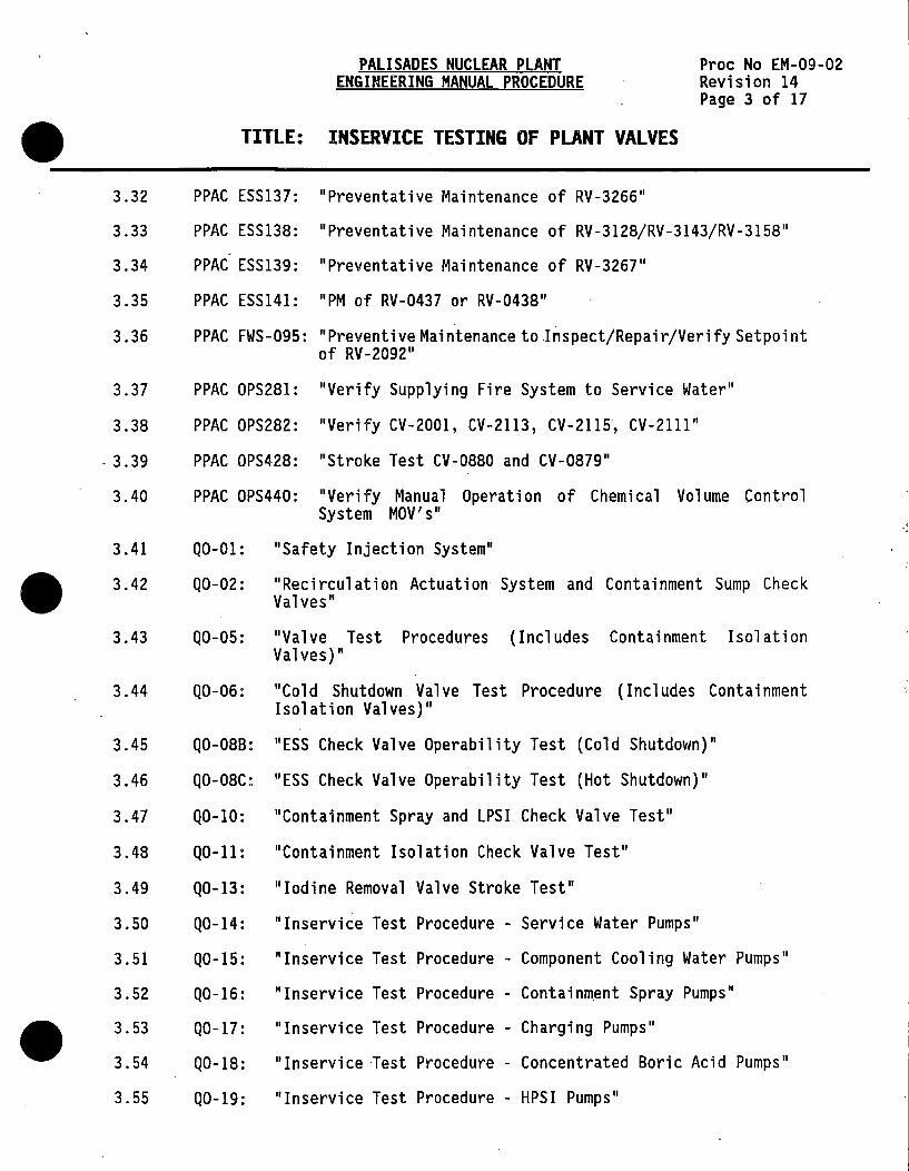
3.32
3.33
3.34
3.35
PALISADES NUCLEAR PLANT ENGINEERING MANUAL PROCEDURE
TITLE: INSERVICE TESTING OF PLANT VALVES
PPAC ESS137: "Preventative Maintenance of RV-3266"
Pree No EM-09-02 Revision 14 Page 3 of 17
PPAC ESS138: "Preventative Maintenance of RV-3128/RV-3143/RV-3158" -
PPAC ESS139: "Preventative Maintenance of RV-3267"
PPAC ESS141: "PM of RV-0437 or RV-0438"
3. 36 PPAC FWS-095: "Preventive Maintenance to .Inspect/Repair/Verify Set point
3.37
3.38
- 3 .39
3.40
of RV-2092"
PPAC OPS281: "Verify Supplying Fire System to Service Water"
PPAC OPS282: "Verify CV-2001, CV-2113, CV-2115, CV-2111"
PPAC OPS428: "Stroke Test CV-0880 and CV-0879"
PPAC OPS440: "Verify Manual Operation of Chemical Volume Control System MOV's"
3.41 Q0-01: "Safety Injection System"
3.42 Q0-02: "Reci rcul ati on Actuation System and Containment Sump Check Valves"
3.43 Q0-05: "Valve Test Procedures (Includes Containment Isolation Valves)"
3.44 Q0-06: "Cold Shutdown Valve Test Procedure (Includes Containment Isolation Valves)"
3.45 Q0-088: "ESS Check Valve Operability Test (Cold Shutdown)"
3.46 Q0-08C: "ESS Check Valve Operability Test (Hot Shutdown)"
3.47 Q0-10: "Containment Spray and LPSI Check Valve Test"
3.48 Q0-11: "Containment Isolation Check Valve Test"
3.49 Q0-13: "Iodine Removal Valve Stroke Test"
3.50 Q0-14: "Inservice Test Procedure - Service Water Pumps"
3.51 Q0-15: "Inservice Test Procedure - Component Cooling Water Pumps"
3.52 Q0-16: "Inservice Test Procedure - Containment Spray Pumps"
3.53
3.54
Q0-17: "Inservice Test Procedure - Charging Pumps"
Q0-18: "Inservice lest Procedure - Concentrated Boric Acid Pumps"
3.55 Q0-19: "Inservice Test Procedure - HPSI Pumps"

PALISADES NUCLEAR PLANT ENGINEERING MANUAL PROCEDURE
TITLE: INSERVICE TESTING OF PLANT VALVES
Proc No EM-09-02 Revision 14 Page 4 of 17
3. 56 Q0-20: "In service Test Procedure - Low Pressure Safety Injection Pump"
3. 57 Q0-21: "Auxiliary Feedwater System Valves In service Test Procedure"
3.58 Q0-24: "Verify Closure of Main Feedwater Check Valves"
3.59 RI-115: "Power Operated Relief Valves"
3.60 RM-29: "Main Steam Safety Valve Setpoint Testing"
3.61 RT-41: "Pressurizer Safety Valves RV-1039, RV-1040, and RV-1041"
3.62 RM-114: "Disassembly, Verification of Disc Motion and Assembly of Safety Injection Tank 12 Inch Check Valves"
3.63 R0-32 Series: "Local Leak Rate Test for Containment Penetrations"
3.64 R0-65: "HPSI/RHPSI Check Valve Test"
3.65 R0-105: "Full Flow Test for Safety Injection Bottle Check Valves CK-3102, CK-3117, CK-3132, and CK-3147"
3.66 RT-88: "Shutdown Cooling/ESS Pump Suction Line Test"
3.67 RT-88A: "CV-3057 and CV-3031 Leak Test"
3.68 SH0-1: "Operator's Shift Items"
3.69 S0-9: "Primary Coolant System Pressure Isolation Check Valves"
3.70 SQ...;11: "Verify Containment Purge and Ventilation Isolation Valves Closed"
3. 71 SOP-2A: "Chemical and Volume Control System Charging and Letdown: Concentrated Boric Acid"
4.0 DEFINITIONS AND RESPONSIBILITIES
4.1 Reference Value - a fixed set of valve operating parameters, (such as stroke time, leakage rate, etc.) which reflect acceptable valve operating characteristics and are determined from the results of a baseline preoperational or inservice test. They shall be readily duplicated and subsequent inservice testing results shall be compared to these reference values.
4.2 Safety Classification - The categorization of a valve as dependent upon its related system and safety related function. The classifications are determined by ASME Section XI, Subsection IWV; ANSI/ANS 51.1 -1983; 10CFR50.2V; 10CFR50.55a(g), Footnote 2; Reg. Guide 1.26.
•
•

PALISADES NUCLEAR PLANT ENGINEERING MANUAL PROCEDURE
Proc No EM-09-02 Revision 14 Page 5 of 17
• TITLE: INSERVICE TESTING OF PLANT VALVES
----------
•
•
4.3 Valve Exercise Test - A test which exercises a valve to the position required for it to fulfill its necessary safety function.
4.4 Full-stroke - the exercising of a valve from full closed to full open using either an actuating signal or, as in the case of check valves, full system flowrate. Full-stroke flow rates for various check valves are listed in the "Valve Reference Flow Rate Table" maintained by the Inservice Inspection Section.
4.5 Partial Stroke - The exercising of a valve in the open direction just enough to verify disc movement off the seat. This is usually performed with check valves using lower than normal system flowrates.
4.6
4.7
4.8
4.9
4.10
Leakage Test - Verification by test of the leak tight integrity of a valve using differential air pressure or system fluid pressure.
Backflow Test - Verification of a check valve's closure ability upon reversal of normal system flow.
Stroke Time - The time interval from initiation of an actuating signal for a valve to open or close, to the end of the actuation cycle.
ISI Coordinator - responsible for the development and administration of the IST program for Plant valves. This person shall also evaluate test results and identify equipment deficiencies to the System Engineer.
System Engineer - Service manager for the system in question who is responsible for the maintenance and operating aspects of the tested equipment.
4.11 Technical Specifications Surveillance Program Administrator (TSSPA) -responsible to oversee scheduling and administrative performance of the required Technical Specifications Surveillance Test.
4.12 Relief Requests - Specific documents requesting exemption from code testing requirement, submitted to the U.S. Nuclear Regulatory Commission (NRC). Upon identification of need, the initial request shall be submitted to the Nuclear Licensing Department who shall review the requests, ask appropriate questions, and prepare the request for relief for submittal to the NRC within 60 days of the identification of need. Identification of need is defined as the point in time a Corrective Action document (DR, ER, AIR, etc.) is initiated or a revision to this procedure is begun.
4.13 Cold Shutdown Testing Basis - Specific documents outlining the reason(s) specific equipment cannot be fully tested during power operations and outlining an alternative test program which meets the requirements of ASME Section XI and Generic Letter 89*04 .

5.0
5.1
5.1.1
5.1.2
. 5.1.3
5.1.4
PALISADES NUCLEAR PLANT ENGINEERING MANUAL PROCEDURE
Proc No EM-09-02 Revision 14 Page 6 of 17
TITLE: INSERVICE TESTING OF PLANT VALVES • PROCEDURE
PROGRAM DESCRIPTION
The Palisades Inservice Valve· Test Program is summarized in the Attachment 1. The valves were selected in accordance with ASME Boiler and Pressure Vessel Code, Section XI, Subsection IWV, 1983 S83, and Generic Letter 89-04, "Guidance on Developing Acceptable Inservi ce Testing Programs". Each valve was assigned as Category A,B,C, or D, or combinations thereof. They were also classified as Active or Passive in accordance with the definitions in ASME Section XI IWV-2100.
Where testing is impractical, pursuant to 10CFR50.55a(g)(iii) and (iv), and as required by Subsection IWV, specific relief shall be requested to perform alternate testing in lieu of the required test. Attachment 4, "Relief Request Basis", contains valves meeting this condition.
IWV-3412 and IWV-3522 requires the owner to specifically identify va 1 ves which cannot be full or part stroke tested during norma 1 operation and are full-stroked during cold shutdown. Attachment 3, "Cold Shutdown Test Basis", provides this information.
Requirements for Relief Requests
a. Relief Requests shall be submitted to the Nuclear Licensing Department upon identification of· need. The Nuclear Licensing Department shall review the submittal requests, ask appropriate questions and prepare the requests for submittal to the United States Nuclear Regulatory Commission.
b. Relief Requests shall contain as a minimum the following elements:
1. Reasons for the impracticality of the required testing.
· 2. A description of the alternate technique used and a summary of the procedure(s) being followed.
3. A description of the method and results of the program to qualify the alternate technique for m~eting the ASME Code.
4. A description of the instrumentation used and the maintenance and calibration of the instruments.
5. A description of the basis used to verify the baseline data has been generated when the component is known to be in good working order, and
6. A description of the basis for the acceptance criteria for the alternate testing and a description of corrective actions to be taken if the acceptance criteria are not met.
•
•

• PALISADES NUCLEAR PLANT
ENGINEERING MANUAL PROCEDURE
TITLE: INSERVICE TESTING OF PLANT VALVES
Proc No EM-09-02 Revision 14 Page 7 of 17
-----------------------------------------------------------------------------
•
•
5.2 VALVE TEST REQUIREMENTS
5.2.1 Category A and B Exercise Testing (IWV-3400) ·
a. Category A and B valves shall be exercised at least once every three months to the position required to fulfill their safety function unless such operation is not pr act i cal during Pl ant operation. If only limited operation is practical during Plant operation, the valve shall be: ·
1. Part-stroked during Plant operations, and
2. Full-stroked during cold shutdowns.
b. Valves that cannot be exercised during Plant operation shall be:
i. Specifically identified in Attachment 3, and
2. · Full-stroke tested during cold shutdowns.
c. Full-stroke exercising during cold shutdown for all valves not full-stroke tested during Plant operation shall be on a frequency determined by the intervals between shutdowns as follows:
1. For intervals of three months or longer, exercise each cold shutdown,
2. For intervals of less than three months, full-stroke testing is not required unless three months have passed since the last shutdown test.
d. For exercising Category A and B active valves, the necessary valve disk movement shall be determined by:
1. Exercising the valve while observing an appropriate indicator which signals the required change of disk position, or
2. Observing indirect evidence, such as changes in system pressure, flow rate, level or temperature, which reflect stem or disk position.
e. Stroke time values for each power operated valve will be specified in the individual test procedure for the valve in question. Stroke times will be measured to the nearest second, for stroke times of 10 seconds or less, or 10% of the specified limitin~ stroke times for times greater than 10 seconds.
f. Reference stroke times and alert limiting values for full-stroke times for testing purposes shall be determined as per Step 5.3.1.

5.2.2
PALISADES NUCLEAR PLANT ENGINEERING MANUAL PROCEDURE
TITLE: INSERVICE TESTING OF PLANT VALVES
Category C Safety and Relief Valve Testing
Pree No EM-09-02 Revision 14 Page 8 of 17
a. Category C Safety and Relief Valves shall have their setpoints verified every five years as follows:
1. The Valve tests shall be distributed over a 60 month period, such that (N/60) x Z valves have been tested each refueling outage (where N equals the number of months from the start of the 60 month period and Z is the number of valves in the program).
b. For safety and relief valve testing, the procedure of PTC25.3 shall be used for setpoint verification. PTC25.3 shall not be used for administrative purposes. Palisades Administrative procedures shall govern items such as personnel and equipment qualifications, procedure formats and test conduct.
5.2.3 Category c Check Valve Testing
a. Category C Check Valves shall be exercised to the position required to fulfill their safety function at least once every three months unless such operation is not practical during plant operation and then as modified below.
b. If only limited operation is practical during Plant operation, at least once every three months each valve shall be:
1. Part stroke exercised during plant operation, and
2. Full-stroke exercised during cold shutdowns.
c. Valves which cannot be exercised during Plant operation shall be:
1. Specifically identified in the fQrm of a cold shutdown test basis, and
2. Full-stroke exercised during cold shutdowns.
d. Full-stroke exercising during cold shutdowns for all valves not full-stroke exercised during Plant operation shall be on a frequency determined by the intervals between shutdowns as follows:
1. For intervals of three months or longer, exercise each cold shutdown.
2. For intervals less than three months, full-stroke exercise is not required unless three months have passed since the last full-stroke exercise.
•
•
•
PALISADES NUCLEAR PLANT ENGINEERING MANUAL PROCEDURE
Proc No EM-09-02 Revision 14 Page 9 of 17
• TITLE: INSERVICE TESTING OF PLANT VALVES
----------
•
•
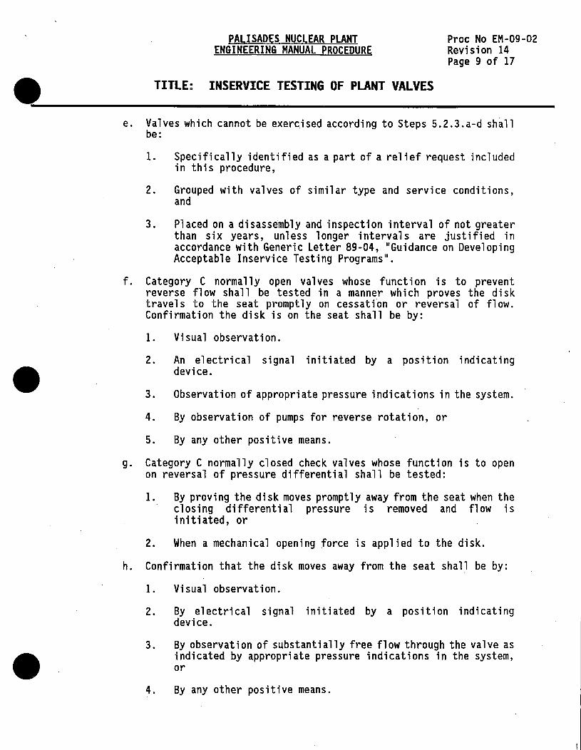
e. Valves which cannot be exercised according to Steps 5.2.3.a-d shall be:
1. Specifically identified as a part of a relief request included in this procedure,
2. Grouped with valves of similar type and service conditions, and
3. Placed on a disassembly and inspection interval of not greater than six years, unless longer intervals are justified in accordance with Generic Letter 89-04, "Guidance on Developing Acceptable Inservice Testing Programs".
f. Category C norma 11 y open valves whose function is to prevent reverse flow shall be tested in a manner which proves the disk travels to the seat promptly on cessation or reversal of flow. Confirmation the disk is on the seat shall be by:
1. Visual observation.
2. An electrical signal initiated by a position indicating device.
3. Observation of appropriate pressure i ndi cations in the system.
4. By observation of pumps for reverse rotation, or
5. By any other positive means.
g. Category C normally closed check valves whose function is to open on reversal of pressure differential shall be tested:
1. By proving the disk moves promptly away from the seat when the closing differential pressure is removed and flow is initiated, or
2. When a mechanical opening force is applied to the disk.
h. Confirmation that the disk moves away from the seat shal_l be by:
1. Visual observation.
2. By electrical signal initiated by a position indicating device.
3. By observation of substantially free flow through the valve as indicated by appropriate pressure indications in the system, or
4. By any other positive means.

PALISADES NUCLEAR PLANT ENGINEERING MANUAL PROCEDURE
TITLE: INSERVICE TESTING OF PLANT VALVES
Proc No EM-09-02 , Revision 14 Page 10 of 17
i. This test may be performed with or without flow through the valve. If the test is without flow through the valve, the following shall occur:
· 1. A mechanical exerciser shall be used to move the disk.
2. The force or torque d~livered to the disk by the exerciser shall, be limited to less than ten percent of the equivalent force or torque represented by the minimum emergency condition pressure differential .acting on the disk, or
3. To 200 percent of the actual observed force or torque required to perform the exercise on the valve when the valve is new and in good operating condition, whichever is less,
4. Except for vacuum breaker valves, the exerciser force or torque delivered to the disk may be equivalent to the desired functional pressure differential force.
j. The disk movement shall be sufficient to prove the dfsk moves freely off the seat.
1. For swing and tilting disk valves, if the test is made by use • of fluid flow through the valve, the pressure differential for equivalent flow shall be no greater than observed during preoperational test.
2. For all types of check valves, it shall be shown that disk movement is sufficient to provide the required accident condition flow rate as listed in the FSAR or Technical Specification. Attachment 2 provides a listing of the full-stroke safety analysis required flows and basis (source) documents for which the valves must be tested.
5.2.4 Category A Valve Leak Testing
a. Category A valves are those for which seat leakage is limited to a specific maximum amount. These valves shall be leakage tested as follows:
1. Category A valves which are part of containment isolation shall be tested in accordance with Federal Regulation 10CFR50, Appendix J, per Relief Request Number 11.
2. Event V pressure isolation valves shall be leak tested in accordance with the requirements of Technical Specifications Table 4.3.1 and IWV-3420.
3. Leakage tests shall be conducted at least once every two years • and shall be performed in accordance with IWV-3423, IWV-3425.

PALISADES NUCLEAR PLANT ENGINEERING MANUAL PROCEDURE
Pree No EM-09-02 Revision 14 Page 11 of 17
• TITLE: INSERVICE TESTING OF PLANT VALVES
-------------
•
•
4. Valves which function in the course of other Plant Operations or other testing of the same interval in a manner which demonstrates functionally adequate leak tightness need not be additionally tested. However, documentation for each valve showing the requirements of IWV are met shall be contained in Attachment I.
However, documentation for each valve showing the requirements of IWV met shall be contained in Attachment I.
5.2.5 Category D Valves
Category D valves are those which are actuated by an energy source capable of only one operation, such as rupture disks or explosively actuated valves. Palisades has no such valves meeting these characteristics in the Inservice Testing Program.
5.2.6 Rapid Acting Valves
a. Valves with stroke times less than 2.0 seconds may be:
I. Documented via a Relief Request, and
2. Treated as Rapid Active Valves.
These valves may have a limiting stroke time of two seconds applied. Upon exceeding two seconds, the valve shall be declared inoperable and corrective action taken per Step 5.4.1.
5.2.7 Motor Operated Valve Testing
a. Palisades motor operated valves contained in the IST Program are stroke time tested in accordance with Step 5.2.1 of this procedure.
b. Additionally, motor operated valve actuators may be tested in accordance with the requirements of NRC IE Bulletin 85-03, "Motor Operated Valve Common Mode Failures During Plant Transients Due to Improper Switch Settings", dated 11/15/85. The program for testing in accordance with this bulletin is controlled by the System Engineering Department.
5.2.8 Remote Position Indication
a. Valves with remote position indicators shall be observed once every two years to verify valve operation is accurately indicated.
b. Valve disc movement is determined by exercising the valve while observing an appropriate indicator which signals the required change of disc position. -

PALISADES NUCLEAR PLANT ENGINEERING MANUAL PROCEDURE
TITLE: INSERVICE TESTING OF PLANT VALVES
Pree No EM-09-02 Revision 14 Page 12 of 17
c. Actual valve movement or observing indirect evidence, such as changes in system pressure, flow rate, level, or temperature, which reflect stem or disc position will be used to verify that remote valve position indicators agree with valve travel direction.
5.2.9 Valve Testing Summary
NOTE:
5.3
5.3.l
a. In summary, the following table outlines the test requirements for all valves contained in the IST Program.
Exercise Valve Leak Test Test Special
Category Function Procedure Procedure Text
A Active 5.2.4 5.2.1 None A Passive 5.2.4 None None B Active None 5.2.1 None c
(RV's & PRV's) Active None 5.2.2 None
c (check valves) Active None 5.2.3 None
D Not applicable for Palisades
No test is required for Category B and C passive valves.
PROGRAM ADMINISTRATION
Test Procedures
Each valve test procedure in this program shall be performed under:
• a Technical Specifications Surveillance Procedure • · an Operating Procedure • a Maintenance Procedure, or • a Periodic Activity, or • an Operations Log
These documents shall be written to comply with this procedure and ASME Section XI, Subsection IWV as amended by the Technical Specifications. A single procedure may be used for multiple pieces of equipment, however applicable data, precautions, operating requirements, setpoint, etc., shall be addressed for each piece of equipment.
a. The ISi Coordinator shall establish reference values for each valve in order to trend changes in the valve's operating condition. The
•
•
reference stroke time shall be the expected stroke time based on • the past historical operating data for each valve. The stroke time reference value for each valve shall be maintained by the ISi Engineer in the Valve Inservice Testing Record.

PALISADES NUCLEAR PLANT ENGINEERING MANUAL PROCEDURE
Proc No EM-09-02 Revision 14 Page 13 of 17
tt _____________ 1_1_1_LE_= ___ 1N_s_E_Rv_1_c_E_T_E_s1_1_N_G_o_F __ PLAN---T-v_A_Lv_E_s ____________ __
• 5.3.2
•
b. The ISI Coordinator shall establish alert limits based upon the reference value. For valves which trend up and exceed these values, the ISI Coordinator shall coordinate with the System Engineer to take corrective action in accordance with Step 5.4.2b. The Alert Ranges shall be established for each valve as follows:
1. The reference value shall be increased by 25 percent for valves with stroke times greater than ten seconds.
2. The reference value sha 11 be increased by 50 percent for valves with stroke times equal to or less than ten seconds, except for Rapid Acting Valves. Rapid Acting Valves are addressed in Step 5.2.6.
c. The ISi Coordinator shall establish limiting stroke times for each valve based on the reference values which will be set at a value that will most likely indicate valve degradation. These limiting stroke times shall be established as follows:
1.. For valves with reference value stroke times of 10 seconds or less, the reference value shall be increased by 75% to obtain the limiting stroke time .
2. For valves with reference value stroke times of greater than 10 seconds, the reference value shall be increased by 50% to obtain the limiting stroke time.
Scheduling
a. The basic scheduling mechanism. for Technical Specifications Surveillance Procedures shall be in accordance with Palisades Administrative Procedure 9.22, "Scheduling of Surveillance Procedures". These will be administered by the Technical Specification Surveillance Procedure Program Coordinator (TSSPA).
b. Other types of procedures and documents used to obtain the data required by this program shall be scheduled in accordance with department procedures.
c. Unless otherwise specified, each inservice test surveillance requirement shall be performed within the specified time interval with (see Relief Request 23):
1. A maximum allowable extension not to exceed 25% of the surveillance interval, and
2. A total maximum combined interval time for any three consecutive surveillance intervals not to exceed 3.25 times the specified surveillance interval.

PALISADES NUCLEAR PLANT ENGINEERING MANUAL PROCEDURE
TITLE: INSERVICE TESTING OF PLANT VALVES
5.3.3 Modified Test Frequencies
Pree No EM-09-02 Revision 14 Page 14 of 17
It is the responsibility of the ISi Engineer to notify the TSSPA of any change in the testing frequency for a particular piece of equipment. This change shall be documented in the test record.
5.4 NON-CONFORMANCE/CORRECTIVE ACTIONS/DATA EVALUATION
5.4.1 If any valve fails to exhibit the required change of stem or disk position, corrective action shall be taken as follows:
a. The shift Supervisor shall be immediately notified.
b. The Shift Supervisor shall immediately declare the nonconforming piece of equipment inoperable.
c. The Shift Supervisor shall review the Technical Specifications for applicable Limiting Conditions of Operation and Action Statements.
d. Corrective action shall be immediately initiated.
e. Repairs shall be made before power operations for valves tested only during nonoperating conditions and,
f. A retest showing acceptable operation shall be conducted before a nonconforming valve is declared operable.
5.4.2 For Category A & B Exercise Testing, two evaluations are performed on the "As Received" stroke time:
a. The Shift Supervisor compares the recorded stroke time with the limiting value. This initial evaluation shall ensure the valves are capable of performing their function. If the valve fails to stroke in the required time or exhibits other unsatisfactory actions, the following actions shall be taken: ·
1. The affected valve shall be declared inoperable by the Shift Supervisor.
2. The Shift Supervisor shall review the Technical Specifications for applicable Limiting Conditions of Operation and Action Statements.
3. Corrective action shall be. immediately initiated.
4. The valve operability status and associated corrective action documents sha 11 be noted on the Acceptance Criteria and Operability Sheet of the test procedure, and
5. The test procedure shall continue to be routed according to the Issue and Routing Sheet.
•
•
•
PALISADES NUCLEAR PLANT ENGINEERING MANUAL PROCEDURE
Proc No EM-09-02 Revision 14 Page 15 of 17
• TITLE: INSERVICE TESTING OF PLANT VALVES
-------------
•
•
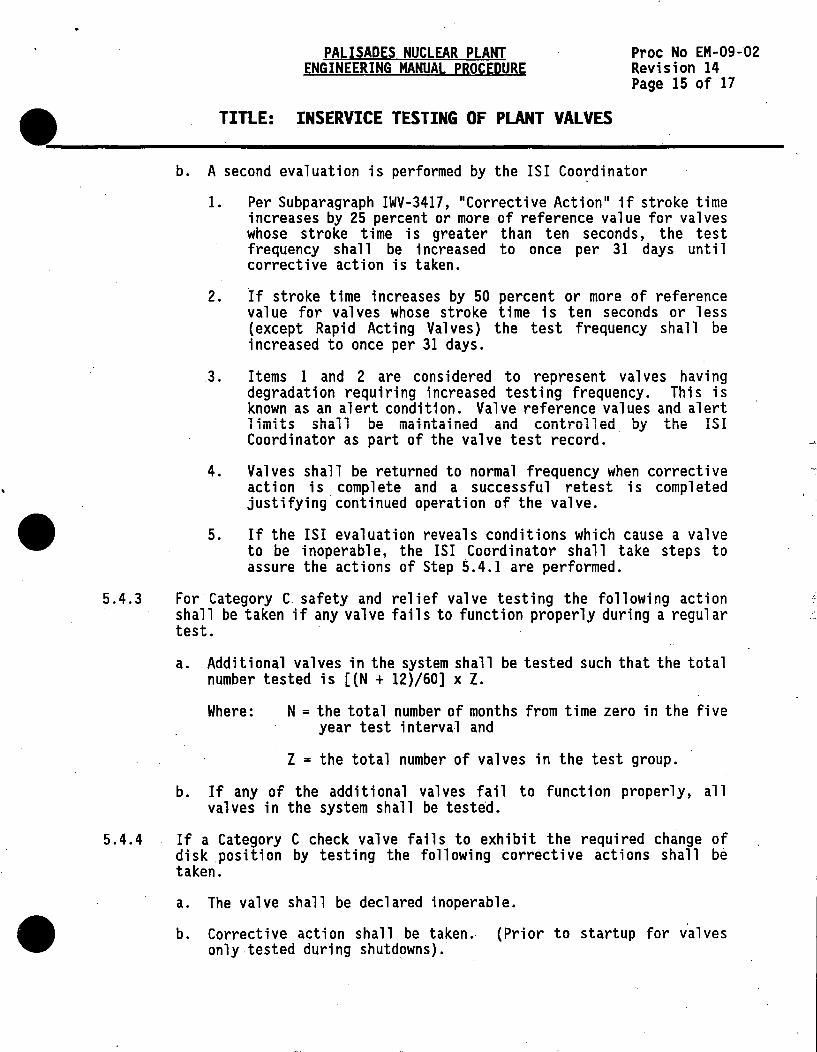
b. A second evaluation is performed by the ISi Coo~dinator
I. Per Subparagraph IWV-3417, "Corrective Action" if stroke time increases by 25 percent or more of reference value for valves whose stroke time is greater than ten seconds, the test frequency shall be increased to once per 31 days until corrective action is taken.
2. ·If stroke time increases by 50 percent or more of reference va 1 ue for va 1 ves whose stroke ti me is ten seconds or 1 ess (except Rapid Acting Valves) the test frequency shall be increased to once per 31 days .
. 3. Items I and 2 are considered to represent valves having degradation requiring increased testing frequency. This is known as an alert condition. Valve reference values and alert limits shall be maintained and controlled by the ISi Coordinator as part of the valve test record. ·
4. Valves shall be returned to normal frequency when corrective action is complete and a successful retest is completed justifying continued operation of the valve .
5. If the ISi evaluation reveals conditions which cause a valve to be inoperable, the ISi Coordinator shall take steps to assure the actions of Step 5.4.1 are performed.
5.4.3 For Category C safety and relief valve testing the following action shall be taken if any valve fails to function properly during a regular test.
5.4.4
a. Additional valves in the system shall be tested such that the total number tested is [(N + 12)/60] x Z.
Where: N = the total number of months from time zero in the five year test interval and
Z = the total number of valves in the test group.
b. If any of the additional valves fail to function properly, all valves in the system shall be tested.
If a Category C check valve fails to exhibit the required change of disk position by testing the following corrective actions shall be taken.
a. The valve shall be declared inoperable .
b. Corrective action shall be taken.. (Prior to startup for valves only tested during shutdowns).

5.4.5
5.4.6
PALISADES NUCLEAR PLANT ENGINEERING MANUAL PROCEDURE
TITLE: INSERVICE TESTING OF PLANT VALVES
· Proc No EM-09-02 Revision 14 Page 16 of 17
c. A successful retest shall be performed prior to declaring the valve operable.
d. For check valves disassembled and inspected in accordance with Step 5.2.3e, any failure of the valve to full-stroke or if there is binding or failure of intervals, the remaining valves in the group shall be disassembled, inspected and manually full-stroked during the same outage. This requirement is from Generic Letter 89*04, Position #2.
For Category A valve leak testing, the following criteria shall apply for corrective action.
a. Leakage rates which reduce the margin between baseline and maximum permissible rate by 50% shall be placed on 31 day testing frequency until corrective action is taken and a successful retest is completed.
b. For leakage trends which show the maximum permissible leak rate wi 11 be exceeded by more than 10% at the next scheduled test interval the valve shall be replaced or repaired and a successful retest completed.
Trending
•
The ISI coordinator shall be responsible to record and trend test data • in order to predict when valve depredation will exceed limits. The goal of this trending is to maintain valve function and to perform needed repairs during convenient times prior to the valve becoming inoperable. Trending shall normally b~ accomplished with the aid of personal computers and standard data management software available throughtout the industry.
The ISI Coordinator shall maintain a status summary of all valves tested in the IST program. This status summary shall be available for review by auditors and plant personnel. This summary may also be distributed as appropriate. The status summary format is presently under development.
5.5 RECORDS
5.5.1 Valve records shall consist of the following documents:
a. Technical Specifications Surveillance Procedures
b. Valve Inservice Testing Trending Records
c. Applicable Work Orders
d. Applicable corrective action documents
e. Valve Status Summary Report (under development)
These documents shall be maintained as lifetime Plant records. These documents should be filed under the Uni form Filing Index numbers 22-22-03. •

PALISADES NUCLEAR PLANT ENGINEERING MANUAL PROCEDURE
Proc No EM-09-02 Revision 14 Page 17 of 17
~-------------T-I_T_LE_: __ 1_N_s_ER_v_1_c_E_T_E_s1_1_N_6_o_F_P_LAN ___ 1_v_A_Lv_E_s ____________ __
6.0 ATTACHMENTS
6.1 Attachment 1, "Valve Reference List in Alpha Numeric Order"
6.2 Attachment 2, "Valve Reference Flow Rates"
6.3 Attachment 3, "Cold Shutdown Testing Basis"
6.4 Attachment 4, "Relief Request Basis"
•
•
•
•
•
------------------------------
PALISADES NUCLEAR PLANT INSERVICE TEST PROGRAM
VALVE TEST TABLE
Proc No EM-09-02 Attachment 1 Revision 14 Page 1 of 1
This table is maintained as an "Engineering Aid" in accordance with Administrative Procedure 10.42. See the ISi Section for details .

•
•
•
PALISADES NUCLEAR PLANT VALVE REFERENCE FLOW RATE
Proc No EM-09-02 Attachment 2 Revision 14 Page 1 of 1
This table is maintained as an "Engineering Aid" in accordance with Administrative Procedure 10.42. See the ISI Section for details .
•
•
•
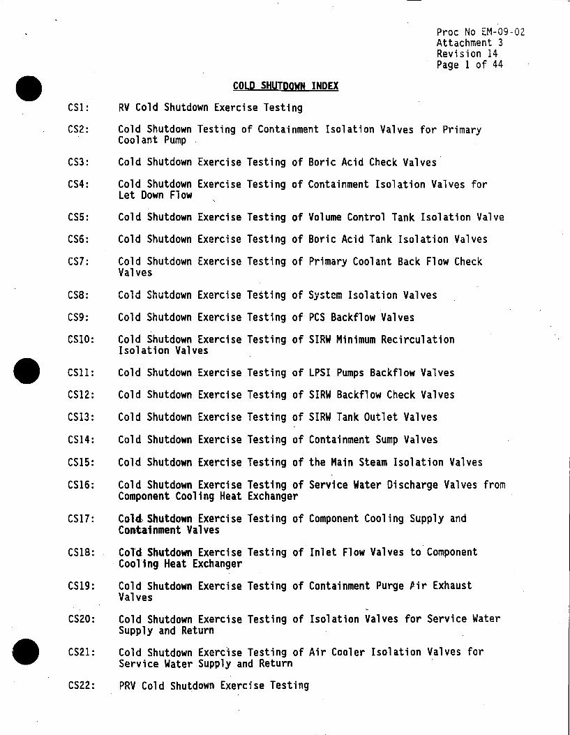
CSl:
CS2:
CS3:
CS4:
CSS:
CS6:
CS7:
CS8:
CS9:
CSlO:
CSll:
COLD SHUTDOWN INDEX
RV Cold Shutdown Exercise Testing
Proc No EM-09-02 Attachment 3 Revision 14 Page 1 of 44
Cold Shutdown Testing of Containment Isolation Valves for Primary Coolant Pump
Cold Shutdown Exercise Testing of Boric Acid Check Valves·
Cold Shutdown Exercise Testing of Containment Isolation Valves for Let Down Flow
Cold Shutdown Exercise Testing of Volume Control Tank Isolation Valve
Cold Shutdown Exercise Testing of Boric Acid Tank Isolation Valves
Cold Shutdown Exercise Testing of Primary Coolant Back Flow Check Valves
Cold Shutdown Exercise Testing of System Isolation Valves
Cold Shutdown Exercise Testing of PCS Backflow Valves
Cold Shutdown Exercise Testing of SIRW Minimum Recirculation Isolation Valves
Cold Shutdown Exercise Testing of LPSI Pumps Backflow Valves
CS12: Cold Shutdown Exercise Testing of SIRW Backflow Check Valves
CS13: Cold Shutdown Exercise Testing of SIRW Tank Outlet Valves
CS14: Cold Shutdown Exercise Testing of Containment Sump Valves
CSIS: Cold Shutdown Exercise Testing of the Main Steam Isolation Valves
CS16: Cold Shutdown Exercise Testing of Service Water Discharge Valves from Component Cooling Heat Exchanger
CS17: Cold, Shutdown Exercise Testing of Component Cooling Supply and Conta·inment Valves
CS18: Col'd Shutdown Exercise Testing of Inlet Flow Valves to Component Cooling Heat Exchanger
CS19: Cold Shutdown Exercise Testing of Containment Purge Pir Exhaust Valves
CS20: Cold Shutdown Exercise Testing of Isolation Valves for Service Water Supply and Return
CS21: Cold Shutdown Exercise Testing of Air Cooler Isolation Valves for Service Water Supply and Return
CS22: PRY Cold Shutdown Exercise Testing

Pree No EM-09-02 Attachment 3 Revision 14 Page 2 of 44
CS23: Cold Shutdown Testing of Main Feedwater Regulating and Bypass Valves
CS24: Cold Shutdown Testing of Primary Coolant System Block Valves
CS25: Cold Shutdown Testing of Chemical and Volume Control SIRW Tank Motor Operated Valve
CS26: Cold Shutdown Testing of Chemical and Volume Control Borit Acid Injection Check Valves
CS27: Cold Shutdown Testing of LPSI and HPSI Check Valves
CS28: Cold Shutdown Testing of CCW Heat Exchanger Service Water Flow Control Valves
•
•
•

•
•
•
SYSTEM:
VALVES:
CATEGORY:
COLD SHUTDOWN TESTING BASIS NUMBER 1
Primary Coolant System (M-201-2)
Proc No EM-09-02 Attachment 3 Revision 14 P~ge 3 of 44
PRV-1067, PRV-1068, PRV-1069, PRV-1070, PRV-1071 AND PRV-1072
B CLASS: 1
FUNCTION:·
1. Reactor Coolant Pressure Boundary Isolation Valves.
2. Reactor Vessel vent valves, Primary Coolant System high point vent valves (from Pressurizer), added per NUREG 0737.
TEST REQUIREMENT:
1. IWV-3411; Test Frequency - Exercise at least once every three months.
BASIS:
Exercising of these valves duririg operation breaches the Primary Coolant System and Reactor Coolant Pressure Boundary. This creates an inter-system LOCA. ·
ALTERNATIVE TESTING:
Exercise during cold shutdowns per Surveillance Procedure Q0-6, but not necessarily more frequently than once each quarter.
VERIFICATION METHOD:
The performance of these valves shall be determined by recording and trending stroke time values in the open and close direction per the instructions of Q0-6. Valve position is determined by observing the valve position indicating lights located in the Control Room.
CORRECTIVE ACTION:
Should either valve fail to meet the stroke time acceptance criteria, corrective action per procedure EM-09-02 Step 5.4.1 shall be taken .

COLD SHUTDOWN TESTING BASIS NUMBER 2
Proc No EM-09-02 Attachment 3 Revision 14 Page 4 of 44
SYSTEM: Chemical and Volume Control CM-202-ll
VALVES: CV-2083, CV-2099
CATEGORY:
FUNCTION:
A CLASS: 2
Containment isolation valve for primary coolant pump seal controlled bleedoff line to volume control tank.
TEST REQUIREMENT:
1. IWV-3411; Test Frequency - Exercise at least once every three months.
COLD SHUTDOWN BASIS:
Shutting this valve during primary coolant pump operation (i.e., any hot plant condition} stops pump seal leakoff flow. Since this flow provides both seal lubrication and cooling, interruption can cause seal failure and will cause a relief valve to lift, resulting in the unnecessary loss of primary coolant as radioactive waste.
ALTERNATIVE TESTING:
Exercise during cold shutdowns per Surveillance Procedure Q0-06, but not necessarily more frequently than once each quarter.
VERIFICATION METHOD:
Operability of these valves shall be determined by observing and recording the stroke time from the open to closed position. Valve position is determined by observing the valve position and indicating lights located on control panel EC-11.
CORRECTIVE ACTION:
Should either of these valves fail to meet the stroke time or leak rate requirements, corrective action as outlined in Procedure Step 5.4.1 shall be taken.
•
•
•

•
•
•
SYSTEM:
COLD SHUTDOWN TESTING BASIS NUMBER 3
Chemical and Volume Control {M-202-IAl
Proc No EM-09-02 Attachment 3 Revision 14 Page 5 of 44
VALVES: CK-CVC2138, CK-CVC2139
CATEGORY:
FUNCTION:
c CLASS: 2
Prevent backflow of Boric Acid Pump Discharge into the concentrated boric acid tanks and also provide a flow path for boric acid injection to the charging pump suctions.
TEST REQUIREMENT:
1. IWV-3521; Test Frequency - Exercise at least once every three months.
COLD SHUTDOWN BASIS~
These valves only open when there is flow of concentrated boric acid. Opening any of these valves during normal plant operation would result in a reactivity excursion from the injection of boric acid into the PCS. The resulting reactor power/PCS temperature excursion could result in a reactor trip. During hot shutdown, since significant PCS boration does not occur, exercising these valves would result in the unnecessary generation of large quantities of radioactive waste, especially late in core life.
ALTERNATIVE TESTING:
Exercise to the full open position during cold shutdowns per System Operating Procedure 2A, Attachment 2. Valve Closure is verified quarterly per Inservice Test Procedure Q0-18, "Boric Acid Pumps".
VERIFICATION METHOD:
Operability of these valves shall be determined by observing and recording pump flow rates as indicated on Charging Pump Flow Indicator FI-0212. Check valves CK-CVC2138 and CK-CVC2139 shall be able to pass the flow required by the Charging Pumps.
Verification of leak tightness is documented by an acceptable flow test during the performance ~f Q0-18. ·

CORRECTIVE ACTION:
COLD SHUTDOWN TESTING BASIS NUMBER 3 (Continued}
Proc No EM-09-02 Attachment 3 Revision 14 Page 6 of 44
Should either valve fail to meet the flow requirements of CL 2.2 or the leakage limits of Q0-18 corrective action as outlined in Procedure · Step 5.4.1 shall be taken.
•
•
•
• SYSTEM:
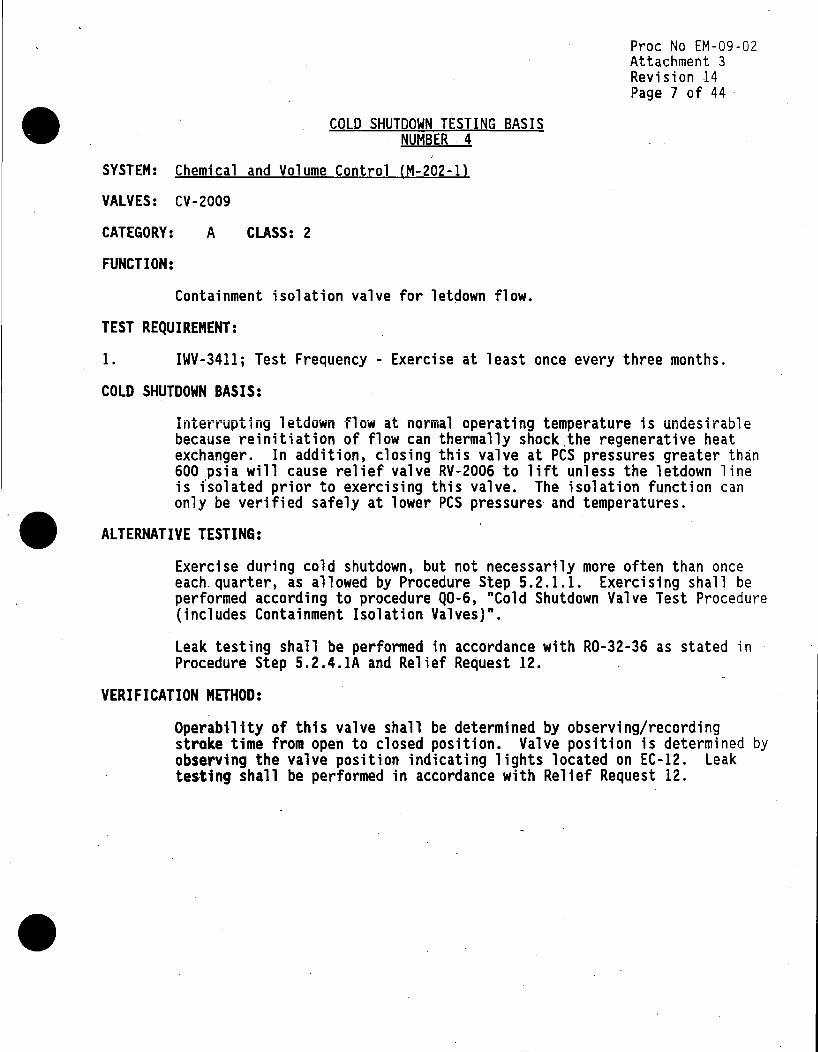
COLD SHUTDOWN TESTING BASIS NUMBER ~ 4
Chemical and Volume Control (M-202-ll
Pree No EM-09-02 Attachment 3 Revision 14 Page 7 of 44 ·
VALVES: CV-2009
CATEGORY: A CLASS: 2
FUNCTION:
Containment isolation valve for letdown flow.
TEST REQUIREMENT:
1. IWV-3411; Test Frequency - Exercise at least once every three months.
COLD SHUTDOWN BASIS:
Interrupting letdown flow at normal operating temperature is undesirable because reinitiation of flow can thermally shock.the regenerative heat exchanger. In addition, closing this valve at PCS pressures greater than 600 psia will cause relief valve RV-2006 to lift unless the letdown line is i·solated prior to exercising this valve. The isolation function can only be verified safely at lower PCS pressures and temperatures.
• ALTERNATIVE TESTING:
•
Exercise during cold shutdown, but not necessarily more often than once each_ quarter, as allowed by Procedure Step 5.2.1.1. Exercising shall be performed according to procedure Q0-6, "Cold Shutdown Valve Test Procedure (includes Containment Isolation Valves)".
Leak testing shall be performed in accordance with R0-32-36 as stated in Procedure Step 5.2.4.lA and Relief Request 12.
VERIFICATION METHOD:
Operability of this valve shall be determined by observing/recording stroke time from open to closed position. Valve position is determined by observing the valve position indicating lights located on EC-12. Leak testing shall be performed in accordance with Relief Request 12 .

CORRECTIVE ACTJON:
COLD SHUTDOWN TESTING BASIS NUMBER 4 (Continued)
Proc No EM-09-02 Attachment 3 Revision 14 Page 8 of 44
Should this valve fail to meet the stroke time or leak rate requirements, corrective action as outlined in Procedure Step 5.4.1 shall be taken .
•
•
•

• SYSTEM:
COLD SHUTDOWN TESTING BASIS NUMBER 5
Chemical and Volume Control (M-202-lA)
Proc No EM-09-02 Attachment 3 Revision 14 Page 9 of 44
VALVES: M0-2087
CATEGORY:
FUNCTION:
B CLASS: 2
Volume Control Tank outlet isolation valve. Valve Closes on safety injection signal so that full charging pump flow comes from the concentrated Boric Acid Tanks or SIRW tank.
TEST REQUIREMENT:
1. IWV-3411; Test Frequency - Exercise at least once every three months.
COLD SHUTDOWN BASIS:
Exercising this valve requires interruption of charging and letdown flow. In this condition with the Primary Coolant System hot, the regenerative heat exchanger would be thermally shocked when the charging/letdown flow is reestablished.
• ALTERNATIVE TESTING:
•
Exercise during cold shutdowns per Surveillance Procedure Q0-06, but not necessarily more frequently than once each quarter.
VERIFICATION METHOD:
Operability of this valve shall be determined by observing/recording stroke time from open to closed position. Valve position is determined by observing valve position indicating lights located on EC-12. Leak rate closure capability shall be considered acceptable when the acceptance criteria of Checklist 2.2 are met.
CORRECTIVE ACTION:
Should this valve fail to meet the stroke time or closure rate requirements, corrective action as outlined in Procedure Step 5.4.1 shall be taken .

Pree No EM-09-02 Attachment 3 Revision 14 Page 10 of 44
COLD SHUTDOWN TESTING BASIS NUMBER 6 • SYSTEM: Chemical and Volume Control (M-202-lAl
VALVES: M0-2169, M0-2170
CATEGORY: B CLASS: 2
FUNCTION:
1. Valves open on safety injection signal to provide the concentrated boric acid gravity feed path to the charging pump suctions.
2. Valves isolate to maintain Boric Acid Tank levels.
TEST REQUIREMENT:
1. IWV-3411; Test Frequency - Exercise at least once every three months.
BASIS:
Opening these valves during normal plant operation would result in a significant reactivity change from the injection of concentrated boric acid into the PCS. The resulting reactor power/PCS temperature excursion could cause a reactor trip. During hot shutdown, since significant PCS • boration does not occur, exercising these valves can result in the unnecessary generation of large quantities of radioactive waste, especially late in core life.
ALTERNATIVE TESTING:
Exercise during cold shutdown, but not necessarily more frequently than once each quarter, as allowed by Procedure Step 5.2.1.1. Exercising shall be performed according to procedure Q0-6, "Cold Shutdown Valve Test Procedure (includes Containment Isolation Valves)".
VERIFICATION METHOD:
Operability of these valves shall be determined by observing/recording stroke time from close to open position. Valve position is determined by observing valve position indicating lights on panel EC-12. Closure verification is provided by recording Concentrated Boric Acid Tank levels per LIA-0206 and LIA-0208 per Operations log.
•

•
•
•
CORRECTIVE ACTION:
COLD SHUTDOWN TESTING BASIS NUMBER 6 (Continued)
Proc No EM-09-02 Attachment 3 Revision 14 Page 11 of 44
Should these valves fail to meet the stroke time or closure requirements, corrective action as outlined in Procedure Step 5.4.l shall be taken .
Proc No EM-09-02 Attachment 3 Revision 14
COLD SHUTDOWN TESTING BASIS NUMBER 7
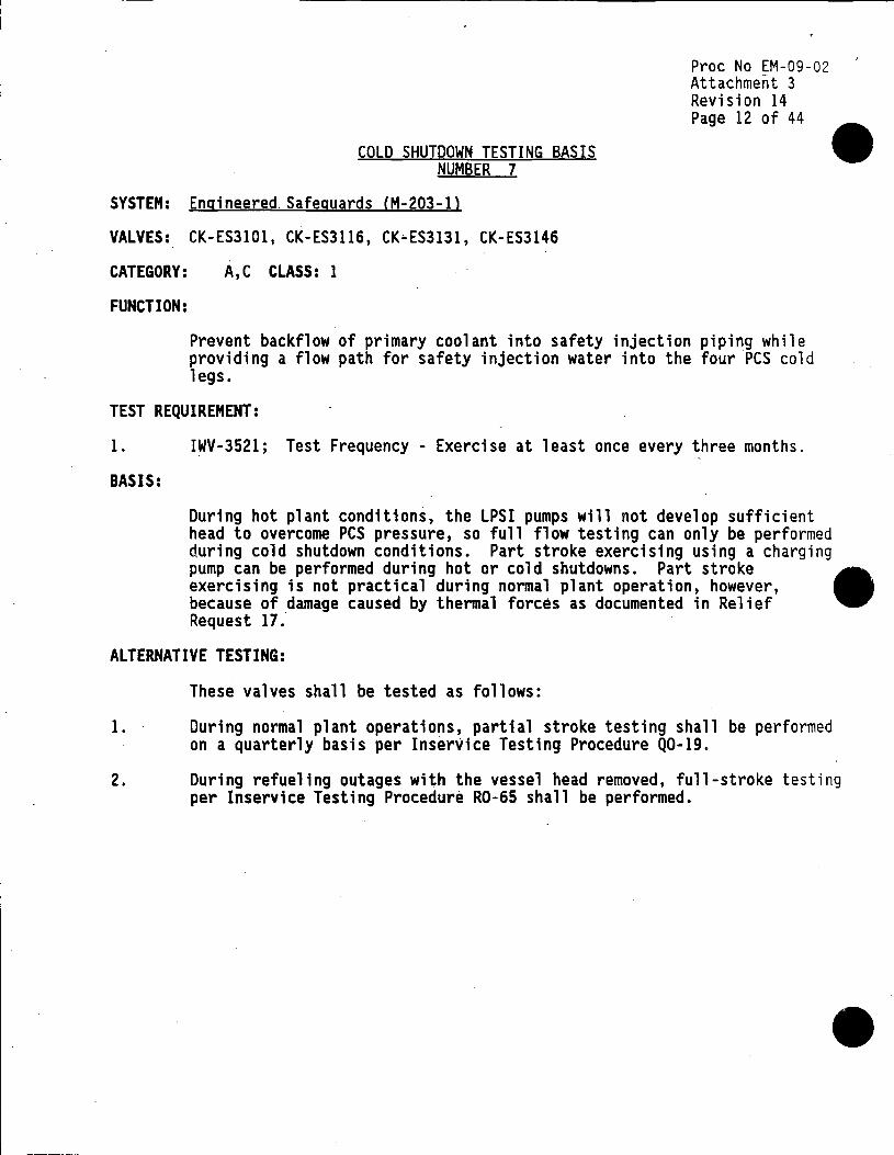
Page 12 of 44
• SYSTEM: Engineered. Safeguards (M-203-ll
VALVES: CK-ES3101, CK-ES3116, CK~ES3131, CK-ES3146
CATEGORY:
FUNCTION:
A,C CLASS: 1
Prevent backflow of primary coolant into safety injection piping while providing a flow path for safety injection water into the four PCS cold legs.
TEST REQUIREMENT:
1. IWV-3521; Test Frequency - Exercise at least once every three months.
BASIS:
During hot plant conditions, the LPSI pumps will not develop sufficient head to overcome PCS pressure, so full flow testing can only be performed during cold shutdown conditions. Part stroke exercising using a charging pump can be performed during hot or cold shutdowns. Part stroke • exercising is not practical during normal plant operation, however, because of damage caused by thermal forces as documented in Relief Request 17.
ALTERNATIVE TESTING:
These valves shall be tested as follows:
1. During normal plant operations, partial stroke testing shall be performed on a quarterly basis per Inservice Testing Procedure Q0-19.
2. During refueling outages with the vessel head removed, full-stroke testing per Inservice Testing Procedure R0-65 shall be performed.
•

•
•
•
---------- - -----
VERIFICATION METHOD:
COLD SHUTDOWN TESTING BASIS NUMBER 7 (Continued)
Proc No EM-09-02 Attachment 3 Revision 14 Page 13 of 44
Verification_ of valve performance shall occur through the monitoring of degradation via cold shutdown procedure QO-SB. This test verifies the ability of these valves to pass approximately 1500 gpm flow.
~erification of valve leakage shall occur via the performance of S0-9. · This procedure invokes an acceptance criteria of less than 1 gpm leakage.
CORRECTIVE ACTION:
Should these valves fail to meet their stroke or leak requirements, corrective action as outlined in Procedure Step 5.4.1 shall be taken .

COLD SHUTDOWN TESTING BASIS NUMBER 8
SYSTEM: Engineered Safeguards (M-203-2)
VALVES: CV-3001, .CV-3002
CATEGORY: B CLASS: 2
FUNCTION:
Pree No EM-09-02 Attachment 3 Revision 14 Page 14 of 44
Serve as system isolation valves which open during accident conditions to initiate containment spray.
TEST REQUIREMENT:
.,
1. IWV-3411; Test Frequency - Exercise at least once per every three months.
BASIS:
Exercising these valves during normal operation may result in draining the containment headers. This result would require a containment entry to restore header levels with the plant at power. This is not consistent with the ALARA concept.
ALTERNATIVE TESTING: • Exercise during cold shutdown in accordance with Surveillance Procedure . Q0-10, but not necessarily more frequently than once each quarter.
VERIFICATION METHOD:
Performance of these valves shall be determined by measuring and trending stroke times from the closed to open position. An acceptance criteria limit of 10 seconds has been placed on these valves. This criteria is based on system response time since it is more limiting than component response time.
CORRECTIVE ACTION:
Should either valve fail to meet the stroke time acceptance criteria, corrective action as outlined in Procedure Step 5.4.1 shall be taken .
•
•
•
SYSTEM:
VALVES:
CATEGORY:
FUNCTION:
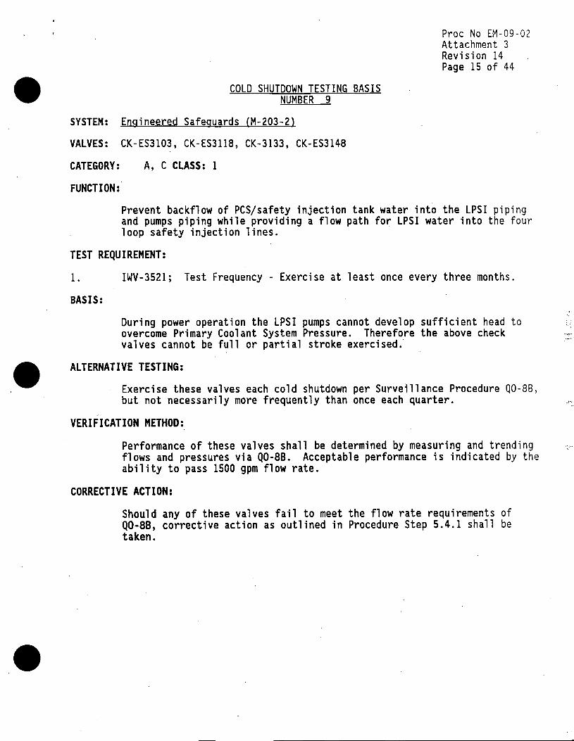
COLD SHUTDOWN TESTING BASIS NUMBER 9
Engineered Safeguards (M-203-2)
CK-ES3103, CK-ES3118, CK-3133, CK-ES3148
A, C CLASS: 1
Proc No EM-09-02 Attachment 3 Revision 14 Page 15 of 44
Prevent backflow of PCS/safety injection tank water into the LPSI p1p1ng and pumps piping while providing a flow path for LPSI water into the four loop safety injection lines.
TEST REQUIREMENT:
1. IWV-3521; Test Frequency - Exercise at least once every three months.
BASIS:
During power operation the LPSI pumps cannot develop sufficient head to overcome Primary Coolant System Pressure. Therefore the above check valves cannot be full or partial stroke exercised.·
ALTERNATIVE TESTING:
Exercise these valves each cold shutdown per Surveillance Procedure Q0-88, but not necessarily more frequently than once each quarter.
VERIFICATION METHOD:
Performance of these valves shall be determined by measuring and trending flows and pressures via Q0-88. Acceptable performance is indicated by the ability to pass 1500 gpm flow rate.
CORRECTIVE ACTION:
Should any of these valves fail to meet the flow rate requirements of Q0-88, corrective action as outlined in Procedure Step 5.4.1 shall be taken.
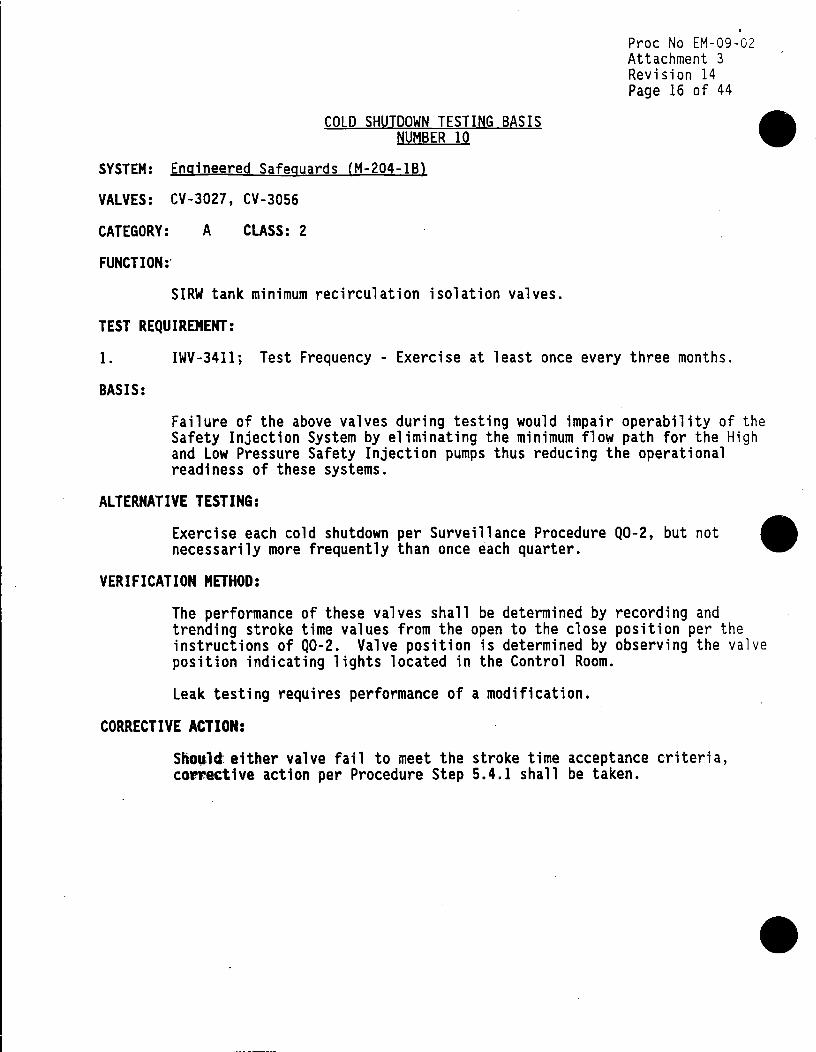
COLD SHUTDOWN TESTING BASIS NUMBER 10
Proc No EM-09-02 Attachment 3 Revision 14 Page 16 of 44
• SYSTEM: Engineered Safeguards (M-204-lBl
VALVES: CV-3027, CV-3056
CATEGORY: A CLASS: 2
FUNCTION:-
SIRW tank minimum recirculation isolation valves.
TEST REQUIREMENT:
1. IWV-3411; Test Frequency - Exercise at least once every three months.
BASIS:
Failure of the above valves during testing would impair operability of the Safety Injection System by eliminating the minimum flow path for the High and Low Pressure Safety Injection pumps thus reducing the operational readiness of these systems.
ALTERNATIVE TESTING:
Exercise each cold shutdown per Surveillance Procedure Q0-2, but not • necessarily more frequently than once each quarter.
VERIFICATION METHOD:
The performance of these valves shall be determined by recording and trending stroke time values from the open to the close position per the instructions of Q0-2. Valve position is determined by observing the valve position indicating lights located in the Control Room.
Leak testing requires performance of a modification.
CORRECTIVE ACTION:
Should: either valve fail to meet the stroke time acceptance criteria, corrective action per Procedure Step 5.4.1 shall be taken.
•

•
•
SYSTEM:
VALVES:
CATEGORY:
FUNCTION:
COLD SHUTDOWN TESTING BASIS NUMBER 11
Engineered Safeguards CM-204-1)
CK-3201, CK-3192
c CLASS: 2
Proc No EM-09-02 Attachment 3 Revision 14 Page 17 of 44
LPSI Pump discharge check valves which provide a flowpath for LPSI and Shutdown Cooling Flow and prevent backflow through the individual LPSI pumps.
TEST REQUIREMENT:
1. IWV-3521; Test Frequency - Exercise at least once every three months.
BASIS:
To verify full-stroke exercise of the above check valves requires full flow testing with the LPSI Pumps in service. This test is not possible during power operation since the necessary flow path would require the LPSI pumps to inject into the PCS. The LPSI pumps cannot develop sufficient head to overcome the PCS normal operating pressure. Therefore a full or partial stroke test cannot be performed quarterly.
ALTERNATIVE TESTING:
Full-stroke exercise each cold shutdown per Surveillance Procedure Q0-10, but not necessarily more frequently than once each quarter.
VERIFICATION METHOD:
The performance of these valves shall be determined by observing and recording shutdown cooling flow rates equal to or greater than 3000 gpm per Q0-10.
CORRECTIVE ACTION:
Should either valve fail to meet flow rate requirements, corrective action per Procedure Step 5.4.1 shall be taken •
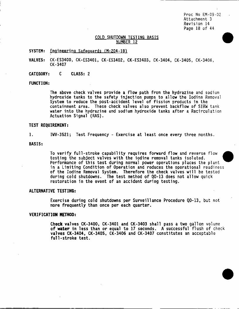
COLD SHUTDOWN TESTING BASIS NUMBER 12
Proc No EM-09-02 Attachment 3 Revision 14 Page 18 of 44
• SYSTEM: Engineering Safeguards (M-204-lBl
VALVES: CK-ES3400, CK-ES3401, CK-ES3402, CK-ES3403, CK-3404, CK-3405, CK-3406, CK-3407
CATEGORY:
FUNCTION:
c CLASS: 2
The above check valves provide a flow path from the hydrazine and sodium hydroxide tanks to the safety injection pumps to allow the Iodine Removal System to reduce the post-accident level of fission products in the containment area. These check valves also prevent backflow of SIRW tank water into the hydrazine and sodium hydroxide tanks after a Recirculation Actuation Signal (RAS).
TEST REQUIREMENT:
1. IWV-3521; Test Frequency - Exercise at least once every three months.
BASIS:
To verify full-stroke capability requires forward flow and reverse flow • testing the subject valves with the iodine removal tanks isolated. Performance of this test during normal power operations places the plant in a Limiting Condition of Operation and reduces the operational readiness of the Iodine Removal System. Therefore the check valves will be tested during cold shutdowns. The test method of Q0-13 does not allow quick restoration in the event of an accident during testing.
ALTERNATIVE TESTING:
Exercise during cold shutdowns per Surveillance Procedure Q0-13, but not more frequently than once per each quarter.
VERIFICATION METHOD:
Check valves CK-3400, CK-3401 and CK-3403 shall pass a two gallon volume of water in less than or equal to 17 seconds. A successful flush of check valves CK-3404, CK-3405, CK-3406 and CK-3407 constitutes an acceptable full-stroke test.

•
•
•
CORRECTIVE ACTION:
COLD SHUTDOWN TESTING BASIS NUMBER 12 (Continued)
Proc No EM-09-02 Attachment 3 Revision 14 Page 19 of 44
Should any valve fail to meet full-stroke flow rate for check valves requirements, corrective action per Procedure Step 5.4.1 shall be taken .

COLD SHUTDOWN TESTING BASIS NUMBER 12A
Proc No EM-09-02 Attachment 3 Revision 14 Page 20 of 44
• SYSTEM: Engineering Safeguards (M-204-lBl
VALVES: CV-0437A, CV-04378, CV-0438A, CV-04388
CATEGORY:
FUNCTION:
8 CLASS: 2
Iodine Removal System, hydrazine and sodium hydroxide tank discharge isolation valves.
TEST REQUIREMENT:
1. IWV-3411; Test Frequency - Exercise at least once every three months.
BASIS:
To full-stroke exercise the above valves requires isolating the Iodine Removal tanks. Isolating the Hydrazine and Sodium Hydroxide Tanks places the plant in a Limiting Condition of Operation and reduces the operational readiness of the Iodine Removal System. Therefore the above valves will be full-stroke exercised during cold shutdowns. Due to access limitations, the test system cannot be quickly restored in the event of a. accident during testing.
ALTERNATIVE TESTING:
Exercise during cold shutdowns per Surveillance Procedure Q0-13, but not more frequently than once each quarter.
VERIFICATION METHOD:
Control Valves CV-0437A, CV-04378, CV-0438A and CV-04388 shall stroke in less than or equal to 30 seconds. This criteria is based on system response requirements.
CORRECTIVE ACTION:
Should any valve fail to meet stroke time ,limit for control valve requirements, corrective action per Procedure Step 5.4.1 shall be taken.
•

• SYSTEM:
VALVES:
COLD SHUTDOWN TESTING BASIS NUMBER 13
Engineered Safeguards (M-204-lBl
CV-3031, CV-3057
Proc No EM-09-02 Attachment 3 Revision 14 Page 21 of 44
CATEGORY:.
FUNCTION:
A CLASS: 2
SIRW tank outlet isolation valves.
TEST REQUIREMENT:
1. IWV-3411; Test Frequency - Exercise at least once every three months.
BASIS:
Exercising CV-3031 and CV-3057 eliminates the suction source of more than one high and low pressure safety injection pump. During normal power operations this testing places the plant in an action statement per Technical Specification 3.3.2, and thus reduces the operational readiness of these systems. Therefore these valves will be exercised at cold shutdowns.
• ALTERNATIVE TESTING:
Exercise each cold shutdown per Surveillance Procedure Q0-2, but not necessarily more frequently than once each quarter. Additionally these valves are seat leakage tested each Cold Shutdown per Surveillance Procedure RT-SBA.
VERIFICATION METHOD:
The performance of these valves shall be determined by recording and trending the stroke time values from the open to the close position per the instructions of Q0-2. Valve position is determined by observing the valve position indicating lights located in the Control Room.
CORRECTIVE ACTION:
Should either valve fail to meet the stroke time acceptance criteria, corrective action per Procedure Step 5.4.1 shall be taken.

COLD SHUTDOWN TESTING BASIS NUMBER 14
SYSTEM: Engineered Safeguards (M-204-lAl
VALVES: CV-3029, CV-3030
CATEGORY: B CLASS: 2
FUNCTION:
Containment Sump Isolation Valves
TEST REQUIREMENT:
Proc No EM-09-02 Attachment 3 Revision 14 Page 22 of 44
1. IWV 3411; Test Frequency - Exercise at least once every three months.
BASIS:
one Exercising CV-3029 and 3030 eliminates the suction source of more than high and low pressure safety injection pumps. During normal Power _ Operations this testing places the plant in an action statement per Technical Specification 3.3.2, thus reducing the operational readiness of these systems. Therefore these valves will be exercised at cold shutdowns.
ALTERNATIVE TESTING:
Exercise each cold shutdown per Surveillance Procedure Q0-2, but not necessarily more frequently than once each quarter.
VERIFICATION METHOD:
The performance of these valves shall be determined by recording and trending the stroke time values from the close to the open position per the instructions of Q0-2. Valve position is determined by observing the valve position indicating lights located in the Control Room.
CORRECTIVE ACTION:
Sho«ld either valve fail to meet the stroke time acceptance criteria, corrective action per Procedure Step 5.4.1 shall be taken.
•
•

•
•
•
SYSTEM:
COLD SHUTDOWN TESTING BASIS NUMBER 15
Main Steam (M-205-1)
Proc No EM-09-02 Attachment 3 Revision /14 Page 23 of 44
VALVES: CV-0501, CV-0510
CATEGORY: B CLASS: 2
FUNCTION:.
These are the Main Steam Isolation Valves. They shut on steam generator low pressure from a MSLB to limit the PCS cooldown rate and the resultant reactivity insertion. Technical Specifications specify a maximum closing time of five seconds.
TEST REQUIREMENT:
1. IWV 3521; Test Frequency - Exercise at least once every three months.
BASIS:
These valves cannot be exercised during normal plant operation since a full-stroke exercise results in loss of steam flow to the turbine creating adverse transients and a resulting reactor trip. A partial stroke exercise is not practical during power operations since these valves fully stroke on initiation of a close signal. These valves can be exercised during hot or cold shutdown periods.
ALTERNATIVE TESTING:
Exercise each hot or cold shutdown per GOP-02, but not necessarily more frequently than once each quarter.
VERIFICATION METHOD:
The performance of these valves shall be determined by recording and trending stroke time values from the open to the close position per the instructions of GOP-02. Valve position is determined by observing the valve position indicating lights located in the Control Room.
CORRECTIVE ACTION:
Should either valve fail to meet the stroke time acceptance criteria, corrective action per Procedure Step 5.4.1 shall be taken .
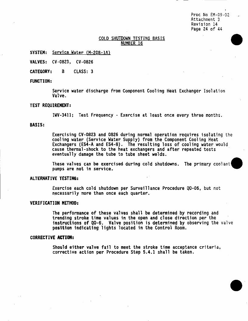
COLD SHUTDOWN TESTING BASIS NUMBER 16
Proc No EM-09-02 Attachment 3 Revision 14 Page 24 of 44
• SYSTEM: Service Water CM-208-lAl
VALVES: CV-0823, CV-0826
CATEGORY:
FUNCTION:
B CLASS: 3
Service water discharge from Component Cooling Heat Exchanger Isolation Valve.
TEST REQUIREMENT:
BASIS:
IWV-3411; Test Frequency - Exercise at least once every three months.
Exercising CV-0823 and 0826 during normal operation requires isolating the cooling water (Service Water Supply) from the Component Cooling Heat Exchangers (E54-A and E54-B). ·The resulting loss of cooling water would cause thermal-shock to the heat exchangers and after repeated tests eventually damage the tube to tube sheet welds.
These valves can be exercised during cold shutdowns. The primary coolant. pumps are not in service.
ALTERNATIVE TESTING:
Exercise each cold shutdown per Surveillance Procedure Q0-06, but not n~cessarily more than once each quarter.
VERIFICATION METHOD:
The performance of these valves shall be determined by recording and trending stroke time values in the open and close direction per the instructions of Q0-6·. Valve position is determined by observing the valve posttion indicating lights located in the Control Room.
CORRECTIVE·ACTION:
Should either valve fail to meet the stroke time acceptance criteria, corrective action per Procedure Step 5.4.1 shall be taken.
••

• SYSTEM:
COLD SHUTDOWN TESTING BASIS NUMBER 17
Component Cooling (M-209~1)
Proc No EM-09-02 Attachment 3 Revision 14 Page 25 of 44
VALVES: CV-0910, CV-0911, CV-0940
CATEGORY: A CLASS: 2
FUNCTION:
Isolation valves for comprinent cooling supply and return from containment.
TEST REQUIREMENT:
1. IWV-3411; Test Frequency - Exercise ~t least once every three months.
BASIS:
Exercising the above valves during normal operation results in loss of cooling water flow to the primary coolant pump seals. The interruption of ~ flow would cause failure of the pump seals and eventual pump bearing ., failure. This test is impractical to perform while the primary coolant pumps are in service. This testing can be performed during cold shutdowns · ·~ when the primary coolant pumps are not in service.
• ALTERNATIVE TESTING:
•
Exercise during cold shutdowns from the open to close position per Surveillance Procedure Q0-6, but not necessarily more frequently than once each quarter. Leak test each refueling outage per Surveillance Procedure R0-32.
VERIFICATION METHOD:
The performance of these valves shall be determined by recording and trending stroke time values in the close direction per the instructions of Q0-6. Valve position is determined by observing the valve position indicating lights loc,ated in the Control Room.
CORRECTIVE ACTION:
Should any valve fail to meet the stroke time acceptance criteria, corrective action per Procedure Step 5.4.1 shall be taken .

COLD SHUTDOWN TESTING BASIS NUMBER 18
Pree No EM-09-02 Attachment 3 Revision 14 Page 26 of 44
SYSTEM: Comoonent Cooling (M-209-3)
VALVES: CV-0945, CV-0946
CATEGORY:
FUNCTION:
B CLASS: 3
Component cooling water inlet to component cooling heat exchanger isolation valve.
TEST REQUIREMENT:
1. IWV-3411; Test Frequency - Exercise at least once every three months.
BASIS:
Exercising CV-0945 and CV-0946 requires isolating the component cooling water from heat exchangers E54A, E548. During normal operation the resulting loss of cooling water would cause thermal-shock to the heat exchangers and eventually damage the tube to tube sheet welds. These valves can be exercised at cold shutdowns when the heat exchangers are in service.
ALTERNATIVE TESTING:
Exercise valves to the open and close position per Surveillance Procedure Q0-6 each cold shutdown, but not necessarily more frequently than once each quarter.
VERIFICATION METHOD:
•
The performance of these valves shall be determined by recording and trending stroke time values in the close direction per the instructions of Q0-6. Valve position is determ.ined by observing the valve position indicating lights located in the Control Room.
CORRECTIVE ACJION:
Should either valve fail to meet the stroke time acceptance criteria, corrective action per Procedure Step 5.4.l shall be taken.
•

,-' '
•
•
•
SYSTEM:
VALVES:
CATEGORY:
FUNCTION:
HVAC (M-218-2}
COLD SHUTDOWN TESTING BASIS NUMBER 19
CV-1805, CV-1806, CV-1807, CV-1808
A CLASS: 2
Containment Purge Air Exhaust Isolation Valves
Proc No EM-09-02 Attachment 3 Revision 14 Page 27 of 44
TEST REQUIREMENT:
1. IWV 3411; Test Frequency - Exercise at least once every three months.
BASIS:
Exerc1s1ng the above valves during power operation is not practical since these valves are normally closed to provide containment integrity. Although the above valves do not change position to perform their containment isolation function, they may be open during refueling and be required to close to maintain containment (i.e. refueling accident). These valves can be exercised during cold shutdowns when containment integrity is not required.
ALTERNATIVE TESTING:
Exercise valves to position required to fulfill their safety function each cold shutdown per Q0-06, but not necessarily more frequently than once each quarter.
VERIFICATION METHOD:
The performance of these valves shall be determined by recording and trending stroke time values in the close direction per the instructions of Q0-6. Valve position is determined by observing the valve position indicating lights located in the Control Room.
CORRECTIVE ACTION:
Should either valve fail to meet the stroke time acceptance criteria, corrective action per Procedure Step 5.4.1 shall be taken .

COLD SHUTDOWN TESTING BASIS NUMBER 20
Proc No EM-09-02 Attachment 3 Revision 14 Page 28 of 44
SYSTEM: Service Water (M-208-lBl
VALVES: CV-0824 and CV-0847
CATEGORY: B CLASS: 2
FUNCTION:
Containment Service Water Supply/Return Isolation Valves.
TEST REQUIREMENT:
1. IWV-3411; Test Frequency - Exercise at least once every three months.
BASIS:
Exercising CV-0824 and CV-0847 during normal power operations isolates cooling water flow to the containment air coolers. Loss of cooling flow results in an immediate action statement per the Technical Specifications. These valves can be exercised during cold shutdowns when the containment air coolers are not in service.
ALTERNATIVE TESTING:
Exercise to the close position per Surveillance Procedure Q0-6 each cold shutdown, but not necessarily more frequently than once each quarter.
VERIFICATION METHOD:
•
• The performance of these valves shall be determined by recording and trending stroke time values in the close direction per the instructions of Q0-6. Valve position is determined by observing the valve position indicating lights located in the Control Room.
CORRECTIVE ACTION:
Should either valve fail to meet the stroke time acceptance criteria, corrective action per Procedure Step 5.4.1 shall be taken.
•

•
•
SYSTEM:
COLD SHUTDOWN TESTING BASIS NUMBER 21
Service Water {M-208-lAl
Proc No EM-09-02 Attachment 3 Revision 14 Page 29 of 44
VALVES: CV-0825 and CV-0878
CATEGORY:
FUNCTION:
B CLASS: 3
Safeguards Air Cooler Isolation valves for service water supply and return.
TEST REQUIREMENT:
1. IWV-3411; Test Frequency - Exercise at least once every three months.
BASIS:
VERIFICATION METHOD:
The performance of these valves shall be determined by recording and trending stroke time values in the open and close direction per the instructions of Q0-6. Valve position is determined by observing the valve position indicating lights located in the Control Room.
CORRECTIVE ACTION:
Should either valve fail to meet the stroke time acceptance criteria, corrective action per Procedure Step 5.4.l shall be taken •

COLD SHUTDOWN TESTING BASIS NUMBER 22
Proc No EM-09-02 Attachment 3 Revision 14 Page 30 of 44
• SYSTEM: Primary Coolant System (M-201-2)
VALVES: PRV-1042B and PRV-10438
CATEGORY:
FUNCTION:
B CLASS: 1
The power operated relief valves (PORV's) provide primary system overpressure protection from (1) a charging/letdown imbalance, (2) the start of a high pressure safety injection (HPSI) pump and (3) initiation of forced circulation in the PCS when the steam generator temperature is higher than the PCS temperature.
Analysis shows that when three charging pumps are operating and letdown is isolated and a spurious HPSI occurs, the PORV setpoints ensures that lOCFRSO, Appendix G pressure limits will not be exceeded. Above 430° F, the pressurizer safety valves prevent lOCFRSO, Appendix G limits from being exceeded by a charging/letdown imbalance.
The requirement that steam generator temperature be less than or equal to PCS temperature when forced circulation is initiated in the PCS ensures that an energy addition caused by heat transferred from a secondary syste. to the PCS will not occur. This requirement applies only to the initiation of forced circulation (the start of the first primary coolant pump) with one or more of the PCS cold leg temperatures less than 450° F.
Requiring the PORV's to be operable when the shutdown cooling system is not isolated (M0-3015 and M0-3016 open) from the PCS ensures that the shutdown cooling system will not be pressurized above its design limits.
TEST REQUIREMENT:
1. IWV-3411; Test Frequency - Exercise at least once every three months.
BASIS:
Opening these valves during power operatfons creates the possibility of the PCS loss of coolant ac~dent (LOCA) with a single failure of the associated PORV block valve.· Also, per Technical Specification 3.1.8.1, the PORV's are not required operable while the plant is at power operations.
•

•
•
•
ALTERNATIVE TESTING:
COLD SHUTDOWN TESTING BASIS NUMBER 22 (Continued)
Proc No EM-09-02 Attachment 3 Reviston 14 Page 31 of 44
Exercise to the open position per Surveillance Procedure Q0-6 each cold shutdown, but not necessarily more frequently than once each quarter. Cold shutdown testing shall be performed by cycling the valve using the solenoid actuator.
VERIFICATION METHOD:
The performance of these valves shall be determined by recording and trending stroke time values in the open and close direction per the instructions of Q0-6. Valve position is determined by observing the valve position indicating lights located in the Control Room. Acceptable operation shall be indicated when the valve successfully moves from the closed to the open position. No stroke time limit shall be applied (see Relief Request 15).
CORRECTIVE ACTION:
Should either valve fail to stroke, corrective action per Procedure Step 5.4.1 shall be taken, and an alternative vent path established per the requirements of Technical Specification 3.1.8.1 .

COLD SHUTDOWN TESTING BASIS NUMBER 23
Proc No EM-09-02 Attachment 3 Revision 14 Page 32 of 44
• SYSTEM: Main Feedwater System {M-207-IAl
VALVES: CV-0701, CV-0703, CV-0734 and CV-0735
CATEGORY:
FUNCTION:
B CLASS: 2
The steam generators are operated in parallel on the feedwater and on the steam sides. Each generator has a three element controller with inputs of feedwater flow, steam flow (corrected for pressure) and downcomer level. The Output of each controller when in automatic control is used to provide pneumatic signals to position the respective feedwater regulating control valve. The larger value of the two signals provides a speed control signal to the main feedwater, turbine driven pumps. When Plant power is between 5% and 25%, feedwater is automatically controlled by a single element controller monitoring steam generator downcomer level and positioning the feedwater regulating bypass valves. Four overrides are provided:
1. When contacts in the steam dump permissive switch are actuated on a main turbine trip, feedwater regulating control valves are maintained in the • position which existed prior to the switch activation. The feedwater pumps are then ramped down in speed to obtain a linear ramp flow decrease to 5% flow in 60 seconds following the trip.
2. When an abnormally high steam generator level is sensed by an independent downcomer level sensor, a signal is sent to close the associated feedwater regulating control valve and a control room alarm is annunciated.
3. During low steam generator pressure< 500 psia, the main feedwater control valves and the bypass valves are closed automatically. The operator can manually take control of the bypass valves by isolating the low steam generator pressure signal using a key switch on the control panel.
4. In order to limit Containment Pressure during the Main Steam Line Break to less than 55 psig the MFW regulating valves (CV-0701 and CV-0703) and bypass valves (CV-0734 and CV-0735) also close on containment high pressure {CHP) > 4 psig. A preliminary peak pressure calculation gives acceptable results (pressure..s_55 psig). The operator can manually take control of the bypass valves by isolating the Containment High Pressure signal.
•
•
•
COLD SHUTDOWN TESTING BASIS NUMBER 23 (Continued)
Pree No EM-09-02 Attachment 3 Revision 14 Page 33 of 44
Manual control of the feedwater flow may be assumed at anytime to circumvent malfunction of components within the system. When in manual control, the operator in the control room can:
1. Position manually each feedwater.regulating control valve,
2. Control speed of the two main feedwater pumps,
3. Open or close each feedwater stop valve and
4. Position manually each feedwater bypass regulating valve.
TEST REQUIREMENT:
BASIS:
1.
2.
3.
Exercise quarterly to the close position per the requirements of ASME Section XI, Paragraph IWV-3412{a) and {b).
Testing on a quarterly interval during power operations would result in a portion of the feedwater system being out of service for a minimum period of time in the range of 12 to 32 seconds. The actual time would be longer due to personnel reaction time and time required to perform procedure recorQings. Results would be the following:
Decrease in steam generator level possibly resulting in an Auxiliary Feedwater Actuation Signal.
Thermal shock to the steam generator caused by the loss of feedwater and subsequent reinitiation.
Variation in reactor power caused by Tqve changes as a result of steam generator level and temperature variat1ons.
Industry responses to NOMIS Report Request 90-04-081 and Network Message #3850 indicate all respondents which test their feedwater regulating and bypass valves due so at power levels less than power operations •

ALTERNATIVE TESTING:
COLD SHUTDOWN TESTING BASIS NUMBER 23 {Continued)
Proc No EM-09-02 Attachment 3 Revision 14 Page 34 of 44
Exercise to the close position per Surveillance Procedure Q0-6 each cold shutdown, but not necessarily more frequently than once each quarter. Cold shutdown testing shall be performed by cycling the valve using the normal actuation circuit.
VERIFICATION METHOD:
Full-stroke testing (open to close) shall be performed on the MFW regulating and bypass valves starting at the Palisades 90REFOUT. The current design limit stroke time value used is 30 seconds and is conservatively based on operating history experience. A special test was performed in 1984 which indicated a 20 second stroke time. Testing in
•
May 1990 as part of Facility Change package FC-906 indicates the following stroke times for the subject valves:
VALVE TIME (OPEN TO CLOSED)
CV-0701 CV-0703 CV-0734 CV-0735
16.13 SEC 15.99 SEC 6.19 SEC 7 .13 SEC
Based on this data there is a 13.87 to 23.81 second margin to the design limit of 30 seconds. These valves were added to the IST program in July 1990. ·
• The performance of these valves shall be determined by recording and trending stroke time values in the close direction per the instructions of Q0-6. Valve position is determined by observing the valve position indicating lights located in the Control Room. Acceptable operation shall be indicated when the valve successfully moves to the closed position within the specified stroke time limits.
CORRECTIVE ACTION:
Should any valve fail to stroke, corrective action per Procedure Ste' 5.4.1 shall be taken.
•

•
•
SYSTEM:
COLD SHUTDOWN TESTING BASIS NUMBER 24
Primary Coolant System (M-201-2)
Proc No EM-09-02 Attachment 3 Revision 14 Page 35 of 44
VALVES: M0-1042A and M0-1043A
CATEGORY:
FUNCTION:
A CLASS: 1
Power Operated Relief Valve (PORV) Block Valves M0-1042A and M0-1043A provide isolation capability for the PORV system. The block valves provide a flow path for feed and bleed of the pressurizer.
TEST REQUIREMENT:
1. IWV-3411; Test Frequency - Exercise at least once every three months.
BASIS:
Exercising M0-1042A or M0-1043A while the Primary Coolant System (PCS) is not depressurized will result in the respective PORV being opened by the increased inlet pressure to the PORV. This will cause depressurization of the PCS and possible damage to downstream equipment from the excessive steam flow past the PORV and Block Valves.
This test is impractical to perform during normal operations. These valves will be exercised during cold shutdowns when the PCS is depressurized.
ALTERNATIVE TESTING:
Exercise to the open position per Surveillance Procedure Q0-06 each cold shutdown, but not necessarily more frequently than once each quarter.
VERIFICATION METHOD:
The performance of these valves shall be determined by recording and trending stroke time values in the open and close direction per the instructions of Q0-6. Valve position is determined by observing the valve position indicating lights located in the Control Room. Acceptable operation shall be indicated when the valve successfully moves from the closed to the open position.

CORRECTIVE ACTION:
COLD SHUTDOWN TESTING BASIS NUMBER 24 (Continued)
Proc No EM-09-02 Attachment 3 Revision 14 Page 36 of 44
Should ~ither valve fail to stroke, corrective action per Procedure Step 5.4.1 shall be t~ken, and an alternative vent path established per the requirements of Technical Specification 3.1.8.1.
•
•
•

•
•
SYSTEM:
COLD SHUTDOWN TESTING BASIS NUMBER 25
Chemical and Volume Control (M-202-lAl
Proc No EM-09-02 Attachment 3 Revision 14 Page 37 of 44
VALVES: M0-2160
CATEGORY:
FUNCTION:
B CLASS: 2
M0-2160 is the Safety Injection and Refueling Water (SIRW) tank to charging Pump Suction isolation valve. M0-2160 opens to provide an alternate source of boration to the charging pumps suction. This flow path is gravity feed.
TEST REQUIREMENT:
1. IWV-3411; Test Frequency - Exercise at least once every three months.
BASIS:
Exercising M0-2160 open during normal plant operation would result in a significant reactivity change from the injection of concentrated boric acid into the PCS. The resulting reactor power/PCS temperature excursion could cause a reactor trip. During hot shutdown, since significant PCS boration does not occur, exercising M0-2160 can result in the.unnecessary generation of large quantities of radioactive waste, especially late in core life.
ALTERNATIVE TESTING:
Exercise during cold shutdown, but not necessarily more frequently than once each quarter, as allowed by Procedure Step 5.2.1.1. Exercising shall be performed according to procedure Q0-6, "Cold Shutdown Valve Test Procedure (includes Containment Isolation Valves)".
VERIFICATION METHOD:
Operability of M0-2160 shall be determined by observing/recording stroke time, from close to open position. Valve position is verified by observing valve position indicating lights located in the control room.

CORRECTIVE ACTION:
COLD SHUTDOWN TESTING BASIS NUMBER 25 (Continued)
Proc No EM-09-02 Attachment 3 Revision 14 Page 38 of 44
Should M0-2160 fail to meet the specified st~oke time, corrective action as outlined in procedure EM 09-02, Step 5.4.1 shall be taken and an alternate boration flow path established per Technical Specification requirements 3.2.3.
•
•
•

•
•
•
SYSTEM:
VALVES:
CATEGORY:
FUNCTION:
COLD SHUTDOWN TESTING BASIS NUMBER 26
Chemical and Volume Control (M-202-lA}
CK-CVC2141, CK-CVC2161, CK-CVC2171
c CLASS: 2
Proc No EM-09-02 Attachment 3 Revision 14 Page 39 of 44
1. To provide a flowpath from boric acid injection to suction of the charging pump.
TEST REQUIREMENT:
1. IWV-3411; Test Frequency - Exercise at least one every three months.
BASIS FOR RELIEF:
The test flowpath necessary to exercise these valves involves operating the Concentrated Boric Acid Pumps. This would result in the injection of concentrated Boric Acid in to the suction of the Charging Pumps, and subsequently into the PCS. The resulting reactor power/PCS temperature/pressure transient could cause a reactor trip. During hot shutdown, since significant PCS boration does not occur, exercising these valves can result in the unnecessary generation of large quantities of radioactive waste, especially late in core life.
ALTERNATIVE TESTING:
Exercise during cold shutdown, but not necessarily more frequently than once each quarter as allowed by Procedure Step 5.2.1.1. Exercising shall be performed according to System Operating Procedure SOP-2A, "Chemical and volume Control System Charging and Letdown; Concentrated Boric Acid".
VERIFICATION METHOD:
Verification of valve performance shall occur through the monitoring of degradation via System Operating Procedure SOP-2A, "Chemical and Volume Control System Charging and Letdown: Concentrated Boric Acidn. Exercising the valves per this procedure will verify the ability of these valves to pass 68 gpm .

CORRECTIVE ACTION:
COLD SHUTDOWN TESTING BASIS NUMBER 26 (Continued)
Proc No EM-09-02 Attachment 3 Revision 14 Page 40 of 44
Should any valve fail to meet fullstroke flow rate for stroke flow rate for check valve requirements, corrective action per Procedure Step 5.4.1 shall be taken.
•
•
•
•
•
•
SYSTEM:
COLD SHUTDOWN TESTING BASIS NUMBER 27
Safety Injection (M-203-2)
Proc No EM-09-02 Attachment 3 Revision 14 Page 41 of 44
VALVES: CK-ES3104, CK-ES3119, CK-ES3134, CK-ES3149
CATEGORY:.
FUNCTION:
AC CLASS: 1
1. To provide LPSI and HPSI flowpath to the PCS.
2. To prevent backflow of PCS, SIT, and HPSI or LPSI.
TEST REQUIREMENT:
I. IWV-3521; Test Frequency - Exercise at least once every three months to position required to fulfill function (closure test)
BASIS FOR RELIEF:
These valves perform a reverse flow stoppage function to prevent backflow of PCS, SIT, and HPSI or LPSI into the respective supply headers. Closure verification can only be performed by isolating and draining the header lines immediately upstream of these check valves. This tan only be accomplished by making a containment entry to isolate the line and drain it for leakage verification.
ALTERNATIVE TESTING:
Closure verification shall be performed at Hot Shutdown, but not · necessarily more frequently than once each quarter, as allowed by system
operating procedure S0-9, "Primary Coolant System Pressure Isolation Check Valves".
VERIFICATION METHOD:
Verification of valve leakage shall 'occur via S0-9. This procedure involves an acceptance criteria of less than .75 gpm. leakage .

CORRECTIVE ACTION:
COLD SHUTDOWN TESTING BASIS NUMBER 27 (Continued)
Proc No EM-09-02 Attachment 3 Revision 14 Page 42 of 44
Should these valves fail to meet their minimum leakage requirements, corrective action as outlined in Procedure Step 5.4.1 shall be taken .
•
•
•
•
•
SYSTEM:
COLD SHUTDOWN TESTING BASIS NUMBER 28
Service Water (M-208-lAl
Pr.oc No EM-09-02 Attachment 3 Revision 14 Page 43 of 44
VALVES: CV-0821, CV-0822
CATEGORY: B CLASS: 3
FUNCTION:
1. To provide temperature control of component cooling water by regulating service water flow out of the CCW heat exchanger.
TEST REQUIREMENT:
1. IWV-3411; Test Frequency - Exercise at least once every three months.
BASIS FOR RELIEF:
These valves are used to throttle the service water flow through the CCW Heat Exchangers. Stroke Testing these valves to the closed position could cause thermal stress to the CCW heat exchangers, leading to possible failure of the tube to tube sheet welds. This is of greater concern during winter months when service water is coldest. and throttled to a minimum.
ALTERNATIVE TESTING:
Exercise during cold shutdown, but not necessarily more frequently than once every three months as allowed by Procedure Step 5.2.1. Exercising shall be performed according to Q0-6, "Cold Shutdown Test Procedure (Includes Containment Isolation Valves). The thermal load on the CCW Heat Exchanger is much lower during cold shutdown allowing service water flow to be interrupted with no detrimental effects.
VERIFICATION METHOD:
The performance of these valves shall be determined by recording and trending the stroke times of these valves in the closed direction per the instructions of Q0-6. Valve position is determined by observing the valve position indicating lights located in the Control room.

CORRECTION ACTION:
COLD SHUTDOWN TESTING BASIS NUMBER 28 {Continued)
Proc No EM-09-02 Attachment 3 Revision 14 Page 44 of 44
Should those valves fail to meet their stroke time requirements, corrective action as outlined in Procedure Step 5.4.1 shall be taken .
•
•
•

•
•
•
RRl:
RR2:
RR3:
RR4:
RRS:
RR6:
RR7:
RRB:
RR9:
RRlO:
RRll:
RR12:
RELIEF REQUEST INDEX
Relief for Hot Leg HPSI Check Valves
Proc No EM-09-02 Attachment 4 Revision 14 Page 1 of 49
Relief for Safety Injection Check Valves for Tanks T-82A, B, C and D
Relief for Containment Spray Header Check Valves
Relief for HPSI System Check Valves
Relief for Redundant HPSI System Check Valves
Relief for Containment Sump Check Valves
Relief for SIRW Tank Check Valves
Relief for Individual HPSI Pump Check Valves
Relief for Containment Spray Pumps Check Valves
Relief for Emergency Diesel Generator Check Valves
Relief for All Containment Penetration Valves
Relief for Component Cooling Isolation Check Valves to and from Radioactive Waste Evaporators
RR13: Relief for Component Cooling Water to East and West Check Valves
RR14: Relief for Various Fast Acting Valves
RRlS: Relief for PRY Valves
RR16: Relief for Check Valves Providing HPSI Flow to Loop #1 Hot Leg
RR17:
RRlB:
RR19:
RR20:
RR21:
RR22:
RR23:
Injection Flow Path
Relief for all Applicable Check Valves Exercising Where Impractical
Relief for Auxiliary Feedwater Check Valve Closure Test
Relief for Containment Air Cooler Outlet Check Valves
Relief for Charging Line to Loop-2A Check Valve
Relief for Pressurizer Auxiliary Sptay Check Valve
Relief From Corrective Action/Plant Startup per IWV-3417b and IWV-3523
Relief From Test Frequency/Per IWV-3411 and IWV-3422 .

RELIEF REQUEST BASIS NUMBER 1
Proc No EM-09-02 Attachment 4 Revision 14 Page 2 of 49
SYSTEM: Engineering Safeguards {M-201-ll
VALVES: CK-3410
CATEGORY:. C CLASS: 1
FUNCTION:
1. Prevent PCS back leakage into the Hot Leg High Pressure Safety Injection (HPSI) lines.
2. To pass flow from the HPSI system to the Hot Leg Injection.
TEST REQUIREMENT:
1. IWV-3521; Test Frequency - Exercise at least once every three months.
BASIS FOR RELIEF:
1.
Full-stroke testing during hot plant conditions is not performed for the following reasons:
A full flow test path is not available during plant conditions greater than cold shutdown (reactor vessel head removed or equal) due to nozzle thermal shock considerations.
2. Full flow testing cannot be performed during cold shutdowns (reactor vessel head installed) due to Technical Specification HPSI pump operability limitations.
ALTERNATIVE TESTING:
Check CK-3410 shall be tested as follows:
1. CK-3410 shall be full-stroke exercised during each refueling outage according to lnservice Test Procedure R0-65, "HPSl/RHPSI Check Valve Tesi•.
System flow and pressure is recorded and trended to determine valve performance.
•
•
•

•
•
•
2.
RELIEF REQUEST BASIS NUMBER 1 (Continued)
Proc No EM-09-02 Attachment 4 Revision 14 Page 3 of 49
CK-3410 is additionally partial stroke exercised during each cold shutdown in accordance with Surveillance Procedure Q0-8B. This test partially strokes CK-3410 open using the charging pumps to pass flow to the Primary System Drain tank.
QUALIFICATION PROGRAM:
None
INSTRUMENTATION DESCRIPTION:
Th• instruments used are identified in the test document. Each instrument used to verify adherence to acceptance criteria is maintained in accordance with Palisades Administrative Procedures. Each instrument is further identified on the Equipment Data Base as "Q" or "B" in the "X" field of the Q-List Interpretation.
BASELINE DATA:
Baseline data for CK-3410 was obtained via Preoperational Test Procedure 7502-502Q. This procedure was performed in October and November of 1981 as part of Facility Change FC-502. Flow was provided by the Low Pressure Safety Injection Pumps and flows of 300 gpm with the PCS depressurized were recorded.
ACCEPTANCE CRITERIA:
Inservice Testing shall be performed during refueling outages with the Reactor Vessel Head removed. A test shall be considered acceptable when observed Hot Leg Injection flow for each path is equal to or greater than 250 gpm .
RELIEF REQUEST BASIS NUMBER 2
SYSTEM: Engineering Safeguards (Safety Injection/M-203-1)
VALVES: CK-3102, CK-ES3117, CK-ES3132, CK-ES3147
CATEGORY: c CLASS: 1
FUNCTION:
Pree No EM-09-02 Attachment 4 Revision 14 Page 4 of 49
1. Prevent PCS leakage into Safety Injection Tanks T-82A, B, C and D.
2. To pass flow from the Safety Injection Tanks to the PCS.
TEST REQUIREMENT:
1. IWV-3521; Test Frequency - Exercise at least once every three months.
BASIS FOR RELIEF:
The above check valves cannot be full or partial stroke exercised during normal power operations since exercising the valves open
•
requires discharging highly borated water from the Safety Injection • Tanks (SIT) to the Primary Coolant System (PCS). This test path is
'not possible since the PCS is normally at a pressure of approximately 2500 psig and the normal pressure of the SIT is approximately 200 psig.
ALTERNATIVE TESTING:
Safety Injection Tank Discharge check valves shall be tested as follows:
1. During each hot shutdown, these valves shall be part stroke tested according to Inservice Test Procedure Q0-8C, "ESS Check Valve Operability Test and High Pressure Safety Injection Flow Indicator Verification (Hot Shutdown).
2. Each refueling outage these check valves shall be full-stroke exercised in accordance with Surveillance Procedure R0-105, "Full Flow Test of Safety Injection Bottle check valves", or
•

•
•
3.
RELIEF REQUEST BASIS NUMBER 2 (Continued)
· Proc No EM-09-02 Attachment 4 Revision 14 Page 5 of 49
During each refueling outage, a minimum of one check valve shall be disassembled and freedom of disc motion verified per Inservice Test . Procedure RM-114, "Disassembly, Verification of Disc Motion and Reassembly of Safety Injection Tank 12" Check Valves".
QUALIFICATION PROGRAM:
None
INSTRUMENTATION DESCRIPTION:
The instruments used are identified in the test document. Each instrument used to verify adherence to acceptance criteria is maintained in accordance with Palisades Administrative Procedures. Each instrument is further identified on the Equipment Data Base as "Q" or "B" in the "X" field of the Q-List Interpretation.
BASELINE DATA:
Safety injection check valves were full-stroke tested under full system pressure and level conditions during the performance of Preoperational Test Number 12 (Preop #12). This test verified the ability of the installed system configuration to pass flow. Full flow verification maybe performed each refueling outage via procedure R0-105 or freedom of disc motion maybe verified by disassembly/inspection per RM-114 and partial stroke testing per QO-SC.
ACCEPTANCE CRITERIA:
For RM-114 the following shall occur:
1. Upon removal of the bonnet the disc will demonstrate freedom of motion through its full-stroke range.
For QO-SC the following shall occur:
1. Indication of positive flows greater than 20 gpm shall constitute an acceptable test.
For R0-105 the following shall occur:
1. Indication of positive full flow greater than 3500 gpm constitutes an acceptable test .

RELIEF REQUEST BASIS NUMBER 3
SYSTEM: Engineering Safeguards (Containment Spray/M-203-2)
VALVES: CK-ES3216, CK-ES3226
CATEGORY: c CLASS: 2
FUNCTION:
1. Prevent back flow from Containment Spray Header.
2. Provide a containment spray flow path.
TEST REQUIREMENT:
Proc No EM-09-02 Attachment 4 Revision 14 Page 6 of 49
1. IWV-3521; Test Frequency - Exercise at least once every three months.
1. IWV-3522; Exercising Procedure - Exercise to the full open position.
BASIS FOR RELIEF:
To full-stroke exercise the containment spray check valves requires
•
initiating the containment spray system and spraying down the • containment. This test is not practical during any mode of operation.
ALTERNATIVE TESTING:
These check valves are disassembled and inspected (including a manual full-stroke exercise) in accordance with Engineering Manual Procedure EM-29-02, "Preventative Maintenance Program for Check Valves" in lieu of full flow testing. This method is in compliance with Generic Letter 89-04.
In addition, these valves are partial stroke exercised every three months in accordance with Procedure Q0-10 "Containment Spray and LPSI Check Valve Test.
QUALIFICATION PROGRAM:
None
•

•
•
•
INSTRUMENTATION DESCRIPTION:
RELIEF REQUEST BASIS NUMBER 3 (Continued)
Proc No EM-09-02 Attachment 4 Revision 14 Page 7 of 49
The instruments used are identified in the test document. Each ·instrument used to verify adherence to acceptance criteria is mairitained in accordance with Palisades Administrative Procedures. Each instrument is further identified on the Equipment Data Base as "Q" or "B" in the "X" field of the Q-List Interpretation.
BASELINE DATA:
CK-3216 and CK-3226 were initially tested via Preoperational Test Procedure Number 12. Test conditions were approximately 300 gpm flow at 260 psig pressure. These readings are considered the baseline performance parameters obtained when the.plant was in new condition. Inservice testing is performed per Q0-10 under approximately the same conditions. These actions are considered sufficient to monitor for valve degradation.
·ACCEPTANCE CRITERIA:
For procedure Q0-10, indication of positive flow constitutes an acceptable part stroke test .
At each disassembly the valves will be manually exercised to verify full-stroke capability. Also the disassembled valve will be inspected to ensure the internals are structurally sound (no loose or corroded parts) .

RELIEF REQUEST BASIS NUMBER 4
SYSTEM: Engineering Safeguards CHPSI/M-203-2)
VALVES: CK-ES3104, CK-ES3119, CK--ES3134, CK-ES3149
CATEGORY: AC CLASS: 1
FUNCTION:
Proc No EM-09-02 Attachment 4 Revision 14 Page 8 of 49
1. Prevent back leakage of PCS/SI tank water into the HPSI System.
2. Provide a flow path for HPSI into the PCS.
TEST REQUIREMENT:
1. IWV-3521; Test Frequency - Exercise at least once every three months.
BASIS FOR RELIEF:
These check valves cannot be full-stroke exercised during normal power operation since the test path required to stroke open the check valves requires injecting highly borated water into the Primary Coolant System {PCS} which would result in a reactivity change power
•
reduction and possibly a pressure/temperature transient. This test • flowpath is not available during normal operations since the PCS is at a greater pressure than the HPSI/RHPSI pump discharge. In addition, the potential for an intersystem LOCA would be created if any check valve should fail, due to PCS operating pressure being greater than HPSI system design pressure. Testing at any plant condition greater than cold shutdown {reactor vessel head removed or equal} will result in thermal shock to the injection nozzles.
Full-stroke testing is not possible during cold shutdown periods due to Technical Specification 3.3 pump operability limitations below 260°F {Low Temperature Overpressurization - 10 CFR 50 Appendix G}.
ALTERNATIVE TESTING:
The HPSI check valves shall be tested as follows:
1.- During cold shutdowns each valve shall be part stroke tested per Inservice Test Procedure Q0-88, "ESS Check Valve Operability Test and High Pressure Safety Injection Flow Indicator Verification {Cold Shutdown}".
•

•
•
•
2.
RELIEF REQUEST BASIS NUMBER 4 (Continued)
Proc No EM-09-02 Attachment 4 Revision 14 Page 9 of 49
During refueling outages (rector vessel head removed or equivalent), these check valves shall be full-stroke tested per Inservice Test Procedure R0-65, "HPSI/RHPSI Check Valve Test".
QUALIFICATION PROGRAM:
None
INSTRUMENTATION DESCRIPTION:
The instruments used are identified in the test document. Each instrument used to verify adherence to acceptance criteria is maintained in accordance with Palisades Administrative Procedures. Each instrument is further identified on the Equipment Data Base as "Q" or "B" in the "X" field of the Q-List Interpretation.
BASELINE DATA:
HPSI check valves were initially tested via Preoperational Test Procedure Number 12. Observed parameters were greater than 250 gpm flow rate at pressures of approximately 1000 psig. These values were obtained when the plant was in new condition. Values are reconfirmed during refueling outages via R0-65. Between refueling outages the check valves are part stroke tested during cold shutdowns per Q0-88. These actions are sufficient to monitor for degradation in the subject valves.
ACCEPTANCE . CRITERIA:
When testing per R0-65, recorded flow rates greater than 250 gpm constitutes an acceptable full-stroke test.
When testing per Q0-88, recorded flow rates greater than 35 gpm constitute an acceptable part stroke test •

RELIEF REQUEST BASIS NUMBER 5
SYSTEM: Engineering Safeguards CHPSI/M-203-2)
VALVES: CK-ES3250, CK-ES3251, CK-ES3252, CK-ES3253
CATEGORY: c CLASS: 1
FUNCTION:
Proc No EM-09-02 Attachment 4 Revision 14 Page 10 of 49
1. Prevent back leakage of PCS/SI tank water into the Redundant HPSI System.
2. Provide a flow path for Redundant HPSI into the PCS.
TEST REQUIREMENT:
1. IWV-3521; Test Frequency - Exercise at least once every three months.
BASIS FOR RELIEF:
•
These check valves cannot be full-stroke exercised during normal power operation since the test path required to stroke open the check valves requires injecting highly borated water into the Primary • Coolant System (PCS) which would result in a reactivity change power reduction and possibly a pressure/temperature transient. This test -flow path is not available during normal operations since the PCS is -at a greater pressure than the HPSI/RHPSI pump discharge. In addition, the potential for an intersystem LOCA would be created in any check valve should fail, due to PCS operating pressure being greater than HPSI system design pressure. Testing at any plant condition greater than cold shutdown (reactor vessel head removed or equal) will result in thermal shock to the injection nozzles.
Full-stroke testing is not possible during cold shutdown periods due to Technical Specification 3.3 pump operability limitations below 2so•F (Low Temperature Overpressurization - 10 CFR 50 Appendix G).
••

•
•
•
ALTERNATIVE TESTING:
RELIEF REQUEST BASIS NUMBER 5 (Continued)
Proc No EM-09-02 Attachment 4 Revision 14 Page 11 of 49
The Redundant HPSI check.valves shall be tested as follows:
1. During cold shutdowns each valve shall be part stroke tested per Inservice Test Procedure Q0-8B, "ESS Check Valve Operability Test and High Pressure Safety Injection Flow Indicator Verification (Cold Shutdown)".
2. During refueling outages (rector vessel head removed or equivalent), these check valves shall be full-stroke tested per Inservice Test Procedure R0-65, "HPSl/RHPSI Check Valve Test".
QUALIFICATION PROGRAM:
None
INSTRUMENTATION DESCRIPTION:
The instruments used are identified in the test document. Each instrument used to.verify adherence to acceptance criteria is maintained in accordance with Palisades Administrative Procedures . Each instrument is further identified on the Equipment Data Base as "Q" or "B" in the "X" field of the Q-List Interpretation.
BASELINE DATA:
Redundant HPSI check valves were initially tested via Preoperational ~ · Test Procedure Number 12. Observed parameters were greater than 250 gpm flow rate at pressures of approximately 1000 psig. These valves were obtained when the plant was in new condition. Values are reconfirmed during refueling outages via R0-65. Between refueling outages the check valves are part stroke tested during cold shutdowns per Q0-88. These actions are sufficient to monitor for degradation in the subject valves.
ACCEPTANCE CRITERIA:
When testing per R0-65, recorded flow rates greater than 250 gpm constitutes an acceptable full-stroke test.
When testing per Q0-88, ·recorded flow rates greater than 35 gpm constitute an acceptable part stroke test •

RELIEF REQUEST BASIS NUMBER 6
SYSTEM: Engineering Safeguards (M-204)
VALVES: CK-3166, CK-3181
CATEGORY:·
FUNCTION:
c CLASS: 2
Pree No EM-09-02 Attachment 4 Revision 14 Page 12 of 49
1. Prevent back flow of water from the SIRW tank into containment sump.
2. To pass flow from the containment sump to the suction of the Engineering Safeguards pumps.
TEST REQUIREMENT:
1. IWV-3521; Test Frequency - Exercise at least once every three months.
2. IWV-3522; Exercising Procedure - Exercise to the full open position.
BASIS FOR RELIEF:
•
To full-stroke exercise the Containment sump discharge check valves • requires initiating an ESS pump and pumping containment to the SIRW tank to verify adequate flow is achieved. This testing is impractical to perform during any mode of operation due to the amount of radwaste generated and the extensive filtering of the SIRW tank necessary to reestablish water chemistry requirements.
Using any other test path to perform this full-stroke test would require removing from service one of the ESS pump suction headers. This action would not be permitted per Technical Specifications during power operations.
•
•
•
•
ALTERNATIVE TESTING:
RELIEF REQUEST BASIS NUMBER 6 (Continued)
Proc No EM-09-02 Attachment 4 Revision 14 Page 13 of 49
These check valves are disassembled and inspected (including a manual full-stroke exercise) in accordance with Enginee'ring Manual Procedure EM-28-02, "Preventative Maintenance Program For Check Valves" in lieu of full flow testing. This method is in compliance with Generic · Letter 89-04.
In addition these valves are partial stroke exercised each cold shutdown in accordance with Inservice Test Procedure Q0-02, "Recirculation Actuation System and Containment Sump Check Valves".
QUALIFICATION PROGRAM:
None
INSTRUMENTATION DESCRIPTION:
The instruments used are identified in the test document. Each instrument used to verify adherence to acceptance criteria is maintained in accordance with Palisades Administrative Procedures. Each instrument is further identified on the Equipment Data Base as "Q" or "B" in the "X" field of the Q-List Interpretation.
BASELINE DATA:
Due to system configuration these valves have not been full-stroke tested since initial installation. Initial disassembly and inspection is tentatively scheduled for the 93 Refout (CK-ES3181) and 94 Refout {CK-ES3166). This schedule is based on the priority achieved by apply EPRI NP-5479 "Application Guideline for Check Valves in Nuclear Plants".
ACCEPTANCE CRITERIA:
Indication of positive flow per Q0-2 constitutes an acceptable part stroke test per Q0-2.
At each disassembly the valves are manually exercised to verify full-stroke capability. Also the disassembled valve is inspected to ensure the internals are structurally sound (no loose or corroded parts) .

RELIEF REQUEST BASIS NUMBER 7
SYSTEM: Engineering Safeguards (M-204-lBl
VALVES: CK-ES3239, CK-ES324n
CATEGORY: AC CLASS: 2
FUNCTION:
Proc No EM-09-02 Attachment 4 Revision 14 Page 14 of 49
1. Prevent back flow of containment sump water into the SIRW tank when SIS is in the recirculation mode (containment pressurized).
2. Provide a flow path from the SIRW tank to the ESS pump suctions for safety injection flow.
TEST REQUIREMENT:
1. IWV-3521; Test Frequency - Exercise at least once every three months.
2. IWV-3522; Exercising Procedure - Exercise to the full open position.
BASIS FOR RELIEF:
•
Full-stroke exercising these valves with flow is not possible during • any plant conditions for the following reasons:
1. Flow paths do not exist which will pass the flow required to achieve a full-stroke test.
2. Valves cannot be disassembled because they cannot be isolated from the SIRW tank.
ALTERNATIVE TESTING:
Part stroke quarterly per lnservice Test Procedures Q0-10, "Containment Spray and LPSI Check Valve Test" or Q0-16, "Containment Spray Pumps". Additionally, part stroke is required for acceptable tests per Q0-16, Q0-19 and Q0-20.
QUALIFICATION PROGRAM:
None
•

•
•
•
INSTRUMENTATION DESCRIPTION:
RELIEF REQUEST BASIS NUMBER 7 (Continued)
Proc No EM-09-02 Attachment 4 Revision 14 Page 15 of 49
The instruments used are identified in the test document. Each instrument used to verify adherence to acceptance criteria is maintained in accordance with Palisades Administrative Procedures. Each instrument is further identified on the Equipment Data Base as "Q" or "B" in the "X" field of the Q-List Interpretation.
BASELINE DATA:
These valves were initially full-stroke tested at 6000 gpm and 190 psig.via Preoperational Test Procedure Number 12. Additionally, part stroke tests were performed using Preop #12 at conditions ranging from 300 gpm at 260 psig to 1500 gpm at 205 psig. These test values were obtained when the valves were in new condition. Presently, part stroke testing is conducted on a quarterly basis at 1000 gpm and 250 psig. Degradation would be shown by a change in flow rate or pressure. These test conditions provide adequate· assurance of valve disc motion and is sufficient for monitoring for valve degradation.
Part stroke at lower flow rates is achieved by Q0-16, Q0-19, and Q0-20.
ACCEPTANCE CRITERIA:
Observed test flow rates in the acceptable range for the Containment Spray pumps constitutes an acceptable test for the SIRW Tank discharge check valves .

RELIEF REQUEST BASIS NUMBER 8
SYSTEM: Engineering Safeguards CHPSI/M-204-1. IA, 18)
VALVES: CK-3168, CK-3177, CK-3183, CK-3186, CK-ES3411
CATEGORY: c CLASS: 2
FUNCTION:
Prevent back flow through the individual HPSI pump.
TEST- REQUIREMENT:
' Proc No EM-09-02 Attachment 4 Revision 14 Page 16 of 49
1. IWV-3521; Test Frequency - Exercise at least once every three months.
BASIS FOR RELIEF:
•
To full-stroke exercise these valves requires injecting SIRW tank water into the Primary Coolant System (PCS) .. This test path is not available during normal operations since the PCS is at a greater pressure than the HPSl/RHPSI pump discharge. Also the injection of the highly borated SIRW tank water into the Primary Coolant System (PCS) would result in a reactivity change power reduction and • possibly a pressure/temperature transient. Testing at any plant condition greater than Cold Shutdown (Reactor Vessel head removed or equivalent) will result in thermal shock to the injection nozzles.
Full-stroke testing is not possible during cold shutdown periods due to Technical Specifications 3.3 pump operability limitations below 260°F {Low Temperature Overpressurization - lOCFR 50 Appendix G).
ALTERNATIVE TESTING:
These valves shall be tested as follows:
1. During normal plant operations, part stroke testing shall be performed on a quarterly basis per Inservice Test Procedure Q0-19, •HPSI Pumps•.
2. Durtng refueling outages with the vessel head removed, full-stroke testing per Inservice Test Procedure R0-65, "HPSl/RHPSI Check Valve Test• shall be performed.
•

•
•
•
RELIEF REQUEST BASIS NUMBER 8 (Continued)
Proc No EM-09-02 Attachment 4 Revision 14 Page 17 of 49
QUALIFICATION PROGRAM:
None
INSTRUMENTATION DESCRIPTION:
The instruments used are identified in the test document. Each instrument used to verify adherence to acceptance criteria is maintained in accordance with Palisades Administrative Procedures. Each instrument is further identified on the Equipment Data Base as "Q" or "B" in the "X" field of the Q.:.List Interpretation.
BASELINE DATA:
These HPSI check valves were tested as follows:
1. Initial testing was performed per Preoperational Test Procedure.
2.
3.
Number 12. Test valves were 1000 psig at greater than 250 gpm ..
At each refueling outage with the vessel head removed, lnservice Test Procedure R0-65, "HPSl/RHPSI Check Valve Test" reconfirms the initial test valves. ·
Additionally, these valves are part stroke tested each quarter by Inservice Test Procedure Q0-19, "HPSI Pumps". The test values per this test are approximately 1270 psig at 175 gpm.
The testing actions are considered sufficient to monitor for valve degradation.
ACCEPTANCE CRITERIA:
1. Record of positive flow constitutes an acceptable part stroke test per Q0-19.
2. Recorded flow rates greater than 250 gpm constitute an acceptable full-stroke test per R0-65 .
i

RELIEF REQUEST BASIS NUMBER 9
SYSTEM: Engineering Safeguards (Containment Spray/M-204)
VALVES: CK-3208, CK-ES3220, CK-3230
CATEGORY: c CLASS: 2
FUNCTION:
Proc No EM-09-02 Attachment 4 Revision 14 Page 18 of 49
1. Prevent back flow of water through the Containment Spray Pumps.
2. Pass flow from the Containment Spray pumps to Containment Spray Headers.
TEST REQUIREMENT:
1. IWV-3521; Test Frequency - Exercise at least once every three months.
2. IWV-3522; Exercising Procedure - Exercise to the full open position.
BASIS FOR RELIEF:
•
To full-stroke exercise the Containment Spray Pump discharge check • valves requires initiating the Containment Spray System and spraying down the containment. This test is not practical during any mode of operation.
ALTERNATIVE TESTING:
The Containment Spray Pump discharge check valves shall be tested as follows:
Each valve shall be part stroke tested once per quarter per Inservice Test Procedures Q0-10, "Containment Spray and LPSI Check Valve Test" .
•

•
•
QUALIFICATION PROGRAM:
RELIEF REQUEST BASIS NUMBER 9 {Continued)
Proc No EM-09-02 Attachment 4 Revision 14 Page 19 of 49
These check valves are disassembled and inspected (including a manual full-stroke exercise) in accordance with Engineering Manual Procedure EM-28-02, "Preventative Maintenance Program for Check Valves" in lieu of full flow testing. This method is in compliance with Generic Letter 89-04.
In addition, these valves are partial stroke exercised every three months in acc~rdance with Procedure Q0-10 "Containment Spray and LPSI Check Valve Test.
INSTRUMENTATION DESCRIPTION:
The instruments used are identified in the test document. Each instrument used to verify adherence to acceptance criteria is maintained. in accordance with Palisades Administrative Procedures. Each instrument is further identified on the Equipment Data Base as "Q" or "B" in the "X" field of the Q-List Interpretation.
BASELINE DATA:
The Containment Spray Pump discharge check valves have been tested as follows:
I. Initial testing was completed per Preoperational Test Procedure Number 12. Test values ranged from 300 to 350 gpm at 260 psig. This testing was completed when the valves were in new condition.
2. Subsequent testing has been performed per Q0-10 and QP-16 at 300 gpm and 260 psig and 1000 gpm at 256 psig.
These testing actions are sufficient to monitor for valve degradation.
ACCEPTANCE CRITERIA:
Record of positive flow constitutes an acceptable part stroke test per Q0-10.
At each disassembly the valves are manually exercised to verify full-~troke capability. Also, the disassembled valve is inspected to ensure the internals are structurally sound (no loose or corroded parts).

RELIEF REQUEST BASIS NUMBER 10
SYSTEM: Service Water CM-208-lAl
VALVES: CV-0884, CV-0885
CATEGORY: B CLASS: 3
FUNCTION:
Pree No EM-09-02 Attachment 4 Revision 14 Page 20 of 49
Provide service water to the Emergency Diesel Generator sets on demand.
TEST REQUIREMENT:
1. IWV-3413; Power Operated Valves - Full-Stroke Time
BASIS FOR RELIEF:
•
Technical Specifications require the EOGs to be functionally tested on a monthly basis. This entails starting, loading and continued operation to verify operability of the EOG and its support systems. These valves are normally closed and fail open on a diesel start, they do not have position switches to locally or remotely exercise • the valves. Degraded valve operability would be detected through the performance of the EOG Test, therefore relief is requested from the timing requirements of IWV-3413.
ALTERNATIVE TESTING:
Perform monthly EOG operability testing in accordance with Technical Specifications Test Procedure M0-7A-l and M0-7A-2.
QUALIFICATION PROGRAM:
None
INSTRUMENTATION DESCRIPTION:
The instruments used are identified in the test document. Each instrument used to verify adherence to acceptance criteria is maintained in accordance with Palisades Administrative Procedures. Each instrument is further identified on the Equipment Data Base as "Q" or "B" in the "X" field of the Q-List Interpretation.
•
•
•
•
BASELINE DATA:
RELIEF REQUEST BASIS NUMBER 10 (Continued)
Proc No EM-09-02 Attachment 4 Revision 14 Page 21 of 49
Performance of M0-7A-1 and M0-7A-2 in lieu of quarterly stroke time testing is an acceptable alternative for the following reasons:
1. M0-7A-1 and M0-7A-2 are performed three times per quarter as opposed to a quarterly procedure which would only be performed once.
2. M0-7A-1 and M0-7A-2 monitor jacket water pressure and temperature to determine acceptable subsystem performance.
3. M0-7A-l and M0-7A-2 apply acceptable, alert and required action ranges to jacket water pressure and temperature. This action is a suitable alternative to stroke time measurements for monitoring valve degradation.
ACCEPTANCE CRITERIA:
Recorded jacket water pressures and temperatures in the acceptable range per M0-7A-1 and M0-7A-2 constitutes an acceptable test for the subject valves •
RELIEF REQUEST BASIS NUMBER 11
Proc No EM-09-02 Attachment 4 Revision 14 Page 22 of 49
SYSTEM: As Applicable
VALVES: All Containment Penetration Valves
CATEGORY:
FUNCTION:
A and AC CLASS: 1 and 2
These valves provide the primary containment barrier to minimize the consequences of an accident.
TEST REQUIREMENT:
1. IWV-3427(b); Corrective Action - For valves nominal pipe size 6 inches and larger, if a leakage rate exceeds the rate determined by the previous test by an amount that reduces the margin between measured leakage rate and the maximum permissible rate by 50% or greater, the test frequency shall be doubled.
BASIS FOR RELIEF:
Data trending for local leakage rate testing provides no meaningful information that would justify the burden of taking corrective action. With the increased frequency, operational constraints would be place upon the plant requiring extended shutdowns. Therefore, corrective action per IWV-3427(b) will not be used. This position is supported by Generic Letter 89-04.
The Appendix J, Type C testing is considered more limiting than the ASME Section XI Category A test requirements. Therefore, failure to meet the maximum allowable leakages rates as defined by the Palisades Nuclear Plant Technical Specifications is more stringent.
•
••
•

•
•
•
ALTERNATIVE TESTING:
RELIEF REQUEST BASIS NUMBER 11 (Continued)
Pree No EM-09-02 Attachment 4 Revision 14 Page 23 of 49
1. Seat leakage testing of Containment Isolation valves is performed per the requirements of 10 CFR 50 Appendix J, or as amended by the Palisades Plant Technical Specifications. Individual leakage tests are performed in accordance with the appropriate Inservice Test Procedure (R0-32).
2. Seat leakage test results of containment isolation valves are analyzed in accordance with 10 CFR 50 Appendix J, and Technical Specifications.
3. Containment isolation valve will be repaired or replaced as required when the leakage rate exceeds the maximum allowable as stated in the Palisades Nuclear Plant Technical Specifications or IWV-3427(a).
QUALIFICATION PROGRAM:
None
INSTRUMENTATION DESCRIPTION:
The instruments used are identified in the test document. Each instrument used to verify adherence to acceptance criteria is maintained in accordance with Palisades Administrative Procedtires. Each instrument is further identified oh the Equipment Data Base as "Q" or "B" in the "X" field of the Q-List Interpretation.
BASELINE DATA:
Valve leakage rates are recorded and trended. Should a leak rate approach the guideline leak rate of 13,040 cc/min, the valve is scheduled for maintenance according to the requirements of Technical Specification Surveillance Procedure R0-32, "LLRT-Local Leak Rate Test".
These actions are sufficient for monitoring valve degradation.
ACCEPTANCE CRITERIA:
The summation of all LLRT results shall be less than or equal to 56,000 cc/min (0.6L
9). T~e calculated leak rate shall be less than
the "Guideline Leak Rate" of 13,040 cc/min per penetration which is an indication of the possibility of excessive leakage .

RELIEF REQUEST BASIS NUMBER 12
SYSTEM: Comoonent Cooling CM-209-3)
VALVES: CV-0944, CV-0977B
CATEGORY: 8 CLASS: 3
FUNCTION:
Proc No EM-09-02 Attachment 4 Revision 14 Page 24 of 49
Component Cooling isolation valves to and from the Rad Waste Evaps.
TEST REQUIREMENT:
1. IWV-3411; Test Frequency - Exercise at least once every three months.
2. IWV-3413; Power Operated Valves - Full-stroke time.
BASIS FOR RELIEF:
CV-0944 and CV-09778 are normally open valves which close on SIS. There are no position switches to locally or remotely stroke the CV's. The SIS test is manpower intensive and would be difficult to
•
coordinate accurate stroke timing. Relief is requested from the • timing requirement of IWV-3414 or CV-0944 and CV-09778.
ALTERNATIVE TESTING:
CV-0944 and CV-09778 shall be stroke tested during every cold shutdown, but not more frequently than once each quarter, through the performance of the Technical Specification Surveillance Procedure Q0-1, "Safety Injection System", without stroke timing the valves.
QUALIFICATION PROGRAM:
None
INSTRUMENTATJOlt DESCRIPTION:
Th• instruments used are identified in the test document. Each instru11ent used to verify adherence to acceptance criteria is maintained in accordance with Palisades Administrative Procedures. Each instrument is further identified on the Equipment Data Base as "Q" or "B" in the "X" field of the Q-List Interpretation.
•

•
•
•
BASELINE DATA:
RELIEF REQUEST BASIS NUMBER 12 (Continued)
Proc No EM-09-02 Attachment 4 Revision 14 Page 25 of 49
Testing per Q0-1 verifies the subject valves will travel to the close position. This is considered adequate for the following reasons:
1. The valves are testing in the mode in which they would be called upon· to mitigate an accident.
2. Should one or both of these valves fail to close during an accident, an increase in flow demand of approximately 200 gpm (per FSAR Table 9.5) would be experienced. This flow increase represents approximately 3 percent of one pumps flow capacity. Should this type of failure occur; there would remain approximately 1600 gpm of excess capacity available from the Component Cooling Pumps.
Based on statements 1 and 2 testing per Q0-1 is sufficient to assure the ability of these valves to close.
ACCEPTANCE CRITERIA:
Verification of closure during the performance of Q0-1 for valves CV-0944 and CV-0977B constitutes an acceptable test •

RELIEF REQUEST BASIS NUMBER 13
SYSTEM: Component Cooling System (M-209-2)
VALVES: CK-CC401 and CK-CC402
CATEGORY: c CLASS: 3
FUNCTION:
Pree No EM-09-02 Attachment 4 Revision 14 Page 26 of 49
Component Cooling Water to east and west Engineering Safeguards check valves.
TEST REQUIREMENT:
1. IWV-3521; Test Frequency - Exercise at least once every three months.
2. IWV-3522; Exercising Procedure - Exercise to the full open position.
BASIS FOR RELIEF:
To full-stroke exercise these valves requires quantitatively
•
verifying each valve passes design accident flow. This test is not • possible during any mode of operation since no direct or indirect method of ·quantitative flow verification exists.
ALTERNATIVE TESTING:
These check valves are disassembled and inspected (including a manual full-stroke exercise) in accordance with Engineering Manual Procedure EM-28-02, "Preventative Maintenance Program for Check Valves" in lieu of full flow testing. This method is in compliance with Generic Letter 89-04.
In addition, these check valves are partial stroke exercised every three months.
QUALIFICATION PROGRAM:
No mt
INSTRUMENTATION DESCRIPTION:
The instruments used are identified. in the test document. Each instrument used to verify adherence to acceptance criteria is maintained in accordance with Palisades Administrative Procedures. Each instrument is further identified on the Equipment Data Base as "Q" or "B" in the "X" field of the Q-List Interpretation.
•

•
•
•
BASELINE DATA:
RELIEF REQUEST BASIS NUMBER 13 {Continued)
Proc No EM-09-02 Attachment 4 Revision 14 Page 27 of 49
Should there be a pipe break upstream of these check valves and subsequent failure of the same check valve, an excess flow of ·approximately 140 gallons (FSAR Table 9.5). Even under the most limiting conditions an excess capacity of approximately 1500 gpm would be available from the Component Cooling Pumps. Therefore, these valves shall be classified as Category B and part stroke tested at least once per quarter.
ACCEPTANCE CRITERIA:
An acceptable test occurs·when these valves meet the flow requirements of Inservice Test Procedures Q0-10, "Containment Spray and LPSI Check Valve Test", Q0-19, "HPSI Pumps" and Q0-20, "LPSI Pumps".
At each disassembly the valves are manually exercised to verify full-stroke capability. Also, the disassembled valve is inspected to ensure the internals are structurally sound .(no loose or corroded parts). ·

SYSTEM: As Applicable
RELIEF REQUEST BASIS NUMBER 14
Pree No EM-09-02 Attachment 4 Revision 14 Page 28 of 49
VALVES: All Fast-Acting valves w{th short stroke time less than or equal to 2 seconds.
CATEGORY: A and B CLASS: 1, 2 and 3
FUNCTION:
Various.
TEST REQUIREMENT:
1. IWV-3417(a); Corrective Action - If the stroke time increases by 50% or more from the previous test, then the test frequency shall be increased to once each month until corrective action is taken.
BASIS FOR RELIEF:
•
Fast acting valves have stroke times of such short durations that comparison of measurements with previous data for specified percentage increases is not indicative of degrading valve • performance. With measurement of stroke times to the nearest second per IWV-3413(b), a very small increase in stroke time results in a large percentage of change. Verification that these meet a specified maximum stroke time (2 seconds) of short duration, is adequate assurance of valve operability.
ALTERNATIVE TESTING:
The specified maximum limiting stroke time for all rapid acting valves is 2 seconds. Once the two second limit is exceeded, the valve s~all be declared inoperable and corrective action taken p~r IWV-3417(b).
QUALIFICATION PROGRAM:
•

•
•
•
RELIEF REQUEST BASIS NUMBER 14 (Continued)
INSTRUMENTATION DESCRIPTION:
Proc No EM-09-02 Attachment 4 Revision 14 Page 29 of 49
The instruments used are identified in the test document. Each instrument used to verify adhere·nce to acceptance criteria is maintained in accordance with Palisades Administrative Procedures. Each instrument is further identified on the Equipment Data Base as "Q" or "B" in the "X" field of the Q-List Interpretation.
BASELINE DATA:
None
ACCEPTANCE CRITERIA:
Palisades shall apply a limiting stroke time of 2 seconds for these valves. Once the two second limit is exceeded, the valve shall be declared inoperable and corrective action taken per the requirements of IWV-3417 (b) .

RELIEF REQUEST BASIS NUMBER 15
Proc No EM-09-02 Attachment 4 Revision 14 Page 30 of 49
SYSTEM: Primary Coolant System {M-201)
VALVES: PRV-1042B and PRV-10438
CATEGORY:
FUNCTION:
B CLASS: 1
The power operated relief valves (PORV's) provide primary system overpressure protection from (1) a charging/letdown imbalance, (2) the start of a high pressure safety injection (HPSI) pump and (3) initiation of forced circulation in the PCS when the steam generator temperature is higher than the PCS temperature.
Analysis shows that when three charging pumps are operating and letdown is isolated and a ~purious HPSI occurs, the PORV setpoints ensure that 10 CFR 50, Appendix G pressure limits will not be ·exceeded. Above 43o•F, the pressurizer safety valves prevent 10 CFR 50, Appendix G limits from being exceeded by a charging/letdown imbalance.
•
The requirement that steam generator temperature be less than or • equal to PCS temperature when forced circulation is initiated in the PCS ensures that an energy addition caused by heat transferred from the secondary system to the PCS will not occur. This requirement applies only to the initiation of forced circulation (the start of the first primary coolant pump) with one or more of the PCS cold leg temperatures less than 450°F.
Requiring the PORV's to be operable when the shutdown cooling system is not isolated (M0-3015 and M0-3016 open) from the PCS ensures that the shutdown cooling system will not be pressurized above its design limits.
•
•
•
•
RELIEF REQUEST BASIS NUMBER 15 (Continued)
Proc No EM-09-02 Attachment 4 Revision 14 Page 31 of 49
TEST REQUIREMENT:
IWV-1100 requires all class 1, 2 and 3 valves and their actuating and position indicating systems be tested in accordance with subsection IWV.
IWV-3413 requires a limiting value of stroke time of each valve be specified by the owner.
IWV-3417 requires an increased testing frequency and corrective action be taken if a measured stroke time exceeds 1.50 times the previous measured value for valves with full-stroke times less than or equal to 10 seconds.
BASIS FOR RELIEF:
1.
Performance of testing which includes the entire PORV actuating: circuitry poses an undo hardship for the following reasons:
This testing requires pressurization with Nitrogen between the block valves and the PORV. Radiation exposure is estimated at 300 mR per test of the PORV and actuating circuits •
Therefore, relief from the requirement of IWV-1100 is requested.
When stroked at zero differential pressure with the solenoid actuator, there are three primary forces which act on the PORV'. The following force tends to open the valves:
1. Coil force.
The following force tends to close the PORV:
1. Spring force.
Friction force opposes motion in either direction .

RELIEF REQUEST BASIS NUMBER 15 {Continued)
Pree No EM-09-02 Attachment 4 Revision 14 Page 32 of 49
Therefore, to have a healthy valve, the solenoid force must be greater than the friction force plus the spring force. This relationship is demonstrated when the valve successfully strokes from the closed to opened position. Because each of these forces is small in comparison to system pressure forces, the ability to stroke (without specification of a limiting value of stroke time) represents acceptable valve degradation and operation. Thus, relief from the requirements of IWV-3413 and IWV-3417 is requested.
ALTERNATIVE TESTING:
The PORV's shall be stroked using the solenoid actuator per Q0-06, "Cold Shutdown Test Procedure (includes Containment Isolation Valves)" at each cold shutdown but not necessarily more often than once per quarter. The ability to move from the full closed to the full open position (without the specification of a limiting value of stroke time) shall constitute an acceptable test. Each PORV and its actuating circuit shall be exercised each refueling outage per Surveillance Procedure RI-115, "Power Operated Relief Valves" Guidance of Generic Letter 89-04 position 6 shall be applied and a limiting value of two seconds shall be specified for RI-115 testing (see Relief Request 14).
QUALIFICATION PROGRAM:
MPR Associates, Incorporated analyzed the Target Rock Style SSRR valve for various conditions and concluded that total stroke open time at 330 psia/saturated water conditions will be 1.93 seconds (see MPR Study 1150, "Dynamic Analysis of Power Operated Relief Valves -Palisades Nuclear Power Plant"). This analysis is the basis to show these valves are capable of fulfilling their safety function of opening in less than 2.1 seconds per the requirements of EA-FC-809-13, Rev. 1.
INSTRUMENTATION DESCRIPTION:
The; instruments used are identified in the test document. Each instrument used to verify adherence to acceptance criteria is maintained in accordance with Palisades Administrative Procedures. Each instrument is further identified on the Equipment Data Base as "Q" or "B" in the "X" field of the Q-List Interpretation. ·
•
•
•

•
•
•
BASELINE DATA:
RELIEF REQUEST BASIS NUMBER 15 (Continued)
Proc No EM-09-02 Attachment 4 Revision 14 Page 33 of 49
Baseline data was obtained during preservice testing per Facility Change Package FC-809. This data shows the PORV's will open in approximately 1.2 seconds with 200 psia of Nitrogen test system . pressure. This value provides the baseline for monitoring valve degradation at subsequent refueling outages per RI-115.
Baseline data also obtained during preservice testing, shows each valve is capable of stroking in approximately 1.4 seconds when manually stroked with the solenoid actuator. Even though no limiting value of stroke time is specified for the PORV's when tested in this mode, this data will be trended for predictive purposes.
ACCEPTANCE CRITERIA:
Opening stroke times obtained per RI-115 which are less than or equal to two seconds shall constitute an acceptable refueling outage test.
The ability to move to the open position per Q0-06 shall constitute an acceptable cold shutdown test .

RELIEF REQUEST BASIS NUMBER 16
SYSTEM: Engineering Safeguards CRHPSI/M-203-2}
VALVES: CK-ES3408 and CK-ES3409
CATEGORY: c CLASS: 1
FUNCTION:
1. Provide HPSI to loop #1 Hot Leg injection Flow path.
2. Prevent back flow of Primary Coolant System.
TEST REQUIREMENT:
Proc No EM-09-02 Attachment 4 Revision 14 Page 34 of 49
1. IWV-3521; Test Frequency - Exercise at least once every three months.
BASIS FOR RELIEF:
To full-stroke exercise these valves requires injecting SIRW tank water into the Primary Coolant System )PCS). This test path cannot be used during normal power operations since the PCS is at a greater
•
pressure than the HPSI pump discharge. Also the injection of the • highly borated SIRW tank water into the Primary Coolant System (PCS) would result in a reactivity change power reduction and possibly a pressure/temperature transient. Testing at any plant condition greater than Cold Shutdown (rector vessel head removed or equivalent) would result in thermal shock to the injection nozzles.
Full-stroke testing is not possible during cold shutdown periods due to Technical Specifications 3.3 pump operability limitations below 2so•F (Low Temperature Overpressurization - 10 CFR 50 Appendix G).
ALTERNATIVE TESTING:
These valves shall be tested as follows:
1. During normal plant operations, partial stroke testing shall be perfonned on a quarterly basis per Inservice Testing Procedure Q0-19.
2. During refueling outages with the vessel head removed, full-stroke testing per Inservice Testing Procedure R0-65 shall be performed .
•

•
•
•
QUALIFICATION PROGRAM:
None
RELIEF REQUEST BASIS NUMBER 16 (Continued)
INSTRUMENTATION DESCRIPTION:
Proc No EM-09-02 Attachment 4 Revision 14 Page 35 of 49
The instruments used are identified in the test document. Each instrument used to verify adherence to acceptance criteria is maintained in accordance with Palisades Administrative Procedures. Each instrument is further identified on the Equipment Data Base as "Q" or "B" in the "X" field of the Q-List Interpretation ..
BASELINE DATA:
ACCEPTANCE CRITERIA:
1. Record of positive flow constitutes an acceptable part stroke testper Q0-19.
2. Recorded flow rates greater than 250 gpm constitute an acceptable full-stroke test per R0-65 .

RELIEF REQUEST BASIS NUMBER 17 .
SYSTEM: As applicable
VALVES: All applicable check valves
CATEGORY: c CLASS: 1, 2 and 3
FUNCTION:
To provide a flow path and/or prevent back flow.
TEST REQUIREMENT:
Proc No EM-09-02 Attachment 4 Revision 14 Page 36 of 49
1. IWV-3521; Test Frequency - Exercise at least once every three months.
2. IWV-3522; Exercising Procedure - Exercise to the full open position.
BASIS FOR RELIEF:
This information is provid~d for disassembly and inspection of category C check valves for which relief has been requested from ASME
•
Section XI, IWV-3521 and 3522. Specific valve relief requests have • been requested for the applicable valves as noted in the IST program document.
1. Check Valve Exercising
ASME Section XI provides an exercise procedure for Category C valves. When direct or indirect methods of exercising check valves are not available or when it is impractical to exercise a valve using system flow, the check valve will be disassembled and inspected using a sampling technique.
For check valves which cannot be verified operable by standard ASME test procedures, Palisades Nuclear Plant will verify operability by disassembly and inspection.
2. Test Frequency
Check valves will be disassembled and inspected in accordance with a sampling technique on a refueling outage basis only.
•
•
•
•
3. Sampling Technique
RELIEF REQUEST BASIS NUMBER 17 {Continued)
Proc No EM-09~02 Attachment 4 Revision 14 Page 37 of 49
The sampling technique utilized at Palisades requires that one valve .from each Group be disassembled and inspected each reactor refueling outage. More than one valve from each grouping may be disassembled and inspected each refueling outage. More than one valve from each grouping may be disassembled and inspected each refueling outage depending on outage duration.
A different valve in each Group will be disassembled and inspected at subsequent refueling outages.
All valves in each Group will be disassembled and inspected once before any one valve is disassembled and inspected twice. The scheduling will continue for subsequent inspections.
4. Check Valve Groupings
Valve Groups are defined as each valve in a group having the following identical characteristics:
a. Unit b. Manufacturer c. Size d. Model number e. Material of construction f. Service conditions (i.e., process fluid, temperature, pressure,
fl ow, etc.)
5. Disassembly/Inspection (Exercising)
Upon valve disassembly, a visual inspection of the valve internals is performed to ensure that all parts are intact and structurally sound (no loose or corroded parts).
During the visual inspection, the valve disk is manually exercised to ensure the valve is capable of full-stroking .
6. Corrective Actions
RELIEF REQUEST BASIS NUMBER 17 (Continued)
Proc No EM-09-02 Attachment 4 Revision 14 Page 38 of 49
If the disassembled valve's full-stroke capability is in question, the remaining valves in that group will be disassembled, inspected and full-stroke exercised during the same refueling outage.
If any valve fails to exhibit full-stroke capability, the valve shall be repaired or replaced in accordance with the corrective actions of IWV-3427{a).
•
•
•
•
•
•
RELIEF REQUEST BASIS NUMBER 18
SYSTEM: Auxiliary Feedwater (M-207-2)
VALVES: CK-FW703, CK-FW704, CK-FW728 and CK-FW729
CATEGORY:.
FUNCTION:
c CLASS: 2
Auxiliary Feedwater injection check valves
Proc No EM-09-02 Attachment 4 Revision 14 Page 39 of 49
1. Provide a flow path from auxiliary feedwater pumps to the steam generators.
2. Prevent back flow.
TEST REQUIREMENT:
1. IWV-3521; Test Frequency - Exercise at least once every three months.
2. IWV-3522; Exercising Procedure - Exercise to the full open position .
BASIS FOR RELi EF:
To verify closing of the above check valves requires reverse flow testing (with the other aux. feedwater pump) and quantifying the leakage past the valves. This test is impractical to perform and places constraints on normal plant operations due to the large volume of auxiliary feedwater that would be required to be drained between the check valve and upstream isolation valve prior to testing. Additionally, by isolating the upstream motor operated valve, the plant is placed in an LCO per Technical Specification 3.5.1.
ALTERNATIVE TESTING:
These check valves are verified closed during reactor refueling outages per Engineering Manual Procedure EM-28-02, "Preventative Maintenance Program for Check Valves" which is a disassembly and inspection (including a manual full-stroke exercise).
In addition leakage past the valves is monitored (not quantified) by periodically recording temperatures upstream of the check valves. Elevated temperatures would indicate leakage past the valves .

QUALIFICATION PROGRAM:
None
RELIEF REQUEST BASIS NUMBER 18 (Continued)
INSTRUMENTATION DESCRIPTION:
Proc No EM-09-02 Attachment 4 Revision 14 Page 40 of 49
The instruments used are identified in the test document. Each instrument used to verify adherence to acceptance criteria is maintained in accordance with Palisades Administrative Procedures. Each instrument is further identified on the Equipment Data Base as "Q" or "B" in the "X" field of the Q-List Interpretation.
BASELINE DATA:
None
ACCEPTANCE CRITERIA:
•
At each disassembly the auxiliary feedwater check valves are manually exercised to verify full-stroke capability. ·Also the disassembled valves are inspected to ensure the internals are structurally sound (no loose or corroded parts). •
•

•
•
•
SYSTEM:
RELIEF REQUEST BASIS NUMBER 19
Service Water CM-208-lBl
Proc No EM-09-02 Attachment 4 Revision 14 Page 41 of 49
VALVES: CK-SW407, CK-SW408, CK-SW409 and CK-SW410
CATEGORY:
FUNCTION:
c CLASS: 3
Containment air cooler outlet check valves - Provide a flow path for service water discharge from the air coolers.
TEST REQUIREMENT:
1. IWV-3521; Test Frequency - Exercise at least once every three months.
2. IWV-3522; Exercising Procedure - Exercise to the full open position.
BASIS FOR RELIEF:
To verify full-stroke exercise capability requires quantitatively verifying each of the above valves passes design accident flow rate . This test is not possible to perform since no direct or indirect method of quantitative flow verification exists.
ALTERNATIVE TESTING:
These check valves are disassembled and inspected (including a manual full-stroke exercise) in accordance with Engineering Manual Procedure EM-28-02, nPreventative Maintenance Program for Check Valvesn, in lieu of full flow testing. This method is in compliance with Generic Letter 89-04.
In addition, these valves are partial stroke exercised every three months.
QUALIFICATIOlt-PROGRAM:

RELIEF REQUEST BASIS NUMBER 19 (Continued)
INSTRUMENTATION DESCRIPTION:
Proc No EM-09-02 Attachment 4 Revision 14 Page 42 of 49
The instruments used are identified in the test document. Each instrument used to verify adherence to acceptance criteria is maintained in accordance with Palisades Administrative Procedures. Each instrument is further identified on the Equipment Data Base as "Q" or "B" in the "X" field of the Q-List Interpretation.
BASELINE DATA:
None
ACCEPTANCE CRITERIA:
At each disassembly the valves are manually exercised to verify full-stroke capability. Also, the disassembled valves are inspected to ensure the internals are structurally sound (no loose or corroded parts).
•
•
•

•
•
•
SYSTEM:
RELIEF REQUEST BASIS NUMBER 20
Chemical and Volume Control (M-202-lBl
Proc No EM-09-02 Attachment 4 Revision 14 Page 43 of 49
VALVES: CK-CVC2116
CATEGORY:
FUNCTION:
c CLASS: 2
Charging line to loop-2A check valve. Provide a flow path from the charging pump header to Primary Coolant System.
TEST REQUIREMENT:
I. IWV-3521; Test Frequency - Exercise at least once every three months.
2. IWV-3522; Exercising Procedure - Exercise to the full open position.
BASIS FOR RELIEF:
To full-flow test CK-CVC2116 requires isolating the other charging line (loop - IA) and quantifying the flow past the valve .
To accomplish this test path requires-isolating the manual valve (MV-2198) on the other charging line. This test is impractical to perform since a containment entry would be required into a high radiation area to isolate the valve. ·
This valve is full-stroke exercised during reactor refueling outages.
ALTERNATIVE TESTING:
Check valve CK-CVC2116 is disassembled and inspected (including a manual full-stroke exercise) in accordance with Engineering Manual Procedure EM-28-02, "Preventative Maintenance Program for Check Valves" in lieu of full flow testing. This method is in compliance with· Generic Letter 89-04.
QUALIFICATIOI> PROGRAM:
None
RELIEF REQUEST BASIS NUMBER 20 (Continued)
INSTRUMENTATION DESCRIPTION:
Proc No EM-09-02 Attachment 4 Revision 14 Page 44 of 49
The instruments used are identified in the test document. Each instrument used to verify adherence to acceptance criteria is maintained in accordance with Palisades Administrative Procedures. Each instrument is further identified on the Equipment Data Base as "Q" or "B" in the "X" field of the Q-List Interp~etation.
BASELINE DATA:
None
ACCEPTANCE CRITERIA:
At each disassembly the valve is manually exercised to verify . full-stroke capability. Also, the disassembled valve is inspected to ensure the internals are structurally sound {no loose or corroded parts).
•
•

•
•
•
RELIEF REQUEST BASIS NUMBER 21
Proc No EM-09-02 Attachment 4 Revision 14 Page 45 of 49
SYSTEM: Chemical and Volume Control CM-202-lBl
VALVES: CK-CVC2U8
CATEGORY:
FUNCTION:
c CLASS: 2
Pressurizer auxiliary spray check valve. Provide a flow path from the charging line to the pressurizer.
TEST REQUIREMENT:
1. IWV-3521; Test Frequency - Exercise at least once every three months.
2. IWV-3522; Exercising Procedure - Exercise to the full open position.
BASIS FOR RELIEF:
To verify full-stroke operability requires isolating the charging flow to loop IA and IB and quantifying the flow rate past the valve .
This test is impractical to perform since isolating the charging flow to the Primary Coolant System is not possible per Technical Specifications 3.2.2, and no other direct method of full-flow verification exists.
This valve is full-stroke exercised during reactor refueling outages.
ALTERNATIVE TESTING:
Check valve CK-CVC2116 is disassembled and inspected (including a manual full-stroke exercise) in accordance with Engineering Manual Proc~ at-28-02, "Preventative Maintenance Program for Check Y , .... iJtr11eu of full flow testing. This method is in compliance
.. · ·.,ttc Letter 89-04 •

I
I -
RELIEF REQUEST BASIS NUMBER 21 (Continued)
INSTRUMENTATION DESCRIPTION:
Pree No EM-09-02 Attachment 4 Revision 14 Page 46 of 49
The instruments used are identified in the test document. Each instrument used to verify adherence to acceptance criteria is maintained in accordance with Palisades Administrative Procedures. Each instrument is further identified on the Equipment Data Base as "Q" or "B" in the "X" field of the Q-List Interpretation.
BASELINE DATA:
None
ACCEPTANCE CRITERIA:
At each disassembly the valve is manually exercised to verify full-stroke capability. Also, the disassembled valve is inspected to ensure the internals are structurally sound (no loose or corroded parts).
•
•
••
•
RELIEF REQUEST BASIS NUMBER 22
Proc No EM-09-02 Attachment 4 Revision 14 Page 47 of 49
SYSTEM: All
VALVES: All
CATEGORY: As Applicable CLASS: All
As Applicable FUNCTION:
TEST REQUIREMENT:
ASHE Section XI (IWV-3417b and IWV 3523) states that when corrective action is required as a result of testing, the condition must be corrected within 24 hours or the valve shall be declared inoperative. In the event of testing during cold shutdown, condition shall be corrected prior to start-up.
BASIS FOR RELIEF:
The Palisades Nuclear Plant Technical Specification limiting conditions for operations, and ASME Section· XI, provide the controls by which valves and systems are declared inoperative. Palisades Technical Specifications also control entry into various operational conditions, which is generally more restrictive than the ASME Code, Section XI. Failure to meet Section XI testing criteria should not, therefore, preclude plant start-up with that particular component inoperative, nor should the declaration of component or system inoperability be extended to 24 hours. Plant safety .is assured by adherence to Palisades Nuclear Plant Technical Specifications.
ALTERNATIVE TESTING:
The ability to declare component or system inoperability, and conduct plant start-up, shall be governed by Palisades Nuclear Plant Technical Specifications and not by ASME Section XI, IWV-3417b and I
. ,-...

RELIEF REQUEST BASIS NUMBER 23
Proc No EM-09-02 Attachment 4 Revision 14 Page 48 of 49
SYSTEM: Al 1
VALVES: All
CATEGORY: As Applicable CLASS: All
As Applicable FUNCTION:
TEST REQUIREMENT:
IWV-3411 "Test Frequency" states, "Category A and B valves shall be exercised at least once every 3 months, except as providing by IWV-3412(a), IWV-34 and IWV-3416."
IWV-3422 "Frequency" states, "test shall be conducted at least once every 2 years."
BASIS FOR RELIEF:
Specification 4.0.2 establishes the conditions under which the
••
specified time interval for Surveillance Requirements may be • extended. Item a. permits an allowable extension of the normal . surveillance interval to facilitate surveillance scheduling and consideration of plant operating conditions that may not be suitable for conducting the surveillance; e.g., transient conditions or other ongoing surveillance or maintenance activities. Item b. limits the use of the provisions of item a. to ensure that it is not used repeatedly to extend the surveillance interval beyond that specified. The limits of Specification 4.0.2 are based on engineering judgement and the recognition that the most probable result of any particular surveillance being performed is the verification of conformance with Surveillance Requirements. These provisions are sufficient to ensure that the reliability ensured through surveillance activities is not significantly degraded beyond that obtained from the specified surveillance interval.
•
•
•
ALTERNATIVE TESTING:
RELIEF REQUEST BASIS NUMBER 23 {Continued)
Proc No EM-09-02 Attachment 4 Revision 14 Page 49 of 49
Unless otherwise specified, each surveillance requirement shall be performed within the specified time interval with:
a. A maximum allowable extension not to exceed 25% of the surveillance interval, and
b. A total maximum allowable combined interval time for any three consecutive surveillance intervals not to exceed 3.25 times the specified surveillance interval.
QUALIFICATION PROGRAM:
None
INSTRUMENTATION DESCRIPTION:
None
BASELINE DATA:
None
ACCEPTANCE CRITERIA:
None


![Plant Commissioning Start Up Procedure[1]](https://img.dokumen.tips/doc/110x75/553e03554a79597c268b480e/plant-commissioning-start-up-procedure1.jpg)