Embed Size (px)
Citation preview

Return Channel for the BrazilianDigital Television
System-TerrestrialLuís Geraldo P. Meloni1
1Department of CommunicationsSchool of Electrical and Computing Engineering
State University of CampinasP.O.Box 6101, Zip 13083-852 - Campinas - SP - BRAZIL
AbstractRecently, it has been proposed the use of WiMAX
for the return channel in digital television systems usinga new frequency profile bellow 1 GHz, which has beencalled WiMAX-700. The profile operates from 400 MHz to960 MHz as primary band, which includes the UHF band,and optionally from 54 MHz to 400 MHz as secondaryband. This work presents some aspects of the WiMAX-700 technology and some simulation results of models de-signed to determine the system capacity concerning thenumber of actives subscriber stations, according to spe-cific proposed scenarios, traffic sources profiles, specificspropagation, and coverage conditions. The results pre-sented in this work provide elements to determine the suit-ability of WiMAX-700 technology as the return channelfor the interactive digital television applications.
Keywords: WiMAX-700, IEEE 802.16, 700MHzprofile, Digital Television Systems, Return Channel, NS-2
1. INTRODUCTIONBrazil has recently defined its Digital TV System
based on the Japanese ISDB-T. The Brazilian system(SBTVD-T) uses the same modulation technique of theISDB-T system, also known as BST-OFDM - Band Seg-mented Transmission - Orthogonal Frequency DivisionMultiplexing, which consists of a series of frequencyblocs called OFDM segments that provide DTV transmis-sion for fixed and mobile receivers simultaneously. TheOFDM segments use different transmission parametersallowing a hierarchical transmission.
Among the Brazilian innovations, there is a new pro-posal of middleware that is based on the NCL language,that is a declarative language for hypermedia documentsauthoring and object synchronizing. Another importantinnovation regards a new WiMAX profile that cover theUHF and VHF television bands which is the main pur-pose of this paper.
The SBTVD-T standards are based on ARIB stan-dards. Concerning the Return Channel (RC), amongthe technologies currently previewed in ARIB are dial-up modems, ISDN for wired lines and PDC - Per-sonal Digital Cellular and PHS - Personal Handy-PhoneSystem for wireless. PDC is a standard developedand used exclusively in Japan. The SBTVD-T hascomplemented the above return channel technologiesby including WiMAX/WiMAX-700, GSM/GPRS, andCDMA2000/1xRTT.
The main motivation to include wireless standards asreturn channel in the SBTVD-T is the increasing observedrate of mobile phone users in Brazil, having surpassed thenumber of fixed lines by more than two folds. It is ex-pected that the same rising rate will be observed in wire-less Internet access in this decade.
The WiMAX-700 is a new WiMAX profile that cov-ers 400 MHz to 960 MHz band, including all UHF TVchannels and also optionally including the VHF band, byincluding a secondary band from 54 MHz to 400 MHz.The WiMAX-700 presents several advantages over cur-rent profiles: better indoor penetration, higher propaga-tion reach of up to 65 km, and lower cost due to the factthat the system uses components and modules of the en-tertainment electronics that present lower cost over the

Luís G. P. Meloni Return Channel for the Brazilian DigitalTelevision System-Terrestrial
telecommunications and information technologies. Thehigher propagation reaches are important in cities withlow density population allowing the use of only one basestation in the return channel network.
This paper is structured as follow: section II dealswith WiMAX-700 as return channel for the SBTVD-T,section III presents WiMAX-700 channeling techniques,section IV presents some results of a simulation environ-ment including several traffics estimates; and finally sec-tion V concludes the paper.
2. WIMAX AS RC FOR TEH SBTVD-TThe initial idea of interactivity in Digital Television is
the possibility of data communications between receiverstations with applications and services eventually avail-able in the broadcaster’s signal. Data communicationsto the majority amount of set-top boxes is implementedby means of data carrousel of the broadcaster transmitterstation. The inverse link data communications normallyuses a subsystem called return channel, which allows ingeneral in the DTV systems only half duplex communi-cations and allows low bit rates transmissions, such as theReturn Channel Terrestrial from DVB-T. In the SBTVD-T the return channel is full duplex and the middlewareexplores this functionality.
One of the available technologies for interactivitychannel is WiMAX which offer great communication ca-pability for the DTV return channel subsystem. The Fig-ure 1 shows the return channel scheme supported by theSBTVD-T.
The figure shows the three subsystems of the DTV.The broadcast subsystem generates the transport streamfor broadcasting transmission. The transport stream mul-tiplexes video, audio, and data. The video coding of theSBTVD-T uses the H.264, level 4.0, offering a high reso-lution of 1080i. Audio coding uses the HE-AAC standard.The receiver implements the inverse operation for dis-posing data for users. Finally, the return channel allowsthe communications between uses and interactive applica-tions at the broadcaster or at any server connected to theInternet, outside the broadcast facilities. In this schemethe access to Internet is independent of the return channeltechnology.
WiMAX has the advantage to full duplex transmis-sion, offering high bitrate to users, besides the compati-bility with packets networks also offering access to Inter-net.
2.1. WIMAX-700 APPLICATION IN THE SBTVD-TThe use of WiMAX at the 700 MHz profile offers sev-
eral advantages [1] [2]: better indoor penetration whencompared to other profiles; better signal reach of up to
65 km, offering return channel to low density populationareas with only one base station, and also due to the factof using entertainment components, the final system costsare lower when compared to the communications and in-formation technologies.
These advantages justify the interest of defining anew frequency profile of WiMAX-700 which includes theUHF band and optionally the VHF band. The Figure 2illustrates wireless transmissions of the proposed returnchannel for the SBTVD-T.
The WiMAX-700 radiofrequency solution uses awireless modem for the previewed frequency band. Themodem communicates with the base station offering In-ternet access. The modem disposes the return channel tothe set-top box by means of the USB or Ethernet inter-faces. The modem may also include a firewall or routerfunctionalities for Internet access to other devices such asPCs, PDAs or others. The WiMAX modem can also beintegrated inside the STB.
Several important aspects concerning the Figure 2scheme are relevant. The return channel is not neces-sarily linked to the broadcast station, i.e., the broadcaststation and the return channel provider may be physicallyseparated. A common scenario in a big city would be forinstance the use of a single broadcast antenna in an appro-priated high location and several base stations spread overthe city in a distribution similar to the cells as in mobileservices. In his manner, the system deployment dependson the existence of a entity denominated Return Chan-nel Provider. This entity may be private or public, and ithas fundamental importance, it is responsible for planningservices, system deployment, users’ registry, and base sta-tion operations, among other responsibilities.
Some WiMAX-700 requirements are presented in Ta-ble 1 for the SBTVD-T.
2.2. NETWORK ARCHITECTURE
The proposed return channel provides a wireless com-munications to a nearby base station. This scheme allowsthe coexistence of DTV broadcast networks with a wire-less telecommunications networks. The networks archi-tecture is shown in Figure 3. The base station indicatedby letter A is responsible by TV signal broadcast cover-ing the service area. The return channel is implementedby means of a transceiver (sender and receiver) at the userset-top box, which besides the digital TV reception; it hasa low-power transceiver that allows data communicationsto a nearby return node representing a base station. Let-ter B in Figure 3 represents users and letter C the returnnodes. This scheme is similar to mobile telephony wherethe coverage cells are defined by the radio bases. It is alsopossible to use the same conventional antenna for VHFand UHF for WiMAX-700 targeting low cost receivers.
In this scheme the return channel nodes have equip-
84

Luís G. P. Meloni Return Channel for the Brazilian DigitalTelevision System-Terrestrial
Figure 1. Full-duplex Return Channel with Internet Access.
Figure 2. Return Channel Architecture with WiMAX-700.
ments for wideband Internet access, representing by letterD in Figure 3. The responsability of these connectionsare from the return channel provider, and it can be pro-vided by different forms. In some places, depending onthe availability, optical linking, Ethernet or other can beused; another alternative of lower cost is the use of point-to-point wireless links.
The STB may also use different return channel modal-ity, the SBTVD-T middleware manages which returnchannel will be in use.
The IEEE802.16 standard defines a specification forair interface for wireless Metropolitan Area Networks(MAN). This wireless MAN may offer wideband Inter-net access, an alternative for other access modalities suchas cable or fiber optics, offering a less expensive solution.It is an access solution for the last mile that fulfills the
requirements of the return channel of the SBTVD-T. TheWiMAX-700 is included in the SBTVD-T specifications,which details the necessary enhancements for operatingwitch the DTV system in the new frequency profile.
The use of IEEE802.16 as return channel for DTV of-fers several advantages. Upgrades and enhancements ofthe WiMAX which occurs along the standard evolutionmay be promptly incorporated in the return channel, suchas the recent IEEE802.16e revision that allows mobility.With this revision is possible to use WiMAX in mobileDTV terminals, considering naturally the respective up-grade in the SBTVD-T.
85

Luís G. P. Meloni Return Channel for the Brazilian DigitalTelevision System-Terrestrial
Table 1. Some Characteristics of IEEE802.16 Standard.
Functional Requirements DescriptionPhysical Layer (PHY) - According to the IEEE802.16 Standard in [3] and [4];
- Coverage radius may reach approximately 65 km, appropriated to rural areas;- NLOS - Non Line of Sight;- Operation in the 400 MHz to 960 MHz, and optionally in the VHF band.
Medium Access Layer (MAC) - According to the IEEE802.16 Standard in [3] and [4];- Compatible with system architectures base on packets, such as TCP-IP, IP proto-cols, Ethernet/IEEE 802.3 , etc.- Connection oriented services;- PMP - Point to Multipoint;- Manageable QoS.
Interface with Other Modules - USB preferably;- Ethernet IEEE 802.3;- Compatibility with upper layer network and transport protocols.
Mobility - Allows receiver mobility - IEEE802.16e-2005.Identification - Each modem has a single identifier (ID).
3. WIMAX-700 CHANNELINGSeveral improvements have been introduced in the
WiMAX-700 mainly concerning the synchronization andequalization techniques, [5], [6], and [7]. This section re-view the scheme proposed in the SBTVD-T concerningspectrum channeling.
WiMAX-700 allows wireless communications in thefrequency of 400 MHz to 960 MHz, which includes theUHF (Ultra High Frequency) band, and optionally in-cludes the VHF (Very High Frequency) band.
The channeling method allows simultaneously op-eration of the digital transmission systems by meansof OFDM/OFDMA techniques or other techniques insuch way to allow coherent operation with the ana-logue or digital television systems. The method allowsthe reutilization of frequencies for transmission usingOFDM/OFDMA modulation in free channels at the de-fined frequency profile, operating harmonically with othersystems, with emphasis to the television broadcasting andmobile telephone services.
The television systems around the world use the fol-lowing bandwidths: 6 MHz, 7 MHz or 8 MHz. With pur-pose to harmonize WiMAX with the several standards,the following bandwidths and the respective masks havebeen defined to the WiMAX-700:
• 1.5 MHz, 2 MHz, 3 MHz, 6 MHz or 12 MHz - fortelevision system with 6 MHz channeling,
• 1.75 MHz, 3.5 MHz, 7 MHz or 14 MHz - for televi-sion system with 7 MHz channeling,
• 2 MHz, 4 MHz, 8 MHz or 16 MHz- for televisionsystem with 8 MHz channeling.
In WiMAX-700 the following channeling is defined bythe initial frequency:
fi = Sf + nBT + kBW ; (1)
where: Sf is the starting frequency of the TV systemsin MHz, according to different global systems, n e k areintegers,
BT ∈ {6, 7, 8} [MHz]
represents television channel bandwidth; and
BW ∈ {1.5, 1.75, 2, 3, 3.5, 4, 6, 7, 8, 12, 14, 16} [MHz]
defines the bandwidths of WiMAX channels. For in-stance, for operation of WiMAX-700 in Brazil, the fol-lowing values are used:
Sf ∈ {54, 76, 174, 470} [MHz], and
BW ∈ {1.5, 2, 3, 6, 12} [MHz].
Generally the WiMAX systems employ frequency reusefactor of 3, or even 1, in which case is implemented an in-ternal frequency reuse, by means of a sub-channeling orfrequency hopping. Such reuse factors of 3 or 1 may bedifficultly considered in the 600 MHz or 700 MHz bands.In this case, the signal propagation has different charac-teristics, and the reuse patterns may be similar to those ofmobile phones operating at frequencies bellow 1 GHz.
Several reuse patterns are possible; some of them areillustrated in Figure 4 and Figure 5. Figure 4 shows reusepattern of 4x1 and 4x3, for only one sector cells or threesectors of 120 ◦C. In these cases, 4 and 12 frequencies areused respectively. The base station antennas are placed inthe center of each hexagon. In the first case, using 1.5
86

Luís G. P. Meloni Return Channel for the Brazilian DigitalTelevision System-Terrestrial
Figure 3. WiMAX-700 Architecture as DTV Return Channel.
MHz WiMAX it is necessary one 6 MHz TV channel,and in the second case, using 2 MHz WiMAX, it is nec-essary to use four 6 MHz TV channels. Figure 5 showsreuse pattern of 7x1 and 7x3, for only one sector cellsor three sectors of 120 ◦C. In these cases 7 and 21 fre-quencies are used respectively. In the first case, using 1.5MHz WiMAX it is necessary two 6 MHz TV channel, andin the second case, using 2 MHz WiMAX, it is necessaryto use seven 6 MHz TV channels. Naturally, other reusefrequency patterns are possible within WiMAX-700 sys-tems.
4. WIMAX-700 CAPACITY SIMULA-TION
For purposes of performance analysis, several simu-lation models of the IEEE 802.16 wireless network havebeen implemented to simulate air interface traffic of thereturn channel of DTV [2]. The model reproduces themechanism of IP packets transmission between a base sta-tion and the subscriber stations (SS) of a sector controlledby the base station (BS).
The simulator uses the NS-2 environment [8], whichhas a set of elements to simulate data transmission net-works, for example IP protocol, wire and wireless trans-missions systems, and MAC protocols (IEEE 802.11 andTDMA). A new element was developed to simulate theIEEE 802.16 protocol which was employed over sev-eral rounds of simulations to analyze the IEEE 802.16network capability performance for DTV return chan-nel. The NS-2 is a discrete events simulator specializedin computers networks simulation. The NS-2 is opensource a software and an object-oriented simulator, writ-ten in C++, which allows code reutilization and modular-
ity. These characteristics make possible a fast model de-velopment of the MAC layer of the IEEE 802.16 protocol[9], [10], and [11].
4.1. SCENARIOS OF SIMULATION
The simulation analysis uses only a basic scenariowhich reproduces operation in a sector controlled by onebase station. The scenario was simulated several times,using distinct parameters of propagation, distinct param-eters of SS distributions, different types of SS traffic aswell as the number of SS.
In general, two points of view are very important formobile systems: signal propagation and channel trafficcapacity. The signal propagation determines the majorradius of cells (or sector), so that the received power in-tensity is appropriate for a good system performance. Thetraffic capacity determines the major number of SS sup-ported by a cell (or sector). In general, in the urban areas,the cells radius is limited by the traffic capacity and in therural areas by the propagation features. The main purposeof the simulation model is to allow an analysis concerningthe traffic capacity point of view.
It is specified the transmission mode of each node rep-resenting a base station in the model. The transmissionmode determines the modulation scheme (BPSK, QPSK,16-QAM and 64-QAM - for IEEE802.16d) and the er-ror correction code scheme, both defined by the standard.These parameters determine the transmission rate, as wellas the error rate for a specific signal to noise ratio level.In a real network, the transmission modes are determinedfrom the power level, interference and error rate measure-ments of the received signal. These parameters are entriesfor the simulation model.
In order to specify the sectors traffic capacity, two sce-narios were used for wireless propagation and SSs distri-butions. Without loss of generality, both models have acircular sector of one km radius. From the traffic pointof view, the cell radius and the sectors geometries are im-portant only to determine the number of SSs which uti-lize each transmission mode. For example, a circular sec-tor (360 degrees) that covers a certain area with a certainSS density has the same number of SS of such a sectorof 120 degrees covering an area three times bigger. Fromthe simulation view point, the capacity in both cases is thesame. The factor that introduces any cell capacity varia-tion is the signal propagation. The number of SS distribu-tion operating in each operation mode is slightly differentin function of signal attenuation due to path losses. TheCOST 231 [12] propagation model was used to analyzethe cells capacity and two approaches were defined de-pending on loss factors. The first approach, called P26,has considered a loss factor of 2.6, which is a typical fac-tor for urban and suburban areas. The second, called P35,has considered a 3.5 loss factor, which represents an area
87

Luís G. P. Meloni Return Channel for the Brazilian DigitalTelevision System-Terrestrial
Figure 4. Reuse Frequency Patterns.
Figure 6. SS Distribution for P26 Scenario.
with bad propagation characteristics, such as a density ur-banized areas with irregular topography.
In order to define the number of SS operating in eachtransmission mode, it was considered an homogeneousdistribution of SS in a circular area.
Six circulars sectors were created in both scenarioscalculated from the reach of the transmission signal ineach mode. A percentage SS distribution was defined foreach sector. This percentage is equal the rate between thesector area and the total area of the cell. The total num-ber of SS in the cell is defined for each simulated sce-nario. The simulation model distributes the SS in eachsector and associates them to the corresponding transmis-sion mode (Table 2).
The transmission mode in the direct and reverse path
is different for a same sector. The difference between ap-proaches P26 (Figure 6) and P35 (Figure 7) is that theapproach P35 has a higher SS concentration in the highertransmission rates. In conditions of bad transmissions,a higher transmission power is needed (or in an equiva-lent way, a reduction of the cell radius). An effect alsorelated to higher signal attenuation in P35 scenario, isthe small sectors area corresponding to a particular mod-ulation scheme at the cell border, as compared to P26scenario which has a smaller attenuation factor. Con-sequently, the approach with worst propagation factor isparadoxally the scenario more favorable regarding trafficflow.
Four traffic profiles were specified in simulations:WEB, low rate bidirectional stream, e-mail and low rateclient/server session communications. These also definefive different profiles distributions which were consideredfor the rounds of simulation (Table 3). The table presentsthe distributions of the active SS that generate the respec-tive traffic according to the percentage shown in the table.
Table 2. Percent Distribution of SS in the Sectors.Mode SS
UL DL P26 P35QPSK 1/2 QPSK 3/4 30 23QPSK 3/4 16-QAM 1/2 41 37
16-QAM 1/2 16-QAM 3/4 9 916-QAM 3/4 64-QAM 2/3 12 1564-QAM 2/3 64-QAM 3/4 1 264-QAM 3/4 64-QAM 3/4 7 14
88

Luís G. P. Meloni Return Channel for the Brazilian DigitalTelevision System-Terrestrial
Figure 5. Reuse Frequency Patterns.
Figure 7. SS Distribution for P35 Scenario.
Next, the characteristics of each traffic profile are pre-sented:
1. Web: This profile utilizes the connections sourcemodel using default parameters of the Packmimemodel (PackMimeHTTP - Bell Labs) [13] with rateof 1 page access per 2 minutes per station.
2. Low Rate client/server Session: to simulate this pro-file a new agent was created in the NS-2 with thefollowing parameters:
• Request packets length: exponential distribu-tion with mean of 512 bytes.
• Response packets length: exponential distribu-tion with mean of 50 Kbytes.
• Connections rate done by user: 10 per hour.
• Request packets number per connection: expo-nential distribution with mean of 8.
• Time delay to send response packets after re-ception of request packets: 0.
• Time delay to send the next request packets af-ter reception of response packets: negative ex-ponential distribution with mean of 20 seconds.
3. E-mail: the profile utilizes the On-Off source model(Application/Traffic/Exponential)with the followingparameters:
Receiving E-mails:
• Transmission rate in the active state: 240kbits/s
• Messages length: 15 kbytes.
• Activity period mean time: 4 seconds.
• Inactivity period mean time: 1200 seconds.
Sending E-mails:
• Transmission rate in the active state: 16 kbits/s.
• Messages length: 200 bytes.
• Activity interval mean time: 0.1 second.
• Inactivity interval mean time: 600 seconds.
4. Low Rate Bidirectional Stream: This profile uses themodel of simple variable rate (Application/Telnet),with the parameters:
• Transmission rate: 1 message each 10 seconds.
• Message Length: 100 Bytes.
89
Luís G. P. Meloni Return Channel for the Brazilian DigitalTelevision System-Terrestrial
The simulation used the NS-2 routing protocol DSDV(Destination Sequence Distance Vector) [8]. This proto-col allows systems simulation in the radio environment.In the model, the IP layer of each SS has an agent whosends periodically packets of routing to the neighbors SS.When the agents receive the packets, they obtain the nec-essary information to construct the routing table, whichwill be used to redirect the traffic. All the rounds of sim-ulation have both the application traffic and that traffic inthe IP layer. It is worth to remark that the DSDV protocolhas been used for the simulation purposes, but may not bepresent in WiMAX environment. Several rounds of simu-lation were executed for each arrangement of propagationscenario and for each traffic scenario, as varying the num-ber of SS in the sector. The number of SS was assumedto vary between 500 and 1000, with increments of 50 SSfor each simulation step.
Table 3. Percent Distribution of SS in the Sectors.Profile WEB Session E-mail Bidirectional
StreamCI-Low 0% 0% 0% 100%
CI-1 0% 0% 90% 10%CI-2 0% 50% 45% 5%
WEB-1 25% 37% 34% 4%WEB-2 50% 25% 22% 3%
4.2. CONFIGURATION MODEL
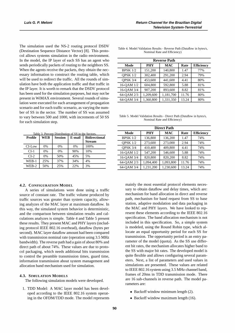
A series of simulations were done using a trafficsource of constant rate. The traffic volume produced bytraffic sources was greater than system capacity, allow-ing analyzes of the MAC layer at maximum dataflow. Inthis way, the simulated system behavior is deterministic,and the comparison between simulation results and cal-culations analyzes is simple. Table 4 and Table 5 presentthese results. They present MAC and PHY layers (includ-ing protocol IEEE 802.16 overhead), dataflow (bytes persecond). MAC layer dataflow amount had been comparedwith transmission nominal rate (operation using 3.5 MHzbandwidth). The reverse path had a gain of about 80% anddirect path of about 74%. These values are due to proto-col packaging, which needs additional bits transmissionto control the preamble transmission times, guard time,information transmission about system management andallocation band mechanism used for simulation.
4.3. SIMULATION MODELS
The following simulation models were developed.
1. TDD Model: A MAC layer model has been devel-oped according to the IEEE 802.16 system operat-ing in the OFDM/TDD mode. The model represents
Table 4. Model Validation Results - Reverse Path (Dataflow in bytes/s,Nominal Rate and Efficiency)
Reverse PathMode PHY MAC Rate Efficiency
BPSK 1/2 151,200 140,800 1.47 77%QPSK 1/2 302,400 291,200 2.94 79%QPSK 3/4 453,600 441,600 4.41 80%
16-QAM 1/2 604,800 592,800 5.88 81%16-QAM 3/4 907,200 893,600 8.82 81%64-QAM 2/3 1,209,600 1,181,700 11.76 80%64-QAM 3/4 1,360,800 1,331,350 13.24 80%
Table 5. Model Validation Results - Direct Path (Dataflow in bytes/s,Nominal Rate and Efficiency)
Direct PathMode PHY MAC Rate Efficiency
BPSK 1/2 136,800 136,200 1.47 74%QPSK 1/2 273,600 273,000 2.94 74%QPSK 3/4 410,400 409,800 4.41 74%
16-QAM 1/2 547,200 546,600 5.88 74%16-QAM 3/4 820,800 820,200 8.82 74%64-QAM 2/3 1,094,400 1,093,800 11.76 74%64-QAM 3/4 1,231,200 1,230,600 13.24 74%
mainly the most essential protocol elements neces-sary to obtain dataflow and delay times, which are:mechanism for band allocation in direct and reversepath, mechanism for band request from SS to basestation, adaptive modulation and data packaging inthe MAC and PHY layers. We have looked to rep-resent these elements according to the IEEE 802.16specification. The band allocation mechanism is notincluded in this specification. So, a simple systemis modeled, using the Round Robin type, which al-locate an equal opportunity period for each SS fortransmission. The opportunity period is an entry pa-rameter of the model (quota). As the SS use differ-ent bit rates, the mechanism allocates higher band tothe SS with major bit rates. The developed model isquite flexible and allows configuring several param-eters. Next, a list of parameters and used values insimulations are presented. These values are relatedto IEEE 802.16 system using 3.5 MHz channel band,frames of 20ms in TDD transmission mode. Thereare 16 sub-channels in reverse path. The model pa-rameters are:
• Backoff window minimum length (2).
• Backoff window maximum length (16).
90

Luís G. P. Meloni Return Channel for the Brazilian DigitalTelevision System-Terrestrial
• MAC layer packets overhead (12 octets).
• Frame length (20 ms).
• Symbol duration (68 µs).
• Frame guard time (300 µs).
• Number of direct path sub-channels (1).
• Number of reverse path sub-channels (16).
• Number of bytes per symbol per transmissionmode (12, 24, 36, 48, 72, 96, 108).
• Multiplexing type (TDD)
• Quota per station used in band allocation al-gorithm (direct path: 4 slots, reverse path: 64slots).
• Sub-frame minimum duration (number ofslots) of reverse path in TDD mode (8).
• Burst minimum length (number of slots) toeach transmission mode (direct path: 1 to allmodules; reverse path: 8, 4, 4, 2, 2, 1, 1).
• Number of channels for band allocation request(48).
• Number of codes for band allocation request(8).
• Number of opportunities for band allocation re-quest per frame (2).
• Ranging phase duration (number of symbols)in reverse path (3).
• First burst (preamble) duration (number ofslots) in direct path (5).
• Periodicity of statistical logging (1 second).
• Trace level (1).
The level trace 1 generates a registry file to storeand collect statistical. These include packets totaldataflow (number of octets) and average time delayin direct and reverse paths. Dataflow is measuredin enlace layer (MAC entry), which regards only thetraffic in upper layers, and in Physical layer (MACexit), which considers the additional bytes in pack-aging of the MAC layer. The packets delay time con-siders the waiting time of transmission and its owntransmission time.
2. FDM Model: The FDM model was developed, butnot used in the Digital TV return channel study, dueto the fact that it presents disadvantages in flexibility,once the available band for direct and reverse paths isconstant, in contrast to TDD mode where band shareis dynamic.
4.4. RESULTS ANALYZES
The tables 6, 7, and 8 present results for the sametraffic and propagation scenarios for different number ofSS. They present dataflow in the physical layer, includingIEEE 802.16 protocol overhead, and dataflow in the en-lace layer (IP dataflow). All rounds simulate 10 minutesof network operation. To analyze results, only the final 2minutes have been considered to ensure that the data out-put were in a statistical stable region. The obtained resultscorrespond to confidence interval lower then 1% averagevalues to a confidence level of 95%. In the result analyzesall rounds of simulation whose packets time delay werestationary around its mean value were considered. This isthe reason why the maximum number of SS is differentto each traffic and propagation scenario. An importantpoint to observe in the results is the traffic impact pro-duced by the routing DSDV mechanism. DSDV agentsinvestigate the neighbors, sending a broadcast messageto the radio interface. When agents receive the message,they send a response informing their addresses. This traf-fic increases with the square of SS number. In the sim-ulated approaches, that traffic was significant and it al-lowed evaluate small dataflow traffic effect originated bybroadcast messages.
The maximum and minimum total averages dataflow(reverse + direct links) achieved in simulations were 567and 292 kbytes/s (IP layer). The IEEE 802.16 protocolis optimized to broadband traffic. DSDV traffic and oth-ers simulated traffics applications were small data bursts.The maximum and minimum rate difference shows thatsystem can be used in a scenario of great number of ac-tives SS transmitting with small rates simultaneously, butalso shows that it can has a great variation in efficiency infunction of traffic profile. It is also important to observethat the behavior of dataflow is not monotonous with thenumber of subscriber stations. The mainly reason for thatis the distinct spatial traffic sources distribution for eachscenario. Because relatively small number of SS transmit-ting with great rates (vide Table 2), a distribution variationcan cause a significant effect in the results.
4.5. RF SPECTRUM USE
Using the spectral efficiency reported on technical lit-erature, Table 9 shows the number of TV channels to beused considering the use of WiMAX-700 as return chan-nel. In this table, it has been considered 4 cells with 3sectors each one. It has also been considered the follow-ing bandwidths 1.5, 1.75, 2, 3, 3.5, 4 e 5.5 MHz. The tableshows the mean bitrate per user operating simultaneouslyin the system (uplink and downlink). It has been consid-ered a user density of 500 users per sector and a spec-tral efficiency of 2 bps/Hz (a conservative result). For abandwidth of 3.0 MHz, it would be necessary 6 TV chan-nels, which would offer a bitrate of 12 kbps. It is im-
91

Luís G. P. Meloni Return Channel for the Brazilian DigitalTelevision System-Terrestrial
Table 6. Results of CI-2/P26 Scenario)
CI-2/P26SS Dataflow UL (bytes/s) Dataflow DL (bytes/s) Delay (s)500 202,340 185,206 194,794 191,101 0.124 0.026550 265,486 247,724 245,176 239,182 2.362 0.026600 311,100 294,019 191,865 186,745 5.877 0.022650 258,946 241,252 251,624 245,375 3.410 0.024
Table 7. Results of WEB-1/P26 Scenario)
CI-2/P26SS Dataflow UL (bytes/s) Dataflow DL (bytes/s) Delay (s)500 204,586 186,773 136,760 133,426 0.094 0.022550 233,252 213,752 182,149 177,700 0.144 0.025600 207,639 188,347 215,503 210,270 0.124 0.024650 268,575 250,289 227,999 221,336 2.026 0.024700 284,677 266,132 233,650 225,346 3.006 0.023750 335,112 317,263 191,081 183,989 8.302 0.019800 299,195 281,004 235,513 226,652 6.005 0.021
portant to emphasize that these numbers consider the si-multaneously attending of 500 users. For only 100 users,each user will dispose of a bitrate five times the numbershown in the table. For instance, for the 3.0 bandwidth,the system will offer 60 kbps, which is the same or bet-ter bitrate than that offered by dial up modems. This bi-trate is appropriate for DTV interactive applications andeven for Internet access. Besides, considering the over-book service typical in mobile system (with a 6 times fac-tor), a base station with 3 sector may serve 9,000 users.These conservative numbers, by the fact that use a spec-tral efficiency of 2 bps/Hz and overbook factor of 6 times,show the great potential of this wireless system with highservice penetration, attending the main objectives of theSBTVD-T concerning the digital divide. In fact, there isa exchange relation of frequency bandwidth and mean bi-trate. The use of a channeling with bandwidth higher than3.0 MHz, would demand more TV channels, which is notwell attractive and in some areas even unfeasible. Con-trarily, channeling of 1.5 MHz may be very attractive forareas with high population density. The 2 MHz channel-ing would allows a mean bitrate of 8 kbps, using four 6MHz channels. These numbers show that the more at-tractive profiles uses 1.5 MHz, 2 MHz or 3 MHz, whichcorrespond to use from 3 to 6 TV channels for the returnchannel for the 4x3 pattern.
The numbers show in this section are only for illustra-tive purposes, naturally it is possible to offer large bandInternet access with a higher investment on the backhaulinfrastructure.
Table 9. Number of TV Channels Used and Mean Bitrate per User (500users, TDD mode, 4x3 reuse)
Bandwidth(MHz)
Number ofTV ChannelsUsed
User Bitrate(kbps) (uplinkand downlink)
1.5 3 61.75 4 72 4 83 6 123.5 7 144 8 165.5 11 22
5. CONCLUSIONSThe SBTVD-T is based on the modulation BST-
OFDM of the ISDB-T system. Is has introduced severalimportant improvements over the Japanese standard. Themain improvements are a more flexible middleware, theuse of a very efficient video codec and the return channelwhich is mainly focused on wireless technologies. Themotivation for the search of wireless solutions is basedon the observation that mobile phone use on developingcountries has been increased in a very high rate at the lastdecades. We infer that the same rising rate will be ob-served in the wireless Internet access in these countries.
The Return Channel (RC) technologies defined cur-rently in ARIB are dial-up modems, ISDN for wiredlines and PDC - Personal Digital Cellular and PHS - Per-sonal Handy-Phone System for wireless. The SBTVD-
92

Luís G. P. Meloni Return Channel for the Brazilian DigitalTelevision System-Terrestrial
Table 8. Results of WEB-2/P26 Scenario)
CI-2/P26SS Dataflow UL (bytes/s) Dataflow DL (bytes/s) Delay (s)500 227,484 208,056 122,622 117,760 0.094 0.020550 247,398 226,025 182,011 176,018 0.129 0.023600 308,059 289,310 183,974 176,308 2.166 0.022650 286,457 267,596 205,145 197,910 1.305 0.024700 287,001 268,079 208,733 200,645 2.690 0.022750 323,344 305,221 189,734 180,397 7.215 0.019
T has complemented the above return channel tech-nologies by including WiMAX/WiMAX-700, GS/GPRS,and CDMA2000/1xRTT. This paper has reviewed someimportant aspects of the WiMAX-700 defined on theSBTVD-T standard.
The sector capacity obtained by the simulations isaround 550 activity stations in the simulations conditions.In all combinations of traffic profiles and propagation sce-narios, stationary results were obtained after a mean timedelays bellow 5 seconds, for the simulations using lessthan 600 subscriber stations. Also the simulations haveshown that the IEEE 802.16 allows simultaneously thetreatment of a great number of stations. This is a veryimportant aspect for DTV return channel, even for use inareas with high terminal density.
In the scenarios simulated in these conditions, we haveobtained a net bitrate (IP layer) above 5 kbps (uplink +downlink), this is a typical dataflow for dial-up Internetaccesses. We also observed that a bitrate of up to around 8Mbps is possible for 3.5 MHz bandwidth (IP layer). Thesimulated scenarios are adequate for return channels ofDTV systems. For this purpose, we have considered thata user bitrate of few kilobits/s are enough for the majorityof interactive applications and even for navigation on lightInternet pages. The user bitrate may be much higher withthe use of small cell sites, but these also imply in a higherinvestment on the network infrastructure.
The development of a simulation model and the simu-lations results have shown that the IEEE 802.16 standardpresents excellent capacity and efficiency for data trans-mission at variable bitrates. The system allows to attainrelatively high bitrates when compared to other wirelessstandards.
The simulations results have also shown that the sys-tem is very efficient for date bursts with high volume ofdata and also efficient to support a high number of termi-nals per sector. As far as the capacity is concerned, thesystem fits well for return channels in DTV, even for thehigh interactivity applications and it is a suitable solutionfor Internet access in emerging countries like Brazil.
ACKNOWLEDGMENT
The author acknowledges the support received fromFinep - Financiadora de Estudos e Projetos, under grantnumber 01050181-00.
REFERENCES[1] L. M. J. Barbosa; A. Budri; J. V. Gonçalves; E.
Morais; R. Moreira; R. Sonntag; L. G. P. Meloni.Uma proposta para o canal de interatividade para osbtvd através de comunicação sem fio em rf intra-banda. In XVIII Brazilian Symposium on ComputerGraphics and Image Processing, pages 1–6, 2005.
[2] A. K. Budri; J. V. Gonçalves; L. G. P. Meloni.Wimax simulation models for return channel in dig-ital television systems. In VI International Telecom-munications Symposium - ITS2006, Fortaleza, 2006.
[3] Ieee standard for local and metropolitan area net-works. part 16: Air interface for fixed and mobilebroadband wireless access systems. amendment 2:Physical and medium access control layers for com-bined fixed and mobile operation in licensed bands,ieee p802.16d, 2004.
[4] Ieee standard for local and metropolitan area net-works. part 16: Air interface for fixed and mobilebroadband wireless access systems. amendment forphysical and medium access control layers for com-bined fixed and mobile operation in licensed bands,ieee p802.16e, 2005.
[5] L. G. P. Meloni. Sistemas de tv digital usando an-tenas receptoras e transmissoras de tv para canal deretorno e como repetidor digital. Required PatentPI0304.013-5, INPI.
[6] L. G. P. Meloni. Método de canalização de sis-temas de comunicação sem fio sobre o espectrode televisão e espectro adjacente. Required Patent018060114062, INPI.
93

Luís G. P. Meloni Return Channel for the Brazilian DigitalTelevision System-Terrestrial
[7] L. G. P. Meloni. Método de sincronização parareceptores ofdm através da estimação dos desviostemporal e freqüencial com base na análise do sinalrecebido. Required Patent 018060120940, INPI.
[8] K. Fall; K. Varadhan. The NS Manual. UCBerkeley, LBL, USC/ISI, and Xerox PARC,Apr. 2005. http://www.isi.edu/nsnam/ ns/ns-documentation.html, Apr. 2007.
[9] C. Eklund; R. Marks; K. Stanwood; S. Wang. Ieeestandard 802.16: A technical overview of the wire-lessman air interface for broadband wireless access.IEEE Communications Magazine, pages 98–106,Jun. 2002.
[10] A. Ahmad; C. Xin; F. He; M. Mckormic.Multimedia performance of ieee 802.16 mac.www.cs.nsu.edu/research/OPNET/Abstracts/IEEE_802.16/ATS_2005_HF.pdf, Apr. 2007.
[11] B. Petry. 802.16 1 MAC Simulation Tools: Rec-ommendations, Nov. 2000. http://grouper.ieee.org/groups/802//16/tg1/mac/pres/802161mp-00_06.pdf,Apr. 2007.
[12] B. Petry. Urban transmission loss models for mobileradio in the 900 and 1800 mhz bands, Sep. 1991.
[13] J. Cao; W.S. Cleveland; Y. Gao; K. Jeffay; F.D.Smith; M.C. Weigle. Stochastic models for gener-ating synthetic http source traffic. In Proceedings ofIEEE INFOCOM, Hong Kong, Mar. 2004.
[14] S. Ramachandran; C. W. Bostian; S. F. Midkiff. Per-formance evaluation of ieee 802.16 for broadbandwireless acces. In Proceedings of OPNETWORK2002, Aug. 2002.
[15] M. Pätzold. Mobile Fading Channels. John Wiley& Sons, West Sussex, England, 2002.
94