Embed Size (px)
Citation preview
Retail
Construction
Standard
ELECTRICAL INSTALLATION IN BUILDINGS
FOR
RETAIL SERVICE STATIONS
Engen Petroleum Limited
Revision 8
June 2008
RETAIL BUILDING ELECTRICAL STANDARD
Revision 8 – June 2008
This Standard w as compiled for ENGEN Petroleum Ltd: by
De Villiers & Khan Inc.
207 Broad Road Medicentre
Broad Road
WYNBERG (CAPE) 7800
South Africa
Telephone: + 27-21-7620153
Facsimile: + 27-21-7620169
Cell: 083-4555787
e-mail: off [email protected]
All inquiries about the contents or the applicat ion of this Specif icat ion must be directed
to the above off ice, for the attention of Willem de Villiers or Yusuf Khan.
THIS DOCUMENT MAY NOT BE MODIFIED WITHOUT THE PERMISSION OF THE ENGEN
RETAIL ENGINEERING MANAGER.
SPECIFIC ATTENTION IS DRAWN TO THE COMMENT REGARDING THE GENERAL
NATURE OF THE DOCUMENT IN PART 2.
COPYRIGHT
The copyright for this standard resides w ith Engen Petroleum Limited or companies
aff iliated thereto and may not be copied or distributed in any form w ithout the w rit ten
approval of the Engen Retail Engineering Manager.
RETAIL BUILDING ELECTRICAL STANDARD
Revision 8 – June 2008
CONTENTS
PART DESCRIPTION
1.0 GENERAL
2.0 DESIGN
3.0 LIGHTING, POWER AND TELEPHONE INSTALLATION
4.0 CABLE INSTALLATION
5.0 DISTRIBUTION BOARDS
6.0 ATTACHMENTS
RETAIL BUILDING ELECTRICAL STANDARD
PART 1:GENERAL
Revision 8– June 2008
1
PART 1
GENERAL
1.0 SCOPE
This specif icat ion covers the supply, installat ion, test ing, commissioning and hand-over
of the building and site (including the forecourt canopy) electrical, data and
telecommunication installat ions of ENGEN Petroleum Limited service stat ions. The scope
of work shall be as follows (Only main items are described, but the contractor shall
provide all materials, equipment and services to ensure a complete working installat ion):
Power connection to site and arrangements w ith the supply authority.
All distribut ion boards, meter panels and data/telephone panels, but excluding the
forecourt DB-F.(NOTE: The emergency stops, f ire man' s sw itches, photocell and
exterior light ing (including the under-canopy light ing and signage) on the building are
part of the Contractor' s responsibility and are connected to DB-F). DB-F and its
associated circuits external to the building w ill unless otherw ise indicated, be the
responsibility of the Electrical Contractor w ho is subcontracted to the „pump and
tank‟ contractor.
The above distribut ion boards include a mini-DB for the automation system DB-AUT
as indicated on the single line diagrams and located in the automation equipment
area.
All connections to signage.
The surge protect ion elements that are indicated on the draw ings in DB-M and
connected to the earthing system.
Power distribut ion cabling and w iring in or on the building, including the connection to
DB-F.
Power outlet equipment such as socket outlets and sw itches as well as light ing
outlets and luminaires internally to the building and on the building but not in or on
the canopy or feeder section or the site.
Conduits and sleeves for the Telephone and Data installat ions.
Cabling for the data installat ion inside the building.
Earthing for the installat ion as well as lightning protect ion if required. The
requirements of SANS 10142 must be complied w ith and the automation system
earthing must be provided as per the draw ings and to the automation supplier‟s
approval.
Sound system where required.
All checklists and as-built documentation w hich shall include a valid cert if icate of
compliance in terms of the OHS Act.
The follow ing is specif ically excluded from the Contractor‟s scope of supply (unless
specif ied or indicated to the contrary):
Cabling and connections to the outside light ing, dispensers and submersibles (see
note above re DB-F).
UPS equipment.
RETAIL BUILDING ELECTRICAL STANDARD
PART 1:GENERAL
Revision 8– June 2008
2
Signage f it t ings.
Air condit ioning equipment.
Appliances such as Freezers, Kitchen equipment.
Emergency generator for the site w here required.
2.0 DAMAGE TO OTHER SERVICES
The Contractor w ill be fully responsible and held accountable for damage to other
services caused by any person direct ly or indirect ly in his employ.
Other building services w ill be carried out simultaneously w ith the work for which the
Contractor w ill be responsible. It shall be required of the Contractor that he w orks in
close liaison w ith other contractors on the site in order to prevent damage and abort ive
work.
3.0 COMPLETION
At the complet ion of the contract the Contractor shall provide ENGEN w ith a complete
set of “ as built” documentat ion ref lect ing the f inal state of the electrical installat ion.
The follow ing shall be included as a minimum:
Layout draw ings indicat ing all equipment and circuit references.
Schematic circuit diagrams, show ing colour coding, w ire numbers and terminal
numbers.
The test sheets as specif ied.
A cert if icate of compliance. If there is no design engineer responsible for the specif ic
site, the installat ion shall be taken to be the „design and supply‟ responsibility of the
contractor who shall make the necessary arrangements to satisfy the section 5.1
design requirements of the cert if icate of compliance.
Check lists.
Technical information of the equipment supplied and maintenance instruct ions.
The draw ings shall be of good quality for reproducing purposes and tw o paper copies of
each draw ing shall be provided.
Two copies of all other documentation shall be provided.
4.0 STANDARDS AND SPECIFICATIONS
4.1 All equipment and material used in the electrical installat ion shall have the required
statutory approval in terms of the OHS Act 85/1993 and shall comply w ith the relevant
SANS specif icat ions (including but not limited to SANS 10142) and shall bear the SABS
mark or an alternative acceptable mark scheme such as VDE or BS.
RETAIL BUILDING ELECTRICAL STANDARD
PART 1:GENERAL
Revision 8– June 2008
3
4.2 Equipment and materials shall in all cases be new and be used and installed in
accordance with the equipment manufacturer’s recommendations.
4.3 Equipment and materials purchased by the Contractor whether they bear the SABS mark
or not, are subject to prior approval by ENGEN.
4.4 The nature, design, erection and workmanship of the installation shall comply with the
latest edition of the South African Occupational Health and Safety Act 85/1993 and the
regulations contained therein and the requirements of this specification and drawings.
Specif ic reference shall also be made to SANS 10142: Code of Practice for the Wiring of
Premises. The installat ion shall also comply fully w ith the requirements of the local
authorit ies of the region or the country in w hich the work is undertaken.
4.5 Workmanship shall be of a high standard, and qualif ied staff under proper supervision of
competent and experienced supervisors shall carry out the w ork.
4.6 Where any details regarding method, workmanship and materials are not clear the matter
shall be referred to the equipment supplier and ENGEN for clarif icat ion.
5.0 POWER SUPPLY
5.1 Unless otherw ise stated the electrical system w ill be nominally 400/230 volt , 3 phase, 4
w ire, 50 Hz alternating current, rated as per Part 2.
5.2 Variat ions in supply voltage w ill be generally be in the range of 85% to 110% of nominal
and all equipment shall be suitable for operation at any voltage w ithin this range, as well
as w ith the surges and interruptions associated w ith the national netw ork and that
caused by standby generating plant. Care shall be taken to ensure that the installat ion is
suitable for local voltage and frequency variat ions that fall outside the above range. The
contractor shall make sure that he is fully conversant w ith such local condit ions.
5.3 The installat ion shall be suitable for a standby generator if so indicated on the draw ings.
The generator shall provide power to the system w hen the mains voltage falls outside the
allowable pre-set range described in 5.2 above
RETAIL BUILDING ELECTRICAL STANDARD
PART 2: DESIGN
Revision 8– June 2008
1
PART 2
DESIGN
1.0 GENERAL
This Part defines guidelines w ith regard to specif ic service stat ion related requirements
that shall be incorporated in the service stat ion electrical installat ion.
The information provided in this document and on typical draw ings shall be adapted t o
suit the requirements of the specif ic installat ion. Where specif ic project related
information is not provided the contractor shall interpret the requirements of this
document and apply the same to provide a ' design and build' installat ion. In such cases
The Retail Engineering Manager' s approval shall be obtained for the proposed system and
installat ion details before erect ion.
If any uncertainty exists about these specif ic requirements or how the typical
requirements are to be interpreted to suit them, the Tenderer and Contractor shall ask
Engen for clarif icat ion.
Information may be included in schedules, drawings, project specifications, letters or
other documentation that has relevance to a specific project. In such cases, the
information that is specific to a certain project shall enjoy preference and shall be used to
clarify and amplify general requirements in this standard specification.
2.0 POWER CONNECTION
The Contractor shall liase w ith the local supply authority to ensure that their
requirements are met and that the electrical connection w ill be correct ly rated and
available at the correct t ime.
The contractor shall submit all the required applicat ions and documentation to the supply
authority and shall obtain from the supply authority the cost of the electrical connection.
Such costs shall be paid direct ly to the supply authority by the contractor and shall be
reimbursed by Engen.
The Contractor shall determine the rat ing of the power supply based on the requirements
of the installat ion. The follow ing shall be used as a guideline, but the Contractor shall
obtain Engen‟s approval before applying for the connection:
DESCRIPTION RATING IN 400V 3-PHASE: AMPERE/
PHASE GIVEN
Service stat ion w ith quickshop only 150A to allow for future expansion. If
there are severe restrict ions on the
RETAIL BUILDING ELECTRICAL STANDARD
PART 2: DESIGN
Revision 8– June 2008
2
DESCRIPTION RATING IN 400V 3-PHASE: AMPERE/
PHASE GIVEN
availability of supply capacity, or onerous
cost implicat ions, an engineering/value
decision must be made and approved by
Engen.
Service stat ion w ith food franchise or
bakery and shop
150A
Service stat ion w ith food franchise and
bakery and shop
200A
Service stat ion w ith food franchise and
bakery and shop and Woolworths
250A
At an installat ion that requires an emergency generator, the contractor shall confirm the
emergency power requirements and the ret iculat ion requirements and then obtain
Engen‟s approval for the configurat ion.
3.0 WIRING
Wiring sizes shall not be less than 1,5 mm2 unless it is communication w iring, in which
case the specif ic duties shall determine the cable types and sizes.
Circuits shall be arranged to comply w ith SANS 10142 and a separate earth conductor
shall be run w ith each circuit . Only one circuit shall be installed per conduit or outlet
box. Mult iple circuits may however be installed in trunking.
4.0 HAZARDOUS LOCATIONS
It should not be necessary for the building contractor to work in areas classif ied as
hazardous in terms of SANS 10108. If , however he is required to do so, the Contractor
shall ensure that the installat ion complies w ith the requirements of the ENGEN Pump and
Tank Standard, and that the required cert if icate of compliance is issued by a Master
Installat ion Electrician.
5.0 ELECTRICAL SURGE PROTECTION
Surge protect ion shall be provided as per the draw ings. The Contractor shall
ensure that the specif ied equipment is provided and that the system earthing is
connected to this surge protect ion. He shall obtain the specif ied equipment
manufacturer‟s approval for the method of installat ion and connection to phases,
neutral and earth.
6.0 POWER FLUCTUATIONS
RETAIL BUILDING ELECTRICAL STANDARD
PART 2: DESIGN
Revision 8– June 2008
3
Because of the essential power requirements at some service stat ions and their possible
sensit ivity to voltage f luctuations, provision shall be made as indicated in the main DB for
a change-over system to accommodate an emergency generator, if so required.
7.0 EMERGENCY STOP
Two emergency stop sw itches in the form of latching-in red pushbuttons shall be
provided for the pump and dispenser installat ions as indicated on the forecourt DB
draw ing. The posit ion of the sw itches shall be confirmed w ith ENGEN before installat ion.
The nominal posit ions shall be:
One at the pay point in a convenient posit ion for the attendant inside to act ivate the
same, but out the way of accidental use.
One at the attendant ' s kiosk on the front wall facing the forecourt. I
Both emergency stops shall be labelled and if the forecourt unit is out of sight from the
dispensing posit ions, a clear sign shall indicate its posit ion. The Contractor shall install
these emergency stop sw itches and w ire and connect them to the Forecourt DB-F. The
DB-F w ill generally be provided by the Pump & Tank Electrical Contractor.
8.0 UNINTERRUPTIBLE POWER SUPPLY
The contractor shall provide a dedicated red socket outlet w ith faceted earth pin for each
computer or forecourt controller UPS as indicated, w ired from the automation sub DB-
AUT. The outlet from each UPS‟s shall be connected to at least four similar but Black
facetted earth pin socket outlets. The UPS shall be supplied by the automation
contractor, but socket outlets and w iring shall be by the contractor. The contractor shall
liaise closely w ith the automation supplier to confirm their requirements.
9.0 KITCHEN EQUIPMENT
Where kitchens installat ions are to be provided, a separate distribut ion board (DB-K) fed
from the main DB shall be provided for the kitchen and outlets provided as per the
kitchen layout draw ings. Each outlet shall provide at least an isolator adjacent to the
equipment and a 1000mm long f lexible conduit connection w ith w iring to the equipment.
10.0 QUICK SHOP
The electrical requirements for the Quickshop shall be provided as indicated on the layout
draw ings and the contractor shall confirm the latest requirements and allow accordingly
in his outlet layout.
11.0 AUTOMATED TELLER MACHINE
Provision shall be made for a dedicated outlet for an automated teller machine (ATM), as
RETAIL BUILDING ELECTRICAL STANDARD
PART 2: DESIGN
Revision 8– June 2008
4
per the layout draw ing. The posit ion of the required electrical outlets shall be confirmed
w ith ENGEN before installat ion.
The contractor shall ensure that the telephone sleeve is installed from the telephone
distribut ion board to the ATM posit ion.
12.0 SITE LIGHTING AND SIGNAGE
Site light ing shall be controlled by a photocell w ith bypass connected to the forecourt
DB-F. The photocell shall be installed in a suitable posit ion so as not to be affected by
site or other art if icial light sources. The photocell and control w iring and cabling to site
light ing shall be provided by the Contractor. The external light ing mounted on the
building shall be provided and connected to DB-F by the Contractor.
The Contractor shall connect the signage on the building to the DB-F and that in the
building to DB-M or DB-K. Care shall be taken to ensure that all cold cathode („neon‟)
high voltage circuits are sw itched by a f ireman‟s sw itch as required in SANS 10142.
13.0 ELECTRIC MOTORS
All electric motors shall be provided w ith thermal overloads to accommodate the
maximum rated motor full load current. Overloads shall be set during commissioning at
the maximum running current of the motor plus 10% w hich value shall not exceed the
maximum continuous full load rat ing. The Contractor shall as part of his f inal test ing
ensure that all motors have adequately rated overload protect ion.
Control gear shall be of the Schneider Telemecanique type for AC 3 duty.
14.0 EARTHING
The contractor shall provide an earthing installat ion to comply w ith the requirements of
SANS 10142, the local regulatory authorit ies, as well as any requirements indicated on
the draw ings.
Specif ic care shall be taken to bond the structural and other steelwork to the earthing
system.
The detailed requirements of the supply authority shall be complied w ith in respect of
neutral earthing and earth resistance values.
Care shall be taken to ensure that the surge protect ion equipment are connected to a low
impedance earth path in accordance w ith the supplier‟s requirements.
15.0 TELEPHONE AND DATA CABLING
RETAIL BUILDING ELECTRICAL STANDARD
PART 2: DESIGN
Revision 8– June 2008
5
The contractor shall provide sleeves, conduits and outlets for the telephone and data
communication installat ions in accordance w ith the requirements of the draw ings and of
the relevant telephone authorit ies. The contractor shall, at an early stage, liase w ith the
telephone ut ility company and the data cabling contractor(s) to ensure that their detailed
requirements are met.
16.0 COMPRESSOR
The contractor shall provide a compressor pow er connection where provided, which shall
terminate in a weatherproof isolator and cable connection to the compressor.
The Contractor shall obtain the compressor test certificate, guarantee and operating and
maintenance instructions from the compressor supplier and include the same in his
technical handbook.
17.0 SIGNAGE
Power connections shall be provided for the signage indicated on the draw ings and they
shall be photocell controlled w ith manual override.
19.0 AIR CONDITIONING (AC)
One circuit breaker per AC unit is to be installed in the main DB to supply power to
weather proof isolator sw itches at the compressor units outside. The rat ing and posit ion
of outlets shall be confirmed w ith the AC contractor.
The air-condit ioning installat ion contractor w ill make f inal connection of condensers to
such isolators. The connection shall however be checked and signed off by the
Contractor as part of his cert if icate of compliance.
20.0 LIGHTING
All light ing in the shop and in the ancillary areas shall be provided as per the draw ings
and/or instruct ions.
The cable to be ut ilised shall be “ house w ire” in conduit or PVC covered Surf ix or Tw in &
Earth type w ith earth, inside the building in accessible ceiling spaces only, of minimum
size 1.5mm2
. Each luminaire is to be linked into the circuit loop via surface- mounted
socket outlets and plug tops. All cabling is to be saddled or t ied, using poly - t ies,
trusses, rafters, purlins or beams. No cable may lie on the ceiling grid or panels. Where
necessary, white unplast icised PVC conduits shall be ut ilised to cover spans between
trusses or rafters.
Where the cable loops to the light sw itch, no cables may be surface mounted, but must
RETAIL BUILDING ELECTRICAL STANDARD
PART 2: DESIGN
Revision 8– June 2008
6
be located either w ithin a part it ion, or be run in conduits chased into brick walls.
21.0 PUBLIC ADDRESS
If a public address sound system is required, the contractor shall provide one consist ing
of the follow ing:
A 120W InterM PA400 6x amplif ier w ith balanced inputs suitable for, amongst
others, CD players, microphones, DSTV, etc. One such amplif ier shall be provided
per 35 loudspeakers below .
An InterM RM01 gooseneck microphone and heavy base.
InterM Penton APACE 5T recessed ceiling mounted speakers spaced a maximum
distance of 6m apart in all direct ions (6x6m grid), tapped to 3W init ially. Adjust to
suit the installat ion acoustic requirements.
0,75 sqmm cabtyre w iring.
The equipment is obtainable from Wild & Marr outlets. If necessary, contact Raymond
Rix (Tel: 021-7628615 or cell 083-2708220).
22.0 DATA CABLING
The data cabling in the building for the Engen Service Stat ion Automation System shall
be provided and installed by the data Contractor. The external data cables for the
dispenser communication, tagging and e-fuel systems w ill be supplied and installed by
the electrical contractor subcontracted to the „pump and tank‟ contractor.
All cable connections for these systems shall be by others.
RETAIL BUILDING ELECTRICAL STANDARD
PART 3: LIGHTING, POWER AND TELEPHONE
Revision 8– June 2008
1
PART 3
LIGHTING, POWER AND TELEPHONE INSTALLATION
1.0 SCOPE
This specif icat ion provides for the type of materials to be used, method of working and
f ixing of cabling, conduits and f it t ing` s and the methods of pulling in and terminating the
w iring.
2.0 CONDUIT SYSTEM
2.1 The installat ion in safe locations shall be carried out in PVC or “ BOSAL” type electro-
galvanised conduit. „Surf ix‟ may only be used in accessible ceiling spaces for light ing.
Conduit accessories installed w ith conduit shall comply in f inish and construct ion w ith
the conduit system installed.
2.2 Conduit boxes for surface installat ions shall have external f ixing lugs and shall be f ixed to
walls and ceilings w ith substantial screws and to roof members w ith approved types of
girder f ixings.
2.3 Use of conduit smaller than 20 mm shall not be permitted.
2.4 Wall and ceiling outlet boxes shall be accurately posit ioned to ensure that cover plates f it
squarely and f lush w ith f inished surfaces. These boxes shall not be recessed more than
15mm below the f inished wall surface (Non-hazardous areas only).
2.5 All f it t ings or accessories for conduit shall be suitable to receive the conduit by either a
screwed connection or by f ixing by means of nuts or a nut and bush nut on both sides of
the wall of the accessory or f it t ing.
2.6 Holes drilled on site, pre-drilled or punched into f it t ings or accessories shall be done to
close tolerance such that the bush nuts or used for f ixing the f it t ing or accessory to the
conduit may have suff icient body thus providing a strong mechanical and electrical
connection.
2.7 Cast and built -in conduits shall be installed and f ixed in posit ion well before the t ime of
concrete pouring or building of walls. Chasing of face brick walls and concrete walls
shall not be permitted.
The method used for chasing of rough brickw ork shall be by means of an adjustable
power driven cutt ing machine or chasing hammer.
2.8 Where conduit and accessories are cast in or built into walls and f loors, these items shall
RETAIL BUILDING ELECTRICAL STANDARD
PART 3: LIGHTING, POWER AND TELEPHONE
Revision 8– June 2008
2
be laid out accurately as per the draw ings involved taking building dimensions into
account and f ixed rigidly into posit ion to prevent movement w hen the concrete is poured
or brickwork is carried out.
2.9 Conduit being cast in shall be wholly embedded in any f loor, wall or roof slab, posit ioned
suitably to avoid reinforcing bars where applicable, w ith only the draw boxes, sw itch
boxes, plug boxes and other outlet boxes posit ioned f lush w ith the f inished concrete
surface.
2.10 Conduit being cast in or built in shall be suitably plugged to ensure that no cement or
concrete enters the conduit ing.
2.11 Where conduit ing is to be cast in or built -in from a distribut ion board into a roof space,
25% spare conduits shall be installed in the concrete or brickw ork from the distribut ion
board to the roof space.
2.12 Conduits which cannot be concealed in walls or roof slabs or are specif ied as being on
surface shall be neatly f ixed to the surface by means of galvanised heavy duty distance
saddles to allow clearance behind the conduits. Saddling shall also be used for f ixing to
steel structure or wooden structures.
2.13 Draw boxes shall be provided after every 90o
bend. No inspection bends shall be used.
2.14 Conduits shall be cast in or f ixed to the neutral axis of any beam or slab w here possible
and shall be posit ioned to suit standard shattering sizes in order that special shuttering
need not be made to accommodate conduit ing unless absolutely unavoidable.
2.15 Conduit ing generally and specif ically in roof spaces shall run parallel to structural
members as far as possible for ease of mounting.
2.16 Spacing between saddles support ing conduit ing shall not exceed 2m for vert ical runs and
1m for horizontal runs. Flexible conduit shall be saddled or supported every 300 mm. In
roof space a maximum of 2m is allowed between saddles.
2.17 The use of inspection elbows and tee-pieces shall not be permitted. Where necessary
round conduit boxes shall be used for inspection purposes.
2.18 Steel conduit w here used shall not be considered to provide satisfactory earth continuity.
2.19 Expansion joints shall be installed at building expansion joints.
2.20 Brass female conduit bushes shall be used on steel conduits.
2.21 Fischer plugs or similar shall be ut ilised for f ixings.
2.22 Conduit ing shall be thoroughly cleaned out before draw ing in any w ires.
2.23 Round head screws shall be used on all conduit accessories. All external f ixings, and
those exposed to the w eather shall be done using brass screws.
RETAIL BUILDING ELECTRICAL STANDARD
PART 3: LIGHTING, POWER AND TELEPHONE
Revision 8– June 2008
3
2.24 Only factory made conduit accessories shall be used unless instruct ions to the contrary
are given by ENGEN.
2.25 The use of manufactured bends, elbows and tees shall be kept to a minimum and the use
of running couplings is to be avoided where possible.
2.26 All conduits shall have a smooth bore. Where steel conduit has been cut, the cut edges
w ill be reamed smooth and cold galvanising shall be applied.
2.27 The entire interior of a conduit system when installed is to be smooth, free from burrs
and other defects.
2.28 No cables/w ires shall be draw n into conduit until the conduit has been completely
installed and cleaned.
2.29 Conduits f lattened or split or damaged shall not be permitted.
2.30 All telephone and communication conduits shall not be smaller than 25 mm and shall be
installed complete w ith draw w ire and shall be to t he telephone ut ility company or the
communications/data w iring contractor‟s requirements. The Contractor shall liase before
installat ion w ith these companies to ensure that their requirements are met.
2.31 Conduits shall be so installed as to avoid as far as possible the condensation or
accumulat ion of moisture w ithin them. Where condensation is likely to occur w ithin
conduits, they shall be laid w ith a fall (w here feasible) and drain holes (3mm diameter)
shall be provided at the lowest point.
2.32 Where conduit passes through a wall, f loor, part it ion or ceiling, the hole shall be
permanently closed to the full original thickness w ith non-ignitable material.
2.33 Steel conduits shall be made electrically and mechanically continuous across all joints
therein by means of screwed joints or bonding clamps (designed for the purpose) or
forming part of joint boxes in order to ensure compliance w ith the earthing regulat ions.
2.34 Earthing w ill be w ired in PVC insulated copper w ire.
2.35 All conduit and trunking shall be adequately vermin proofed.
2.36 Conduit shall be run beneath and kept 150 mm clear of steam and hot water pipes and
50 mm clear of gas, cold water and other services.
2.37 In areas where conduit boxes or junction boxes are exposed to weather, steel cover
plates shall have a minimum thickness of 1,6m and sealing shall be by means of 3mm
thick rubber cork gaskets.
2.38 All inspection, expansion and draw -in boxes shall be accessible when conduit is run in
concrete or plated and in the case of concrete ceilings shall be face downwards on the
underside of the concrete.
RETAIL BUILDING ELECTRICAL STANDARD
PART 3: LIGHTING, POWER AND TELEPHONE
Revision 8– June 2008
4
3.0 WIRING
3.1 No joint ing of w ires in conduits or trunking shall be permitted. Suitable junction boxes
must be used for this purpose.
3.2 When draw ing w iring into conduit the use of compound or lubricat ion material shall be
avoided. Lubricat ion materials such as French chalk may be used only w ith ENGEN‟s
writ ten approval.
Wiring shall not be smaller than 2,5 mm2
7-strand. The exception being light ing and
control w iring associated w ith relay or contactor coils w hich may be 1,5 mm2
3-strand.
3.3 Wiring shall be PVC insulated and generally to SANS 150.
3.4 Cutt ing away of strands in order to facilitate termination of w iring shall not be permitted.
3.5 Each individual circuit whether 3-phase or single phase, shall have its ow n earth w ire and
the cross sectional area of the earth shall be a minimum of half that of the insulated
w iring but not less than 2,5 mm2
.
3.6 All w iring running through metallic sheeting or conduits shall be suitably protected
against insulat ion damage by using brass bushes. Grommett ing shall only be used in
distribut ion boards.
3.7 Special precautions shall be taken w here any w iring is run in the heated surrounding hot
equipment e.g. connect ions to geysers and where w iring connects to or runs through
light f it t ings.
3.8 PVC w iring connecting geysers shall be thermally shielded by means of approved heat
resistant sleeving. This sleeving shall extend into the attached conduit for a distance of
300 mm.
3.9 PVC w iring in luminaires shall be thermally shielded for a minimum distance of 300 mm
on either side of the ballast or control gear. The exception to this is incandescent light
f it t ings that shall have thermally resistant sleeving over all the w iring in the f it t ing and for
as far as 300 mm into the conduit attached to the f it t ing.
3.10 The thermally resistant sleeving used shall be an electrical insulant and be of the woven
glass type.
3.11 Other equipment which generates heat w hich could possibly create a working
temperature of the w iring of 70o
C or more shall be f it ted w ith high temperature w iring
suited to the condit ions and be provided w ith a special terminal box.
3.12 The number of any part icular size of w ire in any conduit shall not be in excess of that
specif ied in SANS 0142.
RETAIL BUILDING ELECTRICAL STANDARD
PART 3: LIGHTING, POWER AND TELEPHONE
Revision 8– June 2008
5
3.13 Each circuit in a distribut ion/starter board shall be harnessed independently w ith
“ Hellerman” type strapping. The separate circuits may then be harnessed in a bunch
should this facilitate bet ter installat ion.
3.14 Wiring passing into-out of any accessory shall be protected by means of a suitable bush.
3.15 Control circuits shall be numbered w ith the correct size and kind of marking ferrule at all
terminations. The letter/number shall be as indicated on the draw ings.
3.16 Suff icient slack shall be left in the w iring at accessories, expansion boxes and terminal
boxes to facilitate maintenance, but at the same t ime so that the slack can easily be
posit ioned in the box behind the accessory inside the expansion/junction box.
3.17 Lugs f it ted shall be correct size for the relevant w iring concerned and w ill be crimped
w ith the correct size of crimping plier only. The lug eye size w ill coincide w ith that of
the terminating screw /bolt .
3.18 One lug only shall be screwed by each screw /bolt . All connection shall be electrically
and mechanically sound.
3.19 Single phase appliances that are fed by means of conduit carrying tw o or more phases
shall have a separate return for each phase to the distribut ion/sw itch board.
4.0 LUMINAIRES
4.1 The Contractor shall supply and install the luminaires scheduled or indicated on the
draw ings. LUMINAIRES SHALL BE SELECTED FROM THE ATTACHED LUMINAIRE
SCHEDULE AND PURCHASED FROM THE NOMINATED SUPPLIER.
The mounting posit ions of luminaires shall be verif ied on site. All luminaires shall be
placed symmetrically w ith respect to ceiling panels, battens, beams, columns or other
architectural features of the space. The layout as shown in the draw ings shall generally
be adhered to but any discrepancies or clashes w ith structural or other features must be
referred to ENGEN before commencing erect ion of the installat ion. Should the Contractor
neglect to refer such discrepancies to ENGEN, cost incurred as a result of subsequent
alterat ions to suit the architectural features w ill be to the Contractor‟s account.
4.2 Cover plates shall be f it ted over all draw boxes and outlets for f it t ings that are not
covered by the luminaire body, lampholder, ceiling rose or similar accessories.
4.3 Where an out let box or draw box provides the necessary support for a luminaire, all
luminaires w ith the exception of f luorescent f it t ings mounted against ceilings shall be
f ixed direct ly to the box. Luminaires w ith a mass in excess of 10 kg shall however, be
suspended independently of the outlet box. Any luminaire w ith a mass in excess of 3 kg
or a dimension in excess of 400 mm in any direct ion may not be f ixed direct ly to screw
lampholders.
4.4 Where provision has not been made for the f ixing of f it t ings, the Contractor shall supply
RETAIL BUILDING ELECTRICAL STANDARD
PART 3: LIGHTING, POWER AND TELEPHONE
Revision 8– June 2008
6
the necessary supports, hangers, conduit extensions, angle brackets or any f ixing
method approved by ENGEN.
4.5 Luminaires (especially f luorescent luminaires) may also be suspended from ceilings be
means of suspended metal channels. Conduits or threaded rods or chains may support
the metal channel. Should metal rods be ut ilised, these shall be screw ed to anchor bolts
f ixed in the roof slab, w iring shall either be installed in conduits f ixed to the metal
channel or in the metal channels. Purpose-made clamps shall be used to f ix the f it t ings
to the cable channel.
4.6 In all cases where luminaires are f ixed in false ceilings, the Contractor shall ensure that
the ceiling is capable of carrying the weight of the luminaires before commencing
installat ion. Should any doubt exist in this regard, the matter shall be referred to ENGEN.
In cases w here the ceiling does not carry the mass of the luminaire but by a support or
other suspension method, provision shall be made to prevent relat ive movement between
the ceiling and luminaire, ceiling rose or connection point.
4.7 Luminaires shall be f ixed in such a fashion to ensure that the complete luminaire can be
removed w ithout dif f iculty.
4.8 Where wooden blocks are used to suspend luminaires, ceiling battens shall not be cut.
The wooden blocks shall be cut to f it around battens and shall be screwed to the ceiling.
Battens may however, be cut where f luorescent or incandescent luminaires w ith metal
canopies have to be installed against a false ceiling.
4.9 Fluorescent luminaires to be installed direct ly against concrete slabs or walls shall be
f ixed to the outlet box and at two addit ional pints. The addit ional f ixing may be effected
by:
(a) bolts built into the ceiling or wall;
(b) screws and approved plugs;
(c) anchor bolts.
Shot-f ired f ixings are not acceptable. If specif ied or where approved by ENGEN
f luorescent luminaires may be f ixed to metal channels installed against concrete slabs or
walls. The metal channel f ixing may in this case be shot-f ired or f ixed by any of the
above-mentioned methods. Purpose-made clamps shall be used to f ix luminaires to cable
channels.
4.10 When f ixing f luorescent luminaires to false ceilings, a gap shall not be visible between
the luminaire and the ceiling. The luminaire shall be f ixed direct ly to the ceiling beams by
means of 40 mm round-head brass w oodscrew s and washers or alternatively be f ixed to
50 x 76 mm wooden supports that are f ixed to the ceiling beams. In the case of t iled
ceilings w ith exposed or concealed T-section supports, the luminaire shall be f ixed to the
metal supports by means of butterf ly screws, pop-rivets or bolts w ith nuts and washers.
Self-tapping screws may not be used.
4.11 In cases w here f luorescent luminaires are installed in tandem, only one connection outlet
needs to be supplied per circuit . All luminaires shall be coupled to one another by means
RETAIL BUILDING ELECTRICAL STANDARD
PART 3: LIGHTING, POWER AND TELEPHONE
Revision 8– June 2008
7
of nipples or brass bushes and lock nuts to ensure that w iring is not exposed and that
earth continuity is maintained. Luminaires on the same circuit may be w ired through the
channel formed by the luminaire bodies. In this case silicon-rubber insulated conductors
shall be used and internal connections shall be made at terminal blocks. Screw
connectors are not acceptable. The w iring for any other circuits or outlets, even though
these may be in the same row may, not be installed through the luminaire bodies. The
Contractor shall ensure that continuous rows are straight and parallel to the relevant
building lines.
4.12 Where recessed luminaires are required, the Contractor shall maintain close liaison w ith
the Main Contractor and/or other contractors. In the case of t iled ceilings, the luminaires
shall be installed w hile the metal supports are being installed and before the t iles are
placed in posit ion. The Contractor shall be responsible for the co-ordination of the
cutt ing of ceiling t iles w ith the Main Contractor. All mounting rings and other
accessories shall f it closely into cutouts to ensure a proper f inish.
If there are no Main or other contractors, the Contractor shall be responsible for all ceiling
related work.
4.13 Waterproof luminaires shall be screwed direct ly to the conduit end. Draw boxes that
may be required shall be of the sae sealing rat ing.
4.14 Surface mounted bulkhead luminaires shall not be screwed direct ly to conduit ends. The
conduit shall terminate in a round draw box at the top or back of the luminaire. The PVC
insulated conductors shall terminate in a porcelain terminal strip in the draw box.
Asbestos or silicon-rubber insulated conductors shall be used from the terminal strip to
the f it t ing lampholder. Screw connectors w ill not be allowed.
5.0 SWITCHES AND SOCKET OUTLETS
5.1 All f lush wall sw itches shall comply w ith SANS 163 of 1951 as amended and shall bear
the SAbS mark. Sw itches shall have rocker or toggle act ion and shall be rated at 10A.
Single or double gang sw itches shall be installed in such a fashion that the toggle or
rocket act ion is vert ical. Terminals shall be suitable for rear connection.
Equipment shall be of the CLIPSAL or CRABTREE type.
5.2 Surface mounted sw itches shall consist of single or mult i-gang sw itch units mounted in a
common box. Rocket or toggle act ion shall be vert ical. The box and cover shall be of
heavy gauge approved metal and all corners and sides rounded. The cover shall f it neatly
over the box and shall be f ixed by means of at least two chromium plated counter-sunk
screws. The sw itch toggle or rocker shall be shrouded where it protrudes through the
cover.
5.3 Watert ight sw itches shall be 5A single pole, suitable for surface mount ing. The unit shall
consist of a circular or square galvanised cast iron box w ith watert ight lid and handle.
The handle shall either be at the front or side of the box. The “ on” and “ off” posit ions
shall be clearly indicated. Entry shall be through holes that have been drilled and tapped
RETAIL BUILDING ELECTRICAL STANDARD
PART 3: LIGHTING, POWER AND TELEPHONE
Revision 8– June 2008
8
with 20 mm electrical thread. The sw itch interior shall be a 5A sw itch w ith porcelain
base and strong quick act ing spring mechanism, w ith heavy gauge brass contacts.
5.4 Flush socket outlets shall each consist of a sw itch and 3 pin plug arrangement w ith 2
shuttered poles and an earth socket suitable for mounting in a standard pressed steel box
under a common cover plate. Sockets and sw itches shall be rated at 250V, 16A unless
clearly specif ied to the contrary. Sw itches shall comply w ith SANS.163. The sockets
shall comply w ith SANS 164.
5.5 Surface mounted socket outlets shall consist of a sw itch and 3-pin plug arrangement
w ith 2 shuttered poles and an earth socket contained in a pressed steel box suitable for
surface mounting.
5.6 The box and cover plate shall be manufactured of 1,6 mm steel w ith all corners rounded
and f inished in aluminium. The lid shall f it neatly over the box and shall be f ixed by
means of two counter-sunk screws. A knock-out shall be provided on each side of the
box for the termination of 20 mm conduits. The sw itch toggle shall be shrouded where
it protrudes through the cover plate. Sockets and sw itches shall be rated at 250V, 16A,
unless clearly specif ied to the contrary. The unit shall comply w ith SANS 163 and 164
where applicable and shall be tested in accordance w ith SANS 109 of 1950 as amended.
6.0 INSTALLATION OF LIGHT SWITCHES
6.1 The Contractor shall supply and install all light sw itches 1400 mm above the f inished
f loor level unless specif ied to the contrary. Mounting heights given shall be measured
from the f inished f loor level to the centre of the sw itch.
6.2 Unless specif ied to the contrary, sw itches adjacent to doors shall be installed on the side
containing the lock. If the posit ion of the lock is not shown on the draw ings, the
posit ion shall be verif ied before the sw itchbox is installed. Sw itchboxes in brick or
concrete walls, shall be installed 150 mm from the doorframe. Light sw itches installed in
part it ions or doorframes shall be of the type designed for that purpose.
6.3 Where the lower port ion of a wall is facebrick and the upper port ion plastered, light
sw itches shall be installed w holly in the plaster provided that the lower edge of the
plaster is not higher than 1600 mm above the f inished f loorlevel. In general w here
dif ferent wall f inishes are used in the same area, sw itches shall be installed w ithin the
same f inish and not on the dividing lines between f inishes.
6.4 Bevelled cover plates w hich overlap the sw itchbox and w hich f it t ight ly against the wall
f inishes shall be installed in the case of f lush mounted sw itchboxes. Suitable spiral type
steelw ire spacers shall be used to f ix the cover plate to deep set f lush sw itchboxes. All
f ixings screws in cover plates shall be supplied and securely f it ted.
6.5 Surface mounted sw itches shall consist of a metal sw itchbox, cover plate and sw itch
specially manufactured for the purpose. Sw it chboxes shall be securely f ixed to the
surface by means of brass screws and wall plugs.
RETAIL BUILDING ELECTRICAL STANDARD
PART 3: LIGHTING, POWER AND TELEPHONE
Revision 8– June 2008
9
6.6 Sw itch boxes and cover plates shall be installed parallel to the relevant horizontal and
vert ical building lines.
6.7 Light sw itches installed in part it ions shall preferably be of the type designed for this
purpose to be accommodated in the part it ion design. Sw itches installed in the metal
support do not require sw itch boxes. Sw itches may not be f lush mounted in part it ion
walls w ithout sw itch boxes.
6.8 Sw itches that are exposed to the atmosphere or are installed in damp areas shall be of
the waterproof type.
6.9 Where specif ied, mult i-gang sw itches shall be installed in a common sw itch box.
Sw itches controlling dif ferent circuits shall be installed in separate sw itch boxes.
7.0 INSTALLATION OF SOCKET OUTLETS
7.1 The Contractor shall supply and install socket outlets generally at the follow ing heights
above f inished f loor level. The contractor shall, however, refer to the Q-Shop and other
building detail draw ings to confirm these dimensions and their posit ions:
Flush mounted socket outlets in general 450 mm
Surface mounted outlet above worktops in general 1100 mm
Storerooms, surface or f lush mounted 1400 mm
Workshops, surface or f lush mounted 1400 mm
All mounting heights shall be measured from f inished f loor level to the centre of the
outlet box. The Contractor shall co-ordinate the socket outlet posit ions w ith architectural
and shopfit t ing details and the relevant draw ings.
7.2 Where the lower port ions of brick walls consist of facebricks and the upper port ion of the
wall is plastered, the outlets shall be installed in the plastered port ion of the wall.
If however, the plastered port ion of the wall commences 650 mm above f loor level, the
outlets shall be installed in the facebricks. Where a wall has dif ferent surface f inishes,
the outlets shall be installed in one of the types of wall f inish only. The outlets shall not
be installed in the joints between the dif ferent wall f inishes. All out lets shall be installed
at lease 150 mm away from door frames.
8.0 CONNECTIONS TO LIGHT FITTINGS
8.1 Connections to the w iring of light f it t ings and other appliances where connectors are
used shall be effected by means of brass screw couplers shrouded in PVC or by means
of approved spring steel locking connectors insulated in unbreakable material. Other
types of connectors are not acceptable.
8.2 Where knock-outs are used for the w iring of light f it t ings and other appliances, brass
bushes or gripper glands shall be used.
RETAIL BUILDING ELECTRICAL STANDARD
PART 3: LIGHTING, POWER AND TELEPHONE
Revision 8– June 2008
10
8.3 In f it t ings capable of housing incandescent lamps, the w iring from the lampholder to the
general w iring shall be heat resist ing silicon compound insulated conductors.
8.4 Connections to f it t ings w ith incandescent lamps shall be installed in a box situated
behind the f it t ing or ceiling rose.
8.5 Connections to f it t ings w ith f luorescent lamps may be installed inside the metal canopy
on condit ion that the frame and/or dif fuser holder w here applicable can be removed
w ithout disconnecting the conductors.
The central terminal of Edison Screw (E.S.) lampholders shall be connected to the phase
conductor (i.e. conductor w ith red insulat ion) and the screwed housing to the neutral
conductor (i.e. conductor w ith black insulat ion).
9.0 CONNECTIONS TO HOT WATER CYLINDERS
9.1 Hot water cylinders (geysers) w ill be supplied and installed by others unless otherw ise
specif ied or indicated. The Contractor shall however, provide the electrical supply and
make the connection to the cylinders.
9.2 The connection to each hot water cylinder shall consist of :
(a) Capacity 3kW and less: 2 x 2.5 mm2
conductors and
1 x 2,5 mm2
earth conductor.
(b) Capacity 4 kW: 2 x 4mm2
conductors and 1 x 2.5 mm2
earth conductor.
Conductor sizes for larger hot w ater cylinders shall be determined in accordance w ith the
requirements of the Standard Regulat ions for the Wiring of Premises w ith a safety factor
of 15%.
9.3 The conduit from the sw itchboard shall terminate in a f lush round draw box near the
terminals of the hot water cylinder. The connection between the draw box and terminal
box of the hot water cylinder shall be by means of a coupling and brass male bush or a
locknut and brass bushnut.
9.4 Only in instances w here hot water cylinders are mounted out of normal reach eg. in high
roof areas high above walkways or in inaccessible built -in cupboards, may the connection
be made by means of f lexible conduits. In these instances a round draw box w ith dome
lid shall be provided for the connection.
9.5 Each hot w ater cylinder shall be served by a separate circuit and shall have a separate
earth conductor. Circuit protect ion shall consist of a 250V, 5kA double pole circuit
breaker w ith a local isolator at the hot water cylinder.
10.0 CONNECTIONS TO MOTORS
RETAIL BUILDING ELECTRICAL STANDARD
PART 3: LIGHTING, POWER AND TELEPHONE
Revision 8– June 2008
11
10.1 Connections to motors or other vibrat ing equipment shall be made using mult i-core
armoured PVC insulated 4-core (three phase) and 3-core (single phase) cable and the
spare core used as the primary earth conductor.
10.2 Supply cables may not be installed across f loors that are for general use.
10.3 All cables and/or f lexible conduits shall terminate in suitable glands and shall have
suff icient slack to allow posit ioning of the motor, especially where slide rails have been
provided.
11.0 TELEPHONE AND COMMUNICATION/DATA INSTALLATION
11.1 All sleeves, manhole covers and accessories shown on the draw ing shall be supplied and
installed by others unless otherw ise indicated.
11.2 Cables or conductors for telephone, communication and data (TCD) services shall be
separated from all other services by installat ion in separate channels or conduits.
Conduits or w iring channels installed for TCD services may not be used for any other
purpose.
11.3 The main telephone distribut ion board w ill be provided by the Contractor to the telephone
utility company‟s requirements. All conduits to telephone outlets in the building as well
as the main incoming sleeves, shall terminate at the main distribut ion board as indicated
on the draw ings.
Other communication and data service conduits shall be as indicated on the draw ings or
as required by the relevant companies that install the systems.
11.4 Where 100 x 100 x 50mm draw boxes are indicated, these shall be f lush mounted and
provided w ith a cover plate. A wooden panel need not be provided in these cases.
11.5 TCD outlets in walls shall consist of f lush mounted 100 x 100 x 50mm draw boxes w ith
blank cover plates. Out lets shall be inter-connected and connected to the TCD
distribut ion boards as shown on the draw ings. If t he inter-connecting conduits are not
specif ied, conduit sizes shall be determined as follows:
(a) Inter-connection of 5 outlets maximum 20 mm dia.
(b) Inter-connection of 10 outlets maximum 25 mm dia.
(c) Inter-connection of 20 outlets maximum 32 mm dia.
11.6 All conduits and all ducts shall be provided w ith galvanised steel draw w ires.
11.7 This specif icat ion covers only the supply and installat ion of outlet points and w iring
channels and/or conduits for TCD services in buildings. The TCD w iring installat ions w ill
be carried out by others.
RETAIL BUILDING ELECTRICAL STANDARD
PART 3: LIGHTING, POWER AND TELEPHONE
Revision 8– June 2008
12
12.0 CONNECTIONS TO KITCHEN EQUIPMENT AND APPLIANCES
The Contractor shall provide connections to the Kitchen equipment an appliances as
scheduled on the draw ings.
He shall liaise w ith the equipment suppliers and ENGEN to ensure that correct f inal
installat ion details are obtained.
A separate earth continuity conductor shall be provided.
Where the appliance does not have a main isolator or sw itch, the Contractor shall provide
one.

RETAIL BUILDING ELECTRICAL STANDARD
PART 4: CABLE INSTALLATIONS
Revision 8– June 2008
1
PART 4
CABLE INSTALLATION
1.0 SCOPE
1.1 This specif icat ion provides for the supply and installat ion of electrical power cables. It
details further the terminating, connecting and marking of these cables.
2.0 STANDARDS AND SPECIFICATIONS
2.1 All equipment and material used in the installat ion shall comply w ith the relevant SANS
specif icat ions and shall bear the SANS mark, or shall be as specif ied on the draw ings.
2.2 Materials purchased by the Contractor whether they bear the SABS mark or not, are
subject to approval by ENGEN.
2.3 The workmanship and nature of the installat ion shall comply w ith the latest edit ion and
amendments of SANS 10142 “ Code of Practice for the Wiring of Premises” .
2.4 Workmanship shall be of a high standard, and qualif ied staff under proper supervision of
competent and experienced supervisors shall carry out the w ork.
2.5 Where any details regarding method, workmanship and materials are not clear the matter
shall be referred to the Engineer for clarif icat ion.
2.6 The latest issue of the follow ing standards apply :
SANS.1507: “ PVC insulated electrical cables and f lexible cords:.
2.7 Single line diagrams and layout draw ings show ing details of cable routing and sleeves
shall also apply.
3.0 CABLE INSTALLATION
3.1 When laying cables care shall be taken to avoid tw ist ing, kinking, excessive tension,
mechanical pressure and sharp bending.
3.2 Cable being run out shall in no instance be subjected to tension or tw ist ing.
3.3 Minimum bending radii of cables measured to the inside of the bend shall be as laid dow n
in SANS 10142 “ Code of Practice for the Wiring of Premises” .
These minimum bending radii are not to be reduced under any circumstances.
RETAIL BUILDING ELECTRICAL STANDARD
PART 4: CABLE INSTALLATIONS
Revision 8– June 2008
2
3.4 Suff icient spare cable length shall be allowed at each termination point in order to
facilitate the cable termination.
3.5 No joints shall be allow ed in any cables w ithout the w rit ten permission of ENGEN.
Where permission has been granted, joint ing shall be done by responsible and suitably
trained art isans in strict compliance w ith any w orking instruct ions as may be issued by
the supplier of the joint ing or terminating equipment. Making of all underground cable
joints must be w itnessed by ENGEN.
The Contractor shall be responsible for obtaining from the equipment supplier the fully
comprehensive joint ing instruct ions.
3.6 The follow ing types of cable and accessories shall be used:
(a) 1000/600V grade PVC PVC SWA power and control cables to SANS 1507.
(b) Terminations shall be done using cadmium plated brass cable glands w ith PVC
shrouds. Where draw ings indicate a hazardous environment the glands used are
to be appropriately cert if ied and documented proof of such cert if icat ion provided.
3.7 Glands
Use Pratley or CCG glands recommended by the manufacturer for the various
applicat ions, w ith shroud.
Termination shall be made bearing in mind that each core, phase or number is to be
connected to the corresponding phase or number on the sw itchgear on which it is being
terminated.
3.8 Where cables are terminated, they shall be labelled at the earliest opportunity in
accordance w ith the relevant single line diagram. This shall consist of approved
“ Critchley” type lettering in approved holders. Fixing of these labels shall be by means of
two “ Critchley” type self locking cable t ies. The posit ion of the labels shall allow for
easy reading. Cable cores shall be labelled as well using ferrule type markers.
Labels shall be provided at both cable ends.
3.9 Where one core of a cable has been used as an earth, this core shall be taped green w ith
PVC adhesive tape from the gland crutch to the termination.
3.10 Spare cores shall be left long enough to reach any of the terminals provided in the
board/terminal box.
3.11 Termination of cable conductors shall be made using compression lugs crimped w ith an
approved type crimping tool using hexagon head dies. The diameter of the lug eye shall
correspond to that of the f ixing bolt and the lug shall be so posit ioned that the full
contact area of the lug is ut ilised. Alternatively smaller conductors t hat are terminated in
clamp type terminals must be f it ted w ith “ boot lace” type crimped ferrules before
RETAIL BUILDING ELECTRICAL STANDARD
PART 4: CABLE INSTALLATIONS
Revision 8– June 2008
3
termination. Care shall betaken not to damage the copper core when terminating.
When stripping back inner PVC sheath care should be taken so as not to damage core
insulat ion. Conductors shall only be stripped back far enough to allow the conductor
insulat ion to be carried right up to the metal at the terminal throat .
Only one conductor may be terminated on a terminal.
3.12 Insulat ion stripping tools shall be used to strip insulat ion for f it t ing lugs and/or ferrules.
Due care shall be taken not to damage the conductor strands.
3.13 Where glands are used for termination it should be ensured that:
(a) The outer PVC sheath of the cable is inserted as far as possible into the gland.
(b) The armour w ires in the cable are securely f ixed by the compression ring or cone
so as to make sound mechanical and electrical connection and,
(c) The inner PVC sheath is to be taken right through the gland.
(d) The inner and outer f lexible sealing rings are properly installed.
3.14 Gland holes shall be either punched or cut . No gland holes shall be f lame cut. Gland
holes on explosion proof equipment w ill be factory-made and shall not be tampered w ith.
3.15 Where cables are liable to mechanical damage, these cables shall be protected by
adequate kick pipes.
3.16 Where the cable passes through a f loor, wall, part it ion or ceiling, the hole shall be made
good w ith cement or similar non-combustible material to the full thickness of the material
of the f loor, wall part it ion or ceiling and space through which f ire might spread, shall not
be left around the cable.
3.17 Wherever terminals are to be provided by the Contractor, these shall be of the
“ KLIPPON” or “ PHOENIX” type.
3.18 Installat ion w ork in areas shown to be hazardous on draw ings is to be carried out to the
recommendations of the SANS 10086 AND IN ACCORDANCE WITH THE Engen Pump
and Tank standard.
3.19 When junction boxes are used in conjunction w ith cable installat ions (above ground only)
care shall be taken that the boxes are compatible w ith the environment in which they are
used.
3.20 Part icular note should be taken of the fact that all junct ion boxes in areas classif ied as
hazardous must always be of the Ex E type.
3.21 Cables laid in the ground
RETAIL BUILDING ELECTRICAL STANDARD
PART 4: CABLE INSTALLATIONS
Revision 8– June 2008
4
The Contractor w ill take all necessary precautions and provide the necessary warning
signs and/or lights to ensure that the public and/or employees on site are not endangered
as long as the trenches are open.
3.22 The w idth of the cable trenches provided by the Contractor shall be as follows:
450 mm for up to 4 cables arranged side by side w ith 100 mm minimum distance
between cables.
Cables shall be laid at a minimum depth of 600 mm.
3.23 After the Contractor has excavated suff icient amount of trench and provided a 75 mm
layer of clean bedding sand to enable the installat ion of cables, the Contractor shall
supply and install the cables. After the cables have been installed a layer of 150 mm
approved sif ted sand shall be supplied and installed on top of the cable.
The Contractor shall ensure that no stones or rocks are backfilled direct ly onto the cables
and he shall at all t imes be present w hen trenches are backfilled. The cost to repair
cables damaged by rocks backfilled on cables shall be claimed from the Contractor.
3.24 Approved cable markers of pyramid shaped concrete w ith an aluminium plate insert shall
be installed on the surface along the cable routes only in landscaped areas. Cable
markers shall be placed at intervals not exceeding 20 m and at every change of direct ion
and where indicated by ENGEN. The f irst marker shall be placed immediately above the
point where the cable enters a building. Cable markers are also required w here cables
are installed in underground pipes. Cable markers shall have an arrow indicating the
direct ion of the cable route and shall be marked “ LV cable” or “ X Electr. Sleeves” etc.
where X indicates the total number of sleeves.
3.25 Suff icient slack shall be allowed at both ends on underground cable routes so as to
prevent mechanical stress on the cable and cable ends.
The Contractor shall take note that co-operation w ith the Main Contractor is absolutely
essential. The Contractor shall be responsible to t imeously have available on site the
required quantit ies of various cables which have to be installed. He shall continuously
co-ordinate his act ivit ies w ith those of the Main Contractor and or any other Contractors
that may be on site. He shall also ensure that the cables are installed in the trenches
w ithin a period in accordance w ith the construct ion programme.
Any re-excavations which might be necessary because of lack of performance on the
part of the Contractor shall be at his cost.
3.26 The Contractor shall supply and install plast ic warning strip which shall be installed
150mm above electrical cables. This cover strip shall have a minimum w idth of 300mm
w ith a bright orange colour and bearing the electrical hazard warning signs.
The minimum thickness of the warning strip shall be 800 gauge and the strip shall be
installed above all distribut ion cables. Where light ing cables only are laid, the warning
strip is not required.
RETAIL BUILDING ELECTRICAL STANDARD
PART 4: CABLE INSTALLATIONS
Revision 8– June 2008
5
3.27 After the cables have been installed and spaced in the trenches, the installat ion shall f irst
be inspected and approved by ENGEN before the trenches may be ref illed. Should the
Contractor not meet w ith this requirement, or if he fails to give ENGEN suff icient notice
of an inspection, port ions of the trenches or the complete trench may have to be re-
excavated by the Contractor at his own expense for inspection purposes, as required by
ENGEN.
3.28 Where cables enter buildings or cross concrete forecourts or roads or other services the
cables shall be installed in hardwalled 110 mm diameter PVC sleeve pipes which w ill be
supplied and installed by others. Both ends of all pipes installed in hazardous areas shall
after installat ion of the cables be completely sealed by the Contractor using
“ FLAMASTIC” .
The number of pipes, their diameter and their routing details shall be shown on the
relevant layout draw ings. The Contractor shall confirm to ENGEN that the indicated
sleeves are adequate for his use.
3.29 A 2mm2
galvanised draw w ire shall be left in each pipe w hen it is laid and newspaper or
similar material shall be used as a stopper in the ends of pipes to prevent the ingress of
soil.
3.30 The Contractor shall be responsible for plott ing the true posit ion of any cable or pipes on
sketches should these in any way deviate from the posit ions given on the relevant
draw ings. These plotted posit ions shall be measured from f ixed landmarks, surveyor‟s
pegs or similar objects. This pract ice w ill enable the Contractor to posit ion his cable
route marker direct ly above the cable accurately. This pract ice w ill also be required for
accurate “ AS BUILT” draw ings
3.31 Cable Installed in Air
Cables installed in air shall be supported on galvanised, w ire mesh “ Cabrack” type trays
or suitably spaced brackets along the routes indicated on the relevant draw ings.
3.32 Cables may not be mounted direct ly onto walls - heavy distance saddles must be used
for surface f ixing. In the case of groups of cables, cable trays must be used, but these
too must be spaced aw ay from walls.
3.33 Cables may be laid alongside each other on a tray.
3.34 Cables shall be kept 150 mm clear of and run beneath steam and hot water pipes and 50
mm clear of gas, cold water and other services.
4.0 CABLE STRAPPING
4.1 Cable running in any posit ion other than horizontally along a tray shall be strapped in
order to f ix cable rigidly in posit ion.
RETAIL BUILDING ELECTRICAL STANDARD
PART 4: CABLE INSTALLATIONS
Revision 8– June 2008
6
4.2 Black 12 mm w ide polypropylene strapping and buckles shall be used for cable strapping.
Strapping and buckles to be ultra-violet radiat ion resistant when installed outdoors. An
acceptable alternative being stainless steel “ bandit” strap carefully used to avoid
excessive pressure on cables.
4.3 Cables may be strapped separately or in bunches depending on the situation.
4.4 Cables shall be strapped at intervals not exceeding 500 mm.
4.5 Where cables follow a bend (in the horizontal plane) in the cable tray, the cables shall be
strapped so as to keep them in posit ion.
4.6 Cables supported on single angle irons shall be strapped for the full length of the angle
iron.
5.0 CABLE TRAYS AND SUPPORTS
5.1 Cable trays shall be installed in the posit ion indicated on the relevant draw ing and in such
a way that they are mechanically sound.
5.2 The tray shall be of the galvanised w ire mesh “ Cabrack” type. The tray shall be
supported at intervals recommended by the supplier to avoid sagging or distort ion. Tray
bends, sets, curves and straight lengths shall be shop manufactured.
5.3 All support brackets etc., shall be hot -dip galvanised in coastal areas and painted to 125
micro metre f inish in accordance w ith the paint supplies instruct ions in inland areas.
5.4 Galvanised steel should be left unpainted, except where the zinc coating has been
damaged, in which case it is required that exposed steel be covered by cold galvanising.
5.5 All bends shall comply w ith cable bending radii as specif ied in paragraph 3.3 above. No
right angle bends shall be allowed.
5.6 No sharp edges shall be allowed on the trays w hich could damage the outersheath of the
cable.
6.0 INSPECTIONS
6.1 Inspections of w ork covered by this specif icat ion shall be called for by the Contractor at
the stages detailed below . The inspector shall be a representat ive of ENGEN.
(a) After tray installat ion.
(b) After cable installat ion and laying.
(c) Where cable is laid in a trench, inspection shall be held before backfilling of the
RETAIL BUILDING ELECTRICAL STANDARD
PART 4: CABLE INSTALLATIONS
Revision 8– June 2008
7
trench w hen cable has been laid and again after backfilling.
6.2 Engen reserves the right to open junction boxes, sw itchgear etc. for inspection purposes
and the resultant cost of reinstatement shall be for the Contractor‟s account.
7.0 TESTING OF THE INSTALLATION
7.1 The Contractor shall make allowance in his tender for the complete test ing of installed
cables. All tests shall be carried out in the presence of ENGEN or their representat ive
and notice of the test ing date shall be given at least ten days beforehand.
7.2 The Contractor shall make allowance in his tender for the supply of all instruments and
test equipment that w ill be required.
7.3 Should any part of the cable installat ion fail during a test, or should the test equipment in
the opinion of ENGEN not meet w ith the requirements, the Contractor shall replace,
repair or correct such equipment at his own expense, to the satisfact ion of ENGEN.
7.4 Proper test cert if icate of all site tests shall be submitted up detailing the cables and the
test results.
7.5 The follow ing tests shall be carried out prior to sw itching on the installat ion.
(a) Continuity tests to prove the correct connection and correct phase rotat ion of all
low voltage cables.
(b) Continuity tests to prove the earthing of all cable armouring and earthing
conductors.
(c) Should ENGEN have reason to believe that the cables may be damaged; a
pressure test shall be conducted on the armouring to determine the state of the
PVC sheath.
7.6 LV cables shall be tested on site as detailed in SANS 1507.
RETAIL BUILDING ELECTRICAL STANDARD
PART 5: DISTRIBUTION BOARDS
Revision 8– June 2008
1
PART 5
DISTRIBUTION BOARDS
1.0 General
The contractor shall provide distribut ion boards of the sheet metal type in
accordance w ith the requirements on the draw ings.
2.0 Size
All sw itchboards shall be of ample size to accommodate all the specif ied sw itchgear
and provide space for future sw itchgear. For every 6 (or part of 6) circuit breakers of
a kind on a sw itchboard, space for an addit ional circuit breaker of similar size shall be
allowed unless future space requirements are clearly specif ied the clearance between
adjoining sw itchgear or sw itchgear openings shall be as required by the equipment
suppliers.
3.0 External Dimensions
All external dimensions for sw itchboards shall be determined from f inal architect ‟s
draw ings and site measurements. If the clearances specif ied in paragraph 4.2 cannot
be adhered to as a result of restrict ing external dimensions, the Electrical Contractor
or Manufacturer shall obtain the opinion of t he Engineer before manufacturing the
sw itchboards.
4.0 Posit ions
The Electrical Contractor shall ascertain the exact posit ion of sw itchboards and shall
arrange t imeously for the installat ion of cable sleeves, openings in the structure, f lush
draw trays behind sw itchboards and supports over cable trenches.
5.0 Moisture and Vermin
All sw itchboards shall be rendered moisture, dust and vermin proof. During erect ion
of the installat ion the sw itchboard shall be protected against damage and penetrat ion
of moisture, dust or vermin.
6.0 Mounting Heights
In general f lush and surface mounted sw itchboards shall be mounted 1400 mm above
f inished f loor level – measured to the centre of the sw itchboard. The upper ends of
sw itchboards may not be higher than 2,3 metres above f inished f loor level.
7.0 Construct ion of f lush trays
RETAIL BUILDING ELECTRICAL STANDARD
PART 5: DISTRIBUTION BOARDS
Revision 8– June 2008
2
Bonding trays for f lush mounted sw itchboards shall be of rigidly constructed 1,6 mm
thick galvanised steel, braced and reinforced. Formed gussets shall be provided at the
corners. All the tray joints shall be properly welded. A brass or cadmium plated steel
earth connecting stud and nut shall be provided. Unless the depth of the
sw itchboards are specif ied, the depths shall be determined in accordance w ith
paragraph 4.
Where sw itchboards are to be built into 114 mm thick walls, expanded metal shall be
spotwelded to the rear of the bonding trays. The expanded metal shall protrude at
least 75 mm on each tray side to prevent plaster from cracking.
Ample knock-outs shall be provided in the top and bottom ends of each sw itchboard
tray to allow for the installat ion of conduits for the specif ied and future circuits.
Knock-outs shall be allowed for any size of specif ied conduit. Provision shall however,
be made for termination of at least 2 x 25 mm dia. conduits at the top and 2 x 25 mm
dia. conduits at the bottom of each tray.
The architrave frame shall be of 1,6 mm thick sheet steel w ith bevelled edges. The
architrave frame shall accommodate the chassis, panels and doors. The architrave
shall overlap the bonding tray by at least 25 mm on each side. The architrave frame
shall be f ixed to the t ray in such a fashion to allow for depth adjustment and
irregularit ies of the wall.
Semi-f lush mounted sw itchboards shall be equipped w ith extension frames. Generally
the frame depths shall be 40 mm but may be altered to suit each applicat ion.
The chassis for mounting of sw itchgear and equipment in accordance w ith paragraph
4 shall be of rigid construct ion and shall be f ixed securely to the architrave frame or
bonding tray by means of bolts screwed into tapped holes or bolts and nuts. Self -
tapping screws are not acceptable. The chassis posit ion shall be adjustable in the
horizontal plane.
A suitably st if fened panel manufactured of 2,0mm thick sheet steel shall be installed
in the architrave frame for f lush mounting of sw itchgear. This panel shall have
machine punched slots for housing the specif ied and future sw itchgear, instruments,
fuse holders, isolat ing sw itches, indicator lamps, etc. In exceptional cases contractors
w ill be allowed to protrude through the panel. Blanking plates shall be provided in
posit ions w here future sw itchgear w ill be installed.
The distance between the inside of the closed doors and the panel shall be not less
than 40 mm. No equipment may be mounted on the panel (face plate) unless it is
permanently hinged to the sw itchboard frame.
The panels for each sw itchboard shall be secured t o the architrave frame by means of
6 mm studs and chromium plated hexagonal domed nuts. Alternatively, the panel
may be secured to the architrave frame by means of tw o pins at the bottom and a
latch or lock at the top of the panel. Self tapping screws w ill not be allowed. Where
it is required that equipment be mounted on the panel, the panel shall be securely
RETAIL BUILDING ELECTRICAL STANDARD
PART 5: DISTRIBUTION BOARDS
Revision 8– June 2008
3
hinged to the sw itchboard frame.
Two chromium-plated handles shall be provided on each front cover. The handles
shall be mounted at the top and bottom of each panel.
Where hinged panels are specif ied, the hinges shall be f ixed to the architrave frame
and the panel shall be secured by means of studs and hexagonal chromium plated nuts
or by means of a suitable lock or latch that can be operated w ith a screwdriver. The
panel shall be removable when it is in the open posit ion.
All sw itchboards shall be equipped w ith f lush f it t ing doors unless otherw ise specif ied
in the detailed specif icat ion. The doors shall be of a smooth f lat f inish suitably braced
to ensure st if fness and when in the closed posit ion, shall be f lush w ith the architrave
frame. The doors shall be of 1,6 mm sheet steel. The door w idth shall not exceed
600 mm. Doors exceeding 450 mm in w idth or height shall on all four sides be bent
inwards to ensure st if fness. The corners shall be welded and smoothed.
All sw itchboard doors shall be equipped w ith lockable handles and catches. Handles
consist ing of a pushbutton-and-handle combination w ith spring loaded latch or rotary
handle-and-catch combination shall be installed. Square key operated catches are not
acceptable unless specif ied in the Detailed Specif icat ion.
8.0 Construct ion of Surface Mounted Sw itchboards
NB: This section refers to surface mounted sub-sw itchboards and not to f loor
standing main sw itchboards in substat ions.
Surface mounted sw itchboards shall be equipped w ith a 1,6 mm sheet steel reinforced
tray. Securing lugs shall be provided to f ix the tray to walls or any other structure. A
solid brass or cadmium plated steel earth connection stud and nut shall be provided.
All joints shall be securely welded. The tray shall be square and neatly f inished
w ithout protrusions. The front tray sides shall be rounded w ith an edge of at least 20
mm to accommodate f lush doors.
Unless the depth of the sw itchboard is specif ied the dimensions shall be determined
according to the requirements.
The requirements of chassis, panels and doors shall be as specif ied for f lush mounted
sw itchboards. The doors shall be hinged and shall f it f lush in the frame in the closed
posit ion. Knock-outs shall not be provided unless specif ically called for.
9.0 Mounting of equipment
All equipment, busbars and w iring shall be completely accessible when the front
panels are removed.
In designing the sw itchboards the follow ing requirements shall strict ly be adhered to:
A minimum of 75 mm between any piece of equipment and the frame or
RETAIL BUILDING ELECTRICAL STANDARD
PART 5: DISTRIBUTION BOARDS
Revision 8– June 2008
4
internal part it ioning. This minimum space is required above, below and one the
sides of the equipment.
A minimum of 75 mm between horizontal rows of equipment. The maximum
outside dimensions of equipment shall be considered.
Single and double pole circuit breakers up to a rat ing of 60 amps and triple pole
circuit breakers up to a rat ing of 30 amps may be installed adjacent to each
other.
A minimum of 40 mm between circuit breakers and isolators w ith a maximum
rat ing of 100 amps. For higher rat ings the minimum spacing is 75 mm.
Suff icient space shall be provided for w iring allow ing for the appropriate
bending radius.
Space for future equipment shall be allowed as described.
10.0 Chassis
The chassis of f lush mounted and smaller surface mounted boards shall be mounted
on the tray, leaving suff icient space for w iring between rows of equipment and on the
sides. For all freestanding sw itchboards and surface mounted sw itchboards w here the
main sw itch rat ing exceeds 100 amps (triple pole), space for w iring shall be provided
between the chassis and tray. This space shall also be adequate to pass the supply
cable behind the chassis to connect to the main sw itch w ithout making use of sharp
bends.
11.0 Grouping
The follow ing equipment shall be provided and grouped in logical fashion:
Main sw itch – to be installed at the top or bottom of the board w here the
rat ing exceeds 60 amps (single pole) or 30 amps (triple pole). The minimum
spacing distance of 75 mm specif ied shall apply.
Short circuit protect ion equipment – fusegear or fuse sw itches.
Change-over contactors or other contactors controlling the supply.
Smaller circuit breakers.
Other circuit breakers.
Instrumentation and indication.
Protect ion relays.
Contactors.
Control relays.
Fuse sw itches for outgoing circuits.
Where a port ion of the equipment on the sw itchboard is supplied from a
standby power source, the change-over contactor and the associated
equipment shall be separately grouped.
12.0 Mounting of Circuit Breakers and Contactors
All moulded case circuit breakers and isolators shall be Schneider Merlin Gerin or
Hager or LeGrand DIN-rail system, rated at 5kA minimum and as the specific site
conditions require, f lush mounted w ith the toggles only protruding. Surge protect ion
equipment shall be provided in DB-M and shall be of the Surgetech Dehngard type in
RETAIL BUILDING ELECTRICAL STANDARD
PART 5: DISTRIBUTION BOARDS
Revision 8– June 2008
5
accordance w ith the supplier‟s recommendations.
THREE MCB LOCKOUT DEVICES SHALL BE PROVIDED WITH EACH BOARD.
Miniature circuit breakers may be installed in clip-in trays mounted on the frame. All
other circuit breakers shall be bolted to the frame. Special provision shall be made for
large main sw itches when designing the framework. Circuit breakers shall be installed
so that the toggles are in the up posit ion w hen “ ON‟ and down w hen “ OFF” .
Contactors shall be of the Schneider Telemecanique or Lovato type, AC3 rated in
accordance w ith the supplier‟s recommendations. Contactors shall only protrude
through the panel in special cases. Plast ic covers or other coverings w ill not be
required.
13.0 Instrumentation
All metering instruments shall be mounted f lush in the front panel unless otherw ise
specif ied. In certain instances it may be required that instruments be mounted f lush in
the door. In these instances the back of meters shall be covered by removable covers
of insulat ing material f ixed to the door to protect the terminals of instruments and to
prevent accidental contact.
Fuses for instrumentation shall be mounted in an easily accessible posit ion and marked
clearly. Equipment shall be mounted normally in an easily accessible posit ion and
marked clearly. Equipment mounted normally on the surface, e.g. t ime sw itches and
relays, shall be mounted behind the front panel. In these cases hinged access panels
shall be provided in the front panel.
14.0 Fuses
Fuse holders shall be mounted semi-recessed in the front panel so that fuses can
readily be changed w ithout removing the front panel.
15.0 Control Equipment
All equipment performing control functions, e.g. control relays, t ransducers and t ime
relays not requiring adjustment, shall be mounted behind the front panel.
16.0 Busbars
Busbars shall be colour coded and shall be sized and rated to the copper
manufacturer‟s requirements and shall not cause excessive temperature rise.
Maximum surface temperature shall be 80oC.
17.0 Wiring
Wiring shall be colour coded, lugged and sized in accordance w ith the manufacturer‟s
rat ing requirements to avoid over-temperatures.
RETAIL BUILDING ELECTRICAL STANDARD
PART 5: DISTRIBUTION BOARDS
Revision 8– June 2008
6
18.0 Paint ing
Metal components of the framew ork, panels and chassis shall be f inished w ith a high
quality Plascon paint applied according to the best available method, in accordance
with the paint supplier‟s instruct ions to a minimum f inal thickness of 0,08mm. Care
shall be taken to ensure that all edges and corners are properly covered.
The colour shall be w hite on the outside and w hite on the inside unless specif ied to
the contrary. Colour is to be confirmed before manufacture.
Before the installat ion is handed over the Electrical Contractor shall ensure that all
paint surfaces are clean and undamaged. Final coats of paint may be applied on site
immediately prior to complet ion.
19.0 Labelling
Care shall be taken to ensure that all equipment is fully labelled and that accurate
descript ions appear.
Engraved plast ic or ivory strips shall be used throughout. The strips shall bear white
lettering on a black background.
Engraved strips shall be secured by means of brass nuts and bolts or slotted label
holders. Self -tapping screws w ill not be allow ed. Labels shall not be glued to the
sw itchboard. Suff icient f ixing bolts shall be provided to prevent labels from warping.
20.0 Tests
Function tests of all equipment, control and interlocking circuits shall be conducted.
The proper functioning of all protect ion relays and ammeters shall be proved by means
of current inject ion on the primary side of the relevant current transformers. The
Contractor at no extra cost shall provide test ing equipment and facilit ies including
instruments, dummy loads and addit ional sw itchgear and cables, at the factory or on
site.
21.0 Final Documents
Three complete set of “ as-built” documentation shall be submitted immediately after
complet ion of the Installat ion. The follow ing information shall be presented:
The power and light ing installat ion.
A complete w iring diagram of the equipment on the boards.
A complete layout of the arrangement of the sw itchboards, indicating all
equipment dimensions and the construct ions of the boards. The posit ions and
method of f ixing of busbars shall be shown.
All labelling information in English.
The make, catalogue number and capacity of all equipment such as isolators,
circuit breakers, fuses, contactors, etc.
RETAIL BUILDING ELECTRICAL STANDARD
PART 5: DISTRIBUTION BOARDS
Revision 8– June 2008
7
terminal strip numbers, numbers and colours of conductors connected to the
terminal strips and numbers and colours of the conductors ut ilised for the
internal w iring, and
a separate schedule of all equipment.
Manuals
Three (3) sets of manuals for all main and other sw itchboards shall be forwarded t o
the Engineer at no extra cost. These manuals shall include the follow ing information:
complete information of the operation of the equipment;
complete information for maintenance of the equipment;
brochures and ordering information.
Complet ion
The Contract shall be regarded as incomplete unless all tests have been conducted
successfully and all draw ings and manuals have been handed to the Engineer
RETAIL BUILDING ELECTRICAL STANDARD
PART 6: ATTACHMENTS
Revision 8– June 2008
1
PART 6
ATTACHMENTS
The follow ing attachments form an integral part of this document:
1.0 DRAWINGS
Typical site layout w ith sleeves
Earthing arrangement
Main distribut ion board DB-M sld
Kitchen distribut ion board DB-K sld
Data cabling SLD
Cable block diagram
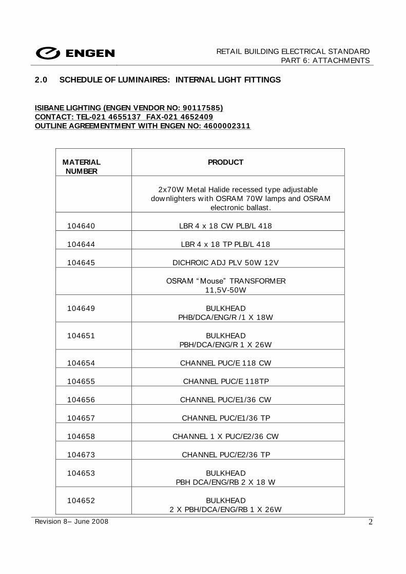
RETAIL BUILDING ELECTRICAL STANDARD
PART 6: ATTACHMENTS
Revision 8– June 2008
2
2.0 SCHEDULE OF LUMINAIRES: INTERNAL LIGHT FITTINGS
ISIBANE LIGHTING (ENGEN VENDOR NO: 90117585)
CONTACT: TEL-021 4655137 FAX-021 4652409
OUTLINE AGREEMENTMENT WITH ENGEN NO: 4600002311
MATERIAL
NUMBER
PRODUCT
2x70W Metal Halide recessed type adjustable
downlighters w ith OSRAM 70W lamps and OSRAM
electronic ballast.
104640
LBR 4 x 18 CW PLB/L 418
104644
LBR 4 x 18 TP PLB/L 418
104645
DICHROIC ADJ PLV 50W 12V
OSRAM “ Mouse” TRANSFORMER
11,5V-50W
104649
BULKHEAD
PHB/DCA/ENG/R /1 X 18W
104651
BULKHEAD
PBH/DCA/ENG/R 1 X 26W
104654
CHANNEL PUC/E 118 CW
104655
CHANNEL PUC/E 118TP
104656
CHANNEL PUC/E1/36 CW
104657
CHANNEL PUC/E1/36 TP
104658
CHANNEL 1 X PUC/E2/36 CW
104673
CHANNEL PUC/E2/36 TP
104653
BULKHEAD
PBH DCA/ENG/RB 2 X 18 W
104652
BULKHEAD
2 X PBH/DCA/ENG/RB 1 X 26W
RETAIL BUILDING ELECTRICAL STANDARD
PART 6: ATTACHMENTS
Revision 8– June 2008
3
104659
DOWNLIGHT PDL FCR 2 X 26W
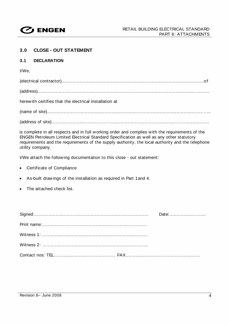
RETAIL BUILDING ELECTRICAL STANDARD
PART 6: ATTACHMENTS
Revision 8– June 2008
4
3.0 CLOSE - OUT STATEMENT
3.1 DECLARATION
I/We,
(electrical contractor).....................................................................................................o f
(address)................................................................................................................. .........
.
herew ith cert if ies that the electrical installat ion at
(name of site)............................................................................................................... .....
(address of site)........................................ ........................................................................
is complete in all respects and in full working order and complies w ith the requirements of the
ENGEN Petroleum Limited Electrical Standard Specif icat ion as well as any other statutory
requirements and the requirements of the supply authority, the local authority and the telephone
ut ility company.
I/We attach the follow ing documentation to this close - out statement:
Cert if icate of Compliance
As-built draw ings of the installat ion as required in Part 1and 4.
The attached check list.
Signed:................................................................................. Date:..........................
Print name:................................................................ ..........
Witness 1: ...........................................................................
Witness 2: ...........................................................................
Contact nos: TEL............................................ FAX.....................................................
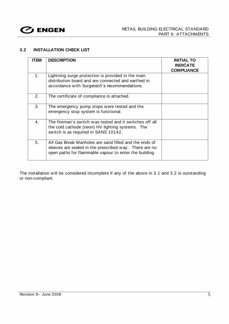
RETAIL BUILDING ELECTRICAL STANDARD
PART 6: ATTACHMENTS
Revision 8– June 2008
5
3.2 INSTALLATION CHECK LIST
ITEM DESCRIPTION INITIAL TO
INDICATE
COMPLIANCE
1. Lightning surge protect ion is provided in the main
distribut ion board and are connected and earthed in
accordance w ith Surgetech‟s recommendations.
2. The cert if icate of compliance is attached.
3. The emergency pump stops were tested and the
emergency stop system is functional.
4. The f ireman' s sw itch w as tested and it sw itches off all
the cold cathode (neon) HV light ing systems. The
sw itch is as required in SANS 10142.
5. All Gas Break Manholes are sand f illed and the ends of
sleeves are sealed in the prescribed way. There are no
open paths for f lammable vapour to enter the building.
The installat ion w ill be considered incomplete if any of the above in 3.1 and 3.2 is outstanding
or non-compliant.

RETAIL BUILDING ELECTRICAL STANDARD
PART 6: ATTACHMENTS
Revision 8– June 2008
6
3.3 ACKNOWLEDGEMENT OF CLOSE-OUT
I have satisf ied myself that the items listed in the close-out statement by
(contractor)...................................... ..................................................................... for the
(installat ion)............................................................................................................... ...
are included and accept the same on behalf of ENGEN.
THE DOCUMENTATION WAS LODGED AS FOLLOWS:
. Cert if icate of Compliance :....................................................................................
. As-built draw ings :.................................................................... ................
Check list :............................................................................................................
Signed: ..........................................................................................
Print name: .....................................................................................
Date: ........................................