Embed Size (px)
DESCRIPTION
response
Citation preview
Response mitigation on the offshore floating
platform system with tuned liquid column damper
H.H. Lee *, S.-H. Wong, R.-S. Lee
Department of Marine Environment and Engineering, National Sun Yat-sen University,
Kaohsiung 804, Taiwan, ROC
Received 21 March 2005; accepted 12 June 2005
Available online 1 December 2005
Abstract
In this study a typical tension-leg type of floating platform incorporated with the tuned liquid
column damper (TLCD) device is studied. The purpose is to find an effective and economic means to
reduce the wave induced vibrations of the floating offshore platform system. The floating offshore
platform has been widely applied for the offshore exploitation such as operation station, cross-strait
bridges, floating breakwater and complex of the entertainment facilities. For offshore platform being
employed as a public complex the stability and comfort to stay will be the major concern besides the
safety requirement. Therefore, how to mitigate the vibration induced from waves and similar
environmental loading becomes an important issue. The TLCD system utilizing the water sloshing
power to reduce the vibration of the main structure, a newly developed device that could effectively
reduce the vibrations for many kinds of structure is the first-time employed in the floating platform
system. In both the analytical and experimental results it is found that the accurately tuned TLCD
system could effectively reduce the dynamic response of the offshore platform system in terms of the
vibration amplitude and the resonant frequency.
q 2005 Elsevier Ltd. All rights reserved.
Keywords: Tuned liquid column damper; Offshore structure; Response mitigation; Tension leg platform system
1. Introduction
A study on the vibration mitigation for an offshore floating platform system of tension leg
type subjected to the surge motion is presented in this study when the platform is incorporated
with the tuned liquid column damper (TLCD) device. The offshore platform has been widely
Ocean Engineering 33 (2006) 1118–1142
www.elsevier.com/locate/oceaneng
0029-8018/$ - see front matter q 2005 Elsevier Ltd. All rights reserved.
doi:10.1016/j.oceaneng.2005.06.008
* Corresponding author.

H.H. Lee et al. / Ocean Engineering 33 (2006) 1118–1142 1119
applied as the operation station for the offshore exploitation, floating breakwater, offshore
fish-farming platform and combination of the entertainment facilities. When the platform
located in the offshore marine environment many kinds of loading may exert on the platform
structure and result in tremendous vibration and instability. These vibrations not only
gradually damage the platform structural system but also cause the problem of uncomfortable
environment of staying. Therefore, the vibration stability of the platform becomes the major
concern besides the safety requirement particularly when the platform systems are being used
for public entertainment purposes. It is always a challenging task to try to reduce the vibration
induced from wave, flow or wind loading because of the difficulties of accurately monitoring
the platform motion and lack of the appropriate mitigation device applied to the system.
To monitor the platform motions many researches have been carried out based on the
platform type. For the tension-leg type platform system, a rather new development for the
offshore deep-sea exploitation, researches could be found in two major categories in
general such as those mainly focused on the wave-structure interaction problems and the
researches on the nonlinear effect of small body on the platforms. The problems of
structure-wave interactions were studied as early as 1970s in numerical method (Mei,
1978; Yamamoto et al., 1982), and also investigated in experimental test (Yamamoto
et al., 1982). Without considering the interaction between the structure and the wave,
numerical techniques were basically utilized such as the study on the coupled 6-degree
freedom of rigid-body motion for the platform (Jain, 1997) and the simulation for the
platform system by using a three-dimension beam element (Chatterjee et al., 1997).
While many efforts have been put in the study of the platform and waves, rare attention is
being paid on the vibration mitigation. In this study, however, the mitigation of vibration for
the platform system will be the purpose when the tuned liquid column damper (TLCD) is
incorporated in the platform system. The floating platform system employed for the study is
a platform supported by pontoons and anchored with pre-stressed tethers. When the
pontoon, the barge under the platform that provides the buoyant force has diameters smaller
than one fifth of the wavelength generally the wave structure interactions can be ignored.
Therefore, the small body in the waves will be assumed and the related theories of the waves
on the small body will be applied for the behavior of the platform system subjected to waves.
The TLCD system is a newly developed device by utilizing the water sloshing power to
reduce the vibrations of the main structure induced from the environmental loading. This
device has been widely applied to the traditional civil structures such as the application to
the structures in Sakitama Bridge and Shin Yokohama Prince Hotel in Japan (Fujino and
Sun, 1993) and the effectiveness for the vibration reduction was also verified. However,
the application of the TLCD to the offshore structural system has not been found in the
references yet. The TLCD was extended from the tuned liquid damper (TLD) device,
which has been widely discussed and studied in the late 1980s and early 1990s (Fujino
et al., 1988, 1992; Chaiseri et al., 1989). The TLCD is a U-shape tube-like device that
consists of water or similar liquid. The liquid passing through a small orifice opened at the
center of cross section of the tube causes the head loss of the liquid and then reduces
the vibration of the main structure attached. The head loss of the liquid induced from the
orifice at the cross section that has damping effect was firstly studied by Sakai et al. (1989).
In the study for the application of the TLCD system to the tower type structure Balendra
et al. (1995) provided a relationship between the tower height and the opening ratio for
H.H. Lee et al. / Ocean Engineering 33 (2006) 1118–11421120
the orifice. The application of TLCD system to the multi-degree-of-freedom structures
was also studied by Won et al. (1996) by using random vibration analysis for the
earthquake excitation.
Recently many improvement ideas for the TLCD system have been proposed such as
the variable orifice system or so called pressure control mechanism (Kareem et al., 1995)
and the studies on the characteristics of variable cross section between the horizontal and
vertical tube (Hichhock et al., 1997a,b; Gao and Kwok, 1997). In Gao and Kwok (1997)
study they found that the increase of the cross section of horizontal tube might reduce the
liquid column in vertical tube and the optimal parameters could be obtained to reduce the
amplification factor when the structure subjected to a harmonic vibration.
The purpose of this study is to investigate the vibration mitigation of a tension leg
offshore platform system of pontoon type when incorporated with the TLCD device and
subjected to surge wave motion. The stochastic analytical method in the frequency domain
was utilized and due to this the linearization scheme for the system was also applied. Since
the pontoon under the platform was small enough when compared to the wavelength the
Morison’s equation for small body was used for the calculation of wave forces. Numerical
examples were carried out and the results were discussed focusing on the platform motion
when subjected to waves of a range of periods. Along with the analysis, the parameter
effect such as the draft and the size of the pontoons for the floating platform was also
studied and discussed. It was found from the results that the accurately tuned TLCD
system could effectively reduce the dynamic response of the offshore platform system in
terms of the vibration amplitude and the resonant frequency. A preliminary experimental
test was also carried out for the feasibility study of the TLCD device applied to the floating
offshore platform. It was also found from the experimental test that after appropriate
design the TLCD could effectively suppress the wave-induced vibration.
2. Equation of motion for the platform with TLCD
For the TLCD device installed in a tension leg platform structure it is assumed that
there is no relative motion between the structure and the TLCD and when the structure
vibrates the liquid inside TLCD also sloshes. Fig. 1 is a typical tension leg strained
platform of pontoon type of two-dimension combined with the TLCD device that is
illustrated in Fig. 2, where a U-shape tube-like container has liquid inside and an orifice is
opened at the center of the cross section of the horizontal tube. The equation of motion for
the liquid in the tube is presented as (Sakai et al., 1989)
rdAdLd€H C
1
2rdAdhdj _Hj _H C2rdAdgH ZKrdAdBd
€X (1)
where hd is the factor of the head loss of the liquid, H _H and €H are the displacement,
velocity and the acceleration of the liquid in the vertical tube respectively. rd is the density
of the liquid in the tube. Ad is the inner area of tube cross section while Bd and Ld are the
length of horizontal portion and the total length of the tube occupied by liquid,
respectively. When incorporated with the TLCD device, in considering the 2-dimensional,
3-degree of freedom motion (surge, heave and pitch), the equation of motion for this

DECK
FLOATING BARREL
TENSION LEG
WAVESWL
Ls
TLCD
d D
X
Y
Fig. 1. Offshore floating platform system with TLCD device.
H.H. Lee et al. / Ocean Engineering 33 (2006) 1118–1142 1121
pontoon type platform system incorporated with the TLCD device may be presented as
M €X CCX_X CKXX Z Fw KrdAdBd
€H KrdAdLd€X (2)
M €Y CCY_Y CKY Y ZK2rdAdH €H KrdAdLd
€Y (3)
Mq€q CCq
_q CKqq Z ½2rdAdgH CrdAdðLdKBdÞ €H �1
2Bd C �h
� �C
1
2rdAdhdj _Hj _H �h
(4)
where X, Y and q are motions corresponding to surge, heave and pitch of the platform. M is
the mass of the platform system and Mq is the mass moment of inertia corresponding to
pitch motion while CX, CY and Cq are corresponding damping coefficients. Fw is the wave
force depends on both the waves and the structures submerged in the wave. KX, KY and Kq
are the stiffness corresponding to the surge, heave and pitch motion of the platform
X
H
H
Ld
orifice
ρd, Ad
Bd
Fig. 2. Illustration for the TLCD device.

H.H. Lee et al. / Ocean Engineering 33 (2006) 1118–11421122
respectively. �h is the distance from the center of mass moment of inertia to the bottom of
the structure.
It is noticed that except for Eq. (2) there are several nonlinear terms in above equations.
In the left-hand side of Eq. (1) and right hand side of Eq. (4) the nonlinear terms _Hj _Hj are
induced from the drag motion of the liquid in the tube. Since, a spectral analysis will be
employed in this study the technique of equivalent linearization (Wen, 1980; Xu et al.,
1992) is adopted here for those nonlinear terms in the equations. Assuming zero-mean
stationary Gaussian process for the velocity _H, the equation of motion for the liquid is
rewritten as
md€H Ccd
_H Cu2dmdH ZK
Bd
Ld
� �md
€X (5)
where the mass mdZrdAdLd and natural frequency udZffiffiffiffiffiffiffiffiffiffiffi2g=Ld
pwith g the gravitational
constant. The equivalent damping coefficient cd is obtained through the minimization of
the error 3 between the exact nonlinear drag damping and the equivalent one as
3 Zmdhd
2Ld
� �j _Hj _HKcd
_H (6)
After carrying out the minimization for this error the equivalent damping coefficient is
as
cd Z
ffiffiffiffi2
p
rrdAdhds _H (7)
where s _H is the standard deviation of the velocity of the liquid in the tube. Alternatively
Eq. (5) may be rewritten as
md€H Ccd
_H CkdH ZKmdad€X (8)
where kdZ2rdAdg is the stiffness coefficient for the TLCD system and adZBd/Ld is the
width-length ratio between the horizontal portion and the total length of liquid column. By
employing the same technique the first term at right-hand side of Eq. (3) can be written as
2rdAdH €H Z Q €H (9)
where QZ4ffiffiffiffiffiffiffiffi2=p
prdAdsH and sH is the standard deviation of the liquid displacement. Now
by substituting Eq. (9) back into Eq. (3) and employing the equivalent damping technique
of Eq. (7) for the nonlinear drag term in Eq. (4), equations of heave and pitch motion are
rewritten into
M €Y CCY_Y CKY Y ZKQ €H KrdAdLd
€Y (10)
Mq€q CCq
_q CKqq Z 2rdAdgð �h CBd=2ÞH Ccd�h _H C ½rdAdðLdKBdÞð �h CBd=2Þ� €H
(11)
Combining Eq. (8) with Eqs. (2), (10) and (11), equations of the motion for the
floating platform incorporated with TLCD subjected to wave force are given in

H.H. Lee et al. / Ocean Engineering 33 (2006) 1118–1142 1123
a matrix form as
md rdAdBd 0 0
rdAdBd M Cmd 0 0
Q 0 M Cmd 0
KrdAdBdðLdKBdÞð1=2Bd C �hÞ 0 0 Mq
266664
377775
€H
€X
€Y
€q
8>>>>><>>>>>:
9>>>>>=>>>>>;
C
cd 0 0 0
0 CX 0 0
0 0 CY 0
Kcd�h 0 0 Cq
266664
377775
_H
_X
_Y
_q
8>>>>><>>>>>:
9>>>>>=>>>>>;
C
kd 0 0 0
0 KX 0 0
0 0 KY 0
K2rdAdgð �h CBd=2Þ 0 0 Kq
266664
377775
H
X
Y
q
8>>>><>>>>:
9>>>>=>>>>;
Z
0
Fw
0
0
8>>>><>>>>:
9>>>>=>>>>;
(12)
Stiffness KX, KY and Kq corresponding to the surge, heave and pitch motion of the
platform after modified from Jain (1997) and Lee et al. (1999a) for uncoupled motions
can be presented as
KX Z 2K* (13)
KY Z 2rgG C2AE
[(14)
Kq Z 2K� �h2C2
AE
[L2
s C1
2rgGL2
s (15)
where r, g and G are the water density, gravity acceleration and the cross section area of
the submerged pontoon respectively. d0 and d1 is the draft of the structure before and
after applying the pre-tension force. A and E are the section area and young’s modulus of
the tether respectively, [ the tether length and LS is the platform width. It is noticed that
the buoyancy difference, angle difference and the elongation of the tether were all taken
into accounts for the rotational stiffness component corresponding to the pitch motion of
the platform. K* is the equivalent stiffness of the platform system induced by one of the
pretension tethers (Lee et al., 1999b; Lee and Wang, 2000) related to the material
properties and dimension of the tethers, as
K� ZrgG
[ðd1Kd0Þ
m
m C1
� �(16)

H.H. Lee et al. / Ocean Engineering 33 (2006) 1118–11421124
where m is the proportional stiffness parameter defined as the ratio between the tether
stiffness and the buoyancy force of the pontoon structure submerged in the water of unit
depth.
The excitation force induced from the surge motion of wave exerting on the unit length
of pontoon member is given by a modified Morison’s equation (Newman, 1977; Isaacson,
1979) as
FWðtÞ Z rCm
pD2
4_uKrCa
pD2
4€X C
1
2rCdDjuK _XjðuK _XÞ (17a)
or alternatively, after employing the linearization technique for the nonlinear drag term, as
FWðtÞ Z rCmG _uKrCaG €X C1
2rCdDjujuK
1
2rCdD2hjuji _X (17b)
where hjuji is the time average of the fluid velocity u, r the water density and CaZCmK1 is
the coefficient of added mass while Cm is the inertia coefficient, Cd the drag coefficient and
D is the dimension of the structural member normal to the incoming wave. Now after the
integration of the wave force on the unit pontoon the equation of motion accounting for the
total wave force, added mass and drag effect on the damping can further be presented as
md rdAdBd 0 0
rdAdBd m� Cmd 0 0
Q 0 m* Cmd 0
KrdAdðLdKBdÞð �h C1=2BdÞ 0 0 Mq
266664
377775
€H
€X
€Y
€q
8>>>>><>>>>>:
9>>>>>=>>>>>;
C
cd 0 0 0
0 C�X 0 0
0 0 C�Y 0
Kcd�h 0 0 C�
q
2666664
3777775
_H
_X
_Y
_q
8>>>>><>>>>>:
9>>>>>=>>>>>;
C
kd 0 0 0
0 KX 0 0
0 0 KY 0
K2rdAdgð �h CBd=2Þ 0 0 Kq
266664
377775
H
X
Y
q
8>>>><>>>>:
9>>>>=>>>>;
Z
0
F
0
0
8>>>><>>>>:
9>>>>=>>>>;
(18)
where m*ZMCrCac, with c the submerged volume of pontoon. For the simplicity of
the damping effect C*Z2m*zun while the total wave force is obtained through integration
over submerged depth of the pontoon as
FðtÞ Z1
2rDCd
ðd1
d0
ujuj ds CrGCm
ðd1
d0
_u ds (19)

H.H. Lee et al. / Ocean Engineering 33 (2006) 1118–1142 1125
3. Response spectral density for the platform with TLCD
Now with the equation of motion modified as the linear form we may further find the
complex frequency response function for the floating platform incorporated with TLCD
and then solve for the response spectral density. When the wave force is harmonic the
response of the platform and the liquid motion in the tube could be assumed to be
harmonic. The complex frequency response function for the liquid column in the tube is
obtained as
H0 Zu2rdAdBd
ðKu2md C iucd C2rdAdgÞF0HXðuÞ (20)
where HX(u) is the complex frequency response function corresponding to the surge
motion of the platform and F0 is the amplitude of the harmonic wave force. The complex
frequency response function corresponding to the surge, heave and pitch of the platform
can further be written as
HXðuÞ Z1
Kðm� CmdÞu2 C iuCX CKX K
u4r2dA2
dB2
d
ðKmdu2CiucdC2rdAdgÞ
h i (21)
HY ðuÞ ZQu4rdAdBd
ðKu2md C iucd C2rdAdgÞ½Ku2ðm� CrdAdLdÞC iuCY CKY �HXðuÞ
(22)
HqðuÞ Zu2rdAdBd Ku2rdAdðLdKBdÞ
12
Bd C �h� �
C2rdAdg �h C iu �hcd
� �ðKu2mq C iuCq CKqÞðKu2md C iucd C2rdAdgÞ
HXðuÞ
(23)
According to the spectral analytical scheme the response spectrum of the system may
be obtained through the cross of the system transfer function and the spectrum of the wave
exerting force such as
SXðuÞ Z jHXðuÞj2SFðuÞ (24)
SY ðuÞ Z jHY ðuÞj2SFðuÞ (25)
SqðuÞ Z jHqðuÞj2SFðuÞ (26)
where SX(w), SY(w) and Sq(w) are the spectrum of the structural response and SF(w) is the
wave force spectrum while jHX(u)j2 the transfer function of the system is obtained from
the complex frequency response function. The wave force spectrum is obtained from the
wave spectrum when the Morison’s equation for the waves on small body was employed
and statistical independence between the velocity and acceleration was assumed

H.H. Lee et al. / Ocean Engineering 33 (2006) 1118–11421126
(Borgman, 1967; Sarpkaya and Isaacson, 1981) and presented as
SFðuÞ Z ShðuÞ8
p
uKd
sin hðkdÞ
ðd
0
suðsÞcos hðksÞds
24
35
2
Cu4K2
i
k2
8><>:
9>=>; (27)
where su is the standard deviation of fluid velocity, k is the wave number, sZyCd the
depth of the water from the free surface d. Kd and Ki are given by KdZ0.5rDCd and KiZrGCm Sh(u) is the wave spectrum. In this study a typical Pierson–Moskowitz spectrum
(Pierson and Moskowitz, 1964) is applied and given as
ShðuÞ Z2pag2
u5exp
KB
u4
� �(28)
where aZ8.1!10K3 is the Philip’s constant and BZ0.74 g/U with the characteristic wind
speed U over the water. By substituting Eqs. (27) and (28) into Eqs. (24)–(26) the response
spectra of floating platform incorporated with the TLCD are obtained.
4. Optimal design for the TLCD incorporated in the platform system
To have a good performance for this special design platform system incorporated with
the TLCD an accurate tuning-up process for the parameters of TLCD corresponding to the
structural characteristics is required that is so called optimal design process. Firstly the
parameters of TLCD that may have significant influence on the system behavior are
selected. According to previous studies the dimensions of the TLCD such as Ld, Bd and
area of cross section Ad are influenced by two important parameters, namely, the mass
ratio between TLCD and the main structure and the coefficient of the head loss of the
liquid. These parameters must be determined carefully so that the optimum performance
can be achieved. The coefficient of the liquid head loss is related to the opening ratio of the
orifice, the characteristics of the main structure and the setting-up conditions of the TLCD.
Fig. 3. The Pierson–Moskowitz wave spectrum.

0.00E+002.00E+034.00E+036.00E+038.00E+031.00E+041.20E+041.40E+041.60E+041.80E+04
0 0.05 0.1 0.15 0.2 0.25 0.3 0.35 0.4
Frequency (Hz)
Rep
onse
spe
ctru
m (
m2 -
sec) B=3
B=4B=5
(a)
B=3B=4B=5
0.00E+00
5.00E+00
1.00E+01
1.50E+01
2.00E+01
2.50E+01
0 0.2 0.4 0.6 0.8 1 1.2 1.4
Frequency (Hz)
Res
pons
e sp
ectr
um (
m2 -
sec.
)
(b)
B=3B=4B=5
0.00E+00
2.00E-03
4.00E-03
6.00E-03
8.00E-03
1.00E-02
1.20E-02
1.40E-02(c)
0 0.5 1 1.5 2 2.5 3 3.5 4
Frequency (Hz)
Rot
aion
al r
espo
nse
spec
trum
Fig. 4. Spectral densities of the platform responses without TLCD devices for various pontoon dimensions. (a)
Response in X-direction (surge motion); (b) response in Y-direction (heave motion); (c) response in rotation (pitch
motion).
H.H. Lee et al. / Ocean Engineering 33 (2006) 1118–1142 1127
By ignoring the high frequency mode and taking only the surge motion from the
equation of motion of the platform system incorporated with TLCD as shown in Eq. (19),
under the Gaussian white noise type of excitation the variance of the response spectrum
can be written as (Crandal and Mark, 1973, modified by Chang et al., 1998).
s2X Z pSF
ðb20=a0Þða2a3 Ka1a4ÞCa3ðb
21 K2b0b2ÞCa1ðb
22 K2b1b3ÞC ðb2
3=a4Þða1a2 Ka0a3Þ� �
a1ða2a3 Ka1a4ÞKa0a23
� �(29)
where SF is the spectral density of the exciting force while as and bs are parameters related
to the structural properties of the platform and also the TLCD parameters such as the

0.00E+00
5.00E+02
1.00E+03
1.50E+03
2.00E+03
2.50E+03
0 0.1 0.2 0.3 0.4 0.5 0.6
Frequency (Hz)
Res
pons
e sp
ectr
um (
m2 -
sec)
No Damper
With TLCD
(a)
No TLCD
With TLCD
0.00E+00
5.00E-01
1.00E+00
1.50E+00
2.00E+00
2.50E+00
3.00E+00
0 0.5 1 1.5
Frequency (Hz)
Res
pons
e Sp
ecru
m (
m2 -
sec)
(b)
No TLCD
With TLCD
0.00E+00
2.00E-03
4.00E-03
6.00E-03
8.00E-03
1.00E-02
1.20E-02(c)
0 1 2 3 4
Frequency (Hz)
Rot
atio
nal r
espo
nse
spec
trum
Fig. 5. Comparison of spectral responses for the platform with and without TLCD devices corresponding to
variation of pontoon dimension (3m ). (a) Response comparison in X-direction (surge motion); (b) response
comparison in Y-direction (heave motion); (c) response comparison in rotation (pitch motion).
H.H. Lee et al. / Ocean Engineering 33 (2006) 1118–11421128
width-length ratio of the liquid ad and the damping coefficient cd as:
a0 Z KXkd; a1 Z KXcd CkdC�X ; a2 Z ðm� CmdÞkd CmdKX CC�
Xcd;
a3 Z ðm� CmdÞcd CmdC�X ; a4 Z ðm� CmdÞmdKm2
da2d; b0 Z kd;
b1 Z cd; b2 Z md; b3 Z 0
(30)

0.00E+00
2.00E+03
4.00E+03
6.00E+03
8.00E+03
1.00E+04
1.20E+04
1.40E+04
1.60E+04
1.80E+04
0 0.1 0.2 0.3 0.4 0.5
Frequency (Hz)
Res
pons
e sp
ectr
um(m
2 -se
c)
No Damper
With TLCD
(a)
0.00E+001.00E+002.00E+003.00E+004.00E+005.00E+006.00E+007.00E+008.00E+009.00E+001.00E+01
0 0.5 1 1.5
Frequency (Hz)
Res
pons
e sp
ectr
um (
m2 -
sec) No TLCD
With TLCD
(b)
No TLCDWith TLCD
0.00E+00
1.00E-03
2.00E-03
3.00E-03
4.00E-03
5.00E-03
6.00E-03
7.00E-03(c)
0 1 2 3 4
Frequency (Hz)
Rot
atio
nal r
espo
nse
spec
trum
Fig. 6. Comparison of spectral responses for the platform with and without TLCD devices corresponding to
variation of pontoon dimension (4 m). (a) Response comparison in X-direction (surge motion); (b) response
comparison in Y-direction (heave motion); (c) response comparison in rotation (pitch motion).
H.H. Lee et al. / Ocean Engineering 33 (2006) 1118–1142 1129
Assuming that the standard deviation of the flow velocity of the liquid in the tube is
constant and ignoring the structural damping the optimal total length Ld and the damping
coefficient cd can be obtained through the differentiation of the variance of the response
spectrum and given as
LOPT Z2gm�
KX
(31)

0.00E+00
2.00E+03
4.00E+03
6.00E+03
8.00E+03
1.00E+04
1.20E+04
1.40E+04
1.60E+04
0 0.1 0.2 0.3 0.4 0.5
Frequency (Hz)
Res
pons
e sp
ectr
um (
m2 -
sec) No Damper
With TLCD
(a)
0.00E+00
5.00E+00
1.00E+01
1.50E+01
2.00E+01
2.50E+01
0 0.5 1 1.5
Frequency (Hz)
Res
pons
e sp
ectr
um (
m2 -
sec) No TLCD
With TLCD
(b)
No TLCD
With TLCD
0.00E+00
2.00E-03
4.00E-03
6.00E-03
8.00E-03
1.00E-02
1.20E-02
1.40E-02(c)
0 1 2 3 4
Frequency (Hz)
Rot
atio
nal r
espo
nse
spec
trum
Fig. 7. Comparison of spectral responses for the platform with and without TLCD devices corresponding to
variation of pontoon dimension (5 m). (a) Response comparison in X-direction (surge motion); (b) response
comparison in Y-direction (heave motion); (c) response comparison in rotation (pitch motion).
H.H. Lee et al. / Ocean Engineering 33 (2006) 1118–11421130
cOPT Z md mda2du2
d Cu2n C
u4d
u2n
K2u2n
� �1=2
(32)
where mdZmd/m* is the mass ratio, un and ud is the natural frequency of the platform in
surge motion and the TLCD respectively. When the natural frequencies of the TLCD and
the platform in surge motion are the same thus in the resonance the damping effect induced
by the TLCD device achieves the optimal performance and at this resonant stage the loss

73.2
99.7
0
73.367
81.5 84.4
6755.4
37.1
94.5
55.3
0
20
40
60
80
100
120
Surge Heave Pitch Total
Corresponding platform motion
Dis
sipa
ted
ener
gy (
%)
B=3 B=4 B=5
Fig. 8. Comparison of the energy dissipation for various pontoon dimension.
H.H. Lee et al. / Ocean Engineering 33 (2006) 1118–1142 1131
of the water head is optimum given by
hOPT Z
ffiffiffiffiffiffiffiffiffiffiffiffiffiffiffipmdKX
2ðm�Þ2
rBd
s _H(33)
When the structure is under the same exciting force the mitigation effect of TLCD is
determined by its effective damping presented as (Sun et al., 1993)
ze ZpSF
2u2nðm
�Þ2s2X
(34)
When this effective damping ratio is determined the area of the cross section of the tube
is obtained by substituting Eq. (28) into Eq. (32) and after rearrangement it is given as
Ad ZLdðm
� CmdÞ
B2rd
K2zeu3
nðm�Þ2 b2
0=a0
� �a2a3 Ca3 b2
1K2b0b2
� �Ca1b2
2Ka1a2a3 Ca0a23
� �B2
drd 2zeu3nðm
�Þ2 b20=a0
� �a1Ka2
1
� �� �(35)
With Eqs. (29), (31) and (33) the optimal parameters for the TLCD such as the total
liquid length Ld, loss of the water head hd and cross section area Ad are determined and
then the optimal mitigation for the platform is also obtained. However due to the
interdependence of the standard deviation sH of the liquid velocity and the damping
coefficient as shown in Eq. (7) and then Eq. (31) the iteration scheme for the convergence
is needed for the solution.

H.H. Lee et al. / Ocean Engineering 33 (2006) 1118–11421132
5. Numerical results and discussion
Numerical examples for the offshore floating platform of pontoon type incorporated
with the TLCD system were carried out in this section. The investigation was focused on
the spectral density of the response of the platform and the effectiveness of mitigation
when the platform system was subjected to waves with various periods. The influence on
the mitigation effect from the pontoon diameter, draft and mass of the platform structure
was also examined. A typical Pierson–Moskowitz wave spectrum to simulate the wave
condition was adopted in this study and presented as Fig. 3.
0.00E+00
2.00E+03
4.00E+03
6.00E+03
8.00E+03
1.00E+04
1.20E+04
1.40E+04
1.60E+04
0 0.1 0.2 0.3 0.4 0.5
Frequency (Hz)
Rep
onse
spe
trum
(m
2 -se
c)
D1=2
D1=3
D1=4
D1=2
D1=3
D1=4
0.00E+00
5.00E+00
1.00E+01
1.50E+01
2.00E+01
2.50E+01
0 0.2 0.4 0.6 0.8 1
Frequency (Hz)
Res
pons
e sp
ectr
um (
m2 -
sec)
D1=2
D1=3
D1=4
0.00E+00
2.00E-03
4.00E-03
6.00E-03
8.00E-03
1.00E-02
1.20E-02
1.40E-02
(a)
(b)
(c)
0 1 2 3 4Frequency (Hz)
Rot
atio
nal r
espo
nse
spec
trum
Fig. 9. Spectral densities of the platform responses without TLCD devices for various pontoon drafts. (a)
Response in X-direction (surge motion); (b) response in Y-direction (heave motion); (c) response in rotation (pitch
motion).

0.00E+00
2.00E+03
4.00E+03
6.00E+03
8.00E+03
1.00E+04
1.20E+04
1.40E+04
1.60E+04
0 0.1 0.2 0.3 0.4 0.5
Frequency (Hz)
Res
pons
e sp
ectr
um (
m2 -
sec)
No TLCD
With TLCD
(a)
No TLCD
With TLCD
0.00E+00
5.00E+00
1.00E+01
1.50E+01
2.00E+01
2.50E+01
0 0.2 0.4 0.6 0.8 1
Frequency (Hz)
Res
pons
e sp
ectr
um (
m2 -
sec)
(b)
No TLCD
With TLCD
0.00E+00
2.00E-03
4.00E-03
6.00E-03
8.00E-03
1.00E-02
1.20E-02
1.40E-02(c)
0 1 2 3 4
Frequency (Hz)
Rot
atio
nal r
espo
nse
spec
trum
Fig. 10. Comparison of spectral responses for the platform with and without TLCD devices corresponding to
variation of pontoon draft (2 m). (a) Response comparison in X-direction (surge motion); (b) response comparison
in Y-direction (heave motion); (c) response comparison in rotation (pitch motion).
H.H. Lee et al. / Ocean Engineering 33 (2006) 1118–1142 1133
5.1. Mitigation effect with various pontoon diameters
Since the pontoons attached under the deck provide the buoyant force for the platform
and also take the pounding waves their dimensions will have influence on the initial draft,
the added mass and the wave force exerted on the platform system. Therefore it is interested
to examine the mitigation effect when the parameters of TLCD are designed optimally
corresponding to the pontoon diameter variation. Presented in Fig. 4(a, b and c) are spectral
densities of the platform responses in X-, Y- and rotational direction corresponding to the
frequency of wave exerting on the platform without TLCD device. These figures showed

H.H. Lee et al. / Ocean Engineering 33 (2006) 1118–11421134
that corresponding to the increase of the pontoon dimensions the response of the platform is
increased generally and shifted to a higher resonant frequency while for the heave motion
the response shifted to a lower frequency range. Figs. 5–7 are the comparisons of the
responses for the pontoon-type platform before and after the installation of a TLCD device,
corresponding to various pontoon dimensions of 3, 4 and 5 m, respectively. In the figure, (a),
(b) and (c) indicated the response of X-, Y- and rotational motion. It is observed from part (a)
of Figs. 5–7 that the TLCD could effectively reduce the response of the platform in surge
motion as the peak value is dropped while the resonant frequency almost remains
0.00E+00
1.00E+03
2.00E+03
3.00E+03
4.00E+03
5.00E+03
6.00E+03
7.00E+03
8.00E+03
9.00E+03
0 0.1 0.2 0.3 0.4 0.5
Frequency (Hz)
Res
pons
e sp
etru
m (
m2 -
sec)
No TLCD
With TLCD
(a)
No TLCD
With TLCD
0.00E+002.00E+004.00E+006.00E+008.00E+001.00E+011.20E+011.40E+011.60E+011.80E+012.00E+01
0 0.2 0.4 0.6 0.8 1
Frequency (Hz)
Res
pons
e sp
ectr
um (
m2 -
sec)
(b)
No TLCD
With TLCD
0.00E+00
2.00E-03
4.00E-03
6.00E-03
8.00E-03
1.00E-02
1.20E-02(c)
0 1 2 3 4
Frequency (Hz)
Rot
atio
nal r
espo
nse
spec
trum
Fig. 11. Comparison of spectral responses for the platform with and without TLCD devices corresponding to
variation of pontoon draft (3 m). (a) Response comparison in X-direction (surge motion); (b) response comparison
in Y-direction (heave motion); (c) response comparison in rotation (pitch motion).

H.H. Lee et al. / Ocean Engineering 33 (2006) 1118–1142 1135
unchanged. However, for the heave motion the response was dropped in some cases such as
Figs. 5(b) and 6(b) but for case as Fig. 7(b) the peak remained about the same while the
resonant frequency was shifted to a much lower range in all three cases. For the rotational
motion the TLCD device mostly reduced the response amplitude as indicated in part (c) of
Figs. 6 and 7 while the resonant frequency was not affected.
The mitigation effect of the platform incorporated with the TLCD may be represented
as dissipated energy through the integration for the spectral density of the response. Fig. 8
is the comparison for the effectiveness of the TLCD for various pontoon dimensions
represented as the percentage of the energy dissipated corresponding to the surge motion
(X-direction), heave motion (Y-direction), pitch motion and finally the total amount of
dissipated energy were also illustrated. It was found in this comparison that although the
energy dissipated in the heave and pitch motion is in a large variance it would still be a
small percentage for the total amount of energy. The most paramount energy is found in
the surge motion and thus overall, the energy is mostly dissipated in the surge motion. The
amount of the energy being dissipated is decreased with respect to the increase of the
pontoon dimension from 73 down to 55%. This means that the vibration mitigation
effectiveness (mostly for the surge and heave motion) reduces corresponding to the
increase of the pontoon dimension even though the suppression on the pitch motion seems
to be more effective correspondingly.
5.2. Mitigation effect with various pontoon draft
When the initial pontoon draft varies the pretension force of the tether and the wave
force will be influenced. Therefore it is interested to know the variation of the pontoon
draft on the mitigation effect induced from the TLCD. Fig. 9(a, b and c) are spectral
densities of the platform responses in X-, Y- and rotational direction corresponding to
the frequency of wave exerting on the platform without TLCD device while draft of the
pontoon is varied from 2 to 4 m. It is observed that corresponding to the increase of the
pontoon draft the response of the platform is reduced. The resonant frequency shifted to a
Surge Heave Pitch Total
Corresponding platform motion
0
20
40
60
80
100
120
Dis
sipa
ted
ener
gy (
%)
d1=2 d1=3 d1=4
55.4
37.1
94.4
55.354.6
33.5
98.5
54.546.5 44.2
99.4
46.4
Fig. 12. Comparison of the energy dissipation for various pontoon drafts.
H.H. Lee et al. / Ocean Engineering 33 (2006) 1118–11421136
higher range for both the surge and pitch motion while for the heave motion similar to the
case with various pontoon dimensions the response shifted to a lower frequency range.
Figs. 10 and 11 present the spectral density of the platform responses when the platform
is incorporated with or without the TLCD devices and the pontoon draft varies from 2 to
3 m, where (a), (b) and (c) are in the surge, heave and pitch motion correspondingly. Again
the mitigation effect induced from the water in the TLCD was realized in both cases. It was
found that the reduction on the peak value of the spectral density is very significant for the
surge and pitch motion as indicated in (a) and (c) of Figs. 10 and 11. For the heave motion
0.00E+00
2.00E+03
4.00E+03
6.00E+03
8.00E+03
1.00E+04
1.20E+04
1.40E+04
1.60E+04
0 0.1 0.2 0.3 0.4
Frequency (Hz)
Rep
onse
spe
ctru
m (
m2 -
sec)
No TLCD
With TLCD
(a)
No TLCD
With TLCD
0.00E+005.00E+001.00E+011.50E+012.00E+012.50E+013.00E+013.50E+014.00E+014.50E+015.00E+01
0 0.2 0.4 0.6 0.8 1
Frequency (Hz)
Res
pons
e sp
ectr
um (
m2 -
sec)
(b)
No TLCD
With TLCD
0.00E+00
1.00E-03
2.00E-03
3.00E-03
4.00E-03
5.00E-03
6.00E-03(c)
0 1 2 3 4 5 6 7
Frequency (Hz)
Rot
atio
nal r
espo
nse
spec
trum
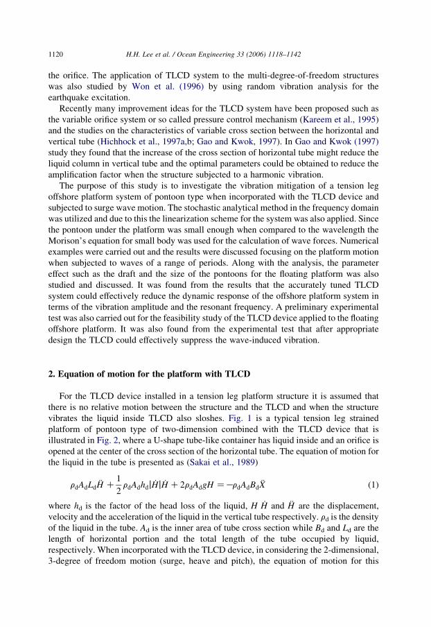
Fig. 13. Comparison of spectral responses of the platform with and without TLCD devices (MZ10 T). (a)
Response in X-direction (surge motion); (b) response in Y-direction (heave motion); (c) response in rotation (pitch
motion).

0.00E+00
5.00E+03
1.00E+04
1.50E+04
2.00E+04
2.50E+04
0 0.1 0.2 0.3 0.4
Frequency (Hz)
Res
pons
e sp
ectr
um (
m2 -
sec) No TLCD
With TLCD
(a)
No TLCD
With TLCD
0.00E+00
5.00E+00
1.00E+01
1.50E+01
2.00E+01
2.50E+01
3.00E+01
3.50E+01
0 0.2 0.4 0.6 0.8 1
Frequency (Hz)
Res
pons
e sp
ectr
um (
m2 -
sec)
(b)
No TLCD
With TLCD
0.00E+00
2.00E-03
4.00E-03
6.00E-03
8.00E-03
1.00E-02
1.20E-02(c)
0 1 2 3 4 5 6 7
Frequency (Hz)
Rot
atio
nal r
espo
nse
spec
trum
Fig. 14. Comparison of spectral responses of the platform with and without TLCD devices (MZ30 T). (a)
Response in X-direction (surge motion); (b) response in Y-direction (heave motion); (c) response in rotation (pitch
motion).
H.H. Lee et al. / Ocean Engineering 33 (2006) 1118–1142 1137
as indicated in (b) of Figs. 10 and 11 the peak of the spectrum seems to be not reduced but
shifted to a lower resonant frequency.
When we examined the mitigation effect by applying the integration over the
spectral density the dissipation of the energy was obtained as shown in Fig. 12. The
mitigation effect on the platform with three different draft of the pontoon from 2 to 4 m
was studied. It is noticed that the mitigation effect is reduced corresponding to the
increase of the pontoon draft from 55 down to about 46%. Corresponding to the
increase of the pontoon draft the TLCD system may have negative influence on
mitigation effect. However the correspondence is not very significant.

Fig. 15. Comparison of the energy dissipation for various platform mass.
H.H. Lee et al. / Ocean Engineering 33 (2006) 1118–11421138
5.3. Mitigation effect with various platform mass
The mass of the platform will influence the vibration frequency and the amplitude. Figs.
13 and 14 show two sets of spectral density of the platform response corresponding to the
wave frequency while the mass is varied from 10 to 30 ton. The mitigation effect is quite
pronounced for both the surge and pitch motion in both cases of 10 and 30 ton as indicated
in (a) and (c) of Figs. 13 and 14. However, the vibration was amplified a bit for the heave
motion and also shifted to a lower resonant frequency as indicated in (b) of both figures.
Fig. 15 shows a comparison of the mitigation effect in terms of the dissipated energy. It
seems that there is not much relevance between the mass variation and the effectiveness of
the TLCD shown in this comparison. This is clear that for the design of the TLCD system
the mass ratio between the TLCD and main structure is the most important factor.
6.42m10.67m
0.7m
Video recorder
Wave damper
Wave maker
Wave meter
Testing model-platform
Fig. 16. Testing set-up for the model-platform equipped with TLCD.
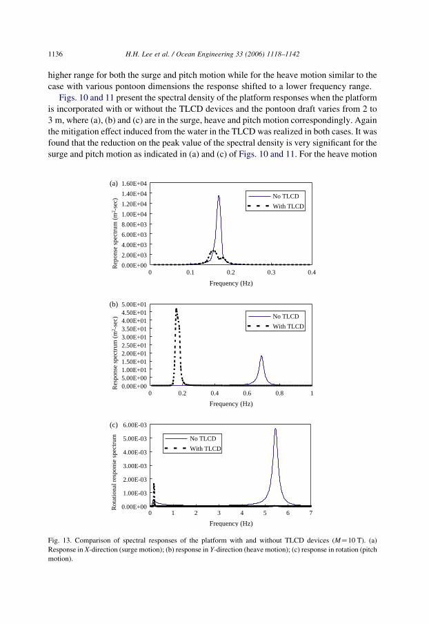
Fig. 17. The model-platform under test in the water tank.
0
20
40
60
80
100
120
140(b)
0 0.2 0.4 0.6 0.8 1
Frequency(Hz)
Res
pons
e Sp
ectr
um(c
m2 -s
ec) No Damper
With TLCD
–12
–7
–2
3
8
0 5 10 15 20Time(sec)
Dis
plac
emen
t(cm
)
(a)
No DamperWith TLCD
Fig. 18. Testing results for the model-platform. (a) Response comparison for the model-platform in the time
domain; (b) response comparison for the model-platform in the frequency domain.
H.H. Lee et al. / Ocean Engineering 33 (2006) 1118–1142 1139

0
20
40
60
80
100
120
140
0 0.2 0.4 0.6 0.8 1
Frequency(Hz)
Res
pons
e Sp
ectr
um(c
m2 -s
ec)
No DamperWith TLCD
Fig. 19. Analytical response comparison for the model-platform in the frequency domain.
H.H. Lee et al. / Ocean Engineering 33 (2006) 1118–11421140
Therefore, once the mass ratio has been determined through the optimum design process
the mitigation effect is not likely to vary significantly.
6. Experimental test and results
An innovational feasibility experimental test was performed for the floating platform
system incorporated with the TLCD devices. For this rather preliminary experiment the
schematic sketch for the test set-up is illustrated in Fig. 16, where a scaled down model of
the platform incorporated with the TLCD device is installed in a water tank. The water
tank is 30 m long, 1 m wide and 1.2 m high. At the left hand-side a hydraulic wave maker
is installed while at the right end of the tank the energy dissipation device is available to
reduce the reflecting waves. The wave meters and video recorders were both employed
and connected to the computers to collect experimental data. The testing model was
constructed with woods as well as the polymer material and a U-shape glass-wise tube was
attached on the top of the platform as a TLCD device in which the water was filled up to
designed level. The dimension of the platform is 0.91 m!0.91 m and the pontoon leg is
0.75 m long by 0.1 m!0.1 m section-area anchored to the bottom of the tank by strained
tethers. The parameters for the model of TLCD are as: LdZ1.20 m; BdZ0.84 m; AdZ2.027!10K3 m2. All of these parameters were through optimal design process for the
best suppression of vibration. The platform-model under test in the water tank is shown
in Fig. 17.
Two sets of test were carried out, one for platform without installation of TLCD device
and the other with TLCD system. The test conditions for the height of the incident waves
and the water depth were set to be constant as 10 and 70 cm while the period of wave was
varied around 1.9 s. Fig. 18(a) showed a typical response comparison for the platform
model in the time domain, where the response of the platform was suppressed obviously
while the TLCD system was installed. The corresponding response spectrum also
indicated a similar suppression effect as shown in Fig. 18(b). However, when compared to
the theoretical prediction as shown in Fig. 19, this mitigation phenomenon is a little less
significant. From this rather preliminary test the result still illustrates qualitatively that

H.H. Lee et al. / Ocean Engineering 33 (2006) 1118–1142 1141
the TLCD system can quite effectively suppress the wave induced vibration for the floating
platform of pontoon type.
7. Conclusions
In this study a typical offshore floating platform of pontoon type incorporated with the
TLCD mitigation system was studied. The mitigation was evaluated corresponding to the
variation of the diameter and the draft of the pontoon and the mass of the platform system.
It was found that as long as the parameters were tuned-up appropriately according to the
properties of main structure the TLCD could have a good performance on vibration
mitigation of a floating platform system.
According to the analytical results the energy dissipated from the TLCD device on the
floating platform system may reach a value higher than 70%, in many cases over 50%. It is
also evident that the variation of the parameter of draft and dimension of the platform
structure will influence the TLCD performance. The amount of the energy being dissipated
is decreased from 73% down to 55% with respect to the increase of the pontoon dimension
in the cases studied. It is also noticed that the mitigation effect is reduced corresponding to
the increase of the pontoon draft from 55% down to about 46%. For the mass variation the
relevance between the mass variation and the effectiveness of the TLCD is not significant.
Furthermore, in the experimental results from a preliminary test for the feasibility of the
TLCD application, this device could be effective on the vibration suppression for the
floating platform.
Therefore, it is concluded that according to this study the application of the TLCD
device to the offshore platform system to ease the wave-induced vibrations is encouraging
in terms of its economy, effectiveness and easiness to apply.
References
Balendra, T., Wang, C.M., Cheong, H.F., 1995. Effectiveness of tuned liquid column dampers for vibration
control of towers. Engineering Structures 17, 668–675.
Borgman, L.E., 1967. Spectral analysis of ocean wave forces on piling. Journal of Waterways and Harbor
Division 93 (WW2), 129–156.
Chaiseri, P., Fujino, Y., Pacheco, B.M., Sun, L.M., 1989. Interaction of tuned liquid damper (TLD) and structure:
theory, experimental verification and application. Structural Engineering and Earthquake Engineering 6, 273–
282.
Chang, C.-C., Hsu, C.T., Swei, S.M., 1998. Control of buildings using single and multiple tuned liquid column
dampers. Earthquake Engineering and Structural Dynamics 23, 388–417.
Chatterjee, P.C., Das, P.K., Faulkner, D., 1997. A hydro-structural analysis program for TLPs. Ocean Engineering
24, 313–333.
Crandal, S.H., Mark, W.D., 1973. Random Vibration in Mechanical Systems. Academic Press, San Diego, CA.
Fujino, Y., Sun, L.M., 1993. Vibration control by multiple tuned liquid dampers (MTLDs). Journal of Structural
Engineering 119, 3482–3502.
Fujino, Y., Pacheco, B.M., Chaiseri, P., Sun, L.M., 1988. Parametric studies on tuned liquid damper (TLD) using
circular containers by free-oscillation experiments. Structural Engineering and Earthquake Engineering 5,
381–391.

H.H. Lee et al. / Ocean Engineering 33 (2006) 1118–11421142
Fujino, Y., Sun, L.M., Pacheco, B.M., 1992. Tuned liquid damper (TLD) for suppressing horizontal motion of
structures. Journal of Engineering Mechanics 118, 2017–2030.
Gao, H., Kwok, K.C.S., 1997. Optimization of tuned liquid column dampers. Engineering Structures 19, 476–
486.
Hitchcock, P.A., Kwok, K.C.S., Watkins, R.D., Samali, B., 1997a. Characteristics of liquid column vibration
absorbers (LCVA)—I. Engineering Structures 19, 126–134.
Hitchcock, P.A., Kwok, K.C.S., Watkins, R.D., Samali, B., 1997b. Characteristics of liquid column vibration
absorbers (LCVA)—II. Engineering Structures 19, 135–144.
Isaacson, M., 1979. Nonlinear forces on bodies. Journal of Waterways and Harbors Division ASCE WW3, 213–
227.
Jain, A.K., 1997. Nonlinear coupled response of offshore tension leg platforms to regular wave forces. Ocean
Engineering 24 (7), 577–592.
Kareem, A., Kline, S., 1995. Performance of multiple mass dampers under random loadings. Journal of Structural
Control 3–5, FP5-19–FP5-28.
Lee, H.H., Wang, P.-W., 2000. Analytical solution on the surge motion of tension leg twin-platform structural
system. Ocean Engineering 27, 393–415.
Lee, H.H., Wang, W.-S., Wang, P.-W., 1999a. Dynamic motion of tension leg platform with wave–large body and
wave–small body interactions. International Offshore and Polar Engineering Conference 1, 309–314.
Lee, H.H., Wang, P.-W., Lee, C.P., 1999b. Dragged surge motion of tension leg platforms and strained elastic
tether. Ocean Engineering 26, 575–594.
Mei, C.C., 1978. Numerical methods in water wave diffraction and radiation. Annual Review of Fluid Mechanics
10, 393–416.
Newman, J.N., 1977. Marine Hydrodynamics. MIT Press, Cambridge, MA.
Pierson, W.J., Moskowitz, L., 1964. A proposed spectral form for fully developed wind seas based on the
similarity theory of S.A. Kitaigorodskii. Journal of Geophysical Research 69, 5181–5190.
Sakai F., Takaeda S., Tamaki T. 1989. Tuned liquid column damper—new type device for suppression of
building vibration, Proceedings of International Conference on High-rise Buildings, pp. 926-931.
Sarpkaya, T., Isaacson, M., 1981. Mechanics of Wave Forces on Offshore Structures. Van Nostrand Reinhold,
New York.
Sun, K., Cheong, H.F., Balendra, T., 1993. Effect of liquid dampers on along-wind response of structures.
Proceedings of the Asia-Pacific Vibration Conference ’93, Kitakyushu, Nov. 1993, Symposium on FIVES,
pp. 835–840.
Wen, Y.K., 1980. Equivalent linearization for hysteretic systems under random excitation. Journal of Applied
Mechanics 47, 150–154.
Won, A.Y.J., Piers, J.A., Haroun, M.A., 1996. Stochastic seismic performance evaluation of tuned liquid column
dampers. Earthquake Engineering and Structural Dynamics 25, 1259–1274.
Xu, Y.L., Samali, B., Kwok, K.C.S., 1992. Control of along-wind response of structures by mass and liquid
dampers. Journal of Engineering Mechanics 118, 20–39.
Yamamoto, T., Yoshida, A., Ijima, T., 1982. Dynamics of elastically moored floating objects. In: Kirk, C.L. (Ed.),
Dynamics Analysis of Offshore Structures. CML, Southampton.


![Vibration suppression of cables using tuned inerter dampers · tuned viscous mass dampers [28,29], tuned mass-damper-inerter systems [30] and tuned inerter dampers (TID) [31]. Unlike](https://img.dokumen.tips/doc/110x75/5ebe7d97c8153850be39552a/vibration-suppression-of-cables-using-tuned-inerter-dampers-tuned-viscous-mass-dampers.jpg)