Embed Size (px)
Citation preview
Resource Management GuideUpdate 2 and later for
ESX Server 3.5, ESX Server 3i version 3.5, VirtualCenter 2.5

VMware, Inc.3401 Hillview Ave.Palo Alto, CA 94304www.vmware.com
2 VMware, Inc.
Resource Management Guide
You can find the most up-to-date technical documentation on the VMware Web site at:
http://www.vmware.com/support/
The VMware Web site also provides the latest product updates.
If you have comments about this documentation, submit your feedback to:
© 2006–2009 VMware, Inc. All rights reserved. This product is protected by U.S. and international copyright and intellectual property laws. VMware products are covered by one or more patents listed at http://www.vmware.com/go/patents.
VMware, the VMware “boxes” logo and design, Virtual SMP, and VMotion are registered trademarks or trademarks of VMware, Inc. in the United States and/or other jurisdictions. All other marks and names mentioned herein may be trademarks of their respective companies.
Resource Management GuideRevision: 20090612Item: EN-0000-33-04

VMware, Inc. 3
Contents
About This Book 9
1 Getting Started with Resource Management 13Viewing Host Resource Information 14
Understanding Virtual Machine Resource Allocation 18
Reserving Host Resources 20
Virtual Machine Attributes: Shares, Reservation, and Limit 20
Admission Control 22
Changing Virtual Machine Attributes 23
Creating and Customizing Resource Pools 25
Understanding Expandable Reservation 29
Creating and Customizing Clusters 30
2 Resource Management Concepts 33What Are Resources? 33
Resource Providers and Consumers 33
How ESX Server Manages Resources 35
How Administrators Configure Resources 35
Resource Utilization and Performance 36
Understanding ESX Server Architecture 36
VMkernel 37
VMkernel Resource Manager 37
VMkernel Hardware Interface Layer 37
Virtual Machine Monitor 37
Service Console 38
How Administrators Affect CPU Management 38
How Administrators Can Affect Memory Management 39
Understanding CPU and Memory Virtualization 39
CPU Virtualization Basics 39
Memory Virtualization Basics 40

Resource Management Guide
4 VMware, Inc.
3 Understanding and Managing Resource Pools 43What Are Resource Pools? 44
Why Use Resource Pools? 45
Host Resource Pools and Cluster Resource Pools 46
Resource Pool Admission Control 47
Creating Resource Pools 48
Understanding Expandable Reservations 50
Viewing Resource Pool Information 50
Resource Pool Summary Tab 51
Resource Pool Resource Allocation Tab 52
Changing Resource Pool Attributes 54
Monitoring Resource Pool Performance 54
Adding Virtual Machines to Resource Pools 55
Removing Virtual Machines from Resource Pools 56
Resource Pools and Clusters 56
Clusters Enabled for DRS 57
Clusters Not Enabled for DRS 58
4 Understanding Clusters 59Introduction to Clusters 59
VMware DRS 60
VMware HA 60
Clusters and VirtualCenter Failure 61
Understanding VMware DRS 62
Initial Placement 62
Load Balancing and Virtual Machine Migration 66
Distributed Power Management 68
DRS Clusters, Resource Pools, and ESX Server 70
Host Maintenance and Standby Modes 71
Understanding VMware HA 72
Traditional and HA Failover Solutions 73
VMware HA Features 74
Failover Capacity 75
Planning for HA Clusters 75
VMware HA and Special Situations 77
Primary and Secondary Hosts 78
HA Clusters and Maintenance Mode 78
HA Clusters and Disconnected Hosts 78
HA Clusters and Host Network Isolation 79

VMware, Inc. 5
Contents
Using HA and DRS Together 80
Valid, Yellow, and Red Clusters 81
Valid Cluster 81
Yellow Cluster 84
Red Cluster 85
5 Creating a VMware Cluster 89Cluster Prerequisites 89
Clusters Enabled for HA 90
VirtualCenter VMotion Requirements 91
Cluster Creation Overview 93
Creating a Cluster 94
Choosing Cluster Features 94
Selecting Automation Level 94
Selecting HA Options 95
Selecting a Virtual Machine Swapfile Location 96
Finishing Cluster Creation 96
Viewing Cluster Information 97
Summary Page 97
DRS Resource Distribution Charts 99
DRS Recommendations Page 100
6 Managing VMware DRS 103Customizing DRS 103
Adding Hosts to a DRS Cluster 104
Adding Managed Hosts to a Cluster 104
Adding Unmanaged Hosts to a Cluster 105
Removing Hosts from Clusters 106
Host Removal and Resource Pool Hierarchies 106
Host Removal and Virtual Machines 107
Host Removal and Invalid Clusters 107
Applying DRS Recommendations 107
Recommendation Grouping 108
Using the DRS Recommendations Page 109
Reconfiguring DRS 109
Using DRS Affinity Rules 110
Understanding Rule Results 112
Disabling or Deleting Rules 112

Resource Management Guide
6 VMware, Inc.
7 Clusters and Virtual Machines 113Adding Virtual Machines to a Cluster 113
Adding a Virtual Machine During Creation 113
Migrating a Virtual Machine to a Cluster 114
Adding a Host with Virtual Machines to a Cluster 114
Powering On Virtual Machines in a Cluster 114
DRS Enabled 114
HA Enabled 115
Removing Virtual Machines from a Cluster 115
Migrating Virtual Machines out of a Cluster 115
Removing a Host with Virtual Machines from a Cluster 116
Customizing DRS for Virtual Machines 116
Customizing HA for Virtual Machines 117
Monitoring Virtual Machines 119
8 Managing VMware HA 121Customizing HA 121
Adding Hosts to an HA Cluster 122
Adding Managed Hosts to a Cluster 122
Adding Unmanaged Hosts to a Cluster 122
Adding Hosts with Incompatible Networking Configuration 123
Results of Adding Hosts to a Cluster 124
Configuring and Unconfiguring HA on a Host 124
Working with VMware HA 125
Setting Advanced HA Options 126
9 Advanced Resource Management 129CPU Virtualization 130
Software CPU Virtualization 130
Hardware‐Assisted CPU Virtualization 130
Virtualization and Processor‐Specific Behavior 131
Performance Implications 131
Using CPU Affinity to Assign Virtual Machines to Specific Processors 132
Multicore Processors 134
Hyperthreading 135
Enabling Hyperthreading 136
Hyperthreading and ESX Server 136
Advanced Server Configuration for Hyperthreading 137
Quarantining 139
Hyperthreading and CPU Affinity 139
VMware, Inc. 7
Contents
Memory Virtualization 139
Software Memory Virtualization 139
Hardware‐Assisted Memory Virtualization 140
Performance Implications 141
Understanding Memory Overhead 142
Memory Allocation and Idle Memory Tax 144
How ESX Server Hosts Allocate Memory 144
How Host Memory Is Used 145
Memory Tax for Idle Virtual Machines 146
How ESX Server Hosts Reclaim Memory 146
Memory Balloon (vmmemctl) Driver 147
Swap Space and Guest Operating Systems 148
Swapping 148
Swap Space and Memory Overcommitment 150
Swap Files and ESX Server Failure 150
Sharing Memory Across Virtual Machines 150
Advanced Attributes and What They Do 151
Setting Advanced Host Attributes 151
Setting Advanced Virtual Machine Attributes 155
10 Using NUMA Systems with ESX Server 157Introduction to NUMA 158
What Is NUMA? 158
NUMA Challenges for Operating Systems 158
ESX Server NUMA Scheduling 159
VMware NUMA Optimization Algorithms 160
Home Nodes and Initial Placement 160
Dynamic Load Balancing and Page Migration 161
Transparent Page Sharing Optimized for NUMA 162
Manual NUMA Controls 162
IBM Enterprise X‐Architecture Overview 163
AMD Opteron‐Based Systems Overview 164
Obtaining NUMA Configuration Information and Statistics 165
CPU Affinity for Associating Virtual Machines with a Single NUMA Node 165
Memory Affinity for Associating Memory Allocations with a NUMA Node 166

Resource Management Guide
8 VMware, Inc.
11 Best Practices 169Resource Management Best Practices 169
Creating and Deploying Virtual Machines 170
Planning 170
Creating Virtual Machines 170
Deploying the Guest Operating System 171
Deploying Guest Applications 171
Configuring VMkernel Memory 171
VMware HA Best Practices 172
Networking Best Practices 172
Setting Up Networking Redundancy 173
Other VMware HA Cluster Considerations 176
Appendix: Performance Monitoring Utilities: resxtop and esxtop 177Deciding to Use resxtop or esxtop 177
Using the resxtop Utility 177
Using the esxtop Utility 178
Using the Utilities in Interactive Mode 179
Interactive Mode Command‐Line Options 179
CPU Panel 182
Memory Panel 185
Storage Panels 190
Network Panel 199
Using the Utilities in Batch Mode 200
Using the Utilities in Replay Mode 201
Index 203

VMware, Inc. 9
This manual, the Resource Management Guide, discusses resource management for
VMware® Virtual Infrastructure environments. Its focus is on the following major
topics:
Resource allocation and resource management concepts
Virtual machine attributes and admission control
Resource pools and how to manage them
Clusters, VMware Distributed Resource Scheduler (DRS),
VMware High Availability (HA), and how to work with them
Advanced resource management options
Performance considerations
Resource Management Guide covers both ESX Server 3.5 and ESX Server 3i version 3.5.
For ease of discussion, this book uses the following product naming conventions:
For topics specific to ESX Server 3.5, this book uses the term “ESX Server 3.”
For topics specific to ESX Server 3i version 3.5, this book uses the term
“ESX Server 3i.”
For topics common to both products, this book uses the term “ESX Server.”
When the identification of a specific release is important to a discussion, this book
refers to the product by its full, versioned name.
When a discussion applies to all versions of ESX Server for
VMware Infrastructure 3, this book uses the term “ESX Server 3.x.”
About This Book

Resource Management Guide
10 VMware, Inc.
Intended AudienceThis manual is for system administrators who want to understand how the system
manages resources and how they can customize the default behavior. It’s also essential
for anyone who wants to understand and use resource pools, clusters, DRS, or HA.
This manual assumes you have a working knowledge of ESX Server and of the
VirtualCenter Server.
Document FeedbackVMware welcomes your suggestions for improving our documentation. If you have
comments, send your feedback to:
VMware Infrastructure Documentation The VMware Infrastructure documentation consists of the combined VMware
VirtualCenter and ESX Server documentation set.
Abbreviations Used in FiguresThe figures in this book use the abbreviations listed in Table 1.
Table 1. Abbreviations
Abbreviation Description
database VirtualCenter database
datastore Storage for the managed host
dsk# Storage disk for the managed host
hostn VirtualCenter managed hosts
RP Resource pool
SAN Storage area network type datastore shared between managed hosts
tmplt Template
user# User with access permissions
VC VirtualCenter
VI VMware Infrastructure Client
VM# Virtual machines on a managed host

VMware, Inc. 11
About This Book
Technical Support and Education ResourcesThe following sections describe the technical support resources available to you. To
access the current versions of this book and other books, go to:
http://www.vmware.com/support/pubs.
Online and Telephone Support
Use online support to submit technical support requests, view your product and
contract information, and register your products. Go to:
http://www.vmware.com/support
Customers with appropriate support contracts should use telephone support for the
fastest response on priority 1 issues. Go to:
http://www.vmware.com/support/phone_support.html
Support Offerings
Find out how VMware support offerings can help meet your business needs. Go to:
http://www.vmware.com/support/services
VMware Professional Services
VMware Education Services courses offer extensive hands‐on labs, case study
examples, and course materials designed to be used as on‐the‐job reference tools.
Courses are available onsite, in the classroom, and live online. For onsite pilot
programs and implementation best practices, VMware Consulting Services provides
offerings to help you assess, plan, build, and manage your virtual environment. To
access information about education classes, certification programs, and consulting
services, go to http://www.vmware.com/services.

Resource Management Guide
12 VMware, Inc.

VMware, Inc. 13
1
This chapter introduces basic resource management concepts using a simple example.
The chapter steps you through resource allocation, first in a single‐host environment,
and then in a more complex multihost environment.
This chapter discusses the following topics:
“Viewing Host Resource Information” on page 14
“Understanding Virtual Machine Resource Allocation” on page 18
“Changing Virtual Machine Attributes” on page 23
“Creating and Customizing Resource Pools” on page 25
“Understanding Expandable Reservation” on page 29
“Creating and Customizing Clusters” on page 30
Getting Started with Resource Management 1

Resource Management Guide
14 VMware, Inc.
Viewing Host Resource InformationIn this section, you explore a host’s resources and learn how to determine who uses
them.
Assume that a system administrator for a small company has set up two virtual
machines, VM‐QA and VM‐Marketing, on an ESX Server host. See Figure 1‐1.
Figure 1-1. Single Host with Two Virtual Machines
To view information about a host
1 Start a VMware Infrastructure Client (VI Client) and connect to a VirtualCenter
Server.
2 In the inventory panel on the left, select the host.
With the Summary tab selected, the panels display the following information
about the host.
NOTE You can also perform many of the tasks in this chapter using a VI Client
connected to an ESX Server system or a VI Web Access Client connected to a server.
Summary Panel Information Shown
General panel Shows information about processors, processor type, and so on.
Commands panel Allows you to select commands to execute for the selected host.
Resources panel Shows information about the total resources of the selected host. This panel includes information about the datastores connected to the host.
VM-QA
ESX Serverhost
VM-Marketing

VMware, Inc. 15
Chapter 1 Getting Started with Resource Management
3 For detailed information about available memory, click the Configuration tab, and
select Memory.
The panel lists total resources, how much is used by virtual machines, and how
much is used by the service console (ESX Server 3 only).

Resource Management Guide
16 VMware, Inc.
The amount of physical memory the virtual machines can use is always less than
what is in the physical host because the virtualization layer takes up some
resources. For example, a host with a dual 3.2GHz CPU and 2GB of memory might
make 6GHz of CPU power and 1.5GB of memory available for use by virtual
machines.
4 For detailed information about how the two virtual machines use the host’s
resources, click the Resource Allocation tab.
You see the CPU Reservation and Memory Reservation, how much of the
reservation is used, and how much is available.
The fields display the following information.
NOTE In the Resource Allocation tab shown, no virtual machines are running, so
no CPU or memory is used. You revisit this tab after powering on a virtual
machine.
Field Description
CPU Reservation Total CPU resources available for this host.
CPU Reservation Used Total CPU resources of this host that are reserved by running virtual machines.
Note: Virtual machines that are not powered on do not consume CPU resources. For powered‐on virtual machines, the system reserves CPU resources according to each virtual machine’s Reservation setting.
CPU Reservation Unused Total CPU resources of this host that are not currently reserved.
Consider a virtual machine with reservation=2GHz that is totally idle. It has 2GHz reserved, but it is not using any of its reservation.
Other virtual machines cannot reserve these 2GHz.
Other virtual machines can use these 2GHz, that is, idle CPU reservations are not wasted.

VMware, Inc. 17
Chapter 1 Getting Started with Resource Management
5 Click the Memory or CPU button depending on the information you want.
Memory Reservation Total memory resources available for this host.
If a virtual machine has a memory reservation but has not yet accessed its full reservation, the unused memory can be reallocated to other virtual machines.
Memory Reservation Used
Total memory resources of this host that are reserved by a running virtual machine and virtualization overhead.
Note: Virtual machines that are not powered on do not consume memory resources. For powered‐on virtual machines, the system reserves memory resources according to each virtual machine’s Reservation setting and overhead.
After a virtual machine has accessed its full reservation, ESX Server allows the virtual machine to retain this much memory, and will not reclaim it, even if the virtual machine becomes idle and stops accessing memory.
Memory Reservation Unused
Total memory resources of this host that are not currently reserved.
Field Description

Resource Management Guide
18 VMware, Inc.
Understanding Virtual Machine Resource AllocationWhen you create a virtual machine, the New Virtual Machine wizard prompts you for
the memory size for this virtual machine. This amount of memory is the same as the
amount of memory you install in a physical machine.
Field Description
Name Name of the virtual machine.
Reservation — MHz/MB
Amount of CPU or memory reserved for this virtual machine.
By default, no reservation is specified and 0 is displayed. See “Reservation” on page 21.
Limit Amount of CPU or memory specified as the upper limit for this virtual machine.
By default, no limit is specified and Unlimited is displayed. See “Limit” on page 22.
Shares Shares specified for this virtual machine. Each virtual machine is entitled to resources in proportion to its specified shares, bounded by its reservation and limit. A virtual machine with twice as many shares as another is entitled to twice as many resources.
Shares default to Normal. See “Shares” on page 20.
Shares Value Number of shares allocated to this virtual machine.
% Shares Percentage of shares allocated to this virtual machine.
Type For resource pools, either Expandable or Fixed. See “Understanding Expandable Reservation” on page 29.
NOTE The ESX Server host makes this memory available to virtual machines. The host
allocates the number of megabytes specified by the reservation directly to the virtual
machine. Anything beyond the reservation is allocated using the hostʹs physical
resources or, when physical resources are not available, handled using special
techniques such as ballooning or swapping. See “How ESX Server Hosts Reclaim
Memory” on page 146.

VMware, Inc. 19
Chapter 1 Getting Started with Resource Management
Figure 1-2. Virtual Machine Memory Configuration
The system also prompts for the number of virtual processors (CPUs) if the operating
system you have chosen supports more than one.
Figure 1-3. Virtual CPU Configuration
When CPU resources are overcommitted, the ESX Server host time‐slices the physical
processors across all virtual machines so each virtual machine runs as if it has the
specified number of processors.
When an ESX Server host runs multiple virtual machines, it allocates each virtual
machine a share of the physical resources. With the default resource allocation settings,
all virtual machines associated with the same host receive:
An equal share of CPU per virtual CPU. That means single‐processor virtual
machines are assigned only half of the resources of a dual‐processor virtual
machine.
An equal share per MB of virtual memory size. That means an 8GB virtual machine
is entitled to eight times as much memory as a 1GB virtual machine.

Resource Management Guide
20 VMware, Inc.
Reserving Host Resources
In some situations, system administrators want to know that a certain amount of
memory for a virtual machine comes directly from the physical resources of the
ESX Server machine. Similarly, the administrator might want to guarantee that a certain
virtual machine always receives a higher percentage of the physical resources than
other virtual machines.
You can reserve physical resources of the host using each virtual machine’s attributes,
discussed in the next section.
Virtual Machine Attributes: Shares, Reservation, and Limit
For each virtual machine, you can specify shares, reservation (minimum), and limit
(maximum). This section explains what it means to specify these attributes.
Shares
Shares specify the relative priority or importance of a virtual machine. If a virtual
machine has twice as many shares of a resource as another virtual machine, it is entitled
to consume twice as much of that resource. Shares are typically specified as High,
Normal, or Low and these values specify share values with a 4:2:1 ratio, respectively.
You can also choose Custom to assign a specific number of shares (which expresses a
proportional weight) to each virtual machine.
Specifying shares makes sense only with regard to sibling virtual machines or resource
pools, that is, virtual machines or resource pools with the same parent in the resource
pool hierarchy. Siblings share resources according to their relative share values,
bounded by the reservation and limit. See “What Are Resource Pools?” on page 44 for
an explanation of the hierarchy and sibling concepts.
When you assign shares to a virtual machine, you always specify the relative priority
for that virtual machine.
NOTE In most cases, use the default settings. See Chapter 11, “Best Practices,” on
page 169 for information on how to best use custom resource allocations.

VMware, Inc. 21
Chapter 1 Getting Started with Resource Management
CPU and memory share values, respectively, default to:
High — 2000 shares per virtual CPU and 20 shares per megabyte of virtual
machine memory
Normal — 1000 shares per virtual CPU and 10 shares per megabyte of virtual
machine memory
Low — 500 shares per virtual CPU and 5 shares per megabyte of virtual machine
memory
You can also specify a Custom share value.
For example, an SMP virtual machine with two virtual CPUs and 1GB RAM with CPU
and memory shares set to Normal has 2x1000=2000 shares of CPU and 10x1024=10240
shares of memory.
The amount of resources represented by each share changes when a new virtual
machine is powered on. This affects all virtual machines in the same resource pool. For
example:
Two virtual machines run on a host with 8GHz. Their CPU shares are set to
Normal and get 4GHz each.
A third virtual machine is powered on. Its CPU shares value is set to High, which
means it should have twice as many shares as the machines set to Normal. The new
virtual machine receives 4GHz and the two other machines get only 2GHz each.
Note that the same result occurs if the user specifies a custom share value of 2000
for the third virtual machine.
Reservation
Reservation specifies the guaranteed reservation for a virtual machine. The server
allows you to power on a virtual machine only if the CPU and memory reservation is
available. The server guarantees that amount even when the physical server is heavily
loaded. The reservation is expressed in concrete units (megahertz or megabytes). When
resources are not used, the ESX Server host makes them available to other virtual
machines.
NOTE Virtual machines with more than one virtual CPU are called SMP (symmetric
multiprocessing) virtual machines.

Resource Management Guide
22 VMware, Inc.
For example, assume you have 2GHz available and specify a reservation of 1GHz for
VM1 and 1GHz for VM2. Now each virtual machine is guaranteed to get 1GHz if it
needs it. However, if VM1 is using only 500MHz, VM2 can use 1.5GHz.
Reservation defaults to 0. It is a good idea to specify a reservation to guarantee that the
necessary CPU or memory are always available for the virtual machine.
Limit
Limit specifies the upper limit for CPU or memory for a virtual machine. A server can
allocate more than the reservation to a virtual machine, but never allocates more than
the limit, even if there is unutilized CPU or memory on the system. The limit is
expressed in concrete units (megahertz or megabytes).
CPU and memory limit default to unlimited. When the memory limit is unlimited, the
amount of memory configured for the virtual machine when it was created becomes its
implicit limit in most cases.
In most cases, it is not necessary to specify a limit. There are benefits and drawbacks:
Benefits — Assigning a limit is useful if you start with a small number of virtual
machines and want to manage user expectations. Performance will deteriorate as
you add more virtual machines. You can simulate having fewer resources available
by specifying a limit.
Drawbacks — You might waste idle resources if you specify a limit. The system
does not allow virtual machines to use more resources than the limit, even when
the system is underutilized and idle resources are available. Specify the limit only
if you have good reasons for doing so.
Admission Control
When you power on a virtual machine, the system checks the amount of CPU and
memory resources that have not yet been reserved. Based on the available unreserved
resources, the system determines whether it can guarantee the reservation for which
the virtual machine has been configured (if any). This process is called admission control.
If enough unreserved CPU and memory are available, or if there is no reservation, the
virtual machine is powered on. Otherwise, an Insufficient Resources warning
appears.
NOTE In addition to the user‐specified memory reservation, for each virtual machine
there is also an amount of overhead memory. This extra memory commitment is
included in the admission control calculation. See “Understanding Memory Overhead”
on page 142.

VMware, Inc. 23
Chapter 1 Getting Started with Resource Management
When the experimental Distributed Power Management feature is enabled, hosts may
be placed in standby mode (that is, powered off) to reduce power consumption. The
unreserved resources provided by these hosts are considered available for the purpose
of admission control. If a virtual machine cannot be powered on without these
resources, a recommendation to power on sufficient standby hosts is made. See
“Distributed Power Management” on page 68.
Changing Virtual Machine AttributesEarlier in this chapter, you viewed hosts and virtual machines and their resource
allocation. You did not specify shares, reservation, and limit for the virtual machines.
In this example, assume:
The QA virtual machine is memory intensive. You want to specify that, when
system memory is overcommitted, VM‐QA can use twice as much memory and
CPU as the Marketing virtual machine. Set memory shares and CPU shares to
High.
Make sure that the Marketing virtual machine has a certain amount of guaranteed
CPU resources. You can do so using a Reservation setting.
To edit a virtual machine’s resource allocation
1 Start a VI Client and connect to a VirtualCenter Server.
2 Select the host in the inventory panel and click the Resource Allocation tab.
3 Right‐click VM‐QA, the virtual machine for which you want to change shares, and
choose Edit Resource Settings.
4 In the CPU Resources panel, choose High from the Shares drop‐down menu.

Resource Management Guide
24 VMware, Inc.
5 Repeat these steps in the Memory Resources panel, and click OK.
6 Right‐click the marketing virtual machine (VM‐Marketing).
7 Change the value in the Reservation field to the number, and click OK.
8 Click OK when you’re done.

VMware, Inc. 25
Chapter 1 Getting Started with Resource Management
9 Select the host’s Resource Allocation tab and click CPU, you see that shares for
VM‐QA are twice that of the other virtual machine.
Because the virtual machines have not been powered on, the Reservation Used
fields have not changed.
10 Power on VM‐Marketing and see how the CPU Reservation Used and CPU
Unreserved fields change.
Creating and Customizing Resource PoolsAs organizations grow, they can afford faster and better systems and allocate more
resources to the different departments. In this section, you learn how to use resource
pools to divide a host’s resources. You can also use resource pools in conjunction with
VMware clusters, where they allow you to manage the resources of all hosts in a cluster
as one pool of resources.
When you create a resource pool, specify the following attributes:
Reservation, limit, and shares behave just as they do for virtual machines. See
“Changing Virtual Machine Attributes” on page 23.
The Reservation Type attribute allows you to set up the resource pool so that the
pool can reserve available resources from its parent if it does not have enough
resources available locally. See “Understanding Expandable Reservation” on
page 29.

Resource Management Guide
26 VMware, Inc.
Continuing with the example above, assume that you no longer want to assign one
virtual machine each to your QA and Marketing departments but want to give each
department a predefined amount of resources. Depending on departmental needs, the
department administrator can create virtual machines for the department.
For example, if you started with a host that provides 6GHz of CPU and 3GB of memory,
you can choose share allocations of High for RP‐QA and shares allocations of Normal
for RP‐Marketing. That results in approximately 4GHz and 2GB of memory for RP‐QA,
and 2GHz and 1GB for RP‐Marketing. Those resources are then available to the virtual
machines in the respective resource pools. See Figure 1‐4.
Figure 1-4. ESX Server Host with Two Resource Pools
To create and customize resource pools
1 Start a VI Client and connect to a VirtualCenter Server.
2 In the inventory panel on the left, select a host and choose New Resource Pool in
the Commands panel on the right.
3 In the Create Resource Pool dialog box, type the resource pool name (for example,
RP‐QA).
VM-QA 1 VM-QA 2
6GHz, 3GB
4GHz, 2GB 2GHz, 1GBRP-QA
VM-Marketing 1 VM-Marketing 2 VM-Marketing 3
RP-Marketing
ESX Serverhost

VMware, Inc. 27
Chapter 1 Getting Started with Resource Management
4 Specify Shares of High for the CPU and memory resources of RP‐QA.
5 Create a second resource pool, RP‐Marketing:
a Leave Shares at Normal for CPU and memory.
b Specify a Reservation for CPU and memory.
c Click OK to exit.
6 Select the host in the inventory panel and click the Resource Allocation tab.
The resource pools have been added to the display. In the top panel, the
Reservation for the second resource pool has been subtracted from the unreserved
resources. In the second panel, resource pool information, including the resource
pool type, is now available.
Resource Management Guide
28 VMware, Inc.
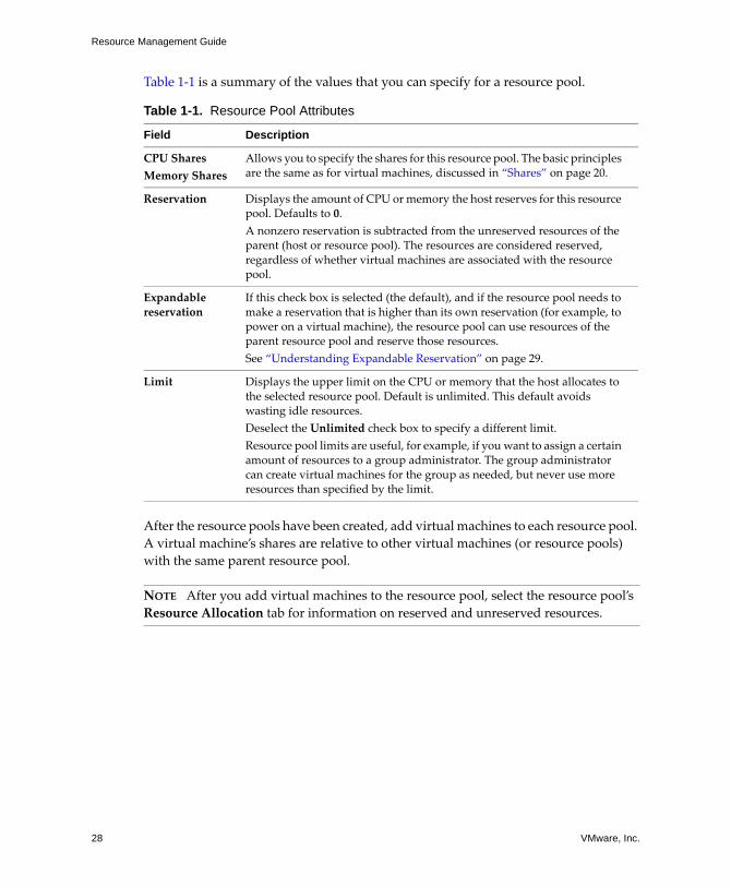
Table 1‐1 is a summary of the values that you can specify for a resource pool.
After the resource pools have been created, add virtual machines to each resource pool.
A virtual machine’s shares are relative to other virtual machines (or resource pools)
with the same parent resource pool.
Table 1-1. Resource Pool Attributes
Field Description
CPU Shares
Memory Shares
Allows you to specify the shares for this resource pool. The basic principles are the same as for virtual machines, discussed in “Shares” on page 20.
Reservation Displays the amount of CPU or memory the host reserves for this resource pool. Defaults to 0.
A nonzero reservation is subtracted from the unreserved resources of the parent (host or resource pool). The resources are considered reserved, regardless of whether virtual machines are associated with the resource pool.
Expandable reservation
If this check box is selected (the default), and if the resource pool needs to make a reservation that is higher than its own reservation (for example, to power on a virtual machine), the resource pool can use resources of the parent resource pool and reserve those resources.
See “Understanding Expandable Reservation” on page 29.
Limit Displays the upper limit on the CPU or memory that the host allocates to the selected resource pool. Default is unlimited. This default avoids wasting idle resources.
Deselect the Unlimited check box to specify a different limit.
Resource pool limits are useful, for example, if you want to assign a certain amount of resources to a group administrator. The group administrator can create virtual machines for the group as needed, but never use more resources than specified by the limit.
NOTE After you add virtual machines to the resource pool, select the resource pool’s
Resource Allocation tab for information on reserved and unreserved resources.

VMware, Inc. 29
Chapter 1 Getting Started with Resource Management
Understanding Expandable ReservationHow expandable reservations work is easiest to understand using an example.
Assume the following scenario (shown in Figure 1‐5):
1 Parent pool RP‐MOM has a reservation of 6GHz and one running virtual machine
VM‐M1 that reserves 1GHz.
2 You create a child resource pool RP‐KID with a reservation of 2GHz and with
Expandable Reservation selected.
3 You add two virtual machines, VM‐K1 and VM‐K2, with reservations of 2GHz
each to the child resource pool and attempt to power them on.
4 VM‐K1 can reserve the resources directly from RP‐KID (which has 2GHz).
5 No local resources are available for VM‐K2, so it borrows resources from the parent
resource pool, RP‐MOM. RP‐MOM has 6GHz minus 1GHz (reserved by the virtual
machine) minus 2GHz (reserved by RP‐KID), which leaves 3GHz unreserved.
With 3GHz available, you can power on the 2GHz virtual machine.
Figure 1-5. Admission Control with Expandable Resource Pools, Example 1
VM-K1, 2GHz VM-K2, 2GHz
2GHz
6GHz
RP-KID
VM-M1, 1GHz
RP-MOM

Resource Management Guide
30 VMware, Inc.
Now, consider another scenario with VM‐M1 and VM‐M2 (shown in Figure 1‐6):
1 Power on two virtual machines in RP‐MOM with a total reservation of 3GHz.
2 You can still power on VM‐K1 in RP‐KID because 2GHz are available locally.
3 When you try to power on VM‐K2, RP‐KID has no unreserved CPU capacity so it
checks its parent. RP‐MOM has only 1GHz of unreserved capacity available (5GHz
of RP‐MOM are already in use—3GHz reserved by the local virtual machines and
2GHz reserved by RP‐KID). As a result, you cannot power on VM‐K2, which
requires a 2GHz reservation.
Figure 1-6. Admission Control with Expandable Resource Pools, Example 2
Creating and Customizing ClustersIn the previous section, you set up two resource pools that shared the resources of a
single host. A cluster consists of a set of hosts. If VMware DRS (Distributed Resource
Scheduling) is enabled, the cluster supports shared resource pools and performs
placement and dynamic load balancing for virtual machines in the cluster. The
experimental Distributed Power Management feature can also be enabled with DRS. It
reduces a cluster’s power consumption by providing recommendations for placing
hosts into standby power mode when sufficient excess capacity exists. If VMware HA
(High Availability) is enabled, the cluster supports failover. When a host fails, all
associated virtual machines are restarted on different hosts.
This section steps you through creating a cluster and explains basic cluster
functionality. The focus is on the default behavior of basic clusters.
VM-K1, 2GHz VM-K2, 2GHz
2GHz
6GHz
RP-KID
VM-M1, 1GHz VM-M2, 2GHz
RP-MOM
NOTE You must be licensed to use cluster features.

VMware, Inc. 31
Chapter 1 Getting Started with Resource Management
Assume you have a cluster that consists of three physical hosts. Each host provides
3GHz and 1.5GB, with a total of 9GHz and 4.5GB available. If you enable the cluster for
DRS, you can create resource pools with different reservation or shares to control
aggregate allocations for groups of virtual machines, for example, by department,
project, or user.
For DRS‐enabled clusters, the system places virtual machines on the most suitable
physical hosts (or makes recommendations for placement) when virtual machines are
powered on. The exact behavior depends on the default automation level of the cluster
or the automation mode of specific virtual machines.
To create and customize a cluster
1 Start a VI Client and connect to a VirtualCenter Server.
2 In the inventory panel on the left, right‐click a datacenter and choose New Cluster.
3 Name the cluster and enable it for HA and DRS.
4 Keep the default, fully automated, for DRS.
5 Keep the defaults for host failures and admission control for HA.
6 Select the appropriate option for Swapfile Policy for Virtual Machines.
7 Click Finish.
The VirtualCenter Server creates a new cluster with the specified attributes.
For information on DRS, HA, and available attributes, see Chapter 5, “Creating a
VMware Cluster,” on page 89.
The next task is to add a number of hosts to the cluster. Using clusters enabled for DRS
makes sense even if you have only two hosts in the cluster.
A cluster enabled for HA can support a maximum of four concurrent host failures. In
the following steps, you add a host to the cluster that is managed by the same
VirtualCenter Server.

Resource Management Guide
32 VMware, Inc.
To add a host to the cluster
1 In the left panel of the VI Client, select the host and drag it over the cluster’s icon.
If the cluster is enabled for DRS, you are prompted whether you want to add the
host’s virtual machines directly to the cluster’s (invisible) root resource pool or
whether you want to create a new resource pool to represent that host. The root
resource pool is at the top level and is not displayed because the resources are
owned by the cluster.
If the cluster is not enabled for DRS, all resource pools are removed.
2 Choose the appropriate option.
If you choose the first option, the resource pool hierarchy that was on the host you
are adding to the cluster is collapsed and all resources will be managed by the
cluster. Choose the second option if you created resource pools for the host.
3 Select the cluster and choose its Resource Allocation tab to add more hosts and
look at the resource allocation information for the cluster.
NOTE If you are using a cluster enabled for HA, that cluster might be marked with
a red warning icon until you have added enough hosts to satisfy the specified
failover capacity. See “Valid, Yellow, and Red Clusters” on page 81.

VMware, Inc. 33
2
This chapter discusses the following topics:
“What Are Resources?” on page 33
“Understanding ESX Server Architecture” on page 36
“Understanding CPU and Memory Virtualization” on page 39
What Are Resources?Resources include CPU, memory, power, disk, and network resources. This manual
focuses primarily on CPU and memory resources. Power resources can be administered
with the experimental Distributed Power Management feature. See “Distributed Power
Management” on page 68. For information about disk and network resources, see the
ESX Server Configuration Guide.
Resource Providers and Consumers
Within a virtual infrastructure environment, it is helpful to think of resource providers
and consumers.
Hosts and clusters are providers of physical resources.
For hosts, available resources are the host’s hardware specification, minus the resources
used by the virtualization software.
Resource Management Concepts 2

Resource Management Guide
34 VMware, Inc.
A cluster is a group of hosts. You can create a cluster using VMware VirtualCenter, and
add multiple hosts to the cluster. VirtualCenter manages these hosts’ resources jointly:
the cluster owns all of the CPU and memory of all hosts. You can enable the cluster for
joint load balancing or failover. See Chapter 4, “Understanding Clusters,” on page 59
for an introduction to clusters.
Resource pools are a logical abstraction for flexible management of resources. Resource
pools can be grouped into hierarchies. They can be considered both resource providers
and consumers. Resource pools provide resources to child resource pools and virtual
machines. Resource pools are also resource consumers because they consume their
parent’s resources. See Chapter 3, “Understanding and Managing Resource Pools,” on
page 43.
Virtual machines are resource consumers. The default resource settings assigned during
creation work well for most machines. You can later edit the virtual machine settings to
allocate a share‐based percentage of the total CPU and memory of the resource
provider or a guaranteed reservation of CPU and memory. When you power on that
virtual machine, the server checks whether enough unreserved resources are available
and allows power on only if there are enough resources. (This process is called
admission control.)
To see how clusters, resource pools, and virtual machines are displayed in the VI Client,
see Figure 2‐1.
Figure 2-1. Clusters, Resource Pools, and Virtual Machines in VI Client
Cluster
Resource pool
Virtual machine
VMware, Inc. 35
Chapter 2 Resource Management Concepts
How ESX Server Manages Resources
Each virtual machine consumes a portion of the CPU, memory, network bandwidth,
and storage resources of the ESX Server host. The host guarantees each virtual machine
its share of the underlying hardware resources based on a number of factors:
Available resources for the ESX Server host (or the cluster).
Reservation, limit, and shares of the virtual machine. These attributes of a virtual
machine have default values that you can change to customize resource allocation.
See “Understanding Virtual Machine Resource Allocation” on page 18.
Number of virtual machines powered on and resource utilization by those virtual
machines.
Reservation, limit, and shares the administrator assigned to the resource pools in
the resource pool hierarchy.
Overhead required to manage the virtualization.
The server manages different resources differently. The server manages CPU and
memory resources based on the total available resources and the factors listed above.
The server manages network and disk resources on a per‐host basis. A VMware server:
Manages disk resources using a proportional share mechanism.
Controls network bandwidth with network traffic shaping.
How Administrators Configure Resources
In many cases, the defaults the system uses when you create a virtual machine are
appropriate. In some cases, you might find it useful to customize virtual machines so
that the system allocates more or fewer resources to them.
Virtual machine and resource pool attributes, and how to customize them, are
discussed throughout this guide. See “How Administrators Affect CPU Management”
on page 38 and “How Administrators Can Affect Memory Management” on page 39
for an introduction.
NOTE The ESX Server Configuration Guide is the best resource for information on disk
and network resources. The Fibre Channel SAN Configuration Guide and
iSCSI SAN Configuration Guide give background and setup information for using
ESX Server with SAN storage.

Resource Management Guide
36 VMware, Inc.
Resource Utilization and Performance
Resource utilization is the key to performance. The best way to get the highest
performance from your virtual infrastructure components is to make sure no resource
is a bottleneck. See Chapter 11, “Best Practices,” on page 169. See “Appendix:
Performance Monitoring Utilities: resxtop and esxtop,” on page 177 for information on
the resxtop and esxtop performance measurement tools.
Understanding ESX Server ArchitectureThe different components of an ESX Server system work together to run virtual
machines and give them access to resources. This section briefly describes the
ESX Server architecture.
Figure 2‐2 shows the main components of an ESX Server host.
Figure 2-2. ESX Server Host Components
NOTE Skip this section if your interest is the practical application of resource
management.
NOTE The service console component shown in Figure 2‐2 is applicable only when
ESX Server 3 is used. ESX Server 3i does not provide a service console.
CPU memory disk network
x86 hardware
serviceconsole
resourcemanager
virtual machines
hardware interface layer
VMkernelVirtual MachineMonitor (VMM)
applications
guest operatingsystem

VMware, Inc. 37
Chapter 2 Resource Management Concepts
VMkernel
The VMkernel is a high‐performance operating system developed by VMware that
runs directly on the ESX Server host. The VMkernel controls and manages most of the
physical resources on the hardware, including:
Memory
Physical processors
Storage and networking controllers
The VMkernel includes schedulers for CPU, memory, and disk access, and has
full‐fledged storage and network stacks. It also includes the Virtual Machine File
System (VMFS). VMFS is a distributed file system optimized for large files like virtual
machine disks and swap files.
VMkernel Resource Manager
The resource manager partitions the physical resources of the underlying server. It
employs mechanisms including resource reservations and proportional‐share
scheduling to allocate CPU, memory, and disk resources to virtual machines that are
powered on. See Chapter 9, “Advanced Resource Management,” on page 129 for
information about resource allocation.
Users can specify shares, reservations, and limits for each virtual machine. The resource
manager takes that information into account when it allocates CPU and memory to
each virtual machine. See “How ESX Server Manages Resources” on page 35.
VMkernel Hardware Interface Layer
The hardware interface hides hardware differences from ESX Server (and virtual
machine) users. It enables hardware‐specific service delivery and includes device
drivers.
Virtual Machine Monitor
The virtual machine monitor (VMM) is responsible for virtualizing x86 hardware,
including processors and memory. When a virtual machine starts running, control
transfers to the VMM, which begins executing instructions from the virtual machine.
The transfer of control to the VMM involves setting the system state so that the VMM
runs directly on the hardware.

Resource Management Guide
38 VMware, Inc.
Service Console
The service console is a limited distribution of Linux based on Red Hat Enterprise
Linux 3, Update 8 (RHEL 3 U8). The service console provides an execution environment
for monitoring and administering an ESX Server 3 system. ESX Server 3i does not
provide a service console.
How Administrators Affect CPU Management
You have access to information about current CPU allocation through the VI Client or
using the Virtual Infrastructure SDK.
Specify CPU allocation in these ways:
Use the attributes and special features available through the VI Client. The
VI Client graphical user interface (GUI) allows you to connect to an ESX Server
host or a VirtualCenter Server. See Chapter 1, “Getting Started with Resource
Management,” on page 13 for an introduction.
Use advanced settings under certain circumstances. See Chapter 9, “Advanced
Resource Management,” on page 129.
Use the Virtual Infrastructure SDK for scripted CPU allocation.
Use hyperthreading, as discussed in “Hyperthreading” on page 135.
If you do not customize CPU allocation, the ESX Server host uses defaults that work
well in most situations.
NOTE In most cases, administrators use a VI Client connected to either an ESX Server
system or a VirtualCenter Server to monitor and administer ESX Server systems.
NOTE CPU affinity is not usually recommended. See “Using CPU Affinity to
Assign Virtual Machines to Specific Processors” on page 132 for information on
CPU affinity and potential problems with it.

VMware, Inc. 39
Chapter 2 Resource Management Concepts
How Administrators Can Affect Memory Management
You have access to information about current memory allocations and other status
information through the VI Client or using the Virtual Infrastructure SDK.
Specify memory allocation in these ways:
Use the attributes and special features available through the VI Client. The
VI Client GUI allows you to connect to an ESX Server host or a VirtualCenter
Server. See Chapter 1, “Getting Started with Resource Management,” on page 13
for an introduction.
Use advanced settings under certain circumstances. See Chapter 9, “Advanced
Resource Management,” on page 129.
Use the Virtual Infrastructure SDK for scripted memory allocation.
If you do not customize memory allocation, the ESX Server host uses defaults that work
well in most situations.
For servers with NUMA architecture, see Chapter 10, “Using NUMA Systems with ESX
Server,” on page 157.
Understanding CPU and Memory VirtualizationThis section discusses virtualization and what it means for the resources available for
the virtual machines.
CPU Virtualization Basics
You can configure virtual machines with one or more virtual processors, each with its
own set of registers and control structures. When a virtual machine is scheduled, its
virtual processors are scheduled to run on physical processors. The VMkernel Resource
Manager schedules the virtual CPUs on physical CPUs, thereby managing the virtual
machine’s access to physical CPU resources. ESX Server supports virtual machines with
up to four virtual processors. See “Multicore Processors” on page 134.
NOTE When Windows Vista is the guest operating system, only two virtual CPUs are
supported per virtual machine.

Resource Management Guide
40 VMware, Inc.
To view information about physical and logical processors
1 In the VI Client, select the host and click the Configuration tab.
2 Select Processors.
You can view the information about the number and type of physical processors
and the number of logical processors. You can also disable or enable
hyperthreading by clicking Properties.
Memory Virtualization Basics
The VMkernel manages all machine memory. (An exception to this is the memory that
is allocated to the service console in ESX Server 3.) The VMkernel dedicates part of this
managed machine memory for its own use. The rest is available for use by virtual
machines. Virtual machines use machine memory for two purposes: each virtual
machine requires its own memory and the VMM requires some memory for its code
and data.
To view information on how a host’s memory is being used
1 In the VI Client, select the host.
2 Click the Configuration tab.
NOTE In hyperthreaded systems, each hardware thread is a logical processor. A
dual‐core processor with hyperthreading enabled has two cores and four logical
processors.

VMware, Inc. 41
Chapter 2 Resource Management Concepts
3 Select Memory.
You can view the information about the total memory and memory available to
virtual machines. In ESX Server 3, you can also view memory assigned to the
service console.
Virtual Machine Memory
Each virtual machine consumes memory based on its configured size, plus additional
overhead memory for virtualization.
Configured Size. The configured size is a construct maintained by the virtualization
layer for the virtual machine. It is the amount of memory that is presented to the guest
operating system, but it is independent of the amount of physical RAM that is allocated
to the virtual machine, which depends on the resource settings (shares, reservation,
limit) explained below.
For example, consider a virtual machine with a configured size of 1GB. When the guest
operating system boots, it believes that it is running on a dedicated machine with 1GB
of physical memory. The actual amount of physical host memory allocated to the
virtual machine depends on its memory resource settings and memory contention on
the ESX Server host. In some cases, the virtual machine might be allocated the full 1GB.
In other cases, it might receive a smaller allocation. Regardless of the actual allocation,
the guest operating system continues to behave as though it is running on a dedicated
machine with 1GB of physical memory.
Shares. Specify the relative priority for a virtual machine if more than the reservation
is available. See “Shares” on page 20.

Resource Management Guide
42 VMware, Inc.
Reservation. Is a guaranteed lower bound on the amount of physical memory that the
host reserves for the virtual machine, even when memory is overcommitted. Set the
reservation to a level that ensures the virtual machine has sufficient memory to run
efficiently, without excessive paging.
Limit. Is an upper bound on the amount of physical memory that the host will allocate
to the virtual machine. The virtual machine’s memory allocation is also implicitly
limited by its configured size.
Overhead memory includes space reserved for the virtual machine frame buffer and
various virtualization data structures. See “Understanding Memory Overhead” on
page 142.
Memory Overcommitment
For each running virtual machine, the system reserves physical memory for the virtual
machine’s reservation (if any) and for its virtualization overhead. Because of the
memory management techniques the ESX Server host uses, your virtual machines can
use more memory than the physical machine (the host) has available. For example, you
can have a host with 2GB memory and run four virtual machines with 1GB memory
each. In that case, the memory is overcommitted.
Overcommitment makes sense because, typically, some virtual machines are lightly
loaded while others are more heavily loaded, and relative activity levels vary over time.
To improve memory utilization, the ESX Server host transfers memory from idle virtual
machines to virtual machines that need more memory. Use the Reservation or Shares
parameter to preferentially allocate memory to important virtual machines. This
memory remains available to other virtual machines if it is not in use.
Memory Sharing
Many workloads present opportunities for sharing memory across virtual machines.
For example, several virtual machines might be running instances of the same guest
operating system, have the same applications or components loaded, or contain
common data. ESX Server systems use a proprietary page‐sharing technique to securely
eliminate redundant copies of memory pages.
With memory sharing, a workload consisting of multiple virtual machines often
consumes less memory than it would when running on physical machines. As a result,
the system can efficiently support higher levels of overcommitment.
The amount of memory saved by memory sharing depends on workload
characteristics. A workload of many nearly identical virtual machines might free up
more than thirty percent of memory, while a more diverse workload might result in
savings of less than five percent of memory.

VMware, Inc. 43
3
This chapter introduces resource pools and explains how Virtual Infrastructure allows
you to view and manipulate them.
This chapter discusses the following topics:
“What Are Resource Pools?” on page 44
“Resource Pool Admission Control” on page 47
“Creating Resource Pools” on page 48
“Viewing Resource Pool Information” on page 50
“Changing Resource Pool Attributes” on page 54
“Monitoring Resource Pool Performance” on page 54
“Adding Virtual Machines to Resource Pools” on page 55
“Removing Virtual Machines from Resource Pools” on page 56
“Resource Pools and Clusters” on page 56
All tasks assume you have permission to perform them. See the online Help for
information on permissions and how to set them.
Understanding and Managing Resource Pools 3

Resource Management Guide
44 VMware, Inc.
What Are Resource Pools?Use resource pools to hierarchically partition available CPU and memory resources.
Each standalone host and each DRS cluster has an (invisible) root resource pool that
groups the resources of that host or cluster. The root resource pool is not displayed
because the resources of the host (or cluster) and the root resource pool are always the
same.
If you do not create child resource pools, only the root resource pools exist.
Users can create child resource pools of the root resource pool or of any user‐created
child resource pool. Each child resource pool owns some of the parent’s resources and
can, in turn, have a hierarchy of child resource pools to represent successively smaller
units of computational capability.
A resource pool can contain child resource pools, virtual machines, or both. You can
create a hierarchy of shared resources. The resource pools at a higher level are called
parent resource pools. Resource pools and virtual machines that are at the same level are
called siblings. The cluster itself represents the root resource pool.
Figure 3-1. Parents, Children, and Siblings in Resource Pool Hierarchy
In Figure 3‐1, RP‐QA is the parent resource pool for RP‐QA‐UI. RP‐Marketing and
RP‐QA are siblings. The three virtual machines immediately below RP‐Marketing are
also siblings.
For each resource pool, specify reservation, limit, shares, and whether the reservation
should be expandable. The resource pool resources are then available to child resource
pools and virtual machines.
NOTE VMware DRS helps you balance resources across virtual machines. It is
discussed in “Understanding VMware DRS” on page 62.
root resource pool
siblings
siblings
child resource poolparent resource pool

VMware, Inc. 45
Chapter 3 Understanding and Managing Resource Pools
Why Use Resource Pools?
Resource pools allow you to delegate control over resources of a host (or a cluster), but
the benefits are especially evident when you use resource pools to compartmentalize
all resources in a cluster. Create multiple resource pools as direct children of the host or
cluster and configure them. You can then delegate control over the resource pools to
other individuals or organizations.
Using resource pools can result in the following benefits:
Flexible hierarchical organization — Add, remove, or reorganize resource pools
or change resource allocations as needed.
Isolation between pools, sharing within pools — Top‐level administrators can
make a pool of resources available to a department‐level administrator. Allocation
changes that are internal to one departmental resource pool do not unfairly affect
other unrelated resource pools.
Access control and delegation — When a top‐level administrator makes a
resource pool available to a department‐level administrator, that administrator can
then perform all virtual machine creation and management within the boundaries
of the resources to which the resource pool is entitled by the current shares,
reservation, and limit settings. Delegation is usually done in conjunction with
permissions settings, which are discussed in the Introduction to Virtual
Infrastructure.
Separation of resources from hardware — If you are using clusters enabled for
DRS, the resources of all hosts are always assigned to the cluster. That means
administrators can perform resource management independently of the actual
hosts that contribute the resources. If you replace three 2GB hosts with two 3GB
hosts, you do not need to make changes to your resource allocations.
This separation allows administrators to think more about aggregate computing
capacity and less about individual hosts.
Management of sets of virtual machines running a multitier service — You do
not need to set resources on each virtual machine. Instead, you can control the
aggregate allocation of resources to the set of virtual machines by changing
settings on their enclosing resource pool.

Resource Management Guide
46 VMware, Inc.
For example, assume a host has a number of virtual machines. The marketing
department uses three of the virtual machines and the QA department uses two virtual
machines. Because the QA department needs larger amounts of CPU and memory, the
administrator creates one resource pool for each group. The administrator sets CPU
Shares to High for the QA department pool and to Normal for the Marketing
department pool so that the QA department users can run automated tests. The second
resource pool with fewer CPU and memory resources is sufficient for the lighter load
of the marketing staff. Whenever the QA department is not fully using its allocation, the
marketing department can use the available resources.
This scenario is shown in Figure 3‐2. The numbers show the effective allocations to the
resource pools.
Figure 3-2. Allocating Resources to Resource Pools
Host Resource Pools and Cluster Resource Pools
You can create child resource pools of standalone ESX Server hosts or of DRS clusters.
For standalone ESX Server hosts, you create and manage resource pools as children
of the host. Each host supports its own hierarchy of resource pools.
If you add a host to a cluster that is not enabled for DRS, the host’s resource pool
hierarchy is discarded, and no resource pool hierarchy can be created.
For clusters enabled for DRS, the resources of all hosts are assigned to the cluster.
When you add a host with resource pools to a DRS cluster, you are prompted to
decide on resource pool placement. By default, the resource pool hierarchy is
discarded and the host is added at the same level as the virtual machines. You can
choose to graft the host’s resource pools onto the cluster’s resource pool hierarchy
and choose a name for the top‐level resource pool. See “Resource Pools and
Clusters” on page 56.
VM-QA 1 VM-QA 2
6GHz, 3GB
4GHz, 2GB 2GHz, 1GBRP-QA
VM-Marketing 1 VM-Marketing 2 VM-Marketing 3
RP-Marketing
ESX Serverhost

VMware, Inc. 47
Chapter 3 Understanding and Managing Resource Pools
Because all resources are combined, you no longer manage resources for
individual hosts but manage all resources in the context of the cluster. You assign
virtual machines to resource pools with predefined characteristics. If you later
change capacity by adding, removing, or upgrading hosts, you might have to
change the resource allocations you made for the resource pools.
If the VirtualCenter Server becomes unavailable, make changes using a VI Client
connected to an ESX Server host. However, the cluster might become yellow
(overcommitted) or red (invalid) when the VirtualCenter Server becomes available
again. See “Valid, Yellow, and Red Clusters” on page 81. If your cluster is in
automatic mode, VirtualCenter reapplies the last known cluster configuration (and
potentially undoes your changes) when the VirtualCenter Server becomes
available again.
Resource Pool Admission ControlWhen you power on virtual machines on an ESX Server host, the host first performs
basic admission control, as discussed in “Admission Control” on page 22. When you
power on a virtual machine inside a resource pool, or attempt to create a child resource
pool, the system performs additional admission control to ensure the resource pool’s
restrictions are not violated.
Before you power on a virtual machine or create a resource pool, check the CPU
Unreserved and Memory Unreserved fields in the resource pool’s Resource Allocation
tab to determine (see Figure 3‐3) whether sufficient resources are available.
Figure 3-3. Resource Pool Reservation Information
Unreserved Reservation type

Resource Management Guide
48 VMware, Inc.
How unreserved CPU and memory are computed and whether actions are performed
depends on the reservation type:
Fixed reservation type. The system checks whether the resource pool has sufficient
unreserved resources. If it does, the action can be performed. If it does not, a
message appears and the action cannot be performed.
Expandable reservation type. The system checks whether the resource pool has
sufficient resources to fulfill the requirements.
If there are sufficient resources, the action is performed.
If there are not sufficient resources, the managing server checks whether
resources are available in a parent resource pool (direct parent or ancestor). If
they are, the action is performed and the parent resource pool resources are
reserved. If no resources are available, a message appears and the action is not
performed. See “Understanding Expandable Reservation” on page 29.
The system does not allow you to violate preconfigured Reservation or Limit settings.
Each time you reconfigure a resource pool or power on a virtual machine, the system
validates all parameters so all service‐level guarantees can still be met.
Creating Resource PoolsYou can create a child resource pool of any ESX Server 3.x host, resource pool, or DRS
cluster.
When you create a child resource pool, you are prompted for resource pool attribute
information. The system uses admission control to make sure you cannot allocate
resources that are not available. For example, if you have a resource pool with a
reservation of 10GB, and you created a child resource pool with a reservation of 6GB,
you cannot create a second child resource pool with a reservation of 6GB and Type set
to Fixed.
To create a resource pool
1 Select the intended parent and choose File>New>New Resource Pool (or click
New Resource Pool in the Commands panel of the Summary tab).
2 In the New Resource Pool dialog box, provide the following information for your
resource pool.
NOTE If a host has been added to a cluster, you cannot create child resource pools of
that host. You can create child resource pools of the cluster if the cluster is enabled for
DRS.

VMware, Inc. 49
Chapter 3 Understanding and Managing Resource Pools
3 After you have made all choices, click OK.
VirtualCenter creates the resource pool and displays it in the inventory panel.
A yellow triangle is displayed if any of the selected values are not legal values
because of limitations on total available CPU and memory.
Field Description
Name Name of the new resource pool.
CPU Resources
Shares Number of CPU shares the resource pool has with respect to the parent’s total. Sibling resource pools share resources according to their relative share values bounded by the reservation and limit. You can choose Low, Normal, or High, or choose Custom to specify a number that assigns a share value.
Reservation Guaranteed CPU allocation for this resource pool.
Expandable Reservation
Indicates whether expandable reservations are considered during admission control. If you power on a virtual machine in this resource pool, and the reservations of the virtual machines combined are larger than the reservation of the resource pool, the resource pool can use resources from its parent or ancestors if this check box is selected (the default).
Limit Upper limit for the amount of CPU the host makes available to this resource pool. Default is Unlimited. To specify a limit, deselect the Unlimited check box and type in the number.
Memory Resources
Shares Number of memory shares the resource pool has with respect to the parent’s total. Sibling resource pools share resources according to their relative share values bounded by the reservation and limit. You can choose Low, Normal, or High, or choose Custom to specify a number that assigns a share value.
Reservation Guaranteed memory allocation for this resource pool.
Expandable Reservation
Indicates whether expandable reservations are considered during admission control. If you power on a virtual machine in this resource pool, and the reservations of the virtual machines combined are larger than the reservation of the resource pool, the resource pool can use a parent’s or ancestor’s resources if this check box is selected (the default).
Limit Upper limit for this resource pool’s memory allocation. Default is Unlimited. To specify a different limit, deselect the Unlimited check box.

Resource Management Guide
50 VMware, Inc.
Understanding Expandable Reservations
When you power on a virtual machine or create a resource pool, the system checks
whether the CPU and memory reservation is available for that action.
If Expandable Reservation is not selected, the system considers only the resources
available in the selected resource pool.
If Expandable Reservation is selected (the default), the system considers the resources
available in the selected resource pool and its direct parent resource pool. If the parent
resource pool also has the Expandable Reservation option selected, it can borrow
resources from its parent resource pool. Borrowing resources occurs recursively from
the ancestors of the current resource pool as long as the Expandable Reservation
option is selected. Leaving this option selected offers more flexibility, but, at the same
time provides less protection. A child resource pool owner might reserve more
resources than you anticipate.
Expandable Reservations Example Assume an administrator manages pool P, and
defines two child resource pools, S1 and S2, for two different users (or groups).
The administrator knows that users will want to power on virtual machines with
reservations, but does not know how much each user will need to reserve. Making the
reservations for S1 and S2 expandable allows the administrator to more flexibly share
and inherit the common reservation for pool P.
Without expandable reservations, the administrator needs to explicitly allocate S1 and
S2 a specific amount. Such specific allocations can be inflexible, especially in deep
resource pool hierarchies and can complicate setting reservations in the resource pool
hierarchy.
Expandable reservations cause a loss of strict isolation; that is, S1 can start using all of
Pʹs reservation, so that no memory or CPU is directly available to S2.
Viewing Resource Pool InformationWhen you select a resource pool in the VI Client, the Summary tab displays
information about that resource pool. The following section lists information about the
“Resource Pool Summary Tab” on page 51 and “Resource Pool Resource Allocation
Tab” on page 52.
NOTE Leave this option selected only if you trust the administrator of the child
resource pool to not reserve more resources than appropriate.
NOTE All other tabs are discussed in detail in the online Help.

VMware, Inc. 51
Chapter 3 Understanding and Managing Resource Pools
Resource Pool Summary Tab
The resource pool’s Summary tab displays high‐level statistical information about the
resource pool.
Table 3-1. Resource Pool Summary Tab Sections
Section Description
General The General panel displays statistical information for the resource pool.
Number of Virtual Machines — in this resource pool. Does not include the number of virtual machines in child resource pools.
Number of Running Virtual Machines — in this resource pool. Does not include the number of virtual machines running in child resource pools.
Number of Child Resource Pools — Does not include all resource pools in the hierarchy but only direct children.
CPU Displays the CPU Shares, Reservation, Reservation Type, and Limit that were specified for this resource pool. Also displays the amount of CPU currently unreserved.
Commands Allows you to call commonly used commands.
New Virtual Machine — Starts the New Virtual Machine wizard to create a new virtual machine in this resource pool.
New Resource Pool — Displays the Create Resource Pool dialog box, which allows you to create a child resource pool of the selected resource pool.
Edit Settings — Allows you to change the CPU and memory attributes for the selected resource pool.

Resource Management Guide
52 VMware, Inc.
Resource Pool Resource Allocation Tab
The resource pool’s Resource Allocation tab shows detailed information about the
resources currently reserved and available for the resource pool and lists the user of the
resources, as discussed in Table 3‐2 and Table 3‐3.
Figure 3-4. Resource Pool Resource Allocation Tab
The top portion of Figure 3‐4 specifies the information in Table 3‐2 about the resource
pool itself.
Resources Displays runtime CPU Usage and Memory Usage for the virtual machines within the selected resource pool.
Memory Displays the Shares, Reservation, Reservation Type, and Limit that were specified for this resource pool. Also displays the amount of memory currently unreserved.
Table 3-1. Resource Pool Summary Tab Sections (Continued)
Section Description
Table 3-2. Resource Allocation Tab Fields
Field Description
CPU Reservation/Memory Reservation
Amount of CPU or memory specified in the reservation for this resource pool. Reservation can be specified during resource pool creation, or later by editing the resource pool.
CPU Reservation Used/ Memory Reservation Used
CPU or memory reservation used. Reservations are used by running virtual machines or by child resource pools with reservations.

VMware, Inc. 53
Chapter 3 Understanding and Managing Resource Pools
In Figure 3‐4, below the information specific to the resource pool is a list of the virtual
machines and child resource pools of this resource pool. This list does not contain
virtual machines assigned to child resource pools of this resource pool.
Click the CPU or Memory tab to display the information described in Table 3‐3.
CPU Unreserved / Memory Unreserved
CPU or memory currently unreserved and available to be reserved by virtual machines and resource pools.
Note: Look at this number when trying to determine whether you can create a child resource pool of a certain size, or whether you can power on a virtual machine with a certain reservation.
CPU Reservation Type / Memory Reservation Type
Expandable or Fixed. See “Understanding Expandable Reservations” on page 50.
Table 3-3. Resource Allocation CPU and Memory Fields
Field Description
Name Name of the resource pool or virtual machine.
Reservation Specified reservation for this virtual machine or resource pool. Default is 0, that is, the system reserves no resources for this resource pool.
Limit Specified limit for this virtual machine or resource pool. Default is Unlimited, that is, the system allocates as many resources to this virtual machine as it can.
Shares Specified shares for this virtual machine or resource pool. One of High, Normal, Low if one of the default settings has been selected. Custom if you select a custom setting.
Shares Value
Number of shares allocated to this virtual machine or resource pool. This number depends on the shares setting (High, Normal, Low, or Custom). See “Shares” on page 20.
%Shares Shares value for this resource pool or virtual machine divided by the total number of shares allocated to all children of the parent resource pool. This value is unrelated to the parent resource pool’s local shares allocation.
Type Reservation type. Either Fixed or Expandable. See “Understanding Expandable Reservation” on page 29.
Table 3-2. Resource Allocation Tab Fields (Continued)
Field Description
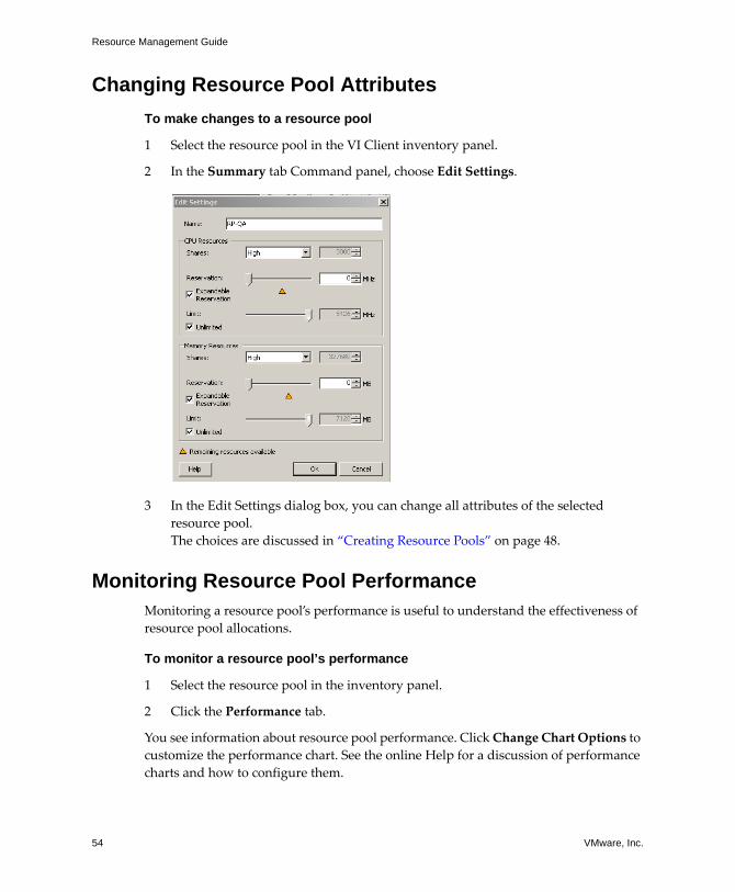
Resource Management Guide
54 VMware, Inc.
Changing Resource Pool Attributes
To make changes to a resource pool
1 Select the resource pool in the VI Client inventory panel.
2 In the Summary tab Command panel, choose Edit Settings.
3 In the Edit Settings dialog box, you can change all attributes of the selected
resource pool.
The choices are discussed in “Creating Resource Pools” on page 48.
Monitoring Resource Pool PerformanceMonitoring a resource pool’s performance is useful to understand the effectiveness of
resource pool allocations.
To monitor a resource pool’s performance
1 Select the resource pool in the inventory panel.
2 Click the Performance tab.
You see information about resource pool performance. Click Change Chart Options to
customize the performance chart. See the online Help for a discussion of performance
charts and how to configure them.

VMware, Inc. 55
Chapter 3 Understanding and Managing Resource Pools
Adding Virtual Machines to Resource PoolsWhen you create a new virtual machine, the Virtual Machine wizard allows you to add
it to a resource pool as part of the creation process. You can also add an already existing
virtual machine to a resource pool. This section discusses both tasks.
To create a virtual machine and add it to a resource pool
1 Select a host and choose File>New>Virtual Machine (or press Ctrl+n).
2 Supply the information for the virtual machine, choosing a resource pool as the
location when prompted by the wizard.
The wizard places the virtual machine into the resource pool you selected.
To add an existing virtual machine to a resource pool
1 Select the virtual machine from any location in the inventory.
The virtual machine can be associated with a standalone host, a cluster, or a
different resource pool.
2 Drag the virtual machine (or machines) to the resource pool object you want.
When you move a virtual machine to a new resource pool:
The virtual machine’s reservation and limit do not change.
If the virtual machine’s shares are high, medium, or low, %Shares adjusts to
reflect the total number of shares in use in the new resource pool.
If the virtual machine has custom shares assigned, the share value is
maintained.
The information displayed in the Resource Allocation tab about the resource
pool’s reserved and unreserved CPU and memory resources changes to reflect
the reservations associated with the virtual machine (if any).
NOTE Because share allocations are relative to a resource pool, you might
have to manually change a virtual machine’s shares when you move it into a
resource pool so that the virtual machine’s shares are consistent with the
relative values in the new resource pool. A warning appears if a virtual
machine would receive a very large (or very small) percentage of total shares.
NOTE If a virtual machine has been powered off or suspended, it can be
moved but overall available resources (such as reserved and unreserved CPU
and memory) for the resource pool are not affected.

Resource Management Guide
56 VMware, Inc.
If a virtual machine is powered on, and the destination resource pool does not have
enough CPU or memory to guarantee the virtual machine’s reservation, the move fails
because admission control does not allow it. An error dialog box explains the situation.
The error dialog box compares available and requested resources, so you can consider
whether an adjustment might resolve the issue. See “Resource Pool Admission
Control” on page 47.
Removing Virtual Machines from Resource PoolsYou can remove a virtual machine from a resource pool in a number of ways,
depending on your intention for the machine.
Move the virtual machine to a different resource pool. See “To add an existing virtual machine to a resource pool” on page 55. You do not need to power off a virtual
machine if you only move it.
When you remove a virtual machine from a resource pool, the total number of shares
associated with the resource pool decreases, so that each remaining share represents
more resources. For example, assume you have a pool that is entitled to 6GHz,
containing three virtual machines with shares set to Normal. Assuming the virtual
machines are CPU‐bound, each gets an equal allocation of 2GHz. If one of the virtual
machines is moved to a different resource pool, the two remaining virtual machines
each receive an equal allocation of 3GHz.
Remove the virtual machine from the inventory or delete it from the disk.
Right‐click the virtual machine (or press Delete).
You need to power off the virtual machine before you can completely remove it. See the
Virtual Infrastructure User’s Guide.
Resource Pools and ClustersWhen you add a host with an existing resource pool hierarchy to a cluster, what
happens depends on the cluster. You have two options:
“Clusters Enabled for DRS” on page 57
“Clusters Not Enabled for DRS” on page 58

VMware, Inc. 57
Chapter 3 Understanding and Managing Resource Pools
Clusters Enabled for DRS
If a cluster is enabled for DRS, and you move one or more hosts into the cluster, a
wizard allows you to choose what happens to the host’s resource pools.
Put this host’s virtual machines in the cluster’s root resources. Collapses the host’s resource pool hierarchy and makes all virtual machines direct children of the
cluster. This behavior is the same as that shown for “Clusters Not Enabled for DRS” on
page 58.
Create a new resource pool for the host’s virtual machines and resource pools.
Creates a resource pool corresponding to the host’s root resource pool. By default, the
resource pool is named Grafted from <host_name>, but you can choose a different
name. The term grafted was chosen because the branches of the host’s tree are added to
the branches of the cluster’s tree.
Figure 3-5. Resource Pool Hierarchy Grafted onto Cluster
In the example in Figure 3‐5, cluster Cluster and host Host1 each have a hierarchy of
resource pools. When you add the host to the cluster, the host’s invisible top‐level
resource pool is grafted onto the cluster’s resource pool hierarchy and is named grafted
from Host1 by default.
NOTE You might have to manually adjust the share values associated with
individual virtual machines because the shares in the original host hierarchy are
relative to the resource pools on the host.
NOTE Shares remain allocated as they were before the host moved into the cluster.
Percentages are adjusted as appropriate.
Z W Z W
Y
X
Y
X
RP
Host1cluster cluster GraftedfromHost1

Resource Management Guide
58 VMware, Inc.
The resource pool hierarchy becomes completely independent of the host. If you later
remove the host from the cluster, the cluster keeps the resource pool hierarchy and the
host loses the resource pool hierarchy (though the virtual machines are removed along
with the host). See “Removing Hosts from Clusters” on page 106.
Clusters Not Enabled for DRS
If the cluster is enabled for HA only (or neither HA nor DRS), and you move one or
more hosts into the cluster, the cluster takes ownership of the resources. The hosts and
virtual machines become associated with the cluster. The resource pool hierarchy is
flattened.
In Figure 3‐6, host H1 and host H2 each have a hierarchy of resource pools and virtual
machines. When the two hosts are added to cluster C, the resource pool hierarchy is
flattened and all virtual machines become direct children of the cluster.
Figure 3-6. Flattened Resource Pool Hierarchy
NOTE The host must be in maintenance mode before you can remove it from the
cluster. See “Host Maintenance and Standby Modes” on page 71.
NOTE In a non‐DRS cluster there is no cluster‐wide resource management based on
shares. Virtual machine shares remain relative to each host.
RP
RP
Host2
RP
Host1cluster cluster
RP RP
VM1 VM2 VM3 VM4
VM1 VM2 VM3 VM4

VMware, Inc. 59
4
This chapter presents a conceptual introduction to clusters and to the VMware
Distributed Resource Scheduler (DRS) and High Availability (HA) features.
This chapter discusses the following topics:
“Introduction to Clusters” on page 59
“Understanding VMware DRS” on page 62
“Understanding VMware HA” on page 72
“Using HA and DRS Together” on page 80
“Valid, Yellow, and Red Clusters” on page 81
Introduction to ClustersA cluster is a collection of ESX Server hosts and associated virtual machines with shared
resources and a shared management interface. When you add a host to a cluster, the
host’s resources become part of the cluster’s resources. When you create a cluster, you
can choose to enable it for DRS, HA, or both.
See “Cluster Prerequisites” on page 89 for information on the virtual machines in
clusters and on how to configure them.
Understanding Clusters 4
NOTE All tasks described assume you have permission to perform them. See the online
Help for information on permissions and how to set them.
NOTE You can create a cluster without a special license, but you must have a license to
enable a cluster for DRS or HA.

Resource Management Guide
60 VMware, Inc.
VMware DRS
The DRS feature improves resource allocation across all hosts and resource pools. DRS
collects resource usage information for all hosts and virtual machines in the cluster and
generates recommendations for virtual machine placement and host machine power
state. These recommendations can be applied automatically. Depending on the
configured DRS automation level, DRS displays or applies the following types of
recommendations:
Initial placement — When you first power on a virtual machine in the cluster, DRS
either places the virtual machine on an appropriate host or makes a
recommendation. See “Initial Placement” on page 62.
Migration— At runtime, DRS tries to fix rule violations and improve resource
utilization across the cluster either by performing migrations of virtual machines,
or by providing recommendations for virtual machine migrations. See “Load
Balancing and Virtual Machine Migration” on page 66.
Power management — When the Distributed Power Management feature is
enabled, DRS compares cluster‐ and host‐level capacity to the demands of running
the cluster’s virtual machines, including recent historical demand. It makes
recommendations for placing hosts in standby power mode if sufficient excess
capacity is found or powering on hosts if capacity is needed. Depending on the
resulting host power state recommendations, virtual machines might need to be
migrated to and from the hosts as well. See “Distributed Power Management” on
page 68.
VMware HA
A cluster enabled for HA monitors for host failure. If a host becomes unavailable, all
virtual machines that were on the host are promptly restarted on different hosts.
When you enable a cluster for HA, you can specify the number of host failures allowed.
If you set the number of host failures as 1, HA maintains enough capacity across the
cluster to tolerate the failure of one host, so that all running virtual machines on that
host can be restarted on remaining hosts. By default, you cannot power on a virtual
machine if doing so violates required failover capacity (strict admission control). See
“Understanding VMware HA” on page 72.

VMware, Inc. 61
Chapter 4 Understanding Clusters
Figure 4-1. VMware HA
In Figure 4‐1, three hosts have three virtual machines each, and the corresponding HA
cluster is configured for failover of one host. When Host B becomes unavailable, HA
migrates the virtual machines from Host B to Host A and Host C.
Clusters and VirtualCenter Failure
The VirtualCenter Server places an agent on each host. If the VirtualCenter Server
becomes unavailable, HA and DRS functionality changes as follows:
HA—HA clusters continue to work even if the VirtualCenter Server becomes
unavailable, and can still restart virtual machines on other hosts in case of failover.
However, the information about virtual machine specific cluster properties (such
as VM restart priority and host isolation response) is based on the state of the
cluster before the VirtualCenter Server went down.
DRS—The hosts in DRS clusters continue running using available resources.
However, there are no recommendations for resource optimization.
If you must make changes to the hosts or virtual machines using a VI Client connected
to an ESX Server host while the VirtualCenter Server is unavailable, those changes do
take effect. When VirtualCenter becomes available again, you might find that clusters
have turned red or yellow because cluster requirements are no longer met.
Host A
VM1 VM2 VM3
Host A
VM1 VM2 VM3
Host A
VM1
VM4
VM2
VM6
VM3
Host B
VM4 VM5 VM6
Host B
VM4 VM5 VM6
Host C
VM7 VM8 VM9
Host C
VM7 VM8 VM9
Host C
VM7
VM5
VM8 VM9
All three hosts run One host goes down The affected virtualmachines have been
restarted on theremaining hosts
Resource Management Guide
62 VMware, Inc.
Understanding VMware DRSWhen you enable a cluster for DRS, VirtualCenter continuously monitors the
distribution of CPU and memory resources for all hosts and virtual machines in the
cluster. DRS compares these metrics to what resource utilization ideally should be
given the attributes of the resource pools and virtual machines in the cluster and the
current demand and makes migration recommendations accordingly. Also, when the
Distributed Power Management feature is enabled, DRS monitors the cluster‐ and
host‐level capacity available for running virtual machines and makes
recommendations about powering hosts off or on based on whether capacity is found
to be excessive or lacking.
When you add a host to a DRS cluster, that host’s resources become associated with the
cluster. The system prompts you whether you want to associate any existing virtual
machines and resource pools with the cluster’s root resource pool or graft the resource
pool hierarchy. See “Resource Pools and Clusters” on page 56. VirtualCenter can then
perform initial placement of virtual machines, virtual machine migration for the sake
of load balancing or rule enforcement, and distributed power management (if enabled).
Initial Placement
When you attempt to power on a single virtual machine or a group of virtual machines
in a DRS‐enabled cluster, VirtualCenter checks that there are enough resources in the
cluster to support the virtual machine(s). Then, for each virtual machine, VirtualCenter
identifies a host on which it can run and does one of the following:
Automatically places it. If all placement‐related actions (virtual machines being
powered on or migrated, or hosts being powered on) are in automatic mode, these steps
are taken automatically with no recommendation being shown to the user.
Makes an initial placement recommendation. If the automation level of any of the
placement‐related actions are in manual mode. Initial placement recommendations
received by users in nonautomatic placement scenarios differ based on whether one or
more than one virtual machine is being powered on.
NOTE No initial placement recommendations are given for virtual machines on
standalone hosts or in non‐DRS clusters. When powered on, they are placed on the host
where they currently reside.

VMware, Inc. 63
Chapter 4 Understanding Clusters
Single Virtual Machine Power On
When a single virtual machine is being powered on, you have two types of initial
placement recommendations:
A single virtual machine is being powered on and no prerequisite steps are
needed.
The user is presented with a list of mutually exclusive initial placement
recommendations for the virtual machine (Figure 4‐2). You can choose only one.
Figure 4-2. Single Virtual Machine, No Prerequisites
A single virtual machine is being powered on, but prerequisite actions are
required.
These actions include powering on a host in standby mode or the migration of
other virtual machines from one host to another. In this case, only one
recommendation is provided and it has multiple lines, showing each of the
prerequisite actions. The user can either accept this entire recommendation or
cancel powering on the virtual machine (Figure 4‐3).
Figure 4-3. Single Virtual Machine, with Prerequisites

Resource Management Guide
64 VMware, Inc.
Group Power On
You can attempt to power on multiple virtual machines at the same time (group power
on). It is not required that the virtual machines selected for a group power‐on attempt
be in the same DRS cluster. They can be selected across clusters but must be within the
same datacenter. It is also possible to include virtual machines located in non‐DRS
clusters or on standalone hosts, but these are powered on automatically and not
included in any initial placement recommendation.
The initial placement recommendations for group power‐on attempts are provided on
a per‐cluster basis. If all of the placement‐related actions for a group power‐on attempt
are in automatic mode, the virtual machines are powered on with no initial placement
recommendation given. If placement‐related actions for any of the virtual machines are
in manual mode, the powering on of all of the virtual machines (including those that
are in automatic mode) is manual and is included in an initial placement
recommendation.
For each DRS cluster that the virtual machines being powered on belong to, there is a
single recommendation, which contains all of the needed prerequisites (or no
recommendation). All such cluster‐specific recommendations are presented together
under the Power On Recommendations tab (Figure 4‐4).
Figure 4-4. Group Power On Recommendation

VMware, Inc. 65
Chapter 4 Understanding Clusters
When a nonautomatic group power‐on attempt is made, and virtual machines not
subject to an initial placement recommendation (that is, those on standalone hosts or in
non‐DRS clusters) are included, VirtualCenter attempts to power them on
automatically. If these power ons are successful, they are listed under the Started
Power‐Ons tab. Any virtual machines that fail to power on in this way are listed under
the Failed Power‐Ons tab. See Figure 4‐5.
Figure 4-5. Automatic Group Power On
Group Power‐On Example: The user selects three virtual machines in the same datacenter
for a group power‐on attempt. The first two virtual machines (VM1 and VM2) are in the
same DRS cluster (Cluster1), while the third virtual machine (VM3) is on a standalone
host. VM1 is in automatic mode and VM2 is in manual mode. For this scenario, the user
is presented with an initial placement recommendation for Cluster1 (under the Power
On Recommendations tab) which consists of actions for powering on VM1 and VM2.
An attempt is made to power on VM3 automatically and, if successful, it is listed under
the Started Power Ons tab. If this attempt fails, it is listed under the Failed Power Ons
tab.
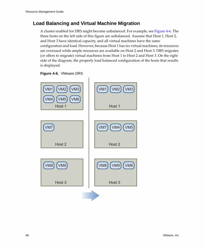
Resource Management Guide
66 VMware, Inc.
Load Balancing and Virtual Machine Migration
A cluster enabled for DRS might become unbalanced. For example, see Figure 4‐6. The
three hosts on the left side of this figure are unbalanced. Assume that Host 1, Host 2,
and Host 3 have identical capacity, and all virtual machines have the same
configuration and load. However, because Host 1 has six virtual machines, its resources
are overused while ample resources are available on Host 2 and Host 3. DRS migrates
(or offers to migrate) virtual machines from Host 1 to Host 2 and Host 3. On the right
side of the diagram, the properly load balanced configuration of the hosts that results
is displayed.
Figure 4-6. VMware DRS
Host 1
VM1
VM4
VM2 VM3
VM5 VM6
Host 2
VM7
Host 3
VM8 VM9
Host 1
VM1 VM2 VM3
Host 2
VM7 VM4 VM5
Host 3
VM8 VM9 VM6

VMware, Inc. 67
Chapter 4 Understanding Clusters
When a cluster becomes unbalanced, DRS makes recommendations or migrates virtual
machines, depending on the default automation level:
If the cluster or any of the virtual machines involved are manual or partially
automated, VirtualCenter does not take automatic actions to balance resources.
Instead, the Summary page indicates that migration recommendations are
available and the DRS Recommendations page displays recommendations for
changes that make the most efficient use of resources across the cluster.
If the cluster and virtual machines involved are all fully automated, VirtualCenter
migrates running virtual machines between hosts as needed to ensure efficient use
of cluster resources.
By default, automation level is specified for the whole cluster. You can also specify a
custom automation level for individual virtual machines.
Migration Threshold
The migration threshold allows you to specify which recommendations are applied
when the cluster is in fully automated mode. See Figure 4‐7. You can move the slider to
use one of five levels, ranging from “Conservative,” which makes the smallest number
of migrations, to “Aggressive,” which makes the largest number of migrations. The five
migration levels apply recommendations based on their assigned star ratings.
Figure 4-7. Migration Threshold Choices
NOTE Even in an automatic migration setup, users can explicitly migrate
individual virtual machines, but VirtualCenter might move those virtual machines
to other hosts to optimize cluster resources.
Resource Management Guide
68 VMware, Inc.
Star ratings are assigned to migration recommendations based on the amount of
improvement in the cluster’s load balance that they bring—ranging from five‐star
recommendations, which are mandatory, to one‐star recommendations, which bring
only a slight improvement. Each level you move the slider to the right allows the
inclusive application of one more lower level of star ratings. The Conservative setting
applies only five‐star recommendations, the next level to the right applies four‐star
recommendations and higher, and so on, down to the Aggressive level which applies
one‐star recommendations and higher (that is, it applies all recommendations.)
Migration Recommendations
If you create a cluster with a default manual or partially automated mode,
VirtualCenter displays migration recommendations on the DRS Recommendations
page. The system supplies as many recommendations as necessary to enforce rules and
balance the resources of the cluster. Each recommendation includes the virtual machine
to be moved, current (source) host and destination host, and a reason for the
recommendation. The reason can be one of the following:
Balance average CPU loads.
Balance average memory loads.
Satisfy resource pool reservations.
Satisfy affinity (or anti‐affinity) rule. See “Using DRS Affinity Rules” on page 110.
Host is entering maintenance mode. See “Host Maintenance and Standby Modes”
on page 71.
Distributed Power Management
When this experimental feature is enabled, a DRS cluster can reduce its power
consumption by making recommendations based on a comparison of cluster‐level
capacity versus demand. If capacity is deemed to be inadequate, DRS recommends
powering on hosts and migrating virtual machines (using VMware VMotion™) to
them. Conversely, when excess capacity is found, DRS recommends that some hosts be
placed in standby mode and any virtual machines running on them are evacuated to
other hosts. See “Standby Mode” on page 72. Whether these host power state and
migration recommendations are executed automatically depends upon the automation
level selected for the Distributed Power Management feature.

VMware, Inc. 69
Chapter 4 Understanding Clusters
Before Distributed Power Management can be enabled for a DRS cluster, you must
ensure that the ESX Server hosts have the appropriate hardware support and
configuration. Specifically, the NICs used by the VMkernel network must have
Wake‐on‐LAN (WOL) functionality, which is used to bring an ESX Server host up from
a powered‐off state. You should test wake capability operation on each ESX Server 3.5
(or ESX Server 3i version 3.5) host on which Distributed Power Management is to be
deployed. To do this, ensure that there is at least one other ESX Server host powered on
in the cluster (to send the wake packets), explicitly put the host to be tested into standby
state and once it has entered, ensure that explicitly requesting that the standby host
power back on is successful. If not, VMware recommends that you do not configure it
to be power managed by Distributed Power Management.
The default power management automation level for a DRS cluster is selected from the
Power Management tab of the cluster’s Settings dialog box. See Figure 4‐8. The feature
is enabled whenever this setting is not “off.” The options available are:
Off – The feature is disabled and no recommendations will be made.
Manual – Host power operation and related virtual machine migration
recommendations are made, but not automatically executed.
Automatic – Host power operations are automatically executed if related virtual
machine migrations can all be executed automatically.
In addition to these cluster‐level settings, you can also set overrides for individual hosts
so that their automation level differs from that of the cluster. Such overrides only apply
if the feature is enabled (not set to “off”) for the cluster.
CAUTION Before implementing Distributed Power Management, test the
Wake‐on‐LAN capability of your hosts. If WOL functionality fails, the power
management feature may power off hosts and not be able to power them back on later.

Resource Management Guide
70 VMware, Inc.
Figure 4-8. Power Management Automation Level and Host Overrides
DRS Clusters, Resource Pools, and ESX Server
For clusters enabled for DRS, the resources of all hosts are assigned to the cluster.
DRS internally uses the per‐host resource pool hierarchies to implement the
cluster‐wide resource pool hierarchy. When you view the cluster using a VI Client
connected to a VirtualCenter Server, you see the resource pool hierarchy implemented
by DRS.
When you view individual hosts using a VI Client connected to an ESX Server host, the
underlying hierarchy of resource pools is presented. Because DRS implements the most
balanced resource pool hierarchy it can, do not modify the hierarchy visible on the
individual ESX Server host. If you do, DRS will undo your changes immediately.
NOTE The power management automation level is not the same as the DRS automation
level (for load balancing) described earlier. Also, the recommendations generated by
Distributed Power Management are assigned star ratings to show their relative
importance, but they are not controlled by the DRS migration threshold.

VMware, Inc. 71
Chapter 4 Understanding Clusters
Host Maintenance and Standby Modes
Maintenance mode and standby mode for hosts have similarities. In particular, they
prohibit the running of virtual machines. However, the two modes have distinct
purposes. You move a host into maintenance mode, when you need to service it—for
example, by installing more memory or upgrading the version of ESX Server running
on it—and the host remains in maintenance mode until you move it out. In contrast,
DRS moves hosts into and out of standby mode automatically, to optimize power
usage.
Maintenance Mode
Standalone hosts and hosts within a cluster support a maintenance mode, which
restricts the virtual machine operations on the host to allow you to shut down running
virtual machines in preparation for host shut down. Only ESX Server 3.0 and later
supports maintenance mode for standalone hosts.
A host enters or leaves maintenance mode only as the result of a user request. If the host
is in a cluster, when it enters maintenance mode the user is given the option to evacuate
powered‐off virtual machines. If this option is selected, each powered‐off virtual
machine is migrated to another host, unless there is no compatible host available for the
virtual machine in the cluster. While in maintenance mode, the host does not allow you
to deploy or power on a virtual machine. Virtual machines that are running on a host
entering maintenance mode need to be either migrated to another host or shut down
(either manually or automatically by DRS).
When no more running virtual machines are on the host, the host’s icon changes to
include under maintenance and the host’s Summary panel indicates the new state.
NOTE No virtual machine migrations will be recommended (or performed, in fully
automated mode) off of a host entering maintenance or standby mode if the VMware
HA failover level would be violated after the host enters the requested mode. This
restriction applies whether strict HA admission control is enabled or not.
NOTE If DRS can make no migration recommendations for a virtual machine, an event
is generated (check the virtual machine’s Tasks & Events tab). The virtual machine must
be migrated manually or powered off before the host can enter maintenance mode.

Resource Management Guide
72 VMware, Inc.
The default automation mode of a virtual machine determines its behavior when the
host (in a DRS cluster) it is running on enters maintenance mode:
Any fully automated virtual machine is migrated automatically.
For a partially automated or manual virtual machine, a recommendation for
further user action is generated and displayed.
Standby Mode
When a host machine is placed in standby mode, it is powered off. Normally, hosts are
placed in standby mode by the distributed power management feature. You can also
place a host in standby mode manually; however, DRS might undo (or recommend
undoing) your change the next time it runs. To force a host to remain off, place it in
maintenance mode and power it off. You can also disable distributed power
management (or set it to manual mode) on the host to prevent the host from being
automatically powered on.
If the distributed power management feature determines that the host needs to be
brought out of standby mode (that is, to be powered back on), this is done using
Wake‐on‐LAN technology.
To accommodate this, you must ensure that the following steps are taken:
The NIC that the VMkernel networking stack is attached to (selected as the
VMotion NIC) must be WOL‐compatible. To display the WOL‐compatibility status
for each NIC on a host, select the host in the inventory panel of the VI Client,
choose the Configuration tab, and click Network Adapters.
The VMotion network must be on a single IP subnet per cluster.
Understanding VMware HAThe HA cluster feature allows the virtual machines running on ESX Server systems to
automatically recover from host failures. When a host becomes unavailable, all
associated virtual machines are immediately restarted on other hosts in the system.
This section first considers differences between VMware HA clusters and traditional
clustering solutions, and presents HA cluster concepts.
NOTE If no appropriate host is available, DRS displays information on the Tasks
& Events tab.
NOTE Hosts that do not have WOL‐compatible NICs are never selected for standby
mode.
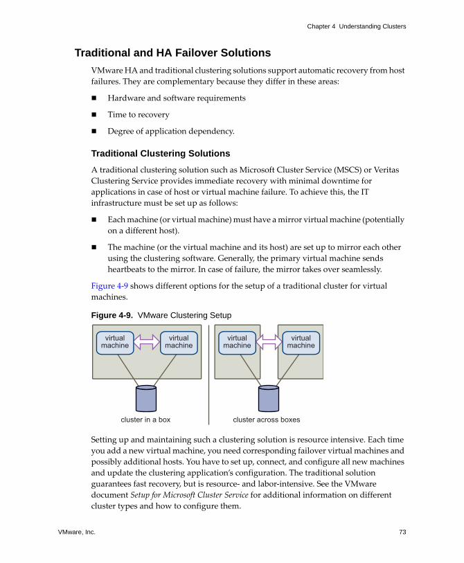
VMware, Inc. 73
Chapter 4 Understanding Clusters
Traditional and HA Failover Solutions
VMware HA and traditional clustering solutions support automatic recovery from host
failures. They are complementary because they differ in these areas:
Hardware and software requirements
Time to recovery
Degree of application dependency.
Traditional Clustering Solutions
A traditional clustering solution such as Microsoft Cluster Service (MSCS) or Veritas
Clustering Service provides immediate recovery with minimal downtime for
applications in case of host or virtual machine failure. To achieve this, the IT
infrastructure must be set up as follows:
Each machine (or virtual machine) must have a mirror virtual machine (potentially
on a different host).
The machine (or the virtual machine and its host) are set up to mirror each other
using the clustering software. Generally, the primary virtual machine sends
heartbeats to the mirror. In case of failure, the mirror takes over seamlessly.
Figure 4‐9 shows different options for the setup of a traditional cluster for virtual
machines.
Figure 4-9. VMware Clustering Setup
Setting up and maintaining such a clustering solution is resource intensive. Each time
you add a new virtual machine, you need corresponding failover virtual machines and
possibly additional hosts. You have to set up, connect, and configure all new machines
and update the clustering application’s configuration. The traditional solution
guarantees fast recovery, but is resource‐ and labor‐intensive. See the VMware
document Setup for Microsoft Cluster Service for additional information on different
cluster types and how to configure them.
virtualmachine
cluster in a box cluster across boxes
virtualmachine
virtualmachine
virtualmachine

Resource Management Guide
74 VMware, Inc.
VMware HA Solution
In a VMware HA solution, a set of ESX Server hosts is combined into a cluster with a
shared pool of resources. VirtualCenter monitors all hosts in the cluster. If one of the
hosts fails, VirtualCenter immediately responds by restarting each associated virtual
machine on a different host.
Using VMware HA has a number of advantages:
Minimal setup — The New Cluster Wizard is used for initial setup. You can add
hosts and new virtual machines using the VI Client. All virtual machines in the
cluster get failover support without additional configuration.
Reduced hardware cost and setup — In a traditional clustering solution, duplicate
hardware and software must be connected and configured properly. The virtual
machine acts as a portable container for the applications, and can be moved
around. Duplicate configurations on multiple machines can be avoided. When you
use VMware HA, you must have sufficient resources to fail over the number of
hosts you want to guarantee. However, the VirtualCenter Server takes care of the
resource management and cluster configuration.
Increased application availability — Any application running inside a virtual
machine has access to increased availability. Because the virtual machine can
recover from hardware failure, all applications that are set up to start during the
boot cycle have increased availability at no extra cost even if the application is not
itself a clustered application.
Potential limitations of using HA clusters include loss of run‐time state and a longer
application downtime than in a traditional clustering environment with hot standby. If
those limitations become issues, consider using the two approaches together.
VMware HA Features
A cluster enabled for HA:
Supports easy‐to‐use configuration using the VI Client.
Provides failover on hardware failure for all running virtual machines within the
bounds of failover capacity (see “Failover Capacity” on page 75).
Works with traditional application‐level failover and enhances it.
Is fully integrated with DRS. If a host has failed and virtual machines have been
restarted on other hosts, DRS can provide migration recommendations or migrate
virtual machines for balanced resource allocation. If one or both of the source and
destination hosts of a migration fail, HA can help recover from that failure.

VMware, Inc. 75
Chapter 4 Understanding Clusters
Failover Capacity
When you enable a cluster for HA, the New Cluster wizard prompts you for the
number of hosts for which you want failover capacity. This number is shown as the
Configured Failover Capacity in the VI Client. HA uses this number to determine if
there are enough resources to power on virtual machines in the cluster.
You need to specify only the number of hosts for which you want failover capacity. HA
computes the resources it requires to fail over virtual machines for that many hosts,
using a conservative estimate, and disallows powering on virtual machines if failover
capacity can no longer be guaranteed.
After you have created a cluster, you can add hosts to it. When you add a host to an HA
cluster that is not enabled for DRS, all resource pools are immediately removed from
the host, and all virtual machines become directly associated with the cluster.
Planning for HA Clusters
When planning an HA cluster, consider the following:
Each host has some memory and CPU to power on virtual machines.
Each virtual machine must be guaranteed its CPU and memory reservation
requirements.
In general, using a uniform setup is recommended. HA plans for a worst‐case failure
scenario. When computing required failover capacity, HA calculates the maximum
memory and CPU reservations needed for any currently powered on virtual machine
and calls this a slot. A slot is the amount of CPU and memory resources that will be
sufficient for any currently powered on virtual machine (powered off or suspended
virtual machines are not considered when calculating the current failover level).
NOTE (SEE UPDATE) You can allow the cluster to power on virtual machines even when
they violate availability constraints. If you do that, the result is a red cluster, which
means that failover guarantees might no longer be valid. See “Valid, Yellow, and Red
Clusters” on page 81.
NOTE If the cluster is also enabled for DRS, you can choose to keep the resource pool
hierarchy. See “Resource Pools and Clusters” on page 56.

Resource Management Guide
76 VMware, Inc.
For example, if you have a virtual machine with 1GHz CPU reservation and 1GB
memory reservation and another virtual machine with 2GHz CPU reservation and
512MB memory reservation, the slot is defined as 2GHz CPU reservation and 1GB
memory reservation. HA determines how many slots can “fit” into each host based on
the host’s CPU and memory capacity. HA then determines how many hosts could fail
with the cluster still having at least as many slots as powered on virtual machines. This
number is the current failover level.
During planning, decide on the number of hosts for which you want to guarantee
failover. HA tries to reserve resources for at least as many host failures by limiting the
number of virtual machines that are powered on, which will consume these resources.
If you left the Allow virtual machine to be started even if they violate availability
constraints option unselected (strict admission control), VMware HA does not allow
you to power on virtual machines if they would cause the current failover level to
become less than the configured failover level. VMware HA also does not allow the
following operations if they would cause the current failover level to exceed the
configured failover level:
Reverting a powered off virtual machine to a powered on snapshot.
Migrating a running virtual machine into the cluster.
Reconfiguring a running virtual machine to increase its CPU or memory
reservation.
If you selected the Allow virtual machine to be started even if they violate availability
constraints option when you enable HA, you can power on more virtual machines than
HA would advise. Because you configured the system to permit this, the cluster does
not turn red. The current (available) failover level can also fall below the configured
failover level if the number of hosts that have failed exceeds the configured number. For
example, if you have configured the cluster for a one host failure, you are at capacity
(the current failover level is equal to the configured failover level), and two hosts fail,
the cluster turns red.
A cluster that is beneath the configured failover level can still perform virtual machine
failover in case of host failure, using virtual machine priority to determine which
virtual machines to power on first. See “Customizing HA for Virtual Machines” on
page 117.
CAUTION It is not recommended that you work with red clusters. If you do, failover is
not guaranteed at the specified level.

VMware, Inc. 77
Chapter 4 Understanding Clusters
VMware HA and Special Situations
VMware HA understands how to work with special situations to preserve your data:
Power off host. If you power off a host, HA restarts any virtual machines running on
that host on a different host.
Migrate virtual machine with VMotion. If you are migrating a virtual machine to
another host using VMotion, and the source or destination host become unavailable,
the virtual machine could be left in a failed (powered off) state depending on the stage
in the migration. HA handles this failure and powers on the virtual machine on an
appropriate host:
If the source host becomes unavailable, HA powers on the virtual machine on
the destination host.
If the destination host becomes unavailable, HA powers on the virtual
machine on the source host.
If both hosts become unavailable, HA powers on the virtual machine on a
third host in the cluster if it exists.
Current failover capacity does not match configured failover capacity. A cluster turns red if current failover capacity is smaller than configured failover capacity. This
can happen because more hosts failed than you configured the cluster to tolerate. If you
turned off strict admission control, the cluster will not turn red, even if you power on
more virtual machines than can be accommodated.
When there is insufficient capacity, HA fails over virtual machines with higher
priorities first, then attempts to fail over other virtual machines. In this case, give high
priorities to virtual machines that are most critical to your environment for recovery.
See “Customizing HA for Virtual Machines” on page 117.
Host network isolation. A host in an HA cluster might lose its console network (or
VMkernel network, in ESX Server 3i) connectivity. Such a host is isolated from other
hosts in the cluster. Other hosts in the cluster consider that host failed and attempt to
fail over its running virtual machines. If a virtual machine continues to run on the
isolated host, VMFS disk locking prevents it from being powered on elsewhere. If
virtual machines share the same network adapter, they will not have access to the
network. You might want to start the virtual machine on another host.
By default, virtual machines are left powered on. You can change the cluster’s default
behavior to shut down the virtual machines on the isolated host or to power them off.
You can also change that behavior for each virtual machine. See “Customizing HA for
Virtual Machines” on page 117.

Resource Management Guide
78 VMware, Inc.
Primary and Secondary Hosts
Some of the hosts in an HA cluster are designated as primary hosts and they maintain
the metadata and failover intelligence. The first five hosts in the cluster become primary
hosts, all others are secondary hosts. When you add a host to an HA cluster, that host has
to communicate with an existing primary host in the same cluster to complete its
configuration (unless it’s the first host in the cluster, which makes it the primary host).
When a primary host becomes unavailable or is removed, HA promotes another host
to primary status. Primary hosts help to provide redundancy and are used to initiate
failover actions.
If all the hosts in the cluster are not responding, and you add a new host to the cluster,
HA configuration fails because the new host cannot communicate with any of the
primary hosts. In this situation, you must disconnect all the hosts that are not
responding before you can add the new host. The new host becomes the first primary
host. When the other hosts become available again, their HA service is reconfigured
and they then become primary or secondary hosts depending on the existing number
of primary hosts.
HA Clusters and Maintenance Mode
When you put a host in maintenance mode, you are preparing to shut it down or do
maintenance on it. You cannot power on a virtual machine on a host that is in
maintenance mode. In the event of a host failure, HA does not fail over any virtual
machines to a host that is in maintenance mode. Such a host is not considered when HA
computes the current failover level.
When a host exits maintenance mode, the HA service is reenabled on that host, so it
becomes available for failover again.
When a host is entering maintenance mode, if it does not have any powered‐on virtual
machines, this transition to maintenance mode cannot be cancelled.
HA Clusters and Disconnected Hosts
When a host becomes disconnected, it exists in the VirtualCenter inventory, but
VirtualCenter does not get any updates from that host, does not monitor it, and has no
knowledge of the health of that host. Because the status of the host is not known, and
because VirtualCenter is not communicating with that host, HA cannot use it as a
guaranteed failover target. HA does not consider disconnected hosts when computing
the current failover level.
When the host becomes reconnected, the host becomes available for failover again.

VMware, Inc. 79
Chapter 4 Understanding Clusters
The difference between a disconnected host and a host that is not responding is
described in the list.
A disconnected host has been explicitly disconnected by the user. As part of
disconnecting a host, VirtualCenter disables HA on that host. The virtual machines
on that host are not failed over and not considered when VirtualCenter computes
the current failover level.
If a host is not responding, the VirtualCenter Server no longer receives heartbeats
from it. This might happen, for example, because of a network problem, because
the host failed, or because the VirtualCenter agent failed.
VirtualCenter does not include such hosts when computing the current failover
level, but assumes that any virtual machines running on a nonresponding host will
be failed over if the host fails. The virtual machines on a host that is not responding
affect the admission control check.
HA Clusters and Host Network Isolation
Host failure detection occurs 15 seconds after the HA service on a host has stopped
sending heartbeats to the other hosts in the cluster. (The default value of this failure
detection interval can be changed. See “Setting Advanced HA Options” on page 126.)
A host stops sending heartbeats if it fails or if it is isolated from the network. At that
time, other hosts in the cluster treat this host as failed, while this host declares itself as
isolated from the network after it has lost network connectivity for more than 12
seconds.
If the isolated host has SAN access, it retains the disk lock on the virtual machine files,
and any attempts to fail over the virtual machine to another host fails. The virtual
machine continues to run on the isolated host. VMFS disk locking prevents
simultaneous write operations to the virtual machine disk files and potential
corruption. By default, the isolated host leaves its virtual machines powered on.
If the network connection is restored before 12 seconds have elapsed, other hosts in the
cluster do not treat this as a host failure. It is treated as transient. In addition, the host
with the transient network connection problem does not declare itself isolated from the
network and continues running.
If the network connection is not restored for 15 seconds or longer, the other hosts in the
cluster treat the host as failed and attempt to fail over the virtual machines on that host.
The isolated host powers down its virtual machines so they can be restarted on other
hosts that have functioning network connectivity.

Resource Management Guide
80 VMware, Inc.
In the window between 12 and 14 seconds, the clustering service on the isolated host
declares itself as isolated and take steps based on the host isolation response settings. If
the network connection is restored during that time, the virtual machine that had been
powered off is not restarted on other hosts because the HA services on the other hosts
do not consider this host as failed yet.
As a result, if the network connection is restored in this window between 12 and
14 seconds after the host has lost connectivity, the virtual machines are powered off but
not failed over.
Using HA and DRS TogetherWhen HA performs failover and restarts virtual machines on different hosts, its first
priority is the immediate availability of all virtual machines. After the virtual machines
have been restarted, those hosts on which they were powered on might be heavily
loaded, while other hosts are comparatively lightly loaded. HA uses the CPU and
memory reservation to determine failover, while the actual usage might be higher.
Using HA and DRS together combines automatic failover with load balancing. This
combination can result in a fast rebalancing of virtual machines after HA has moved
virtual machines to different hosts. You can set up affinity and anti‐affinity rules to start
two or more virtual machines preferentially on the same host (affinity) or on different
hosts (anti‐affinity). For example, you can use an anti‐affinity rule to ensure that two
virtual machines running a critical application never run on the same host. See “Using
DRS Affinity Rules” on page 110.
NOTE In a cluster using DRS and HA with HA admission control turned on, virtual
machines might not be evacuated from hosts entering maintenance mode. This is
because of the resources reserved to maintain the failover level. In this case, you must
manually migrate the virtual machines off of the hosts using VMotion.

VMware, Inc. 81
Chapter 4 Understanding Clusters
Valid, Yellow, and Red ClustersThe VI Client indicates whether a cluster is valid, overcommitted (yellow), or invalid
(red). Clusters can become overcommitted because of a DRS violation. Clusters can
become invalid because of a DRS violation or an HA violation. A message displayed in
the Summary page indicates the issue.
Valid Cluster
A valid cluster has enough resources to meet all reservations and to support all running
virtual machines. A cluster is valid unless something happens that makes it
overcommitted or invalid.
A DRS cluster can become overcommitted if a host fails.
A DRS cluster can become invalid if VirtualCenter is unavailable and you power
on virtual machines using a VI Client connected directly to an ESX Server host.
An HA cluster becomes invalid if the current failover capacity is lower than the
configured failover capacity or if all the primary hosts in the cluster are not
responding. See “Primary and Secondary Hosts” on page 78.
A DRS or HA cluster can become invalid if the user reduces the reservation on a
parent resource pool while a virtual machine is in the process of failing over.
Before considering the following examples, note the definition of these terms:
Reservation (for a resource pool)—A fixed, guaranteed allocation for the resource
pool input by the user.
Reservation Used (for a cluster or resource pool)—The sum of the reservation or
reservation used (whichever is larger) for each child, added recursively.
Unreserved (for a cluster or resource pool)—A nonnegative number that also
differs according to resource pool type:
For a cluster it equals total capacity ‐ reservation used.
For nonexpandable resource pools it equals reservation ‐ reservation used.
For expandable resource pools it is equal to (reservation ‐ reservation used) +
any unreserved resources that can be borrowed from its ancestor resource
pools.

Resource Management Guide
82 VMware, Inc.
Example 1: Valid Cluster, All Resource Pools of Type Fixed
Figure 4‐10 shows a valid cluster and how its CPU resources are computed. The cluster
has the following characteristics:
A cluster with total resources of 12GHz.
Three resource pools, each of type Fixed (Expandable Reservation is not selected).
The total reservation of the three resource pools combined is 11GHz (4+4+3 GHz).
The total is shown in the Reservation Used field for the cluster.
RP1 was created with a reservation of 4GHz. Two virtual machines. (VM1 and
VM7) of 2GHz each are powered on (Reservation Used: 4GHz). No resources are
left for powering on additional virtual machines. VM6 is shown as not powered on.
It consumes none of the reservation.
RP2 was created with a reservation of 4GHz. Two virtual machines of 1GHz and
2GHz are powered on (Reservation Used: 3GHz). 1GHz remains unreserved.
RP3 was created with a reservation of 3GHz (Reservation). One virtual machine
with 3GHz is powered on. No resources for powering on additional virtual
machines are available.
Figure 4-10. Valid Cluster (Fixed Resource Pools)
clusterTotal Resources: 12G
Reservation Used: 11GUnreserved: 1G
RP1Reservation: 4G
Reservation Used: 4GUnreserved: 0G
RP2Reservation: 4G
Reservation Used: 3GUnreserved: 1G
RP3Reservation: 3G
Reservation Used: 3GUnreserved: 0G
VM1, 2G
VM7, 2G
VM2, 2G
VM4, 1G VM8, 2G
VM3, 3G VM5, 2GVM6, 2G

VMware, Inc. 83
Chapter 4 Understanding Clusters
Example 2: Valid Cluster, Some Resource Pools of Type Expandable
Example 2 (Figure 4‐11) uses similar settings to Example 1. However, RP1 and RP3 use
reservation type Expandable. A valid cluster can be configured as follows:
A cluster with total resources of 16GHz.
RP1 and RP3 are of type Expandable, RP2 is of type Fixed.
The total reservation used of the three resource pools combined is 16GHz (6GHz
for RP1, 5GHz for RP2, and 5GHz for RP3). 16GHz shows up as the Reservation
Used for the cluster at top level.
RP1 was created with a reservation of 4GHz. Three virtual machines of 2GHz each
are powered on. Two of those virtual machines (for example, VM1 and VM7) can
use RP1’s reservations, the third virtual machine (VM6) can use reservations from
the cluster’s resource pool. (If the type of this resource pool were Fixed, you could
not power on the additional virtual machine.)
RP2 was created with a reservation of 5GHz. Two virtual machines of 1GHz and
2GHz are powered on (Reservation Used: 3GHz). 2GHz remains unreserved.
RP3 was created with a reservation of 5GHz. Two virtual machines of 3GHz and
2GHz are powered on. Even though this resource pool is of type Expandable, no
additional 2GHz virtual machine can be powered on because the parent’s extra
resources are already used by RP1.
Figure 4-11. Valid Cluster (Expandable Resource Pools)
clusterTotal Resources: 16G
Reservation Used: 16GUnreserved: 0G
RP1 (expandable)Reservation: 4G
Reservation Used: 6GUnreserved: 0G
RP2Reservation: 5G
Reservation Used: 3GUnreserved: 2G
RP3 (expandable)Reservation: 5G
Reservation Used: 5GUnreserved: 0G
VM1, 2G
VM7, 2G
VM2, 2G
VM4, 1G VM8, 2G
VM3, 3G VM5, 2GVM6, 2G

Resource Management Guide
84 VMware, Inc.
Yellow Cluster
A cluster becomes yellow when the tree of resource pools and virtual machines is
internally consistent but there is not enough capacity in the cluster to support all
resources reserved by the child resource pools. There will always be enough resources
to support all running virtual machines because, when a host becomes unavailable, all
its virtual machines become unavailable.
A cluster typically turns yellow when cluster capacity is suddenly reduced, for
example, when a host in the cluster becomes unavailable. VMware recommends that
you leave adequate additional cluster resources to avoid your cluster turning yellow.
Consider the following example, as shown in Figure 4‐12:
A cluster with total resources of 12GHz coming from three hosts of 4GHz each.
Three resource pools reserving a total of 12GHz.
The total reservation used by the three resource pools combined is 12GHz
(4+5+3 GHz). That shows up as the Reservation Used in the cluster.
One of the 4GHz hosts becomes unavailable, so total resources reduce to 8GHz.
At the same time, VM4 (1GHz) and VM3 (3GHz), which were running on the host
that failed, are no longer running.
The cluster is now running virtual machines that require a total of 6GHz. The
cluster still has 8GHz available, which is sufficient to meet virtual machine
requirements.
The resource pool reservations of 12GHz can no longer be met, so the cluster is
marked as yellow.

VMware, Inc. 85
Chapter 4 Understanding Clusters
Figure 4-12. Yellow Cluster
Red Cluster
A cluster can become red because of a DRS violation or an HA violation. The behavior
of the cluster depends on the type of violation, as discussed in this section.
Red DRS Cluster
A cluster enabled for DRS becomes red when the tree is no longer internally consistent,
that is, resource constraints are not observed. The total amount of resources in the
cluster does not affect whether the cluster is red. It is possible for the cluster to be DRS
red even if enough resources are at the root level, if there is an inconsistency at a child
level.
You can resolve a red DRS cluster problem either by powering off one or more virtual
machines, moving virtual machines to parts of the tree that have sufficient resources,
or editing the resource pool settings in the red part. Adding resources typically helps
only when you are in the yellow state.
Xcluster
Total Resources: 12G 8GReservation Used: 12G
Unreserved: 0G
RP1 (expandable)Reservation: 4G
Reservation Used: 4GUnreserved: 0G
RP2Reservation: 5G
Reservation Used: 3GUnreserved: 2G
RP3 (expandable)Reservation: 3G
Reservation Used: 3GUnreserved: 0G
VM1, 2G
VM7, 0G
VM2, 2G
VM4, 1G
VM3, 3G VM5, 5GVM6, 2G

Resource Management Guide
86 VMware, Inc.
A cluster can also turn red if you reconfigure a resource pool while a virtual machine is
in the process of failing over. A virtual machine that is in the process of failing over is
disconnected and does not count toward the reservation used by the parent resource
pool. It is possible that you reduce the reservation of the parent resource pool before the
failover completes. After the failover is complete, the virtual machine resources are
again charged to the parent resource pool. If the pool’s usage becomes larger than the
new reservation, the cluster turns red.
Consider the example in Figure 4‐13.
Figure 4-13. Red Cluster
As is shown in the example in Figure 4‐13, if a user is able to start a virtual machine (in
an unsupported way) with a reservation of 3GHz under resource pool 2, the cluster
would become red.
Red HA Cluster
A cluster enabled for HA becomes red when the number of virtual machines powered
on exceeds the failover requirements, that is, the current failover capacity is smaller
than configured failover capacity. If strict admission control is disabled, clusters do not
become red, regardless of whether the hosts can guarantee failover.
clusterTotal Resources: 12G
Reservation Used: 12G 15GUnreserved: 0G
RP1 (expandable)Reservation: 4G
Reservation Used: 4GUnreserved: 0G
RP2Reservation: 2G
Reservation Used: 2G 5GUnreserved: 0G
RP3 (expandable)Reservation: 6G
Reservation Used: 2GUnreserved: 4G 0G
VM1, 1G
VM7, 3G
VM2, 3G VM3, 1G VM4, 1G VM5, 1G VM6, 1G

VMware, Inc. 87
Chapter 4 Understanding Clusters
Inadequate failover capacity can happen, for example, if you power on so many virtual
machines that the cluster no longer has sufficient resources to guarantee failover for the
specified number of hosts.
It can also happen if HA is set up for two‐host failure in a four‐host cluster and one host
fails. The remaining three hosts might no longer be able to satisfy a two‐host failure.
If a cluster enabled for HA becomes red or if current failover capacity falls below the
configured failover capacity, it can no longer guarantee failover for the specified
number of hosts but continues to perform failover. In case of host failure, HA first fails
over the virtual machines of one host in order of priority, and then the virtual machines
of the second host in order of priority, and so on. See “Customizing HA for Virtual
Machines” on page 117.
The Summary page displays a list of configuration issues for red and yellow clusters.
The list explains what causes the cluster to become overcommitted or invalid.
NOTE DRS behavior is not affected if a cluster is red because of an HA issue.

Resource Management Guide
88 VMware, Inc.

VMware, Inc. 89
5
This chapter discusses the following topics:
“Cluster Prerequisites” on page 89
“Cluster Creation Overview” on page 93
“Creating a Cluster” on page 94
“Viewing Cluster Information” on page 97
Cluster Prerequisites(SEE UPDATE)Your system must meet certain prerequisites to use VMware cluster
features successfully.
In general, DRS and HA work best if the virtual machines meet VMotion
requirements, as discussed in the next section.
If you want to use DRS for load balancing, the hosts in your cluster must be part of
a VMotion network. If the hosts are not in the VMotion network, DRS can still
make initial placement recommendations.
Creating a VMware Cluster 5
NOTE All tasks assume you have permission to perform them. See the online Help for
information on permissions.

Resource Management Guide
90 VMware, Inc.
Clusters Enabled for HA
In clusters enabled for HA, all virtual machines and their configuration files must
reside on shared storage (such as a SAN), because you must be able to power on the
virtual machine on any host in the cluster. Hosts must also be configured to have access
to the same virtual machine network and to other resources.
Each host in an HA cluster must be able to resolve the host name and IP address of all
other hosts in the cluster. To achieve this, you can either set up DNS on each host
(preferred) or fill in the /etc/hosts entries manually (error prone and discouraged).
To resolve names using DNS, you must verify that the NIS Client service on the firewall
of the ESX Server host is enabled. (This is not necessary if you are using ESX Server 3i.)
To enable the NIS Client service
1 In the VI Client, select the host and click the Configuration tab.
2 Select Security Profile.
3 If you do not see NIS Client listed under the Outgoing Connections for the
Firewall, click Properties.
4 In the Firewall Properties dialog box, select NIS Client and click OK.
For VMware HA usage within ESX Server 3, redundant console networking is
recommended (though not required). Similarly, with ESX Server 3i, redundant
VMkernel networking is recommended. If redundancy is not provided, there is a single
point of failure in your failover setup. When a host’s network connection fails, the
second connection can send heartbeats to other hosts.
To set up redundancy, you need two physical network adapters on each host. You
connect them to the corresponding service console (or VMkernel network, in
ESX Server 3i), using two service console interfaces (VMkernel network interfaces in
ESX Server 3i) or using a single interface using NIC teaming.
NOTE (SEE UPDATE) All hosts in an HA cluster must have DNS configured so that
the short host name (without the domain suffix) of any host in the cluster can be
resolved to the appropriate IP address from any other host in the cluster.
Otherwise, the Configuring HA task fails. If you add the host using the IP address, also enable reverse DNS lookup (the IP address should be resolvable to the short
host name).
NOTE After you have added a NIC to a host in your HA cluster, you must reconfigure
HA on that host.
VMware, Inc. 91
Chapter 5 Creating a VMware Cluster
VirtualCenter VMotion Requirements
To be configured for VMotion, each host in the cluster must meet the following
requirements. For additional information on VMotion requirements, see Basic System
Administration.
Shared Storage
Ensure that the managed hosts use shared storage. (SEE UPDATE) Shared storage is
typically on a storage area network (SAN). See the iSCSI SAN Configuration Guide and
the Fibre Channel SAN Configuration Guide for additional information on SAN and the
ESX Server Configuration Guide for information on other shared storage.
Shared VMFS Volume
Configure all managed hosts to use shared VMFS volumes.
Place the disks of all virtual machines on VMFS volumes that are accessible by
source and destination hosts.
Set access mode for the shared VMFS to public.
Ensure the VMFS volume is sufficiently large to store all virtual disks for your
virtual machines.
Ensure all VMFS volumes on source and destination hosts use volume names, and
all virtual machines use those volume names for specifying the virtual disks.
Processor Compatibility
Ensure that the source and destination hosts have a compatible set of processors.
VMotion transfers the running architectural state of a virtual machine between
underlying VMware ESX Server systems. VMotion compatibility means that the
processors of the destination host must be able to resume execution using the
equivalent instructions where the processors of the source host were suspended.
Processor clock speeds and cache sizes might vary, but processors must come from the
same vendor class (Intel versus AMD) and same processor family to be compatible for
migration with VMotion.
NOTE (SEE UPDATE) Virtual machine swap files also need to be on a VMFS accessible
to source and destination hosts (just like .vmdk virtual disk files). This requirement no
longer applies if all source and destination hosts are ESX Server 3.5 or higher. In that
case, VMotion with swap files on unshared storage is supported. Swap files are placed
on a VMFS by default, but administrators might override the file location using
advanced virtual machine configuration options.

Resource Management Guide
92 VMware, Inc.
Processor families such as Xeon MP and Opteron are defined by the processor vendors.
You can distinguish different processor versions within the same family by comparing
the processors’ model, stepping level, and extended features.
In some cases, processor vendors have introduced significant architectural changes
within the same processor family (such as 64‐bit extensions and SSE3). VMware
identifies these exceptions if it cannot guarantee successful migration with VMotion.
For more information on processor compatibility and specific CPU features, see Basic
System Administration.
VirtualCenter provides features that help ensure that virtual machines migrated with
VMotion meet processor compatibility requirements. These features include:
Enhanced VMotion Compatibility (EVC) – You can use EVC to help ensure
VMotion compatibility for the hosts in a cluster. EVC ensures that all hosts in a
cluster present the same CPU feature set to virtual machines, even if the actual
CPUs on the hosts differ. This prevents migrations with VMotion from failing due
to incompatible CPUs.
Configure EVC from the Cluster Settings dialog box. The hosts in a cluster must
met certain requirements in order for the cluster to use EVC. For more information
on EVC and EVC requirements, see Basic System Administration.
CPU compatibility masks – VirtualCenter compares the CPU features available to
a virtual machine with the CPU features of the destination host to determine
whether to allow or disallow migrations with VMotion. By applying CPU
compatibility masks to virtual machines, you can hide certain CPU features from
the virtual machine and potentially prevent migrations with VMotion from failing
due to incompatible CPUs.
For more information on CPU compatibility masks, see Basic System
Administration.
NOTE VMware is working to maintain VMotion compatibility across the widest range
of processors through partnerships with processor and hardware vendors. For current
information, see the VMware knowledge base.

VMware, Inc. 93
Chapter 5 Creating a VMware Cluster
Other Requirements
Other VMotion requirements you must observe:
For ESX Server 3.x, the virtual machine configuration file for ESX Server hosts must
reside on a VMFS.
VMotion does not support raw disks or migration of applications clustered using
Microsoft Cluster Service (MSCS).
VMotion requires a private Gigabit Ethernet migration network between all of the
VMotion enabled managed hosts. When VMotion is enabled on a managed host,
configure a unique network identity object for the managed host and connect it to
the private migration network.
Cluster Creation OverviewWhen creating clusters, make sure that your system meets cluster prerequisites. (See
“Cluster Prerequisites” on page 89.) Start the New Cluster wizard.
To start the cluster wizard
1 Right‐click the datacenter or folder and choose New Cluster.
(Ctrl+l is the keyboard shortcut).
2 Choose cluster settings as prompted by the wizard and explained in this chapter.
In the first panel, you choose whether to create a cluster that supports VMware DRS,
VMware HA, or both. That choice affects the pages displayed subsequently, and
implicitly determines the list of tasks displayed in the left panel of the wizard. If you
select DRS and HA, you are prompted for configuration information for these options.
When you create a cluster, it initially does not include any hosts or virtual machines:
Adding hosts is discussed in “Adding Hosts to a DRS Cluster” on page 104 and
“Adding Hosts to an HA Cluster” on page 122.
Adding virtual machines is discussed in Chapter 7, “Clusters and Virtual
Machines,” on page 113.

Resource Management Guide
94 VMware, Inc.
Creating a ClusterThis section discusses each of the pages in the New Cluster wizard.
Choosing Cluster Features
The first panel in the New Cluster wizard allows you to specify the following
information:
Name — Specifies the name of the cluster. This name appears in the VI Client
inventory panel. You must specify a name to continue with cluster creation.
Enable VMware HA — If this box is selected, VirtualCenter restarts running
virtual machines on a different host when the source host fails. See
“Understanding VMware HA” on page 72.
Enable VMware DRS — If this box is selected, DRS uses load distribution
information for initial placement and load balancing recommendations or to place
and migrate virtual machines automatically. See “Understanding VMware DRS”
on page 62.
Specify the name and choose one or both cluster features. Click Next to continue.
Selecting Automation Level
If you selected the Enable VMware DRS option in the second panel of the wizard, the
VMware DRS panel allows you to select the default level of automation. See
“Understanding VMware DRS” on page 62 for a detailed discussion of the different
choices.
Table 5‐1 summarizes the choices offered by the wizard.
NOTE You can change the selected cluster features. See Chapter 6, “Managing VMware
DRS,” on page 103 and Chapter 8, “Managing VMware HA,” on page 121.
NOTE You can change the level of automation for the whole cluster or for individual
virtual machines. See “Reconfiguring DRS” on page 109 and “Customizing DRS for
Virtual Machines” on page 116.

VMware, Inc. 95
Chapter 5 Creating a VMware Cluster
Selecting HA Options
If you enabled HA, the New Cluster wizard allows you to set the options listed in
Table 5‐2. See “Working with VMware HA” on page 125.
Table 5-1. DRS Automation Levels
Initial Placement Migration
ManualDisplay of recommended host(s).
Migration recommendation is displayed.
Partially Automated
Automatic placement. Migration recommendation is displayed.
Fully AutomatedAutomatic placement. Migration recommendations are
executed automatically.
NOTE Neither the default cluster automation level nor a specific virtual machine’s
automation mode affect recommendations and actions arising from the Distributed
Power Management feature. This is accomplished by choosing a power management
automation level. See “Distributed Power Management” on page 68.
Table 5-2. VMware HA Options
Option Description
Admission Control In this box you can specify the failover capacity and enable or disable admission control, which is based on that number.
Number of host failures the cluster can tolerate—Specifies the failover capacity, the number of host failures for which you want to guarantee failover.
You can then either enable or disable HA Admission Control. The two choices are:
Do not power on virtual machines if they violate availability constraints. This option prevents virtual machines from being powered on if they exceed the failover capacity.
Allow virtual machines to be powered on even if they violate availability constraints. Virtual machines are permitted to power on, even if they exceed the failover capacity.
VM Restart Priority Determines the order in which virtual machines are restarted upon host failure. Values are: Disabled, Low, Medium, High. The default is Medium. If Disabled is selected, HA is disabled for the virtual machines. This is a default setting for the cluster. You can customize this property for individual virtual machines.See “VM restart priority.” on page 117.

Resource Management Guide
96 VMware, Inc.
Selecting a Virtual Machine Swapfile Location
This wizard page allows you to select a location for the swapfiles of your virtual
machines. You can either store a swapfile in the same directory as the virtual machine
itself, or a datastore specified by the host (host‐local swap). See “Swapping” on
page 148.
Finishing Cluster Creation
After you complete all selections for your cluster, the wizard presents a Summary page
that lists the options you selected. Click Finish to complete cluster creation, or click
Back to go back and make modifications to the cluster setup.
You can view the cluster information (see “Viewing Cluster Information” on page 97)
or add hosts and virtual machines to the cluster (see “Adding Hosts to a DRS Cluster”
on page 104 and “Adding Hosts to an HA Cluster” on page 122).
You can also customize cluster options, as discussed in Chapter 6, “Managing VMware
DRS,” on page 103 and Chapter 8, “Managing VMware HA,” on page 121.
Host Isolation Response
Determines what happens when a host in an HA cluster loses its console network (or VMkernel network, in ESX Server 3i) connection but continues running. Values are: Leave VM powered on (the default), Power off VM, and Shut down VM. This is a default setting for the cluster. You can customize this property for individual virtual machines.See “Host isolation response.” on page 117.
Virtual Machine Monitoring
The Monitoring sensitivity setting determines the failure interval after which a virtual machine is restarted if its heartbeat is not received by the host. See “Monitoring Virtual Machines” on page 119.
Table 5-2. VMware HA Options (Continued)
Option Description

VMware, Inc. 97
Chapter 5 Creating a VMware Cluster
Viewing Cluster InformationThis section discusses the information pages displayed when you select a cluster in the
inventory panel.
Summary Page
The cluster Summary page displays summary information for the cluster. See
Figure 5‐1.
Figure 5-1. Cluster Summary Tab
NOTE For information about all other pages, see the online Help.

Resource Management Guide
98 VMware, Inc.
Table 5-3. Cluster Summary Information
Panel Description
General Includes information about the cluster:
VMware DRS — Enabled or Disabled.
VMware HA — Enabled or Disabled.
Total CPU Resources — Total CPU resources available for the cluster. The sum of all resources available from the hosts.
Total Memory — Total memory for the cluster. The sum of all resources available from the hosts.
Number of Hosts — Number of hosts in the cluster. This number can change if you add or remove hosts.
Total Processors — Sum of all processors of all hosts.
Number of Virtual Machines — Total of all virtual machines in the cluster or any of its child resource pools. Includes virtual machines that are not currently powered on.
Total Migrations — Total migrations performed by DRS or by the user since the cluster was created.
Commands Allows you to call commonly used commands for a cluster.
New Virtual Machine — Displays a New Virtual Machine wizard. The wizard prompts you to choose one of the hosts in the cluster.
Add Host — Adds a host not currently managed by the same VirtualCenter Server. To add a host managed by the same VirtualCenter Server, drag and drop the host in the inventory panel.
New Resource Pool — Creates a child resource pool of the cluster.
Edit Settings — Displays the cluster’s Edit Settings dialog box.
VMware HA Displays the admission control setting, current failover capacity, and configured failover capacity for clusters enabled for HA.
The system updates the current failover capacity whenever a host has been added to or removed from the cluster or when virtual machines have been powered on or powered off.
VMware DRS Displays the default automation level, migration threshold, and outstanding migration recommendations for the cluster.
Migration recommendations appear if you select the DRS Recommendations tab. See “Migration Recommendations” on page 68.
Default automation level and migration threshold are set during cluster creation. See “Migration Threshold” on page 67.
DRS Resource Distribution
Displays two real‐time histograms, Utilization Percent and Percent of Entitled Resources Delivered. The charts illustrate how balanced a cluster is. See “DRS Resource Distribution Charts” on page 99.

VMware, Inc. 99
Chapter 5 Creating a VMware Cluster
DRS Resource Distribution Charts
The two DRS Resource Distribution charts allow you to evaluate the health of your
cluster. The charts update each time the Summary page appears and update
periodically as performance limitations permit.
Top DRS Resource Distribution Chart
(SEE UPDATE) This chart is a histogram that shows the number of hosts on the X axis and
the utilization percentage on the Y axis. If the cluster is unbalanced, you see multiple
bars, corresponding to different utilization levels. For example, you might have one
host at 20 percent CPU utilization, another at 80 percent CPU utilization, each
represented by a blue bar. In clusters that have an automated default automation level,
DRS migrates virtual machines from the heavily loaded host to the host that’s at 20
percent resource utilization. The result is a single blue bar in the 40‐50 percent range for
hosts of similar capacity.
For a balanced cluster, this chart shows two bars: one for CPU utilization and one for
memory utilization. However, if the hosts in the cluster are lightly utilized, you might
have multiple bars for both CPU and memory in a balanced cluster.
Bottom DRS Resource Distribution Chart
This chart is a histogram that shows the number of hosts on the Y‐axis and the
percentage of entitled resources delivered for each host on the X‐axis. While the top
chart reports raw resource utilization values, the bottom chart also incorporates
information about resource settings for virtual machines and resource pools.
DRS computes a resource entitlement for each virtual machine, based on its configured
shares, reservation, and limit settings, as well as current resource pool configuration
and settings. DRS then computes a resource entitlement for each host by adding up the
resource entitlements for all virtual machines running on that host. The percentage of
entitled resources delivered is equal to the hostʹs capacity divided by its entitlement.
For a balanced cluster, a hostʹs capacity should be greater than or equal to its
entitlement, so the chart should ideally have a single bar for each resource in the
90‐100 percent histogram bucket. An unbalanced cluster has multiple bars. Bars with
low X‐axis values indicate that virtual machines on those hosts are not getting the
resources to which they are entitled.

Resource Management Guide
100 VMware, Inc.
DRS Recommendations Page
The DRS Recommendations page displays the current set of recommendations
generated for optimizing resource utilization in the cluster through either migrations
or power management. VirtualCenter updates the list of recommendations
periodically, based on the values set for the cluster.
If there are no current recommendations, the DRS Recommendations page displays No
DRS recommendations at this time. When there are current recommendations, this
section appears as shown in Figure 5‐2:
Figure 5-2. DRS Recommendations
The DRS Recommendations section displays information about each item in the
columns described in Table 5‐4.
VMware, Inc. 101
Chapter 5 Creating a VMware Cluster
See “Applying DRS Recommendations” on page 107 for information about using this
page.
Table 5-4. DRS Recommendations Information
Column Description
Priority Priority for this recommendation, as a number of stars. Five stars, the maximum, indicate a mandatory move because of a host entering maintenance mode or affinity rule violations. Other ratings denote how much the recommendation would improve the cluster’s performance; from four stars (significant improvement) to one star (slight).
Recommendation What appears in this column depends on the type of recommendation:
For virtual machine migrations: the name of the virtual machine to migrate, the source host (on which the virtual machine is currently running), and the destination host (to which the virtual machine is migrated).
For host power state changes: the name of the host to power on or off.
Reason Reason for the recommendation: why the virtual machine is recommended for migration or the host is recommended for a power state transition. Reasons can be related to any of the following:
Balance average CPU or memory loads.
Satisfy an affinity or anti‐affinity rule.
Host is entering maintenance.
Decrease power consumption.
Power off a specific host.
Increase cluster capacity.
NOTE The DRS Action History section immediately below the DRS Recommendations
section displays the recommendations applied for this cluster over a period of time.

Resource Management Guide
102 VMware, Inc.
VMware, Inc. 103
6
This chapter explains how to add hosts to a DRS cluster, how to remove them, and how
to customize DRS.
This chapter discusses the following topics:
“Customizing DRS” on page 103
“Adding Hosts to a DRS Cluster” on page 104
“Removing Hosts from Clusters” on page 106
“Applying DRS Recommendations” on page 107
“Reconfiguring DRS” on page 109
“Using DRS Affinity Rules” on page 110
Customizing DRSAfter you have created a cluster, you can enable it for DRS, HA, or both. You can
proceed to add or remove hosts, and customize the cluster in other ways.
You can customize DRS as follows:
Specify the default automation level and migration threshold during cluster
creation. See “Selecting Automation Level” on page 94.
Add hosts to the cluster. See “Adding Hosts to a DRS Cluster” on page 104
Managing VMware DRS 6
NOTE All tasks described assume you are licensed and you have permission to
perform them. See the online Help for information on permissions and how to set them.

Resource Management Guide
104 VMware, Inc.
Change the default automation level or migration threshold for existing clusters,
as discussed in “Reconfiguring DRS” on page 109.
Set custom automation modes for individual virtual machines in your cluster to
override the cluster‐wide settings. For example, you can set the cluster’s default
automation level to automatic but the mode of some individual machines to
manual. See “Customizing DRS for Virtual Machines” on page 116.
Group virtual machines by using affinity rules. Affinity rules specify that selected
virtual machine should always be placed on the same host. Anti‐affinity rules
specify that selected virtual machines should always be placed on different hosts.
See “Using DRS Affinity Rules” on page 110.
Adding Hosts to a DRS ClusterThe procedure for adding hosts to a cluster is different for hosts currently managed by
the same VirtualCenter Server (managed host) than for hosts not currently managed by
that server.
After the host has been added, the virtual machines deployed to the host become part
of the cluster. DRS might recommend migration of some virtual machines to other hosts
in the cluster.
Adding Managed Hosts to a Cluster
The VirtualCenter inventory panel displays all clusters and all hosts managed by that
VirtualCenter Server. For information on adding a host to a VirtualCenter Server, see
the Virtual Infrastructure User’s Guide.
To add a managed host to a cluster
1 Select the host from either the inventory or list view.
2 Drag the host to the target cluster object.
3 The wizard asks what you want to do with the host’s virtual machines and resource
pools.
If you choose Put this host’s virtual machines in the cluster’s root resource
pool, VirtualCenter removes all existing resource pools of the host and the
virtual machines in the host’s hierarchy are all attached to the root.
NOTE Because share allocations are relative to a resource pool, you might have to
manually change a virtual machine’s shares after performing the preceding
operation, which destroys the resource pool hierarchy.

VMware, Inc. 105
Chapter 6 Managing VMware DRS
If you choose Create a new resource pool for this host’s virtual machines and
resource pools, VirtualCenter creates a top‐level resource pool that becomes a
direct child of the cluster and adds all children of the host to that new resource
pool. You can supply a name for that new top‐level resource pool. The default
is Grafted from <host_name>.
To take advantage of automatic migration features, you must also set up the host’s
VMotion network.
Adding Unmanaged Hosts to a Cluster
You can add a host that is not currently managed by the same VirtualCenter Server as
the cluster (and it is not visible in the VI Client).
To add an unmanaged host to a cluster
1 Select the cluster to which you want to add the host and choose Add Host from the
right‐click menu.
2 Supply the host name, user name, and password, and click Next.
3 View the summary information and click Next.
4 Answer the prompt about virtual machine and resource pool location discussed in
“Adding Managed Hosts to a Cluster” on page 104.
NOTE If the host has no child resource pools or virtual machines, the host’s resources
are added to the cluster but no resource pool hierarchy with a top‐level resource pool
is created.
NOTE When you later remove the host from the cluster, the resource pool hierarchy
remains part of the cluster. The host loses the resource pool hierarchy. This loss makes
sense because one of the goals of resource pools is to support host‐independent
resource allocation. You can, for example, remove two hosts and replace them with a
single host with similar capabilities without additional reconfiguration.

Resource Management Guide
106 VMware, Inc.
Removing Hosts from ClustersTo remove a host from a cluster, you must place the host in maintenance mode. See
“Host Maintenance and Standby Modes” on page 71 for background information.
To place a host in maintenance mode
1 Select the host and choose Enter Maintenance Mode from the right‐click menu.
The host is in a state of Entering Maintenance Mode until you power down all
running virtual machines or migrate them to different hosts. You cannot power on
virtual machines or migrate virtual machines to a host entering maintenance
mode.
When there are no powered on virtual machines, the host is in maintenance mode.
2 When the host is in maintenance mode, you can drag it to a different inventory
location, either the top‐level datacenter or a cluster other than the current one.
When you move the host, its resources are removed from the cluster. If you grafted
the host’s resource pool hierarchy onto the cluster, that hierarchy remains with the
cluster.
3 After you have moved the host, you can:
Remove the host from the VirtualCenter Server (Choose Remove from the
right‐click menu).
Run the host as a standalone host under VirtualCenter (Choose Exit
Maintenance Mode from the right‐click menu).
Move the host into another cluster.
Host Removal and Resource Pool Hierarchies
When you remove a host from a cluster, the host ends up with only the (invisible) root
resource pool, even if you used a DRS cluster and decided to graft the host resource
pool when you added the host to the cluster. In that case, the hierarchy remains with
the cluster.
You can create a new, host‐specific resource pool hierarchy.

VMware, Inc. 107
Chapter 6 Managing VMware DRS
Host Removal and Virtual Machines
Because the host must be in maintenance mode before you can remove it, all virtual
machines must be powered off. When you remove the host from the cluster, the virtual
machines that are currently associated with the host are also removed from the cluster.
Host Removal and Invalid Clusters
If you remove a host from a cluster, the resources available for the cluster decrease.
If the cluster is enabled for DRS, removing a host can have the following results:
If the cluster still has enough resources to satisfy the reservations of all virtual
machines and resource pools in the cluster, the cluster adjusts resource allocation
to reflect the reduced amount of resources.
If the cluster does not have enough resources to satisfy the reservations of all
resource pools, but there are enough resources to satisfy the reservations for all
virtual machines, an alarm is issued and the cluster is marked yellow. DRS
continues to run.
If a cluster enabled for HA loses so many resources that it can no longer fulfill its
failover requirements, a message appears and the cluster turns red. The cluster fails
over virtual machines in case of host failure, but is not guaranteed to have enough
resources available to fail over all virtual machines.
Applying DRS RecommendationsVirtualCenter displays the migration and power management recommendations for a
cluster on the DRS Recommendations page. See “DRS Recommendations Page” on
page 100. This page is also the location where recommendations are applied. See
Figure 6‐1.
NOTE Because DRS migrates virtual machines from one host to another, you might not
have the same virtual machines on the host as when you originally added the host.

Resource Management Guide
108 VMware, Inc.
Figure 6-1. DRS Recommendations
Recommendation Grouping
The recommendations page is organized into boxes. Each box contains
recommendations that share some degree of interdependence, while recommendations
that appear in different boxes are considered independent from one another. Within a
box, recommendations that are dependent on other recommendations are placed below
their prerequisites. These interdependencies lead to the following actions when applying
recommendations:
When a dependent recommendation is selected (the Apply check box is selected),
any recommendations appearing above it in the same box that are its prerequisite
are also selected. The dependent recommendation cannot be applied without
them. Not all recommendations above are prerequisites.
When a prerequisite recommendation is deselected, all of the recommendations
that appear below it in the same box and depend on it are also deselected. If the
prerequisite is not applied, they will not be applied either. Not all
recommendations below are dependent.
Another type of interdependence amongst recommendations that is displayed on this
page is when actions are atomic and can only be applied as a single unit. These types of
recommendations might be necessary to satisfy an affinity (or anti‐affinity) rule and
they are indicated by a link icon and a single Apply check box.

VMware, Inc. 109
Chapter 6 Managing VMware DRS
Using the DRS Recommendations Page
By default, the Apply check boxes of all DRS recommendations that appear on the DRS
Recommendations page are selected and unavailable (they cannot be deselected). To
deselect recommendations, select the Override suggested DRS actions check box. This
action activates the Apply check boxes. After you have determined which of the
recommendations you want to apply, click the Apply Recommendations button.
Two other actions are possible from the DRS Recommendations page:
Click the Generate Recommendations button to refresh the entire page. You might
do this if you made changes to the configuration of the cluster and want to see
updated recommendations for the new configuration immediately.
Click the threshold link, which appears above the recommendations table as a star
rating (for example, 2 or more stars), to open the Cluster Settings dialog box. You
can adjust the default cluster automation level and the power management
automation level, as well as the other cluster‐level settings.
Reconfiguring DRS You can turn off DRS for a cluster, or you can change the configuration options.
To turn off DRS
1 Select the cluster.
2 Choose Edit Settings from the right‐click menu.
3 In the left panel, select General, and deselect the VMware DRS check box.
You are warned that turning off DRS destroys all resource pools in the cluster.
4 Click OK to turn off DRS and destroy all resource pools.
To reconfigure DRS
1 Select the cluster.
2 Choose Edit Settings from the right‐click menu.
CAUTION The resource pools do not become reestablished when you turn DRS back
on. Changing the DRS automation level to manual (instead of turning it off) prevents
any automatic DRS actions, but preserves the resource pool hierarchy.

Resource Management Guide
110 VMware, Inc.
3 In the Cluster Settings dialog box, select VMware DRS.
4 Set the default automation level:
Select one of the radio buttons to change automation level. See “Selecting
Automation Level” on page 94.
If you selected Fully automated, you can move the Migration Threshold
slider to change the migration threshold. See “Migration Threshold” on
page 67.
To suspend DRS‐recommended VMotion migrations without changing the resource
pool hierarchy, set the DRS automation level to manual or partially automatic. When
this is done, DRS continues to recommend VMotion migrations, but VirtualCenter does
not execute them without user approval. If you have set the automation level of
individual virtual machines to fully automatic, return them to the cluster default. See
“Customizing DRS for Virtual Machines” on page 116 for instructions.
Using DRS Affinity Rules After you have created a DRS cluster, you can edit its properties to create rules that
specify affinity. DRS never violates user‐specified rules, however, if you have two rules
that are in conflict, you cannot enable both. For example, if one rule keeps two virtual
machines together and another rule keeps the same two virtual machines apart, you
cannot enable both rules. You can use these rules to determine that:
DRS should try to keep certain virtual machines together on the same host (for
example, for performance reasons).
DRS should try to make sure that certain virtual machines are not together (for
example, for high availability). You might want to guarantee certain virtual
machines are always on different physical hosts. When there’s a problem with one
host, you do not lose both virtual machines.
NOTE The Advanced Options dialog box is helpful when you are working with
VMware customer support on resolving an issue. Setting advanced options is not
otherwise recommended.
NOTE DRS affinity rules are completely different from an individual host’s CPU
affinity rules. CPU affinity rules are discussed in “Using CPU Affinity to Assign Virtual
Machines to Specific Processors” on page 132.

VMware, Inc. 111
Chapter 6 Managing VMware DRS
To create a DRS rule
1 Select the cluster and choose Edit Settings from the right‐click menu.
2 In the Cluster Settings dialog box, choose Rules.
3 In the Virtual Machine Rule dialog box, name the rule so you can find and edit it.
4 Choose one of the options from the pop‐up menu:
Keep Virtual Machines Together
One virtual machine cannot be part of more than one such rule.
Separate Virtual Machines
This type of rule cannot contain more than two virtual machines.
5 Click Add to add virtual machines, and click OK when you are done.
After you add the rule, you can edit it, look for conflicting rules, or delete it.
To edit an existing rule
1 Select the cluster and choose Edit Settings from the right‐click menu.
2 In the left panel, select Rules (under VMware DRS).
3 Click Details for additional information on topics such as conflicting rules.
4 Make the changes in the dialog box, and click OK when you’re done.

Resource Management Guide
112 VMware, Inc.
Understanding Rule Results
When you add or edit a rule, and the cluster is immediately in violation of that rule, the
system continues to operate and tries to correct the violation.
For DRS clusters that have a default automation level of manual or partially automated,
migration recommendations are based on both rule fulfillment and load balancing. You
are not required to fulfill the rules, but the corresponding recommendations remain
until the rules are fulfilled.
Disabling or Deleting Rules
You can disable a rule or remove it completely.
To disable a rule
1 Select the cluster and choose Edit Settings from the right‐click menu.
2 In the left panel, select Rules (under VMware DRS).
3 Deselect the check box to the left of the rule and click OK.
You can later enable the rule by reselecting the check box.
To delete a rule
1 Select the cluster and choose Edit Settings from the right‐click menu.
2 In the left panel, select Rules (under VMware DRS).
3 Select the rule you want to remove and click Remove.
The rule is deleted.

VMware, Inc. 113
7
This chapter explains how to add, remove, and customize virtual machines.
This chapter discusses the following topics:
“Adding Virtual Machines to a Cluster” on page 113
“Powering On Virtual Machines in a Cluster” on page 114
“Removing Virtual Machines from a Cluster” on page 115
“Customizing DRS for Virtual Machines” on page 116
“Customizing HA for Virtual Machines” on page 117
“Monitoring Virtual Machines” on page 119
Adding Virtual Machines to a ClusterYou can add virtual machines to a cluster when the cluster is created, by migrating the
virtual machine to the cluster, or by adding a host with virtual machines to the cluster.
Adding a Virtual Machine During Creation
When you create a virtual machine, you can add it to a cluster as part of the virtual
machine creation process. When the New Virtual Machine wizard prompts you for the
location of the virtual machine, you can choose a standalone host or a cluster and can
choose any resource pool inside the host or cluster.
Clusters and Virtual Machines 7
NOTE All tasks assume you have permission to perform them. See the online Help for
information on permissions and how to set them.

Resource Management Guide
114 VMware, Inc.
Migrating a Virtual Machine to a Cluster
You can migrate an existing virtual machine from a standalone host to a cluster or from
a cluster to another cluster. The virtual machine can be powered on or off. To move the
virtual machine using VirtualCenter, you have two choices:
Drag the virtual machine object on top of the cluster object.
Right‐click the virtual machine name and choose Migrate.
For DRS clusters, users are prompted for the following information:
The location, which could be the cluster itself or a resource pool inside the cluster.
A host on which to power on and run the virtual machine if the cluster is in manual
mode. If the cluster has a default automation level of fully or partially automatic,
DRS selects the host.
Adding a Host with Virtual Machines to a Cluster
When you add a host to a cluster, all virtual machines on that host are added to the
cluster. See “Adding Hosts to a DRS Cluster” on page 104 and “Adding Hosts to an HA
Cluster” on page 122.
Powering On Virtual Machines in a ClusterWhen you power on virtual machines on hosts that are part of a cluster, the resulting
VirtualCenter behavior depends on the type of cluster.
DRS Enabled
If you power on a virtual machine or group of virtual machines and DRS is enabled,
VirtualCenter first performs admission control. It checks whether the cluster and
resource pool has enough resources for the virtual machine(s). If the cluster does not
have sufficient resources to power on a single virtual machine, or any of the virtual
machines in a group power‐on attempt, a message appears.
NOTE You can drag a virtual machine directly to a resource pool within a cluster. In
this case, the Migration wizard is started but the resource pool selection page does not
appear. Migrating directly to a host within a cluster is not allowed because the resource
pool controls the resources.
VMware, Inc. 115
Chapter 7 Clusters and Virtual Machines
If sufficient resources are available, VirtualCenter proceeds as follows:
If the automation level of any of the actions that will take place (virtual machines
being powered on or migrated, or hosts being powered on) is manual,
VirtualCenter displays an initial placement recommendation. See “Initial
Placement” on page 62.
When all of these actions are automatic, VirtualCenter places the virtual machine
on the most suitable host without making a recommendation.
HA Enabled
If you power on a virtual machine and HA is enabled, VirtualCenter performs HA
admission control. It checks whether enough resources exist to allow for the specified
number of host failovers if you power on the virtual machine.
If enough resources exist, the virtual machine is powered on.
If not enough resources exist, and if strict admission control is used (the default),
a message informs you that the virtual machine cannot be powered on. If you are
not using strict admission control, the virtual machine is powered on without
warnings.
Removing Virtual Machines from a ClusterYou can remove virtual machines from a cluster by migrating them out of the cluster or
by removing a host with virtual machines from the cluster.
Migrating Virtual Machines out of a Cluster
You can migrate a virtual machine from a cluster to a standalone host or from a cluster
to another cluster in one of two ways:
Use the standard drag‐and‐drop method.
Select Migrate from the virtual machine’s right‐click menu or the VirtualCenter
menu bar.
If the virtual machine is a member of a DRS cluster affinity rules group (see “Using DRS
Affinity Rules” on page 110), VirtualCenter displays a warning before it allows the
migration to proceed. The warning indicates that dependent virtual machines are not
migrated automatically. You have to acknowledge the warning before migration can
proceed.

Resource Management Guide
116 VMware, Inc.
Removing a Host with Virtual Machines from a Cluster
When you remove a host with virtual machines from a cluster, all its virtual machines
are removed as well. You can remove a host only if it is in maintenance mode or
disconnected. See “Removing Hosts from Clusters” on page 106.
Customizing DRS for Virtual MachinesYou can customize the automation mode for individual virtual machines in a DRS
cluster to override the cluster’s default automation level. For example you can select
Manual for specific virtual machines in a cluster with full automation or Partially
Automated for specific virtual machines in a cluster set to Manual.
If a virtual machine is set to Disabled, VirtualCenter does not migrate that virtual
machine or provide migration recommendations for it.
To set a custom automation mode for one or more virtual machines
1 Select the cluster and choose Edit Settings from the right‐click menu.
2 In the Cluster Settings dialog box, select Virtual Machine Options in the left
column.
3 Select an individual virtual machine, or Shift‐select or Control‐select multiple
virtual machines.
4 From the right‐click menu, choose an automation mode and click OK.
NOTE If you remove a host from an HA cluster, the cluster can become red because it
no longer has enough resources for failover. If you remove a host from a DRS cluster,
the cluster can become yellow because it is overcommitted. See “Valid, Yellow, and Red
Clusters” on page 81.

VMware, Inc. 117
Chapter 7 Clusters and Virtual Machines
Customizing HA for Virtual MachinesYou can customize HA for VM restart priority and host isolation response:
VM restart priority. Determines the order in which virtual machines are restarted
upon host failure. VM restart priority is always considered, but is important in the
following cases:
If you set host failure to a certain number of hosts (for example, three) and
more hosts fail (for example, four).
If you turned off strict admission control and have started more virtual
machines than HA has been set up to support.
Host isolation response. Determines what happens when a host in an HA cluster
loses its console network (or VMkernel network, in ESX Server 3i) connection but
continues running. The other hosts in the cluster no longer get heartbeats from this
host, declare it dead, and try to restart its virtual machines. Disk locking prevents two
instances of a virtual machine from running on two different host. The host isolation
response options, which can be set as a cluster default or for individual virtual
machines, are:
The default option is Leave VM powered on, which allows the virtual machines
on an isolated host to continue to run even if the host can no longer communicate
with other hosts in the cluster. You might choose this option, for example, if the
virtual machine network is on a different network that is robust and redundant, or
if you want to keep the virtual machines running. This option might be preferable
if your network is less redundant and network outages are more likely than
single‐host isolation incidents.
You can choose the Power off VM setting and virtual machines are powered off in
the case of a host isolation incident, so that they can be restarted on a different host.
Failover time is minimized with Power off VM, but this option does not include a
“graceful” shut down of the guest operating system before the virtual machine is
powered off. If your network is highly redundant and outages are rare, you might
want to use this option.
NOTE This priority applies only on a per‐host basis. If multiple hosts fail, VirtualCenter
first migrates all virtual machines from the first host in order of priority, and then all
virtual machines from the second host in order of priority, and so on.

Resource Management Guide
118 VMware, Inc.
Another option is Shut down VM, which instructs the virtual machine to shut
down its guest operating system before it powers off. This results in a slower
failover time, compared to the Power off VM option, but also ensures greater data
consistency. VMware Tools must be installed and running for this option to be
available.
When you use NAS or iSCSI storage, if a host loses all VMkernel networking, its virtual
machines might also lose access to their disks. A virtual machine on the isolated host
can continue to run, but because it has lost its disk lock, it cannot access its disk (even
if it regains network connectivity). Such a virtual machine can create and consume
network I/O, so VMware recommends that you keep the host isolation response set as
Power off VM for virtual machines located on NAS or iSCSI storage.
To customize HA behavior for individual virtual machines
1 Select the cluster and choose Edit Settings from the right‐click menu.
2 Choose Virtual Machine Options under VMware HA.
3 For each virtual machine, select from the Restart Priority or Isolation Response
menu to customize its settings.
NOTE When you add a host to a cluster, all virtual machines in the cluster default to
the cluster’s default VM restart priority (Medium, if unspecified) and default host
isolation response (Leave VM powered on, if unspecified.)

VMware, Inc. 119
Chapter 7 Clusters and Virtual Machines
Monitoring Virtual MachinesYou can monitor virtual machines in a VMware HA cluster by enabling the Virtual
Machine Monitoring feature. This feature uses the heartbeat information that VMware
Tools captures as a proxy for guest operating system availability. This allows
VMware HA automatically to reset or restart individual virtual machines that have lost
their ability to send heartbeats.
On each virtual machine, VMware Tools sends a heartbeat every second. Virtual
Machine Monitoring checks for a heartbeat every 20 seconds. If heartbeats have not
been received within a specified time (failure interval), Virtual Machine Monitoring
declares that virtual machine as failed.
After a failure is detected, the virtual machine is restarted. This helps ensure that
services remain available. If a host is misconfigured, virtual machines may be restarted
repeatedly, wasting resources. To avoid such a case, a virtual machine is only restarted
three times during a certain configurable time interval (restart period). After the virtual
machine has been restarted three times, no further attempts are made to restart it after
any subsequent failures until after the restart period has elapsed.
To determine the failure interval and reset period, you set the level of monitoring
sensitivity. The three settings for Monitoring sensitivity are described in the table
below.
Highly sensitive monitoring results in a more rapid conclusion that a failure has
occurred. While unlikely, this may lead to falsely identifying failures when the host in
question is actually still working, but heartbeats have not been received due to factors
such as network latency. Low sensitivity monitoring results in longer interruptions in
service between actual failures and virtual machines being restarted. Select an option
that is an effective compromise for your needs. However, you might want to start with
the lowest setting and increase it only as you become more familiar with the feature and
how it affects the virtual machines in your cluster.
NOTE Virtual Machine Monitoring can monitor and reset a virtual machine only if
VMware Tools is installed on that virtual machine.
Table 7-1. Monitoring sensitivity settings
SettingFailure Interval (seconds) Restart Period
High 30 1 hour
Medium 60 24 hours
Low 120 7 days

Resource Management Guide
120 VMware, Inc.
To enable and configure Virtual Machine Monitoring
1 Select the VMware HA cluster and choose Edit Settings from the right‐click menu
(note that this feature can also be enabled for a new cluster on the VMware HA
page of the New Cluster wizard).
2 In the Cluster Settings dialog box, select VMware HA in the left column.
3 Select the Enable virtual machine monitoring check box.
4 Choose a setting (High, Medium, or Low) on the Monitoring sensitivity slider.
5 Click OK.

VMware, Inc. 121
8
This chapter explains how to add hosts to an HA cluster, how to remove them, and how
to customize HA clusters.
This chapter discusses the following topics:
“Customizing HA” on page 121
“Adding Hosts to an HA Cluster” on page 122
“Working with VMware HA” on page 125
“Setting Advanced HA Options” on page 126
Customizing HAAfter you create a cluster, you can enable it for DRS, HA, or both. You can then add or
remove hosts, and customize the cluster.
You can customize HA as follows:
During cluster creation, accept or change the cluster’s default VM restart priority
and host isolation response, choose the number of host failures for the cluster and
indicate whether you want to enforce strict admission control. See “Selecting HA
Options” on page 95.
Add hosts, as discussed in “Adding Hosts to an HA Cluster” on page 122.
Managing VMware HA 8
NOTE All tasks described assume you are licensed and you have permission to
perform them. See the online Help for information on permissions.

Resource Management Guide
122 VMware, Inc.
Change the number of host failures or the admission control for existing clusters,
as discussed in “Working with VMware HA” on page 125.
Set a priority for individual virtual machines. HA uses virtual machine priority to
decide the order of restart so that virtual machines with higher priority from the
same host get precedence in case of insufficient resources. See “Customizing HA
for Virtual Machines” on page 117.
Set a host isolation response for individual virtual machines. By default, all virtual
machines are left powered on if a host becomes isolated from the network. See
“Customizing HA for Virtual Machines” on page 117.
Adding Hosts to an HA ClusterThe procedure for adding hosts to a cluster is different for hosts currently managed by
the same VirtualCenter Server (managed host) than for hosts not currently managed by
that server. After the host has been added, the virtual machines deployed to the host
become part of the cluster.
Adding Managed Hosts to a Cluster
The VirtualCenter inventory panel displays all clusters and all hosts managed by that
VirtualCenter Server. For information on adding a host to a VirtualCenter Server, see
the ESX Server Configuration Guide.
To add a managed host to a cluster
1 Select the host from either the inventory or list view.
2 Drag the host to the target cluster object.
Adding the host to the cluster spawns a Configuring HA system task on the host. After this task has completed, the host is included in the HA service.
Adding Unmanaged Hosts to a Cluster
You can add a host that is not currently managed by the same VirtualCenter Server as
the cluster (and is therefore not visible).
To add an unmanaged host to a cluster
1 Select the cluster to which you want to add the host and choose Add Host from the
right‐click menu.
2 Supply the host name, user name, and password, and click Next.

VMware, Inc. 123
Chapter 8 Managing VMware HA
The host is added to the cluster. Adding the host to the cluster spawns a system task
Configuring HA on the host. After this task has completed, the host is included in the
HA service.
Adding Hosts with Incompatible Networking Configuration
If you add a host to a VMware HA cluster, its networking configuration must be
compatible with that of the hosts already in the cluster. If not, you can still add the host
by using the advanced configuration option described in the following section.
Hosts in VMware HA clusters communicate with each other using one or more
networks. On ESX Server hosts, the networks are the service console networks, by
default. On ESX Server 3i hosts, the default is to use the non‐VMotion networks, unless
there is only one network defined and it is a VMotion Network. The VMotion network
is filtered out for cluster communication, unless otherwise specified.
When VMware HA is configured, the virtual NICs to be used for cluster
communication are determined and the virtual NIC array is passed down to the host
for configuration. The first node in the cluster determines the required networks for any
hosts subsequently added. The networks are determined by applying the subnet mask
to the virtual NICʹs IP address. This produces a network reference value against which
other nodes added to the cluster must also match.
For example, assume that you have two hosts, named HostA and HostB. If HostA has
two service console networks (redundancy is a best practice), and the two networks are
10.10.10.0 and 192.168.10.0, when HostB is added it generates a configuration fault
unless it, too, has these same two networks available for cluster communication.
To control which networks are used (if the defaults do not match) use the advanced
configuration option das.allowNetwork[...], see “Setting Advanced HA Options”
on page 126.
For example, the cluster could have advanced options set for:
das.allowNetwork1 "Service Console"
das.allowNetwork2 "Service Console 2"
In which case both hosts would only pass down the virtual NICs whose port group
names match the strings above. You can specify as many das.allowNetwork[...] values as needed (you could also define das.allowNetworkConsole1 if you wish).
NOTE If you want to allow the VMotion networks to be used for cluster
communication on ESX Server 3i hosts, use the das.allowVmotionNetworks advanced option. See “Setting Advanced HA Options” on page 126.

Resource Management Guide
124 VMware, Inc.
Results of Adding Hosts to a Cluster
When a host is added to an HA cluster:
The resources for that host are immediately available to the cluster for use in the
cluster’s root resource pool.
Unless the cluster is also enabled for DRS, all resource pools are collapsed into the
cluster’s top‐level (invisible) resource pool.
Any capacity on the host beyond what is required or guaranteed for each running
virtual machine becomes available as spare capacity in the cluster pool. Use this
spare capacity for starting virtual machines on other hosts in case of a host failure.
If you add a host with several running virtual machines, and the cluster no longer
fulfills its failover requirements because of that addition, a warning appears and
the cluster is marked red.
By default, all virtual machines on the host that was added are given the cluster
default VM restart priority (Medium, if unspecified) and the cluster default host
isolation response (Leave VM powered on, if unspecified). See “Selecting HA
Options” on page 95 for information on these options.
The system also monitors the status of the HA service on each host and displays
information about configuration issues on the Summary page.
When a host is removed from the cluster (or disconnected or put in maintenance
mode), the HA service is unconfigured. You might see a system‐spawned
Unconfiguring HA system task on the host, which has to complete.
Configuring and Unconfiguring HA on a Host
When you add a host to an HA cluster, a system tasks Configuring HA is spawned.
This task has to complete successfully before the host is ready for HA. The host state is
yellow while it is being configured or unconfigured for HA, and the Summary page
shows the operation that might be pending.
A host is configured for HA if you:
Enable HA for a cluster
Connect to a host in an HA cluster
Exit maintenance mode on the host
NOTE The resource pool hierarchy is lost. It does not become available when you
later remove the host from the cluster.
VMware, Inc. 125
Chapter 8 Managing VMware HA
A host is unconfigured for HA if you:
Disable HA on the cluster
Disconnect the host
Enter maintenance mode on the host
A system task Unconfiguring HA might get spawned. In case of disconnect or entering
maintenance mode, the unconfiguration is done as part of the respective tasks, and no
separate system task is spawned. The HA service is also monitored on each host, and
the host’s Summary page indicates any errors. The host is marked red.
When a configuration or unconfiguration task fails, you can get additional information
in the related events for the task. You might also need to check the logs on the host. If
you fix the error, the host has a Reconfigure HA task to reconfigure HA on a host where
the host failed.
Working with VMware HAReconfiguring HA can mean turning it off or reconfiguring its options.
To turn off HA
1 Select the cluster.
2 Choose Edit Settings from the right‐click menu.
3 In the left panel, select General and deselect the Enable VMware HA check box.
To reconfigure HA
1 Select the cluster.
2 Choose Edit Settings from the right‐click menu.
CAUTION When you disconnect a host from an HA cluster, you reduce the available
resources for failover operations. If a cluster’s failover capacity is less than or equal to
the configured failover capacity and you begin the process of disconnecting a host, you
receive a cluster failover warning. If you complete the disconnect, the cluster might be
unable to maintain its configured failover level.
NOTE (SEE UPDATE) When you configure HA, a DNS server is required to resolve host
names. However, once configured, HA caches the name resolution and does not require
DNS lookup to perform failover operations.

Resource Management Guide
126 VMware, Inc.
3 In the Cluster Settings dialog box, select Enable VMware HA.
4 Make changes to the number of host failovers or the admission control behavior.
See “Selecting HA Options” on page 95.
Setting Advanced HA OptionsThis section guides you through setting advanced attributes for HA and lists a few
attributes you might want to set. Since these attributes affect the functioning of HA,
change them with caution.
To set advanced options for HA
1 In the cluster’s Settings dialog box, select VMware HA.
2 Click the Advanced Options button to open the Advanced Options (HA)
dialog box.
3 Enter each advanced attribute you want to change in a text box in the Option
column and the value it should be set in the Value column.
4 Click OK.
Table 8-1. Advanced HA Attributes
Attribute Description
das.isolationaddress Sets the address to ping to determine if a host is isolated from the network. If this option is not specified, the default gateway of the console network is used. This default gateway has to be some reliable address that is available, so that the host can determine if it is isolated from the network. Multiple isolation addresses (up to 10) can be specified for the cluster: das.isolationaddressX, where X = 1‐10.
das.usedefaultisolationaddress By default, HA uses the default gateway of the console network as an isolation address. This attribute specifies whether that should be used (true|false).
das.defaultfailoverhost If this is set, HA tries to fail over hosts to the host specified by this option. This attribute is useful to utilize one host as a spare failover host, but is not recommended, because HA tries to utilize all available spare capacity among all hosts in the cluster.
If the specified host does not have enough spare capacity, HA tries to fail over the virtual machine to any other host in the cluster that has enough capacity.

VMware, Inc. 127
Chapter 8 Managing VMware HA
das.failuredetectiontime Changes the default failure detection time (with a default of 15000 milliseconds). This is the time period when a host has received no heartbeats from another host, that it waits before declaring the other host dead.
das.failuredetectioninterval Changes the heartbeat interval among HA hosts. By default, this occurs every second (1000 milliseconds).
das.vmMemoryMinMB Specifies the minimum amount of memory (in megabytes) sufficient for any virtual machine in the cluster to be usable. This value is used only if the memory reservation is not specified for the virtual machine and is used for HA admission control and calculating the current failover level. If no value is specified, the default is 256MB.
das.vmCpuMinMHz Specifies the minimum amount of CPU (in megahertz) sufficient for any virtual machine in the cluster to be usable. This value is used only if the CPU reservation is not specified for the virtual machine and is used for HA admission control and calculating the current failover level. If no value is specified, the default is 256MHz.
das.allowVmotionNetworks Allows a NIC that is used for VMotion networks to be considered for VMware HA usage. This permits a host to have only one NIC configured for management and VMotion combined. By default, any VMotion network is ignored.
das.allowNetwork[...] Enables the use of port group names to control the networks used for VMware HA. You can set the value to be ̋ Service Console 2ʺ or ̋ Management Networkʺ to use (only) the networks associated with those port group names in the networking configuration.
Table 8-1. Advanced HA Attributes (Continued)
Attribute Description

Resource Management Guide
128 VMware, Inc.

VMware, Inc. 129
9
This chapter discusses some advanced resource management topics. It includes
conceptual information and a discussion of the advanced parameters you can set. In
most situations, you do not need to use the advanced settings and using the advanced
settings incorrectly might be detrimental to your system’s performance. However,
experienced administrators might find these advanced configuration options helpful
for fine tuning the performance of the ESX Server environment.
This chapter discusses the following topics:
“CPU Virtualization” on page 130
“Using CPU Affinity to Assign Virtual Machines to Specific Processors” on
page 132
“Multicore Processors” on page 134
“Hyperthreading” on page 135
“Memory Virtualization” on page 139
“Understanding Memory Overhead” on page 142
“Memory Allocation and Idle Memory Tax” on page 144
“How ESX Server Hosts Reclaim Memory” on page 146
“Sharing Memory Across Virtual Machines” on page 150
“Advanced Attributes and What They Do” on page 151
Advanced Resource Management 9
NOTE Licenses for DRS and HA are not required for any of the topics and tasks
discussed in this chapter.

Resource Management Guide
130 VMware, Inc.
CPU VirtualizationTo understand CPU related issues, the difference between emulation and
virtualization.
With emulation, all operations are executed in software by an emulator. A software
emulator allows programs to run on a computer system other than the one for which
they were originally written. The emulator does this by emulating, or reproducing, the
original computer’s behavior by accepting the same data or inputs and achieving the
same results. Emulation provides portability and is often used to run software designed
for one platform across several different platforms.
With virtualization, the underlying physical resources are used whenever possible and
the virtualization layer executes instructions only as needed to make the virtual
machines operate as if they were running directly on a physical machine. Virtualization
emphasizes performance and runs directly on the processor whenever possible.
Software CPU Virtualization
With software CPU virtualization, the guest application code runs directly on the
processor, while the guest privileged code is translated and the translated code
executes on the processor. The translated code is slightly larger in size than the code
which is translated, and this leads to slower guest execution. As a result, guest
programs which have a small privileged code component run with speeds very close to
native, while programs with a significant privileged code component, such as system
calls, traps, or page table updates can run slower in the virtualized environment.
Hardware-Assisted CPU Virtualization
Certain processors (such as Intel VT and AMD SVM) provide hardware assistance for
CPU virtualization. When using this assistance, the guest is provided with a separate
mode of execution called guest mode. The guest code, whether application code or
privileged code, runs in the guest mode. On certain events, the processor exits out of
guest mode and enters root mode. The hypervisor then executes in the root mode,
determines the reason for the exit, takes any required actions, and restarts the guest in
guest mode.
When you use hardware assistance for virtualization, the need for translating the code
is eliminated. Hence system calls or trap‐intensive workloads run very close to native
speed. However, some workloads, such as those involving updates to page tables, lead
to a large number of exits from guest mode to root mode. Depending on the number of
such exits and total time spent in exits, this can slow down execution significantly.

VMware, Inc. 131
Chapter 9 Advanced Resource Management
Virtualization and Processor-Specific Behavior
(SEE UPDATE) Because VMware software virtualizes the CPU, the virtual machine is
aware of the specific model of the processor on which it is running. Some operating
systems install different kernel versions tuned for specific processor models, and these
kernels are installed in virtual machines as well. Because of the different kernel
versions, it is not possible to migrate virtual machines installed on a system running
one processor model (for example, AMD) to a system running on a different processor
(for example, Intel).
Performance Implications
CPU virtualization adds varying amounts of overhead depending on the workload and
the type of virtualization used.
An application is CPU‐bound if most of the applicationʹs time is spent executing
instructions rather than waiting for external events such as user interaction, device
input, or data retrieval. For such applications, the CPU virtualization overhead requires
additional instructions to be executed, which takes CPU processing time that could be
used by the application itself. CPU virtualization overhead usually translates into a
reduction in overall performance.
For applications that are not CPU‐bound, CPU virtualization likely translates into an
increase in CPU utilization. If spare CPU capacity is available to absorb the overhead,
it can still deliver comparable performance in terms of overall throughput.
ESX Server 3 supports up to four virtual processors (CPUs) for each virtual machine.
NOTE Deploy single‐threaded applications on uniprocessor virtual machines (instead
of SMP virtual machines) for best performance and resource utilization.
Single‐threaded applications can take advantage only of a single CPU. Deploying such
applications in dual‐processor virtual machines does not speed up the application.
Instead, it causes the second virtual CPU to use physical resources that could otherwise
be used by other virtual machines.

Resource Management Guide
132 VMware, Inc.
Using CPU Affinity to Assign Virtual Machines to Specific Processors
Affinity means that you can restrict the assignment of virtual machines to a subset of
the available processors in multiprocessor systems. You do so by specifying an affinity
setting for each virtual machine.
The CPU affinity setting for a virtual machine applies not only to all of the virtual CPUs
associated with the virtual machine, but also to all other threads (also known as
“worlds”) associated with the virtual machine. Such virtual machine threads perform
processing required for emulating mouse, keyboard, screen, CD‐ROM and
miscellaneous legacy devices.
In some cases, such as display‐intensive workloads, significant communication might
occur between the virtual CPUs and these other virtual machine threads. Performance
might degrade if the virtual machineʹs affinity setting prevents these additional threads
from being scheduled concurrently with the virtual machineʹs virtual CPUs (for
example, a uniprocessor virtual machine with affinity to a single CPU, or a two‐way
SMP virtual machine with affinity to only two CPUs).
For the best performance, when manual affinity settings are used, VMware
recommends that you include at least one additional physical CPU in the affinity
setting in order to allow at least one of the virtual machineʹs threads to be scheduled at
the same time as its virtual CPUs (for example, a uniprocessor virtual machine with
affinity to at least two CPUs or a two‐way SMP virtual machine with affinity to at least
three CPUs).
CAUTION Using affinity might not be appropriate. See “Potential Issues with Affinity”
on page 133.
NOTE CPU affinity is different from DRS affinity, discussed in “Customizing DRS for
Virtual Machines” on page 116.

VMware, Inc. 133
Chapter 9 Advanced Resource Management
To assign a virtual machine to a specific processor
1 In the VI Client inventory panel, select a virtual machine and choose Edit Settings.
2 Select the Resources tab and choose CPU.
3 Click the Run on processor(s) button.
4 Select the processors on which you want the virtual machine to run and click OK.
Potential Issues with Affinity Virtual machine affinity assigns each virtual machine
to processors in the specified affinity set. Before using affinity, consider the following
issues:
For multiprocessor systems, ESX Server systems perform automatic load
balancing. Avoid manual specification of virtual machine affinity to improve the
scheduler’s ability to balance load across processors.
Affinity can interfere with the ESX Server host’s ability to meet the reservation and
shares specified for a virtual machine.
Because CPU admission control does not consider affinity, a virtual machine with
manual affinity settings might not always receive its full reservation.
Virtual machines that do not have manual affinity settings are not adversely
affected by virtual machines with manual affinity settings.
When you move a virtual machine from one host to another, affinity might no
longer apply because the new host might have a different number of processors.
The NUMA scheduler might not be able to manage a virtual machine that’s already
assigned to certain processors using affinity. See Chapter 10, “Using NUMA
Systems with ESX Server,” on page 157 for additional information on using
NUMA with ESX Server hosts.
Affinity can affect an ESX Server hostʹs ability to schedule virtual machines on
multicore or hyperthreaded processors to take full advantage of resources shared
on such processors.

Resource Management Guide
134 VMware, Inc.
Multicore ProcessorsIntel and AMD have each developed processors which combine two or more processor
cores into a single integrated circuit (often called a package or socket). VMware uses the
term physical processor or socket to describe a single package which can have one or more
processor cores with one or more logical processors inside each core. Multicore
processors provide many advantages for an ESX Server host performing multitasking
of virtual machines.
A dual‐core processor, for example, can provide almost doubled performance,
compared with a single‐core processor, by allowing two virtual machines to be
executed at the same time. Each core can have its own memory caches, or can share
some of its caches with other cores, potentially reducing the rate of cache misses and
the need to access slower main memory. A shared memory bus that connects a physical
processor to main memory can limit performance of its logical processors if the virtual
machines running on them are running memory‐intensive workloads which compete
for the same memory bus resources.
Each logical processor of each processor core can be used independently by the ESX
Server CPU scheduler to execute virtual machines, providing capabilities similar to
traditional symmetric multiprocessing (SMP) systems. For example, a two‐way virtual
machine can have its virtual processors running on logical processors that belong to the
same core, or on logical processors on different physical processors.
Table 9‐1 provides a list of processors and their attributes.
NOTE On processors with Intel Hyper‐Threading technology, each core can have two
logical processors which share most of the coreʹs resources, such as memory caches
and execution pipelines. Such logical processors are usually called threads.
Table 9-1. Processors and Core Attributes
Processor Cores Threads/CoreLogical Processors
Intel Pentium III 1 1 1
Intel Pentium 4 (HT‐disabled)
1 1 1
Intel Pentium 4 (HT‐enabled)
1 2 2
Intel Pentium D 940 2 1 2
Intel Pentium EE 840 (HT‐enabled)
2 2 4
Intel Core 2 Duo 2 1 2

VMware, Inc. 135
Chapter 9 Advanced Resource Management
An ESX Server CPU scheduler is aware of the processor topology and relationships
between processor cores and the logical processors on them. It uses this knowledge to
schedule virtual machines and optimize performance.
HyperthreadingIntel Corporation developed hyperthreading technology to enhance the performance of
its Pentium IV and Xeon processor lines. The technology allows a single processor core
to execute two independent threads simultaneously. While this feature does not
provide the performance of a true dual‐processor system, it can improve utilization of
on‐chip resources, leading to greater throughput for certain important workload types.
See the Intel Web site for an in‐depth discussion of hyperthreading technology.
For additional information, see the white paper “Hyper‐Threading Support in
ESX Server 2”, which is available at the VMware Web site.
Hyperthreading technology allows a single physical processor core to behave like two
logical processors. The processor can run two independent applications at the same
time. To avoid confusion between logical and physical processors, Intel refers to a
physical processor as a socket, and the discussion in this chapter uses that terminology
as well.
While hyperthreading does not double the performance of a system, it can increase
performance by better utilizing idle resources. An application running on one logical
processor of a busy core can expect slightly more than half of the throughput that it
obtains while running alone on a non‐hyperthreaded processor. However,
hyperthreading performance improvements are highly application‐dependent, and
some applications might see performance degradation with hyperthreading because
many processor resources (such as the cache) are shared between both logical
processors.
Intel Core 2 Quad 4 1 4
AMD Athlon64 1 1 1
AMD Athlon64 X2 2 1 2
AMD Opteron 1 1 1
AMD Opteron Dual Core
2 1 2
Table 9-1. Processors and Core Attributes (Continued)
Processor Cores Threads/CoreLogical Processors

Resource Management Guide
136 VMware, Inc.
Enabling Hyperthreading
By default, hyperthreading is enabled. If it is disabled, you can enable it.
All Intel Xeon MP processors and all Intel Xeon DP processors with 512K L2 cache
support hyperthreading; however, not every Intel Xeon system ships with a BIOS that
supports hyperthreading. Consult your system documentation to see if the BIOS
includes support for hyperthreading. VMware ESX Server cannot enable
hyperthreading on a system with more than 16 physical CPUs, because ESX Server has
a logical limit of 32 CPUs.
To enable hyperthreading
1 Ensure that your system supports hyperthreading technology.
2 Enable hyperthreading in the system BIOS.
Some manufacturers label this option Logical Processor while others call it Enable
Hyperthreading.
3 Make sure hyperthreading for your ESX Server host is turned on.
a In the VI Client, select the host and click the Configuration tab.
b Select Processors and click Properties.
c In the dialog box, you can view hyperthreading status and turn
hyperthreading off or on (default).
Hyperthreading and ESX Server
An ESX Server system enabled for hyperthreading should behave almost exactly like a
standard system. Logical processors on the same core have adjacent CPU numbers, so
that CPUs 0 and 1 are on the first core together, CPUs 2 and 3 are on the second core,
and so on.

VMware, Inc. 137
Chapter 9 Advanced Resource Management
VMware ESX Server systems manage processor time intelligently to guarantee that
load is spread smoothly across processor cores in the system. Virtual machines are
preferentially scheduled on two different cores rather than on two logical processors on
the same core.
If there is no work for a logical processor, it is put into a halted state, which frees its
execution resources and allows the virtual machine running on the other logical
processor on the same core to use the full execution resources of the core. The VMware
scheduler properly accounts for this halt time, so that a virtual machine running with
the full resources of a core is charged more than a virtual machine running on a half
core. This approach to processor management ensures that the server does not violate
any of the standard ESX Server resource allocation rules.
Advanced Server Configuration for Hyperthreading
You can specify how the virtual CPUs of a virtual machine can share physical cores on
a hyperthreaded system. Two virtual CPUs share a core if they are both running on
logical CPUs of the core at the same time. You can set this for individual virtual
machines.
To set hyperthreading sharing options for a virtual machine
1 In the VI Client inventory panel, right‐click the virtual machine and choose Edit
Settings.
2 Click the Resources tab, and click Advanced CPU.
3 Choose from the Mode drop‐down menu to specify hyperthreading for this virtual
machine.

Resource Management Guide
138 VMware, Inc.
You have the following choices.
These options have no effect on fairness or CPU time allocation. Regardless of a virtual
machine’s hyperthreading settings, it still receives CPU time proportional to its CPU
shares, and constrained by its CPU reservation and CPU limit values.
For typical workloads, custom hyperthreading settings should not be necessary. The
options can help in case of unusual workloads that interact badly with hyperthreading.
For example, an application with cache thrashing problems might slow down an
application sharing its physical core. You can place the virtual machine running the
application in the none or internal hyperthreading status to isolate it from other virtual
machines.
If a virtual CPU has hyperthreading constraints that do not allow it to share a core with
another virtual CPU, the system might deschedule it when other virtual CPUs are
entitled to consume processor time. Without the hyperthreading constraints, both
virtual CPUs could have been scheduled on the same core.
The problem becomes worse on systems with a limited number of cores (per virtual
machine). In such cases, there might be no core to which the virtual machine that is
descheduled can be migrated. As a result, it is possible that virtual machines with
hyperthreading set to none or internal can experience performance degradation,
especially on systems with a limited number of cores.
Option Description
Any The default for all virtual machines on a hyperthreaded system. The virtual CPUs of a virtual machine with this setting can freely share cores with other virtual CPUs from this or any other virtual machine at any time.
None Virtual CPUs of a virtual machine should not share cores with each other or with virtual CPUs from other virtual machines. That is, each virtual CPU from this virtual machine should always get a whole core to itself, with the other logical CPU on that core being placed into the halted state.
Internal This option is similar to none. Virtual CPUs from this virtual machine are not allowed to share cores with virtual CPUs from other virtual machines. They can share cores with the other virtual CPUs from the same virtual machine.
This option is permitted only for SMP virtual machines. If applied to a uniprocessor virtual machine, the system changes this option to none.

VMware, Inc. 139
Chapter 9 Advanced Resource Management
Quarantining
In certain, rare circumstances, an ESX Server system might detect that an application is
interacting badly with hyperthreading technology. Certain types of self‐modifying
code, for example, can disrupt the normal behavior of the Pentium IV trace cache and
lead to substantial slowdowns (up to 90 percent) for an application sharing a core with
the problematic code. In those cases, the ESX Server host quarantines the virtual CPU
running this code and places its virtual machine in the none or internal mode, as
appropriate. Quarantining is necessary only rarely and is transparent to the user.
Set the Cpu.MachineClearThreshold advanced setting for the host to 0 to disable
quarantining. See “Setting Advanced Host Attributes” on page 151.
Hyperthreading and CPU Affinity
Consider your situation before you set CPU affinity on systems using hyperthreading.
For example, if a high priority virtual machine is bound to CPU 0 and another high
priority virtual machine is bound to CPU 1, the two virtual machines have to share the
same physical core. In this case, it can be impossible to meet the resource demands of
these virtual machines. Make sure any custom affinity settings make sense for a
hyperthreaded system. In this example, binding the virtual machines to CPU 0 and
CPU 2, you should not use affinity settings at all. See “Using CPU Affinity to Assign
Virtual Machines to Specific Processors” on page 132.
Memory VirtualizationAll modern operating systems provide support for virtual memory, allowing software
to use more memory than the machine physically has. The virtual memory space is
divided into blocks, typically 4KB, called pages. The physical memory is also divided
into blocks, also typically 4KB. When physical memory is full, the data for virtual pages
that are not present in physical memory are stored on disk.
Software Memory Virtualization
ESX Server virtualizes guest physical memory by adding an extra level of address
translation.
The VMM for each virtual machine maintains a mapping from the guest operating
systemʹs physical memory pages to the physical memory pages on the underlying
machine. (VMware refers to the underlying physical pages as machine pages and
the guest operating system’s physical pages as physical pages.)

Resource Management Guide
140 VMware, Inc.
Each virtual machine sees a contiguous, zero‐based, addressable physical memory
space. The underlying machine memory on the server used by each virtual
machine is not necessarily contiguous.
The VMM intercepts virtual machine instructions that manipulate guest operating
system memory management structures so that the actual memory management
unit (MMU) on the processor is not updated directly by the virtual machine.
The ESX Server host maintains the virtual‐to‐machine page mappings in a shadow
page table that is kept up to date with the physical‐to‐machine mappings
(maintained by the VMM, see above).
The shadow page tables are used directly by the processorʹs paging hardware.
This approach to address translation allows normal memory accesses in the virtual
machine to execute without adding address translation overhead, after the shadow
page tables are set up. Because the translation look‐aside buffer (TLB) on the processor
caches direct virtual‐to‐machine mappings read from the shadow page tables, no
additional overhead is added by the VMM to access the memory.
Hardware-Assisted Memory Virtualization
Some CPUs, such as AMD SVM‐V, provide hardware support for memory
virtualization by using two layers of page tables. The first layer of page tables stores
guest virtual‐to‐physical translations, while the second layer of page tables stores guest
physical‐to‐machine translation. On a TLB miss to a certain guest virtual address, the
hardware looks at both page tables to translate guest virtual address to host physical
address.
The diagram in Figure 9‐1 illustrates the ESX Server implementation of memory
virtualization.
Figure 9-1. ESX Server Memory Mapping
virtual machine1
guest virtual memory
guest physical memory
machine memory
a b
a
a b b c
b
c b
b c
virtual machine2

VMware, Inc. 141
Chapter 9 Advanced Resource Management
The boxes represent pages, and the arrows show the different memory mappings.
The arrows from guest virtual memory to guest physical memory show the
mapping maintained by the page tables in the guest operating system. (The
mapping from virtual memory to linear memory for x86‐architecture processors is
not shown.)
The arrows from guest physical memory to machine memory show the mapping
maintained by the VMM.
The dashed arrows show the mapping from guest virtual memory to machine
memory in the shadow page tables also maintained by the VMM. The underlying
processor running the virtual machine uses the shadow page table mappings.
Because of the extra level of memory mapping introduced by virtualization, ESX Server
can efficiently manage memory across all virtual machines. Some of the physical
memory of a virtual machine might be mapped to shared pages or to pages that are
unmapped, or swapped out.
An ESX Server host performs virtual memory management without the knowledge of
the guest operating system and without interfering with the guest operating system’s
own memory management subsystem.
Performance Implications
This section discusses the performance implications of both software‐based and
hardware‐assisted memory virtualization.
For Software Memory Virtualization
The use of two page‐coordinated page tables has these performance implications:
No overhead is incurred for regular guest memory accesses.
Additional time is required to map memory within a virtual machine, which might
mean:
The virtual machine operating system is setting up or updating virtual
address to physical address mappings.
The virtual machine operating system is switching from one address space to
another (context switch).
Like CPU virtualization, memory virtualization overhead depends on workload.

Resource Management Guide
142 VMware, Inc.
For Hardware-Assisted Memory Virtualization
The overhead for software memory virtualization is eliminated when you use
hardware assistance. In particular, hardware assistance eliminates the overhead
required to keep shadow page tables in synchronization with guest page tables.
However, the TLB miss latency when using hardware assistance is significantly higher.
As a result, whether or not a workload benefits by using hardware assistance primarily
depends on the overhead the memory virtualization causes when using software
memory virtualization. If a workload involves a small amount of page table activity
(such as process creation, mapping the memory, or context switches), then software
virtualization does not cause significant overhead. On the other hand, workloads with
a large amount of page table activity are likely to benefit from hardware assistance.
Understanding Memory OverheadESX Server virtual machines can incur two kinds of memory overhead:
The additional time to access memory within a virtual machine.
The extra space needed by the ESX Server host for its own code and data structures,
beyond the memory allocated to each virtual machine.
ESX Server memory virtualization adds little time overhead to memory accesses.
Because the processorʹs paging hardware uses the shadow page tables directly, most
memory accesses in the virtual machine can execute without address translation
overhead.
For example, if a page fault occurs in the virtual machine, control switches to the VMM
so that the VMM can update its data structures.
The memory space overhead has two components:
A fixed system‐wide overhead for the VMkernel and (for ESX Server 3 only) the
service console.
Additional overhead for each virtual machine.
For ESX Server 3, the service console typically uses 272MB and the VMkernel uses a
smaller amount of memory. The amount depends on the number and size of the device
drivers that are being used. See “Viewing Host Resource Information” on page 14 for
information on how to determine the available memory for a host.
Overhead memory includes space reserved for the virtual machine frame buffer and
various virtualization data structures. Overhead memory depends on the number of
virtual CPUs, the configured memory for the guest operating system, and on whether
you are using a 32‐bit or 64‐bit guest operating system. Table 9‐2 lists the overhead for
each case.

VMware, Inc. 143
Chapter 9 Advanced Resource Management
Table 9-2. Overhead Memory on Virtual Machines
Virtual CPUs
Memory (MB)
Overhead for 32-Bit Virtual Machine (MB)
Overhead for 64-Bit Virtual Machine (MB)
1 256 87.56 107.54
1 512 90.82 110.81
1 1,024 97.35 117.35
1 2,048 110.40 130.42
1 4,096 136.50 156.57
1 8,192 188.69 208.85
1 16,384 293.07 313.42
1 32,768 501.84 522.56
1 65,536 919.37 940.84
2 256 108.73 146.41
2 512 114.49 152.20
2 1,024 126.04 163.79
2 2,048 149.11 186.96
2 4,096 195.27 233.30
2 8,192 287.57 325.98
2 16,384 472.18 511.34
2 32,768 841.40 882.06
2 65,536 1,579.84 1,623.50
4 256 146.75 219.82
4 512 153.52 226.64
4 1,024 167.09 240.30
4 2,048 194.20 267.61
4 4,096 248.45 322.22
4 8,192 356.91 431.44
4 16,384 573.85 649.88
4 32,768 1,007.73 1,086.75
4 65,536 1,875.48 1,960.52

Resource Management Guide
144 VMware, Inc.
ESX Server also provides optimizations such as memory sharing (see “Sharing Memory
Across Virtual Machines” on page 150) to reduce the amount of physical memory used
on the underlying server. These optimizations can save more memory than is taken up
by the overhead.
Memory Allocation and Idle Memory TaxThis section discusses how an ESX Server host allocates memory and how you can use
the Mem.IdleTax configuration parameter to change how an ESX Server host reclaims
idle memory.
How ESX Server Hosts Allocate Memory
An ESX Server host allocates the memory specified by the Limit parameter to each
virtual machine unless memory is overcommitted. An ESX Server host never allocates
more memory to a virtual machine than its specified physical memory size. For
example, a 1GB virtual machine might have the default limit (unlimited) or a
user‐specified limit (for example 2GB). In both cases, the ESX Server host never
allocates more than 1GB, the physical memory size that was specified for it.
When memory is overcommitted, each virtual machine is allocated an amount of
memory somewhere between what is specified by Reservation and what is specified by
Limit (see “Memory Overcommitment” on page 42). The amount of memory granted
to a virtual machine above its reservation usually varies with the current memory load.
An ESX Server host determines allocations for each virtual machine based on the
number of shares allocated to it and an estimate of its recent working set size.
Shares — ESX Server hosts use a modified proportional‐share memory allocation
policy. Memory shares entitle a virtual machine to a fraction of available physical
memory. See “Shares” on page 20.
Working set size — ESX Server hosts estimate the working set for a virtual
machine by monitoring memory activity over successive periods of virtual
machine execution time. Estimates are smoothed over several time periods using
techniques that respond rapidly to increases in working set size and more slowly
to decreases in working set size.
This approach ensures that a virtual machine from which idle memory has been
reclaimed can ramp up quickly to its full share‐based allocation when it starts
using its memory more actively.

VMware, Inc. 145
Chapter 9 Advanced Resource Management
Modify the default monitoring period of 60 seconds by adjusting the
Mem.SamplePeriod advanced setting. Mem.SamplePeriod specifies the periodic
time interval, measured in seconds of virtual machine execution time, over which
memory activity is monitored to estimate working set sizes. See “Setting Advanced
Host Attributes” on page 151.
How Host Memory Is Used
You can use the VI Client to see how host memory is used.
To view information about physical memory usage
1 In the VI Client, select a host and click the Configuration tab.
2 Click Memory.
The following information appears, as discussed in Table 9‐3.
Table 9-3. Host Memory Information
Field Description
Total Total physical memory for this host.
System Memory used by the ESX Server system.
ESX Server 3.x uses at least 50MB of system memory for the VMkernel, plus additional memory for device drivers. This memory is allocated when the ESX Server is loaded and is not configurable.
The actual required memory for the virtualization layer depends on the number and type of PCI (peripheral component interconnect) devices on a host. Some drivers need 40MB, which almost doubles base system memory.
The ESX Server host also attempts to keep some memory free at all times to handle dynamic allocation requests efficiently. ESX Server sets this level at approximately six percent of the memory available for running virtual machines.
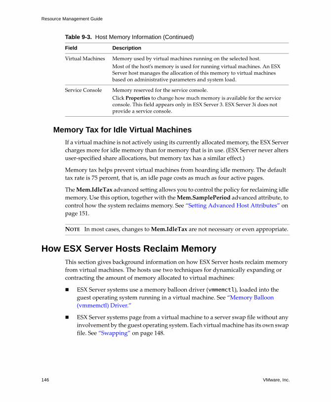
Resource Management Guide
146 VMware, Inc.
Memory Tax for Idle Virtual Machines
If a virtual machine is not actively using its currently allocated memory, the ESX Server
charges more for idle memory than for memory that is in use. (ESX Server never alters
user‐specified share allocations, but memory tax has a similar effect.)
Memory tax helps prevent virtual machines from hoarding idle memory. The default
tax rate is 75 percent, that is, an idle page costs as much as four active pages.
The Mem.IdleTax advanced setting allows you to control the policy for reclaiming idle
memory. Use this option, together with the Mem.SamplePeriod advanced attribute, to
control how the system reclaims memory. See “Setting Advanced Host Attributes” on
page 151.
How ESX Server Hosts Reclaim Memory This section gives background information on how ESX Server hosts reclaim memory
from virtual machines. The hosts use two techniques for dynamically expanding or
contracting the amount of memory allocated to virtual machines:
ESX Server systems use a memory balloon driver (vmmemctl), loaded into the guest operating system running in a virtual machine. See “Memory Balloon
(vmmemctl) Driver.”
ESX Server systems page from a virtual machine to a server swap file without any
involvement by the guest operating system. Each virtual machine has its own swap
file. See “Swapping” on page 148.
Virtual Machines Memory used by virtual machines running on the selected host.
Most of the host’s memory is used for running virtual machines. An ESX Server host manages the allocation of this memory to virtual machines based on administrative parameters and system load.
Service Console Memory reserved for the service console.
Click Properties to change how much memory is available for the service console. This field appears only in ESX Server 3. ESX Server 3i does not provide a service console.
Table 9-3. Host Memory Information (Continued)
Field Description
NOTE In most cases, changes to Mem.IdleTax are not necessary or even appropriate.

VMware, Inc. 147
Chapter 9 Advanced Resource Management
Memory Balloon (vmmemctl) Driver
The vmmemctl driver collaborates with the server to reclaim pages that are considered
least valuable by the guest operating system. The driver uses a proprietary ballooning
technique that provides predictable performance which closely matches the behavior
of a native system under similar memory constraints. This technique increases or
decreases memory pressure on the guest operating system, causing the guest to call its
own native memory management algorithms. When memory is tight, the guest
operating system determines which pages to reclaim and, if necessary, swaps them to
its own virtual disk. See Figure 9‐2.
Figure 9-2. Memory Ballooning in the Guest Operating System
If necessary, you can limit the amount of memory vmmemctl reclaims by setting the
sched.mem.maxmemctl parameter for a specific virtual machine. This option specifies
the maximum amount of memory that can be reclaimed from a virtual machine in
megabytes (MB). See “Setting Advanced Virtual Machine Attributes” on page 155.
NOTE You must configure the guest operating system with sufficient swap space.
Some guest operating systems have additional limitations. See “Swap Space and Guest
Operating Systems” on page 148.
1
2
3
memory
memory
memory
swap space
swap space

Resource Management Guide
148 VMware, Inc.
Swap Space and Guest Operating Systems
If you choose to overcommit memory with ESX Server, you need to be sure your guest
operating systems have sufficient swap space. This swap space must be greater than or
equal to the difference between the virtual machine’s configured memory size and its
Reservation.
To prevent virtual machine failure, increase the size of the swap space in your virtual
machines:
Windows guest operating systems — Windows operating systems refer to their
swap space as paging files. Some Windows operating systems try to increase the
size of paging files, if there is sufficient free disk space.
Refer to your Microsoft Windows documentation or search the Windows help files
for “paging files.” Follow the instructions for changing the size of the virtual
memory paging file.
Linux guest operating system — Linux operating systems refer to their swap
space as swap files. For information on increasing swap files, refer to the following
Linux man pages:
mkswap — Sets up a Linux swap area.
swapon — Enables devices and files for paging and swapping.
Guest operating systems with a lot of memory and small virtual disks (for example, a
virtual machine with 8GB RAM and a 2GB virtual disk) are more susceptible to having
insufficient swap space.
Swapping
A swap file is created by the ESX Server host when a virtual machine is powered on. If
this file cannot be created, the virtual machine cannot power on. By default, the swap
file is created in the same location as the virtual machineʹs configuration file. Instead of
accepting this default, you can also:
Use per‐virtual machine configuration options to change the datastore to another
shared storage location. See Table 9‐7.
Use host‐local swap, which allows you to specify a datastore stored locally on the
host. This allows you to swap at a per‐host level, saving space on the SAN.
However, it can lead to a slight degradation in performance for VMotion.
CAUTION If memory is overcommitted, and the guest operating system is configured
with insufficient swap space, the guest operating system in the virtual machine can fail.

VMware, Inc. 149
Chapter 9 Advanced Resource Management
To enable host-local swap for a cluster
1 Right‐click the cluster in the VI Client inventory panel and click Edit Settings.
2 In the left pane of the cluster Settings dialog box that appears, click Swapfile
Location.
3 Select the Store the swapfile in the datastore specified by the host option and
click OK.
4 Select one of the cluster’s hosts in the VI Client inventory panel and click the
Configuration tab.
5 Select Virtual Machine Swapfile Location.
6 Click the Swapfile Datastore tab and from the list provided select the local
datastore to use and click OK.
7 Repeat Step 4 through Step 6 for each host in the cluster.
To enable host-local swap for a standalone host
1 Select the host in the VI Client inventory panel and click the Configuration tab.
2 Select Virtual Machine Swapfile Location.
3 Under the Swapfile location tab of the Virtual Machine Swapfile Location dialog
box that appears, select the Store the swapfile in the swapfile datastore option.
4 Click the Swapfile Datastore tab, from the list provided select the local datastore
to use and click OK.
ESX Server hosts use swapping to forcibly reclaim memory from a virtual machine
when no vmmemctl driver is available because the vmmemctl driver:
Was never installed
Has been explicitly disabled
Is not running (for example, while the guest operating system is booting)
Is temporarily unable to reclaim memory quickly enough to satisfy current system
demands
Is functioning properly, but maximum balloon size has been reached.

Resource Management Guide
150 VMware, Inc.
Standard demand‐paging techniques swap pages back in when the virtual machine
needs them.
Swap Space and Memory Overcommitment
Swap space must be reserved on an ESX Server host for any unreserved virtual machine
memory, which is the difference between the reservation and the configured memory
size. This swap reservation is required to ensure that the system is able to preserve
virtual machine memory under any circumstances. In practice, only a small fraction of
the swap space might be used.
Swap Files and ESX Server Failure
If an ESX Server system fails, and that system had running virtual machines that were
using swap files, those swap files continue to exist and take up disk space even after the
ESX Server system restarts.
To delete swap files
1 Start the virtual machine again.
2 Stop the virtual machine explicitly.
Sharing Memory Across Virtual MachinesMany ESX Server workloads present opportunities for sharing memory across virtual
machines. For example, several virtual machines might be running instances of the
same guest operating system, have the same applications or components loaded, or
contain common data. In such cases, an ESX Server host uses a proprietary transparent
page sharing technique to securely eliminate redundant copies of memory pages. With
memory sharing, a workload running in virtual machines often consumes less memory
than it would when running on physical machines. As a result, higher levels of
overcommitment can be supported efficiently.
NOTE For optimum performance, ESX Server hosts use the ballooning approach
(implemented by the vmmemctl driver) whenever possible. Swapping is a reliable
mechanism of last resort that a host uses only when necessary to reclaim memory.
NOTE These swap files can consume many gigabytes of disk space so ensure that you
delete them properly.
VMware, Inc. 151
Chapter 9 Advanced Resource Management
Use the Mem.ShareScanTime and Mem.ShareScanGHz advanced settings to control
the rate at which the system scans memory to identify opportunities for sharing
memory.
You can also disable sharing for individual virtual machines by setting the
sched.mem.pshare.enable option to FALSE (this option defaults to TRUE). See
“Setting Advanced Virtual Machine Attributes” on page 155.
ESX Server memory sharing runs as a background activity that scans for sharing
opportunities over time. The amount of memory saved varies over time. For a fairly
constant workload, the amount generally increases slowly until all sharing
opportunities are exploited.
To determine the effectiveness of memory sharing for a given workload, try running the
workload, and use resxtop or esxtop to observe the actual savings. Find the information in the PSHARE field of the interactive mode in the Memory page. See “Using
the Utilities in Interactive Mode” on page 179.
Advanced Attributes and What They DoThis section lists the advanced attributes available for customizing memory
management.
Setting Advanced Host Attributes
(SEE UPDATE) This section guides you through setting advanced attributes for a host and
lists a few attributes you might want to set under certain circumstances.
To set advanced attributes for a host
1 In the VI Client inventory panel, select the virtual machine you want to customize.
2 Choose Edit Settings in the Commands panel and select the Options tab.
3 Select Advanced, and click the Configuration Parameters button.
4 Click Advanced Settings.
CAUTION Using these advanced attributes is appropriate only under special
circumstances. In most cases, changing the basic settings (Reservation, Limit, Shares)
or using the default settings results in an appropriate allocation.

Resource Management Guide
152 VMware, Inc.
5 In the Advanced Settings dialog box select the appropriate item (for example, CPU
or Memory), and scroll in the right panel to find and change the attribute.
Table 9‐5, Table 9‐6, and Table 9‐7 list the advanced resource management attributes
discussed in this document.
CAUTION Setting these attributes is recommended only for advanced users with
experience using ESX Server hosts. In most cases, the default settings produce the
optimum result.
Table 9-4. Advanced CPU Attributes
Attribute Description
CPU.MachineClearThreshold If you are using a host enabled for hyperthreading and set this attribute to 0, quarantining is disabled. See “Quarantining” on page 139.

VMware, Inc. 153
Chapter 9 Advanced Resource Management
Table 9-5. Advanced Memory Attributes
Attribute Description Default
Mem.CtlMaxPercent Limits the maximum amount of memory that can be reclaimed from any virtual machine using vmmemctl, based on a percentage of its configured memory size. Specifying 0 disables reclamation via vmmemctl for all virtual machines.
65
Mem.ShareScanTime Specifies the time, in minutes, within which an entire virtual machine is to be scanned for page sharing opportunities. Defaults to 60 minutes.
60
Mem.ShareScanGHz Specifies the maximum amount of memory pages to scan (per second) for page sharing opportunities for each GHz of available host CPU resource.
Defaults to 4MB/sec per 1GHz
4
Mem.IdleTax Specifies the idle memory tax rate, as a percentage. This tax effectively charges virtual machines more for idle memory than for memory they are actively using. A tax rate of 0 percent defines an allocation policy that ignores working sets and allocates memory strictly based on shares. A high tax rate results in an allocation policy that allows idle memory to be reallocated away from virtual machines that are unproductively hoarding it.
75
Mem.SamplePeriod Specifies the periodic time interval, measured in seconds of the virtual machine’s execution time, over which memory activity is monitored to estimate working set sizes.
60
Mem.BalancePeriod Specifies the periodic time interval, in seconds, for automatic memory reallocations. Reallocations are also triggered by significant changes in the amount of free memory.
15
Mem.AllocGuestLargePage Set this option to 1 to enable backing of guest large pages with host large pages. Reduces TLB misses and improves performance in server workloads that use guest large pages.
1
Mem.AllocUsePSharePool
and
Mem.AllocUseGuestPool
Set these options to 1 to reduce memory fragmentation. If host memory is fragmented, the availability of host large pages is reduced. These options improve the probability of backing guest large pages with host large pages.
1

Resource Management Guide
154 VMware, Inc.
See Chapter 10, “Using NUMA Systems with ESX Server,” on page 157 for additional
information.
Table 9-6. Advanced NUMA Attributes
Attribute Description Default
Numa.RebalanceEnable Set this option to 0 to disable all NUMA rebalancing and initial placement of virtual machines, effectively disabling the NUMA scheduling system.
1
Numa.PageMigEnable If this option is set to 0, the system does not automatically migrate pages between nodes to improve memory locality. Page migration rates set manually are still in effect.
1
Numa.AutoMemAffinity If this option is set to 0, the system does not automatically set memory affinity for virtual machines with CPU affinity set.
1
Numa.MigImbalanceThreshold The NUMA rebalancer computes the CPU imbalance between nodes, taking into account the difference between each virtual machine’s CPU time entitlement and its actual consumption. This option controls the minimum load imbalance between nodes needed to trigger a virtual machine migration, in percent.
10
Numa.RebalancePeriod Controls the frequency of rebalance periods, specified in milliseconds. More frequent rebalancing can increase CPU overheads, particularly on machines with a large number of running virtual machines. More frequent rebalancing can also improve fairness.
2000
Numa.RebalanceCoresTotal Specifies the minimum number of total processor cores on the host required to enable the NUMA rebalancer.
4
Numa.RebalanceCoresNode Specifies the minimum number of processor cores per node required to enable the NUMA rebalancer.
This option and Numa.RebalanceCoresTotal are useful when you want to disable NUMA rebalancing on small NUMA configurations (for example, two‐way Opteron hosts), where the small number of total or per‐node processors can compromise scheduling fairness when NUMA rebalancing is enabled.
2

VMware, Inc. 155
Chapter 9 Advanced Resource Management
Setting Advanced Virtual Machine Attributes
This section takes you through setting advanced attributes for a virtual machine, and
lists the attributes you might want to set.
To set advanced attributes for a virtual machine
1 Select the virtual machine in the VI Client inventory panel, and choose Edit
Settings from the right‐click menu.
2 Click Options and click Advanced>General.
3 Click the Configuration Parameters button.
4 In the dialog box that appears, click Add Row to enter a new parameter and its
value.

Resource Management Guide
156 VMware, Inc.
Set the following advanced attributes for virtual machines.
Table 9-7. Advanced Virtual Machine Attributes
Attribute Description
sched.mem.maxmemctl Maximum amount of memory that can be reclaimed from the selected virtual machine by ballooning, in megabytes (MB). If the ESX Server host needs to reclaim additional memory, it is forced to swap. Swapping is less desirable than ballooning.
sched.mem.pshare.enable Enables memory sharing for a selected virtual machine.
This boolean value defaults to True. If you set it to False for a virtual machine, memory sharing is turned off.
sched.swap.persist Specifies whether the virtual machine’s swap files should persist or be deleted when the virtual machine is powered off. By default, the system creates the swap file for a virtual machine when the virtual machine is powered on, and deletes the swap file when the virtual machine is powered off.
sched.swap.dir VMFS directory where the virtual machineʹs swap file is located. Defaults to the virtual machineʹs working directory, that is, the VMFS directory that contains its configuration file.
sched.swap.file Filename for the virtual machineʹs swap file. By default, the system generates a unique name when it creates the swap file.
CAUTION If you modify the sched.swap.dir attribute for a virtual machine in a DRS
cluster, ensure that every host in the cluster can access the swap file location you specify
or you must disable DRS for that virtual machine.

VMware, Inc. 157
10
ESX Server supports memory access optimization for Intel and AMD Opteron
processors in server architectures that support NUMA (non‐uniform memory access).
This chapter gives background information on NUMA technologies and describes
optimizations available with ESX Server.
This chapter discusses the following topics:
“Introduction to NUMA” on page 158
“ESX Server NUMA Scheduling” on page 159
“VMware NUMA Optimization Algorithms” on page 160
“Manual NUMA Controls” on page 162
“IBM Enterprise X‐Architecture Overview” on page 163
“AMD Opteron‐Based Systems Overview” on page 164
“Obtaining NUMA Configuration Information and Statistics” on page 165
“CPU Affinity for Associating Virtual Machines with a Single NUMA Node” on
page 165
“Memory Affinity for Associating Memory Allocations with a NUMA Node” on
page 166
Using NUMA Systems with ESX Server 10

Resource Management Guide
158 VMware, Inc.
Introduction to NUMANUMA systems are advanced server platforms with more than one system bus. They
can harness large numbers of processors in a single system image with superior price
to performance ratios. The systems that offer a NUMA platform to support
industry‐standard operating systems include those based on either AMD CPUs or the
IBM Enterprise X‐Architecture.
What Is NUMA?
For the past decade, processor clock speed has increased dramatically. A
multi‐gigahertz CPU, however, needs to be supplied with a large amount of memory
bandwidth to use its processing power effectively. Even a single CPU running a
memory‐intensive workload, such as a scientific computing application, can be
constrained by memory bandwidth.
This problem is amplified on symmetric multiprocessing (SMP) systems, where many
processors must compete for bandwidth on the same system bus. Some high‐end
systems often try to solve this problem by building a high‐speed data bus. However,
such a solution is expensive and limited in scalability.
NUMA is an alternative approach that links several small, cost‐effective nodes via a
high‐performance connection. Each node contains processors and memory, much like
a small SMP system. However, an advanced memory controller allows a node to use
memory on all other nodes, creating a single system image. When a processor accesses
memory that does not lie within its own node (remote memory), the data must be
transferred over the NUMA connection, which is slower than accessing local memory.
Memory access times are not uniform and depend on the location of the memory and
the node from which it is accessed, as the technology’s name implies.
NUMA Challenges for Operating Systems
Because a NUMA architecture provides a single system image, it can often run an
operating system with no special optimizations. For example, Windows 2000 is fully
supported on the IBM x440, although it is not designed for use with NUMA.
There are many disadvantages to using such an operating system on a NUMA
platform. The high latency of remote memory accesses can leave the processors
under‐utilized, constantly waiting for data to be transferred to the local node, and the
NUMA connection can become a bottleneck for applications with high‐memory
bandwidth demands.

VMware, Inc. 159
Chapter 10 Using NUMA Systems with ESX Server
Furthermore, performance on such a system can be highly variable. It varies, for
example, if an application has memory located locally on one benchmarking run, but a
subsequent run happens to place all of that memory on a remote node. This
phenomenon can make capacity planning difficult. Finally, processor clocks might not
be synchronized between multiple nodes, so applications that read the clock directly
might behave incorrectly.
Some high‐end UNIX systems provide support for NUMA optimizations in their
compilers and programming libraries. This support requires software developers to
tune and recompile their programs for optimal performance. Optimizations for one
system are not guaranteed to work well on the next generation of the same system.
Other systems have allowed an administrator to explicitly decide on the node on which
an application should run. While this might be acceptable for certain applications that
demand 100 percent of their memory to be local, it creates an administrative burden
and can lead to imbalance between nodes when workloads change.
Ideally, the system software provides transparent NUMA support, so that applications
can benefit immediately without modifications. The system should maximize the use
of local memory and schedule programs intelligently without requiring constant
administrator intervention. Finally, it must respond well to changing conditions
without compromising fairness or performance.
ESX Server NUMA SchedulingESX Server uses a sophisticated NUMA scheduler to dynamically balance processor
load and memory locality or processor load balance, as follows:
1 Each virtual machine managed by the NUMA scheduler is assigned a home
node—one of the system’s NUMA nodes containing processors and local memory,
as indicated by the System Resource Allocation Table (SRAT).
2 When memory is allocated to a virtual machine, the ESX Server host preferentially
allocates it from the home node.
3 The NUMA scheduler can dynamically change a virtual machineʹs home node to
respond to changes in system load. The scheduler might migrate a virtual machine
to a new home node to reduce processor load imbalance. Because this might cause
more of its memory to be remote, the scheduler might migrate the virtual
machine’s memory dynamically to its new home node to improve memory locality.
The NUMA scheduler might also swap virtual machines between nodes when this
improves overall memory locality.
Resource Management Guide
160 VMware, Inc.
Some virtual machines are not managed by the ESX Server NUMA scheduler. For
example, if you manually set the processor affinity for a virtual machine, the NUMA
scheduler might not be able to manage this virtual machine. Virtual machines that have
more virtual processors than the number of physical processor cores available on a
single hardware node cannot be managed automatically. Virtual machines that are not
managed by the NUMA scheduler still run correctly. However, they donʹt benefit from
ESX Serverʹs NUMA optimizations.
The NUMA scheduling and memory placement policies in VMware ESX Server can
manage all virtual machines transparently, so that administrators do not need to
address the complexity of balancing virtual machines between nodes explicitly.
The optimizations work seamlessly regardless of the type of guest operating system.
ESX Server provides NUMA support even to virtual machines that do not support
NUMA hardware, such as Windows NT 4.0. As a result, you can take advantage of new
hardware even with legacy operating systems.
VMware NUMA Optimization AlgorithmsThis section describes the algorithms used by VMware ESX Server to maximize
application performance while still maintaining resource guarantees.
Home Nodes and Initial Placement
When a virtual machine is powered on, ESX Server assigns it a home node. A virtual
machine runs only on processors within its home node, and its newly allocated
memory comes from the home node as well. Unless a virtual machine’s home node
changes, it uses only local memory, avoiding the performance penalties associated with
remote memory accesses to other NUMA nodes.
New virtual machines are initially assigned to home nodes in a round robin fashion,
with the first virtual machine going to the first node, the second virtual machine to the
second node, and so forth. This policy ensures that memory is evenly used throughout
all nodes of the system.
Several operating systems, such as Windows Server 2003, provide this level of NUMA
support, which is known as initial placement. It might be sufficient for systems that run
only a single workload, such as a benchmarking configuration, which does not change
over the course of the system’s uptime. However, initial placement is not sophisticated
enough to guarantee good performance and fairness for a datacenter‐class system that
is expected to support changing workloads.

VMware, Inc. 161
Chapter 10 Using NUMA Systems with ESX Server
To understand the weaknesses of an initial‐placement‐only system, consider the
following example: an administrator starts four virtual machines and the system places
two of them on the first node. The second two virtual machines are placed on the
second node. If both virtual machines on the second node are stopped, or if they
become idle, the system becomes completely imbalanced, with the entire load placed
on the first node. Even if the system allows one of the remaining virtual machines to
run remotely on the second node, it suffers a serious performance penalty because all
its memory remains on its original node.
Dynamic Load Balancing and Page Migration
ESX Server combines the traditional initial placement approach with a dynamic
rebalancing algorithm. Periodically (every two seconds by default), the system
examines the loads of the various nodes and determines if it should rebalance the load
by moving a virtual machine from one node to another. This calculation takes into
account the resource settings for virtual machines and resource pools to improve
performance without violating fairness or resource entitlements.
The rebalancer selects an appropriate virtual machine and changes its home node to the
least loaded node. When it can, the rebalancer moves a virtual machine that already has
some memory located on the destination node. From that point on (unless it is moved
again), the virtual machine allocates memory on its new home node and it runs only on
processors within the new home node.
Rebalancing is an effective solution to maintain fairness and ensure that all nodes are
fully used. The rebalancer might need to move a virtual machine to a node on which it
has allocated little or no memory. In this case, the virtual machine incurs a performance
penalty associated with a large number of remote memory accesses. ESX Server can
eliminate this penalty by transparently migrating memory from the virtual machine’s
original node to its new home node:
1 The system selects a page (4KB of contiguous memory) on the original node and
copies its data to a page in the destination node.
2 The system uses the virtual machine monitor layer and the processor’s memory
management hardware to seamlessly remap the virtual machine’s view of memory,
so that it uses the page on the destination node for all further references,
eliminating the penalty of remote memory access.

Resource Management Guide
162 VMware, Inc.
When a virtual machine moves to a new node, the ESX Server host immediately begins
to migrate its memory in this fashion. It manages the rate to avoid overtaxing the
system, particularly when the virtual machine has little remote memory remaining or
when the destination node has little free memory available. The memory migration
algorithm also ensures that the ESX Server host does not move memory needlessly if a
virtual machine is moved to a new node for only a short period.
When initial placement, dynamic rebalancing, and intelligent memory migration work
in conjunction, they ensure good memory performance on NUMA systems, even in the
presence of changing workloads. When a major workload change occurs, for instance
when new virtual machines are started, the system takes time to readjust, migrating
virtual machines and memory to new locations. After a short period, typically seconds
or minutes, the system completes its readjustments and reaches a steady state.
Transparent Page Sharing Optimized for NUMA
Many ESX Server workloads present opportunities for sharing memory across virtual
machines. For example, several virtual machines might be running instances of the
same guest operating system, have the same applications or components loaded, or
contain common data. In such cases, ESX Server systems use a proprietary transparent
page‐sharing technique to securely eliminate redundant copies of memory pages. With
memory sharing, a workload running in virtual machines often consumes less memory
than it would when running on physical machines. As a result, higher levels of
overcommitment can be supported efficiently.
Transparent page sharing for ESX Server systems has also been optimized for use on
NUMA systems. On NUMA systems, pages are shared per‐node, so each NUMA node
has its own local copy of heavily shared pages. When virtual machines use shared
pages, they donʹt need to access remote memory.
Manual NUMA ControlsIf you have applications that use a lot of memory or have a small number of virtual
machines, you might want to optimize performance by specifying virtual machine CPU
and memory placement explicitly. This is useful if a virtual machine runs a
memory‐intensive workload, such as an in‐memory database or a scientific computing
application with a large data set. You might also want to optimize NUMA placements
manually if the system workload is known to be simple and unchanging. For example,
an eight‐processor system running eight virtual machines with similar workloads is
easy to optimize explicitly.
NOTE In most situations, an ESX Server host’s automatic NUMA optimizations result
in good performance.

VMware, Inc. 163
Chapter 10 Using NUMA Systems with ESX Server
ESX Server provides two sets of controls for NUMA placement, so that administrators
can control memory and processor placement of a virtual machine.
The VI Client allows you to specify:
CPU Affinity—A virtual machine should use only the processors on a given node.
See “CPU Affinity for Associating Virtual Machines with a Single NUMA Node”
on page 165.
Memory Affinity—The server should allocate memory only on the specified node.
See “Memory Affinity for Associating Memory Allocations with a NUMA Node”
on page 166.
If both options are set before a virtual machine starts, the virtual machine runs only on
the selected node and all of its memory is allocated locally.
An administrator can also manually move a virtual machine to another node after the
virtual machine has started running. In this case, the page migration rate of the virtual
machine should also be set manually, so that memory from the virtual machine’s
previous node can be moved to its new node.
Manual NUMA placement might interfere with the ESX Server resource management
algorithms, which attempt to give each virtual machine a fair share of the system’s
processor resources. For example, if ten virtual machines with processor‐intensive
workloads are manually placed on one node, and only two virtual machines are
manually placed on another node, it is impossible for the system to give all twelve
virtual machines equal shares of the system’s resources. You must consider these issues
when making manual NUMA placement decisions.
IBM Enterprise X-Architecture OverviewThe IBM Enterprise X‐Architecture supports servers with up to four nodes (also called
CECs or SMP Expansion Complexes in IBM terminology). Each node may contain up
to four Intel Xeon MP processors for a total of 16 CPUs. The next generation IBM
eServer x445 uses an enhanced version of the Enterprise X‐Architecture, and scales to
eight nodes with up to four Xeon MP processors for a total of 32 CPUs. The
third‐generation IBM eServer x460 provides similar scalability but also supports 64‐bit
Xeon MP processors. The high scalability of all these systems stems from the Enterprise
X‐Architecture’s NUMA design that is shared with IBM high end POWER4‐based
pSeries servers. See the IBM Redbook IBM eServer xSeries 440 Planning and Installation
Guide for a more detailed description of the Enterprise X Architecture.

Resource Management Guide
164 VMware, Inc.
AMD Opteron-Based Systems OverviewAMD Opteron‐based systems, such as the HP ProLiant DL585 Server, also provide
NUMA support. The BIOS setting for node interleaving determines whether the system
behaves more like a NUMA system or more like a Uniform Memory Architecture
(UMA) system. See the HP ProLiant DL585 Server Technology technology brief. See
also the HP ROM‐Based Setup Utility User Guide at the HP Web site.
By default, node interleaving is disabled, so each processor has its own memory. The
BIOS builds a System Resource Allocation Table (SRAT), so the ESX Server host detects
the system as NUMA and applies NUMA optimizations. If you enable node
interleaving (also known as interleaved memory), the BIOS does not build an SRAT, so
the ESX Server host does not detect the system as NUMA.
Currently shipping Opteron processors have up to four cores per socket. When node
memory is enabled, the memory on the Opteron processors is divided such that each
socket has some local memory, but memory for other sockets is remote. The single‐core
Opteron systems have a single processor per NUMA node and the dual‐core Opteron
systems have two processors for each NUMA node.
SMP virtual machines (having two virtual processors) cannot reside within a NUMA
node that has a single core, such as the single‐core Opteron processors. This also means
they cannot be managed by the ESX Server NUMA scheduler. Virtual machines that are
not managed by the NUMA scheduler still run correctly. However, those virtual
machines donʹt benefit from the ESX Server NUMA optimizations. Uniprocessor
virtual machines (with a single virtual processor) can reside within a single NUMA
node and are managed by the ESX Server NUMA scheduler.
NOTE For small Opteron systems, NUMA rebalancing is now disabled by default to
ensure scheduling fairness. Use the Numa.RebalanceCoresTotal and
Numa.RebalanceCoresNode options to change this behavior. See “Setting Advanced
Virtual Machine Attributes” on page 155.

VMware, Inc. 165
Chapter 10 Using NUMA Systems with ESX Server
Obtaining NUMA Configuration Information and StatisticsNUMA configuration information and statistics can be viewed in the Memory panel of
the resxtop (or esxtop) utility. See “Memory Panel” on page 185.
CPU Affinity for Associating Virtual Machines with a Single NUMA Node
You might be able to improve the performance of the applications on a virtual machine
by associating it to the CPU numbers on a single NUMA node (manual CPU affinity).
To set CPU affinity for a single NUMA node
1 Using a VI Client, right‐click a virtual machine and choose Edit Settings.
2 In the Virtual Machine Properties dialog box, select the Resources tab and choose
Advanced CPU.
3 In the Scheduling Affinity panel, set CPU affinity for different NUMA nodes.
CAUTION There are a number of potential issues if you use CPU affinity. See “Potential
Issues with Affinity” on page 133.
NOTE You must manually select the boxes for all processors in the NUMA node.
CPU affinity is specified on a per‐processor, not on a per‐node, basis.
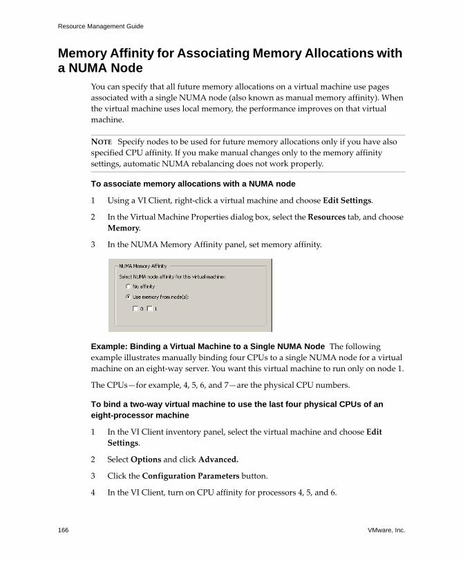
Resource Management Guide
166 VMware, Inc.
Memory Affinity for Associating Memory Allocations with a NUMA Node
You can specify that all future memory allocations on a virtual machine use pages
associated with a single NUMA node (also known as manual memory affinity). When
the virtual machine uses local memory, the performance improves on that virtual
machine.
To associate memory allocations with a NUMA node
1 Using a VI Client, right‐click a virtual machine and choose Edit Settings.
2 In the Virtual Machine Properties dialog box, select the Resources tab, and choose
Memory.
3 In the NUMA Memory Affinity panel, set memory affinity.
Example: Binding a Virtual Machine to a Single NUMA Node The following
example illustrates manually binding four CPUs to a single NUMA node for a virtual
machine on an eight‐way server. You want this virtual machine to run only on node 1.
The CPUs—for example, 4, 5, 6, and 7—are the physical CPU numbers.
To bind a two-way virtual machine to use the last four physical CPUs of an eight-processor machine
1 In the VI Client inventory panel, select the virtual machine and choose Edit
Settings.
2 Select Options and click Advanced.
3 Click the Configuration Parameters button.
4 In the VI Client, turn on CPU affinity for processors 4, 5, and 6.
NOTE Specify nodes to be used for future memory allocations only if you have also
specified CPU affinity. If you make manual changes only to the memory affinity
settings, automatic NUMA rebalancing does not work properly.
VMware, Inc. 167
Chapter 10 Using NUMA Systems with ESX Server
To set the virtual machine’s memory to specify that all of the virtual machine’s memory should be allocated on node 1
1 In the VI Client inventory panel, select the virtual machine and choose Edit
Settings.
2 Select Options and click Advanced.
3 Click the Configuration Parameters button.
4 In the VI Client, set memory affinity for the NUMA node to 1.
Completing these two tasks ensures that the virtual machine runs only on NUMA
node 1 and, when possible, allocates memory from the same node.

Resource Management Guide
168 VMware, Inc.

VMware, Inc. 169
11
This chapter discusses some best practices for users of ESX Server and VirtualCenter.
This chapter discusses the following topics:
“Resource Management Best Practices” on page 169
“Creating and Deploying Virtual Machines” on page 170
“VMware HA Best Practices” on page 172
Resource Management Best PracticesThe following guidelines can help you achieve optimal performance for your virtual
machines:
If you expect frequent changes to the total available resources, use Shares to
allocate resources fairly across virtual machines. If you use Shares, and you
upgrade the host, for example, each virtual machine stays at the same priority
(keeps the same number of shares) even though each share represents a larger
amount of memory or CPU.
Use Reservation to specify the minimum acceptable amount of CPU or memory,
not the amount you want to have available. The host assigns additional resources
as available based on the number of shares and the limit for your virtual machine.
The amount of concrete resources represented by a reservation does not change
when you change the environment, such as by adding or removing virtual
machines.
Do not set Reservation too high. A reservation that is too high can limit the number
of virtual machines in a resource pool.
Best Practices 11

Resource Management Guide
170 VMware, Inc.
When specifying the reservations for virtual machines, do not commit all
resources. As you move closer to fully reserving all capacity in the system, it
becomes increasingly difficult to make changes to reservations and to the resource
pool hierarchy without violating admission control. In a DRS‐enabled cluster,
reservations that fully commit the capacity of the cluster or of individual hosts in
the cluster can prevent DRS from migrating virtual machines between hosts.
Use resource pools for delegated resource management. To fully isolate a resource
pool, make the resource pool type Fixed and use Reservation and Limit.
Group virtual machines for a multitier service in a resource pool. Resource pools
allow the ESX Server host to assign resources for the service as a whole.
Creating and Deploying Virtual MachinesThis section gives best practices information for planning and creating virtual
machines.
Planning
Before you deploy a virtual machine, you need to:
Plan your load mix.
Understand goals and expectations.
Understand the requirements, and what it means to be successful.
Avoid mixing virtual machines that have competing resource requirements.
Test before you deploy if you have specific performance expectations,.
Virtualization allows a number of virtual machines to share the host’s resources. It does
not create new resources. Virtualization can result in overheads.
Creating Virtual Machines
When you create virtual machines, be sure to size them according to your actual needs,
just like physical machines. Overconfigured virtual machines waste shareable
resources.
To optimize performance, disable unused virtual devices such as COM ports, LPT
ports, floppy drives, CD‐ROMs, USB adapters, and so on. Those devices are
periodically polled by the guest operating system even if they are not in use. This
unproductive polling wastes shareable resources.
VMware, Inc. 171
Chapter 11 Best Practices
Install VMware Tools, which helps you achieve higher performance, can result in more
efficient CPU utilization, and includes disk, network, and memory reclamation drivers.
Deploying the Guest Operating System
Tune and size the virtual machine operating system just as you tune the operating
system of a physical machine with registry, swap space, and so on. Disable unnecessary
programs and services such as screen savers. Unnecessary programs and services waste
shareable resources.
Keep the guest operating system up‐to‐date with the latest patches. If you are using
Microsoft Windows as the guest operating system, check for any known operating
system issues in Microsoft knowledge base articles.
Deploying Guest Applications
Tune and size applications on your virtual machines in the same way you tune and size
applications on your physical machine.
Do not run single‐threaded applications in an SMP virtual machine. Single‐threaded
workloads cannot take advantage of additional virtual CPUs, and unused virtual CPUs
waste shareable resources. However, a workload consisting of several single‐threaded
applications running concurrently might be able to take advantage of additional
virtual CPUs.
Configuring VMkernel Memory
VMkernel reclaims memory by ballooning and swapping. See Chapter 9, “Advanced
Resource Management,” on page 129. To use memory resources optimally, avoid high
reclamation activity by correctly sizing virtual machines and by avoiding high memory
overcommitment. See “Memory Overcommitment” on page 42.
VMkernel implements a NUMA scheduler, which supports IBM and AMD NUMA
architectures. The scheduler locates virtual machine memory and virtual CPUs on the
same NUMA node. This prevents possible performance degradation because of remote
memory accesses. The host hardware should be configured so that physical host
memory is evenly balanced across NUMA nodes. See Chapter 10, “Using NUMA
Systems with ESX Server,” on page 157.
NOTE You must configure the guest operating system with sufficient swap space.
Some guest operating systems have additional limitations. See “Swap Space and Guest
Operating Systems” on page 148.

Resource Management Guide
172 VMware, Inc.
VMware HA Best Practices
Use the following VMware HA best practices that are applicable for your ESX Server
implementation and networking architecture.
Networking Best Practices
The configuration of ESX Server host networking and name resolution, as well as the
networking infrastructure external to ESX Server hosts (switches, routers, and
firewalls) is critical to optimizing VMware HA setup. When you configure these
components, use the following best practices to improve VMware HA performance.
If your switches support the PortFast (or an equivalent) setting, enable it on the
physical network switches that connect servers. This helps avoid spanning tree
isolation events. For more information on this option, see the documentation
provided by your networking switch vendor.
Make sure that the following firewall ports are open for communication by the
service console for all ESX Server 3 hosts:
Incoming port: TCP/UDP 8042‐8045
Outgoing port: TCP/UDP 2050‐2250
For better heartbeat reliability, configure end‐to‐end dual network paths between
servers for service console networking. Configure shorter network paths between
the servers in a cluster. Routes with too many hops can cause networking packet
delays for heartbeats.
Disable VMware HA (using VirtualCenter, clear the Enable VMware HA
checkbox in the Settings dialog box for the cluster) when you perform any
networking maintenance that might disable all heartbeat paths between hosts.
(SEE UPDATE) Use DNS for name resolution rather than the error‐prone method of
manually editing the local /etc/hosts file on ESX Server hosts. If you do edit
/etc/hosts, you must include both long and short names.
Use consistent port names on VLANs for public networks. Port names are used to
reconfigure access to the network by virtual machines. If you use inconsistent
names between the original server and the failover server, virtual machines are
disconnected from their networks after failover.
Use valid virtual machine network labels on all servers in a VMware HA cluster.
Virtual machines use these labels to reestablish network connectivity upon restart.

VMware, Inc. 173
Chapter 11 Best Practices
Setting Up Networking Redundancy
Networking redundancy between cluster nodes is important for VMware HA
reliability. Redundant service console networking on ESX Server 3 (or VMkernel
networking on ESX Server 3i) allows the reliable detection of failures and prevents
isolation conditions from occurring, since heartbeats can be sent over multiple
networks.
You can implement network redundancy at the NIC level or at the service
console/VMkernel port level. In most implementations, NIC teaming provides
sufficient redundancy, but you can use or add service console/port redundancy if
additional redundancy is required.
NIC Teaming
As shown in Figure 11‐1, using a team of two NICs connected to separate physical
switches improves the reliability of a service console (or, in ESX Server 3i, VMkernel)
network. Because servers connected through two NICs (and through separate switches)
have two independent paths for sending and receiving heartbeats, the cluster is more
resilient.
To configure a NIC team for the service console, configure the vNICs in vSwitch
configuration for Active/standby configuration. The recommended parameter settings
for the vNICs are:
Default load balancing = route based on originating port ID
Failback = No
NOTE After you have added a NIC to a host in your VMware HA cluster, you must
reconfigure HA on that host.

Resource Management Guide
174 VMware, Inc.
Figure 11-1. Service Console Redundancy Using NIC Teaming
NIC Teaming Scenario The following scenario illustrates the use of a single service
console network with NIC teaming for network redundancy:
You assume some risk when you configure hosts in the cluster with only one
service console network (subnet 10.20.XX.XX). Use two teamed NICs to protect
against NIC failure.
The default timeout is increased to 60 seconds (das.failuredetectiontime = 60000).
Secondary Service Console Network
As an alternative to NIC teaming for providing redundancy for heartbeats, you can
create a secondary service console (or VMkernel port for ESX Server 3i), which is then
attached to a separate virtual switch. The primary service console is still used for
network and management purposes. When the secondary service console network is
created, VMware HA sends heartbeats over both the primary and secondary service
consoles. If one path fails, VMware HA can still send and receive heartbeats over the
other path.
By default, the gateway IP address specified in each ESX Server hostʹs service console
network configuration is used as the isolation address. Each service console network
must have one isolation address it can reach. When you set up service console
redundancy, you must specify an additional host isolation response address
(das.isolationaddress2) for the secondary service console network. This isolation
address should have as few network hops as possible. When you specify a secondary
isolation address, VMware recommends that you increase the
das.failuredetectiontime setting to 20000 milliseconds or greater. See “Setting
Advanced HA Options” on page 126.

VMware, Inc. 175
Chapter 11 Best Practices
You can further optimize your network (if you have already configured a VMotion
network) by adding a secondary service console network to the VMotion vswitch. As shown in Figure 11‐2, a virtual switch can be shared between VMotion networks and a
secondary service console network.
Figure 11-2. Network Redundancy with a Secondary Service Console
Redundant Service Console Network Scenario The following scenario illustrates
the use of a redundant service console network:
Configure each host in the cluster with two service console networks by leveraging
an existing VMotion network (subnets 10.20.YY.YY and 192.168.ZZ.ZZ).
Use the default gateway for the first network and specify
das.isolationaddress2 = 192.168.1.103 as the additional isolation address for the second network.
Increase the default timeout to 20 seconds (das.failuredetectiontime = 20000).

Resource Management Guide
176 VMware, Inc.
Other VMware HA Cluster Considerations
Other considerations for optimizing the performance of your VMware HA cluster
include:
Use larger groups of homogenous servers to allow higher levels of utilization
across an VMware HA‐enabled cluster (on average).
More nodes per cluster can tolerate multiple host failures while still
guaranteeing failover capacities.
Admission control heuristics are conservatively weighted, so that large
servers with many virtual machines can fail over to smaller servers.
To define the sizing estimates used for admission control, set reasonable
reservations for the minimum resources needed.
Admission control will exceed failover capacities when reservations are not
set; otherwise VMware HA will use the largest reservation specified as the
“slot” size (see “Planning for HA Clusters” on page 75.)
At a minimum, set reservations for a few virtual machines considered
average.
Perform your own capacity planning by choosing Allow virtual machines to be
powered on even if they violate availability constraints. Admission control may
be too conservative when host and virtual machine sizes vary widely. VMware HA
still tries to restart as many virtual machines as it can.
VMware, Inc. 177
A
The resxtop and esxtop command‐line utilities provide a detailed look at how
ESX Server uses resources in real time. You can start either utility in one of three modes:
interactive (default), batch, or replay. This appendix explains how to use resxtop and esxtop in each of these modes and give references to available commands and display
statistics. Unless specified otherwise, the commands and statistics for the utilities are
the same. The following topics are discussed:
“Deciding to Use resxtop or esxtop” on page 177
“Using the Utilities in Interactive Mode” on page 179
“Using the Utilities in Batch Mode” on page 200
“Using the Utilities in Replay Mode” on page 201
Deciding to Use resxtop or esxtopThe fundamental difference between resxtop and esxtop is that you can use resxtop remotely (or locally), whereas esxtop can be started only through the service console of a local ESX Server host.
Using the resxtop Utility
The resxtop utility is a Remote Command Line Interface (Remote CLI) command and
before you can use any Remote CLI commands, you must download, install, and
configure the Remote CLI virtual appliance. See the ESX Server 3i version 3.5
Configuration Guide.
Appendix: Performance Monitoring Utilities: resxtop and esxtop
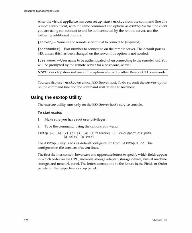
Resource Management Guide
178 VMware, Inc.
After the virtual appliance has been set up, start resxtop from the command line of a
remote Linux client, with the same command line options as esxtop. So that the client you are using can connect to and be authenticated by the remote server, use the
following additional options:
[server]—Name of the remote server host to connect to (required).
[portnumber]—Port number to connect to on the remote server. The default port is
443, unless this has been changed on the server, this option is not needed.
[username]—User name to be authenticated when connecting to the remote host. You
will be prompted by the remote server for a password, as well.
You can also use resxtop on a local ESX Server host. To do so, omit the server option on the command line and the command will default to localhost.
Using the esxtop Utility
The esxtop utility runs only on the ESX Server host’s service console.
To start esxtop
1 Make sure you have root user privileges.
2 Type the command, using the options you want:
esxtop [-] [h] [v] [b] [s] [a] [c filename] [R vm-support_dir_path] [d delay] [n iter]
The esxtop utility reads its default configuration from .esxtop310rc. This configuration file consists of seven lines.
The first six lines contain lowercase and uppercase letters to specify which fields appear
in which order on the CPU, memory, storage adapter, storage device, virtual machine
storage, and network panel. The letters correspond to the letters in the Fields or Order
panels for the respective esxtop panel.
NOTE resxtop does not use all the options shared by other Remote CLI commands.

VMware, Inc. 179
Appendix: Performance Monitoring Utilities: resxtop and esxtop
The seventh line contains information on the other options. Most important, if you
saved a configuration in secure mode, you do not get an insecure esxtop without
removing the s from the seventh line of your .esxtop310rc file. A number specifies
the delay time between updates. As in interactive mode, typing c, m, d, u, v, or n determines the panel with which esxtop starts.
Using the Utilities in Interactive ModeBy default, resxtop and esxtop run in interactive mode. Interactive mode displays
statistics in different panels.
A help menu is available for each panel.
Interactive Mode Command-Line Options
The command‐line options listed in Table A‐1 are available in interactive mode.
NOTE Editing this file is not recommended. Instead, select the fields and the order in
a running esxtop process, make changes, and save this file using the W interactive
command.
Table A-1. Interactive Mode Command-Line Options
Option Description
h Prints help for resxtop (or esxtop) command‐line options.
v Prints resxtop (or esxtop) version number.
s Calls resxtop (or esxtop) in secure mode. In secure mode, the -d command, which specifies delay between updates, is disabled.
d Specifies the delay between updates. The default is five seconds. The minimum is two seconds. Change this with the interactive command s. If you specify a delay of less than two seconds, the delay is set to two seconds.
n Number of iterations. Updates the display n times and exits.
server The name of the remote server host to connect to (required for resxtop only).
portnumber The port number to connect to on the remote server. The default port is 443, and unless this has been changed on the server, this option is not needed. (resxtop only)
username The user name to be authenticated when connecting to the remote host. You are prompted by the remote server for a password, as well (resxtop only).

Resource Management Guide
180 VMware, Inc.
Common Statistics Description
Several statistics appear on the different panels while resxtop (or esxtop) is running in interactive mode. The following statistics are common across all four panels.
The Uptime line, found at the top of each of the four resxtop (or esxtop) panels, displays the current time, time since last reboot, number of currently running worlds
and load averages. A world is an ESX Server VMkernel schedulable entity, similar to a
process or thread in other operating systems.
Below that the load averages over the past one, five, and fifteen minutes appear. Load
averages take into account both running and ready‐to‐run worlds. A load average of
1.00 means that all the physical CPUs are fully utilized. A load average of 2.00 means
that the ESX Server system might need twice as many physical CPUs as are currently
available. Similarly, a load average of 0.50 means that the physical CPUs on the
ESX Server system are half utilized.
Interactive Mode Single-Key Commands
When running in interactive mode, resxtop (or esxtop) recognizes several single‐key commands. Commands listed in Table A‐2 are recognized in all four panels. The
command to specify the delay between updates is disabled if the s option has been given on the command line (see “Interactive Mode Command‐Line Options” on
page 179). All sorting interactive commands sort in descending order.
a Show all statistics. This option overrides configuration file setups and shows all statistics. The configuration file can be the default ~/.esxtop310rc configuration file or a user‐defined configuration file.
c <filename> Load a user‐defined configuration file. If the ‐c option is not used, the default configuration file name is ~/.esxtop310rc. Create your own configuration file, specifying a different file name, using the W single‐key interactive command. See “Interactive Mode Single‐Key Commands” on page 180 for information about W.
Table A-2. Interactive Mode Single-Key Commands
Key Description
h or ? Displays a help menu for the current panel, giving a brief summary of commands, and the status of secure mode.
space Immediately updates the current panel.
^L Erases and redraws the current panel.
Table A-1. Interactive Mode Command-Line Options (Continued)
Option Description
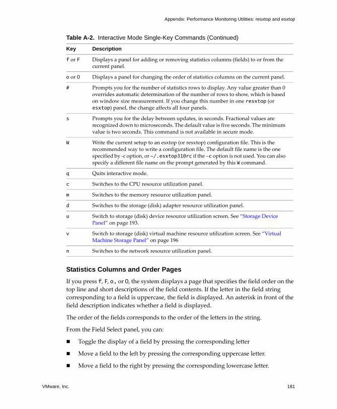
VMware, Inc. 181
Appendix: Performance Monitoring Utilities: resxtop and esxtop
Statistics Columns and Order Pages
If you press f, F, o, or O, the system displays a page that specifies the field order on the top line and short descriptions of the field contents. If the letter in the field string
corresponding to a field is uppercase, the field is displayed. An asterisk in front of the
field description indicates whether a field is displayed.
The order of the fields corresponds to the order of the letters in the string.
From the Field Select panel, you can:
Toggle the display of a field by pressing the corresponding letter
Move a field to the left by pressing the corresponding uppercase letter.
Move a field to the right by pressing the corresponding lowercase letter.
f or F Displays a panel for adding or removing statistics columns (fields) to or from the current panel.
o or O Displays a panel for changing the order of statistics columns on the current panel.
# Prompts you for the number of statistics rows to display. Any value greater than 0 overrides automatic determination of the number of rows to show, which is based on window size measurement. If you change this number in one resxtop (or esxtop) panel, the change affects all four panels.
s Prompts you for the delay between updates, in seconds. Fractional values are recognized down to microseconds. The default value is five seconds. The minimum value is two seconds. This command is not available in secure mode.
W Write the current setup to an esxtop (or resxtop) configuration file. This is the recommended way to write a configuration file. The default file name is the one specified by ‐c option, or ~/.esxtop310rc if the -c option is not used. You can also specify a different file name on the prompt generated by this W command.
q Quits interactive mode.
c Switches to the CPU resource utilization panel.
m Switches to the memory resource utilization panel.
d Switches to the storage (disk) adapter resource utilization panel.
u Switch to storage (disk) device resource utilization screen. See “Storage Device Panel” on page 193.
v Switch to storage (disk) virtual machine resource utilization screen. See “Virtual Machine Storage Panel” on page 196
n Switches to the network resource utilization panel.
Table A-2. Interactive Mode Single-Key Commands (Continued)
Key Description

Resource Management Guide
182 VMware, Inc.
Figure A‐1 shows a field order change.
Figure A-1. Field Order Change
CPU Panel
The CPU panel displays server‐wide statistics as well as statistics for individual world,
resource pool, and virtual machine CPU utilization. Resource pools, running virtual
machines, or other worlds are at times referred to as groups. For worlds belonging to a
virtual machine, statistics for the running virtual machine are displayed. All other
worlds are logically aggregated into the resource pools that contain them.
Figure A-2. CPU Panel
You can change the display using single‐key commands. Statistics and single‐key
commands are discussed in Table A‐3 and Table A‐4.

VMware, Inc. 183
Appendix: Performance Monitoring Utilities: resxtop and esxtop
Table A-3. CPU Panel Statistics
Line Description
PCPU(%) Percentage of CPU utilization per physical CPU and total average physical CPU utilization.
LCPU(%) Percentage of CPU utilization per logical CPU. The percentages for the logical CPUs belonging to a package add up to 100 percent. This line appears only if hyperthreading is present and enabled. See “Hyperthreading and ESX Server” on page 136.
CCPU(%) Percentages of total CPU time as reported by the ESX Server service console.
us — Percentage user time.
sy — Percentage system time.
id — Percentage idle time.
wa — Percentage wait time.
cs/sec — Context switches per second recorded by the service console.
ID Resource pool ID or virtual machine ID of the running world’s resource pool or virtual machine, or world ID of running world.
GID Resource pool ID of the running world’s resource pool or virtual machine.
NAME Name of running world’s resource pool or virtual machine, or name of running world.
NWLD Number of members in running world’s resource pool or virtual machine. If a Group is expanded using the interactive command e (see interactive commands), then NWLD for all the resulting worlds is 1 (some resource pools like the console resource pool have only one member).
%STATE TIMES
Set of CPU statistics made up of the following percentages. For a world, the percentages are a percentage of one physical CPU.
%USED Percentage physical CPU used by the resource pool, virtual machine, or world.
%SYS Percentage of time spent in the ESX Server VMkernel on behalf of the resource pool, virtual machine, or world to process interrupts and to perform other system activities. This time is part of the time used to calculate %USED, above.
%WAIT Percentage of time the resource pool, virtual machine, or world spent in the blocked or busy wait state. This percentage includes the percentage of time the resource pool, virtual machine, or world was idle.
%IDLE (SEE UPDATE) Percentage of time the resource pool, virtual machine, or world was idle. Subtract this percentage from %WAIT, above to see the percentage of time the resource pool, virtual machine, or world was waiting for some event.
%RDY Percentage of time the resource pool, virtual machine, or world was ready to run.

Resource Management Guide
184 VMware, Inc.
%MLMTD Percentage of time the ESX Server VMkernel deliberately did not run the resource pool, virtual machine, or world because doing so would violate the resource pool, virtual machine, or worldʹs limit setting. Even though the resource pool, virtual machine, or world is ready to run when it is prevented from running in this way, the %MLMTD time is not included in %RDY time.
EVENT COUNTS/s
Set of CPU statistics made up of per second event rates. These statistics are for VMware internal use only.
CPU ALLOC Set of CPU statistics made up of the following CPU allocation configuration parameters.
AMIN Resource pool, virtual machine, or world attribute Reservation. See “Creating and Customizing Resource Pools” on page 25.
AMAX Resource pool, virtual machine, or world attribute Limit. A value of ‐1 means unlimited. See “Creating and Customizing Resource Pools” on page 25.
ASHRS Resource pool, virtual machine, or world attribute Shares. See “Creating and Customizing Resource Pools” on page 25.
SUMMARY STATS
Set of CPU statistics made up of the following CPU configuration parameters and statistics. These statistics are applicable only to worlds and not to virtual machines or resource pools.
AFFINITY BIT MASK
Bit mask showing the current scheduling affinity for the world. See “Using CPU Affinity to Assign Virtual Machines to Specific Processors” on page 132.
HTSHARING Current hyperthreading configuration. See “Advanced Server Configuration for Hyperthreading” on page 137.
CPU The physical or logical processor on which the world was running when resxtop (or esxtop) obtained this information.
HTQ Indicates whether the world is currently quarantined or not. N means no and Y means yes. See “Quarantining” on page 139.
TIMER/s Timer rate for this world.
%OVRLP Percentage of system time spent during scheduling of a resource pool, virtual machine, or world on behalf of a different resource pool, virtual machine, or world while the resource pool, virtual machine, or world was scheduled. This time is not included in %SYS. For example, if virtual machine A is currently being scheduled and a network packet for virtual machine B is processed by the ESX Server VMkernel, the time spent appears as %OVRLP for virtual machine A and %SYS for virtual machine B.
Table A-3. CPU Panel Statistics (Continued)
Line Description

VMware, Inc. 185
Appendix: Performance Monitoring Utilities: resxtop and esxtop
Memory Panel
The Memory panel displays server‐wide and group memory utilization statistics. As on
the CPU panel, groups correspond to resource pools, running virtual machines, or
other worlds that are consuming memory. For distinctions between machine memory
and physical memory see “Memory Virtualization” on page 139.
The first line, found at the top of the Memory panel (see Figure A‐3) displays the
current time, time since last reboot, number of currently running worlds, and memory
overcommitment averages. The memory overcommitment averages over the past one,
five, and fifteen minutes appear. Memory overcommitment of 1.00 means a memory
overcommit of 100 percent. See “Memory Overcommitment” on page 42.
%RUN Percentage of total time scheduled. This time does not account for hyperthreading and system time. On a hyperthreading enabled server, the %RUN can be twice as large as %USED.
%CSTP Percentage of time a resource pool spends in a ready, co‐deschedule state.
(Note: you might see this statistic displayed, but it is intended for VMware use only).
Table A-4. CPU Panel Single-Key Commands
Command Description
e Toggles whether CPU statistics are displayed expanded or unexpanded.
The expanded display includes CPU resource utilization statistics broken down by individual worlds belonging to a resource pool or virtual machine. All percentages for the individual worlds are percentage of a single physical CPU.
Consider these example:
If the %Used by a resource pool is 30% on a two‐way server, the resource pool is utilizing 30 percent of two physical CPUs.
If the %Used by a world belonging to a resource pool is 30 percent on a two‐way server, that world is utilizing 30% of one physical CPU.
U Sort resource pools, virtual machines, and worlds by the resource pool’s or virtual machine’s %Used column.
R Sort resource pools, virtual machines, and worlds by the resource pool’s or virtual machine’s %RDY column.
N Sort resource pools, virtual machines, and worlds by the GID column. This is the default sort order.
V Display virtual machine instances only.
Table A-3. CPU Panel Statistics (Continued)
Line Description

Resource Management Guide
186 VMware, Inc.
Figure A-3. Memory Panel
.
Table A-5. Memory Panel Statistics
Field Description
PMEM (MB) Displays the machine memory statistics for the server. All numbers are in megabytes.
total — Total amount of machine memory in the server.
cos — Amount of machine memory allocated to the ESX Server service console (ESX Server 3 only).
vmk — Amount of machine memory being used by the ESX Server VMkernel.
other — Amount of machine memory being used by everything other than the ESX service console (ESX Server 3 only) and ESX Server VMkernel.
free — Amount of machine memory that is free.
VMKMEM (MB)
Displays the machine memory statistics for the ESX Server VMkernel. All numbers are in megabytes.
managed — Total amount of machine memory managed by the ESX Server VMkernel.
min free — Minimum amount of machine memory that the ESX Server VMkernel aims to keep free.
rsvd — Total amount of machine memory currently reserved by resource pools.
ursvd — Total amount of machine memory currently unreserved.
state — Current machine memory availability state. Possible values are high, soft, hard and low. High means that the machine memory is not under any pressure and low means that it is.
COSMEM (MB)
Displays the memory statistics as reported by the ESX Server service console (ESX Server 3 only). All numbers are in megabytes.
free — Amount of idle memory.
swap_t — Total swap configured.
swap_f — Amount of swap free.
r/s is — Rate at which memory is swapped in from disk.
w/s — Rate at which memory is swapped to disk.

VMware, Inc. 187
Appendix: Performance Monitoring Utilities: resxtop and esxtop
NUMA (MB) Displays the ESX Server NUMA statistics. This line appears only if the ESX Server host is running on a NUMA server. All numbers are in megabytes.
For each NUMA node in the server, two statistics are displayed:
The total amount of machine memory in the NUMA node that is managed by the ESX Server.
The amount of machine memory in the node that is currently free (in parentheses).
PSHARE (MB)
Displays the ESX Server page‐sharing statistics. All numbers are in megabytes.
shared — Amount of physical memory that is being shared.
common — Amount of machine memory that is common across worlds.
saving — Amount of machine memory that is saved because of page sharing.
SWAP (MB) Displays the ESX Server swap usage statistics. All numbers are in megabytes.
curr — Current swap usage
target — Where the ESX Server system expects the swap usage to be.
r/s — Rate at which memory is swapped in by the ESX Server system from disk.
w/s — Rate at which memory is swapped to disk by the ESX Server system.
See “Swapping” on page 148 for background information.
MEMCTL (MB)
Displays the memory balloon statistics. All numbers are in megabytes.
curr — Total amount of physical memory reclaimed using the vmmemctl module.
target — Total amount of physical memory the ESX Server host attempts to reclaim using the vmmemctl module.
max — Maximum amount of physical memory the ESX Server host can reclaim using the vmmemctl module.
See “Memory Balloon (vmmemctl) Driver” on page 147.
AMIN Memory reservation for this resource pool or virtual machine. See “Reservation” on page 21.
AMAX Memory limit for this resource pool or virtual machine. A value of ‐1 means Unlimited. See “Limit” on page 22.
ASHRS Memory shares for this resource pool or virtual machine. See “Shares” on page 20.
NHN Current home node for the resource pool or virtual machine. This statistic is applicable only on NUMA systems. If the virtual machine has no home node, a dash (‐) is displayed.
Table A-5. Memory Panel Statistics (Continued)
Field Description
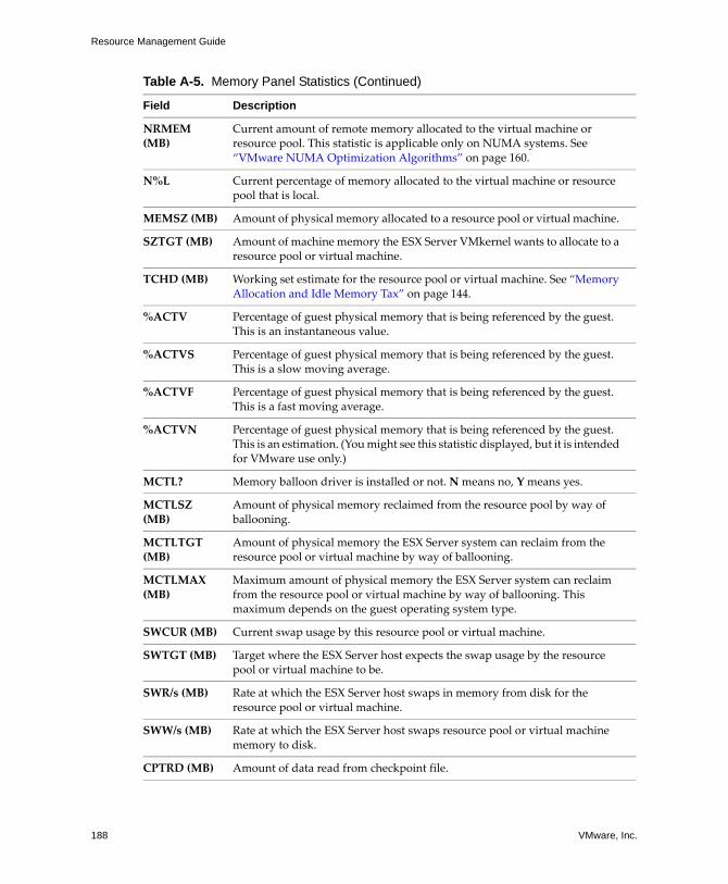
Resource Management Guide
188 VMware, Inc.
NRMEM (MB)
Current amount of remote memory allocated to the virtual machine or resource pool. This statistic is applicable only on NUMA systems. See “VMware NUMA Optimization Algorithms” on page 160.
N%L Current percentage of memory allocated to the virtual machine or resource pool that is local.
MEMSZ (MB) Amount of physical memory allocated to a resource pool or virtual machine.
SZTGT (MB) Amount of machine memory the ESX Server VMkernel wants to allocate to a resource pool or virtual machine.
TCHD (MB) Working set estimate for the resource pool or virtual machine. See “Memory Allocation and Idle Memory Tax” on page 144.
%ACTV Percentage of guest physical memory that is being referenced by the guest. This is an instantaneous value.
%ACTVS Percentage of guest physical memory that is being referenced by the guest. This is a slow moving average.
%ACTVF Percentage of guest physical memory that is being referenced by the guest. This is a fast moving average.
%ACTVN Percentage of guest physical memory that is being referenced by the guest. This is an estimation. (You might see this statistic displayed, but it is intended for VMware use only.)
MCTL? Memory balloon driver is installed or not. N means no, Y means yes.
MCTLSZ (MB)
Amount of physical memory reclaimed from the resource pool by way of ballooning.
MCTLTGT (MB)
Amount of physical memory the ESX Server system can reclaim from the resource pool or virtual machine by way of ballooning.
MCTLMAX (MB)
Maximum amount of physical memory the ESX Server system can reclaim from the resource pool or virtual machine by way of ballooning. This maximum depends on the guest operating system type.
SWCUR (MB) Current swap usage by this resource pool or virtual machine.
SWTGT (MB) Target where the ESX Server host expects the swap usage by the resource pool or virtual machine to be.
SWR/s (MB) Rate at which the ESX Server host swaps in memory from disk for the resource pool or virtual machine.
SWW/s (MB) Rate at which the ESX Server host swaps resource pool or virtual machine memory to disk.
CPTRD (MB) Amount of data read from checkpoint file.
Table A-5. Memory Panel Statistics (Continued)
Field Description

VMware, Inc. 189
Appendix: Performance Monitoring Utilities: resxtop and esxtop
CPTTGT (MB)
Size of checkpoint file.
ZERO (MB) Resource pool or virtual machine physical pages that are zeroed.
SHRD (MB) Resource pool or virtual machine physical pages that are shared.
SHRDSVD (MB)
Machine pages that are saved because of resource pool or virtual machine shared pages.
OVHD (MB) Current space overhead for resource pool. See “Understanding Memory Overhead” on page 142.
OVHDMAX (MB)
Maximum space overhead that might be incurred by resource pool or virtual machine. See “Understanding Memory Overhead” on page 142.
OVHDUW (MB)
Current space overhead for a user world. (You might see this statistic displayed, but it is intended for VMware use only.)
GST_NDx (MB)
Guest memory allocated for a resource pool on NUMA node x. This statistic is applicable on NUMA systems only.
OVD_NDx (MB)
VMM overhead memory allocated for a resource pool on NUMA node x. This statistic is applicable on NUMA systems only.
Table A-6. Memory Panel Interactive Commands
Command Description
M Sort resource pools or virtual machines by Group Mapped column.
B Sort resource pools or virtual machines by Group Memctl column.
N Sort resource pools or virtual machines by GID column. This is the default sort order.
V Display virtual machine instances only.
Table A-5. Memory Panel Statistics (Continued)
Field Description

Resource Management Guide
190 VMware, Inc.
Storage Panels
Three storage panels display server‐wide storage utilization statistics.
This section describes the three storage panels:
“Storage Adapter Panel” on page 190
“Storage Device Panel” on page 193
“Virtual Machine Storage Panel” on page 196
Storage Adapter Panel
The Storage Adapter panel displays the information shown in Figure A‐4. Statistics are
aggregated per storage adapter by default. Statistics can also be viewed per storage
channel, target, LUN, or world using a LUN.
Figure A-4. Storage Adapter Panel
Table A-7. Storage Adapter Panel Statistics
Column Description
ADAPTR Name of the storage adapter.
CID Storage adapter channel ID. This ID is visible only if the corresponding adapter is expanded. See the interactive command e below.
TID Storage adapter channel target ID. This ID is visible only if the corresponding adapter and channel are expanded. See the interactive commands e and a below.
LID Storage adapter channel target LUN ID. This ID is visible only if the corresponding adapter, channel and target are expanded. See the interactive commands e, a, and t below.
WID Storage adapter channel target LUN world ID. This ID is visible only if the corresponding adapter, channel, target and LUN are expanded. See interactive commands e, a, t, and l below.
NCHNS Number of channels.
NTGTS Number of targets.
NLUNS Number of LUNs.
NVMS Number of worlds.
SHARES Number of shares.

VMware, Inc. 191
Appendix: Performance Monitoring Utilities: resxtop and esxtop
BLKSZ Block size in bytes. This statistic is applicable only to LUNs.
AQLEN Storage adapter queue depth. Maximum number of ESX Server VMkernel active commands that the adapter driver is configured to support.
LQLEN LUN queue depth. Maximum number of ESX Server VMkernel active commands that the LUN is allowed to have.
WQLEN World queue depth. Maximum number of ESX Server VMkernel active commands that the world is allowed to have. This is a per LUN maximum for the world.
%USD Percentage of queue depth (adapter, LUN or world) used by ESX Server VMkernel active commands.
LOAD Ratio of ESX Server VMkernel active commands plus ESX Server VMkernel queued commands to queue depth (adapter, LUN or world).
ACTV Number of commands in the ESX Server VMkernel that are currently active.
QUED Number of commands in the ESX Server VMkernel that are currently queued.
CMDS/s Number of commands issued per second.
READS/s Number of read commands issued per second.
WRITES/s Number of write commands issued per second.
MBREAD/s Megabytes read per second.
MBWRTN/s Megabytes written per second.
DAVG/cmd Average device latency per command, in milliseconds.
KAVG/cmd Average ESX Server VMkernel latency per command, in milliseconds.
GAVG/cmd Average virtual machine operating system latency per command, in milliseconds.
DAVG/rd Average device read latency per read operation, in milliseconds.
KAVG/rd Average ESX Server VMkernel read latency per read operation, in milliseconds.
GAVG/rd Average guest operating system read latency per read operation, in milliseconds.
DAVG/wr Average device write latency per write operation, in milliseconds.
KAVG/wr Average ESX Server VMkernel write latency per write operation, in milliseconds.
GAVG/wr Average guest operating system write latency per write operation, in milliseconds.
Table A-7. Storage Adapter Panel Statistics (Continued)
Column Description
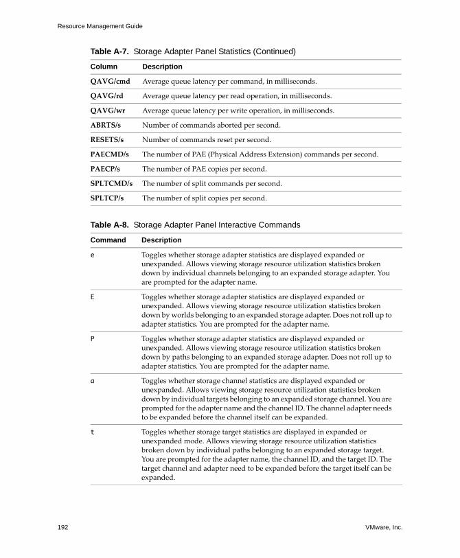
Resource Management Guide
192 VMware, Inc.
QAVG/cmd Average queue latency per command, in milliseconds.
QAVG/rd Average queue latency per read operation, in milliseconds.
QAVG/wr Average queue latency per write operation, in milliseconds.
ABRTS/s Number of commands aborted per second.
RESETS/s Number of commands reset per second.
PAECMD/s The number of PAE (Physical Address Extension) commands per second.
PAECP/s The number of PAE copies per second.
SPLTCMD/s The number of split commands per second.
SPLTCP/s The number of split copies per second.
Table A-8. Storage Adapter Panel Interactive Commands
Command Description
e Toggles whether storage adapter statistics are displayed expanded or unexpanded. Allows viewing storage resource utilization statistics broken down by individual channels belonging to an expanded storage adapter. You are prompted for the adapter name.
E Toggles whether storage adapter statistics are displayed expanded or unexpanded. Allows viewing storage resource utilization statistics broken down by worlds belonging to an expanded storage adapter. Does not roll up to adapter statistics. You are prompted for the adapter name.
P Toggles whether storage adapter statistics are displayed expanded or unexpanded. Allows viewing storage resource utilization statistics broken down by paths belonging to an expanded storage adapter. Does not roll up to adapter statistics. You are prompted for the adapter name.
a Toggles whether storage channel statistics are displayed expanded or unexpanded. Allows viewing storage resource utilization statistics broken down by individual targets belonging to an expanded storage channel. You are prompted for the adapter name and the channel ID. The channel adapter needs to be expanded before the channel itself can be expanded.
t Toggles whether storage target statistics are displayed in expanded or unexpanded mode. Allows viewing storage resource utilization statistics broken down by individual paths belonging to an expanded storage target. You are prompted for the adapter name, the channel ID, and the target ID. The target channel and adapter need to be expanded before the target itself can be expanded.
Table A-7. Storage Adapter Panel Statistics (Continued)
Column Description

VMware, Inc. 193
Appendix: Performance Monitoring Utilities: resxtop and esxtop
Storage Device Panel
The storage device panel displays server‐wide storage utilization statistics. By default,
the information is grouped per storage device. You can also group the statistics per
path, per world, or per partition.
Figure A-5. Storage Device Panel
l Toggles whether path is displayed in expanded or unexpanded mode. Allows viewing storage resource utilization statistics broken down by individual worlds utilizing an expanded storage path. You are prompted for the adapter name, the channel ID, the target ID, and the LUN ID. The path target, channel, and adapter must be expanded before the path itself can be expanded.
r Sorts by Reads column.
w Sorts by Writes column.
R Sorts by MB read column.
T Sorts by MB written column.
N Sorts first by ADAPTR column, then by CID column within each ADAPTR, then by TID column within each CID, then by LID column within each TID, and finally by WID column within each LID. This is the default sort order.
Table A-9. Storage Device Panel Statistics
Column Description
DEVICE Name of the storage device.
PATH Path name. This name is visible only if the corresponding device is expanded to paths. See the interactive command p below.
WORLD World ID. This ID is visible only if the corresponding device is expanded to worlds. See the interactive command e below. The world statistics are per world per device.
PARTITION Partition ID. This ID is visible only if the corresponding device is expanded to partitions. See interactive command t below.
Table A-8. Storage Adapter Panel Interactive Commands (Continued)
Command Description

Resource Management Guide
194 VMware, Inc.
NPH Number of paths.
NWD Number of worlds.
NPN Number of partitions.
SHARES Number of shares. This statistic is applicable only to worlds.
BLKSZ Block size in bytes.
NUMBLKS Number of blocks of the device.
DQLEN Storage device queue depth. This is the maximum number of ESX Server VMkernel active commands that the device is configured to support.
WQLEN World queue depth. This is the maximum number of ESX Server VMkernel active commands that the world is allowed to have. This is a per device maximum for the world. It is valid only if the corresponding device is expanded to worlds.
ACTV Number of commands in the ESX Server VMkernel that are currently active. This statistic is applicable only to worlds and devices.
QUED Number of commands in the ESX Server VMkernel that are currently queued. This statistic is applicable only to worlds and devices.
%USD Percentage of the queue depth used by ESX Server VMkernel active commands. This statistic is applicable only to worlds and devices.
LOAD Ratio of ESX Server VMkernel active commands plus ESX Server VMkernel queued commands to queue depth. This statistic is applicable only to worlds and devices.
CMDS/s Number of commands issued per second.
READS/s Number of read commands issued per second.
WRITES/s Number of write commands issued per second.
MBREAD/s Megabytes read per second.
MBWRTN/s Megabytes written per second.
DAVG/cmd Average device latency per command in milliseconds.
KAVG/cmd Average ESX Server VMkernel latency per command in milliseconds.
GAVG/cmd Average guest operating system latency per command in milliseconds.
QAVG/cmd Average queue latency per command in milliseconds.
DAVG/rd Average device read latency per read operation in milliseconds.
KAVG/rd Average ESX Server VMkernel read latency per read operation in milliseconds.
Table A-9. Storage Device Panel Statistics (Continued)
Column Description

VMware, Inc. 195
Appendix: Performance Monitoring Utilities: resxtop and esxtop
GAVG/rd Average guest operating system read latency per read operation in milliseconds.
QAVG/rd Average queue read latency per read operation in milliseconds.
DAVG/wr Average device write latency per write operation in milliseconds.
KAVG/wr Average ESX Server VMkernel write latency per write operation in milliseconds.
GAVG/wr Average guest operating system write latency per write operation in milliseconds.
QAVG/wr Average queue write latency per write operation in milliseconds.
ABRTS/s Number of commands aborted per second.
RESETS/s Number of commands reset per second.
PAECMD/s Number of PAE commands per second. This statistic is applicable only to paths.
PAECP/s Number of PAE copies per second. This statistic is applicable only to paths.
SPLTCMD/s Number of split commands per second. This statistic is applicable only to paths.
SPLTCP/s Number of split copies per second. This statistic is applicable only to paths.
Table A-10. Storage Device Panel Interactive Commands
Command Description
e Expand or roll up storage world statistics. This command allows you to view storage resource utilization statistics separated by individual worlds belonging to an expanded storage device. You are prompted for the device name. The statistics are per world per device.
p Expand or roll up storage path statistics. This command allows you to view storage resource utilization statistics separated by individual paths belonging to an expanded storage device. You are prompted for the device name.
t Expand or roll up storage partition statistics. This command allows you to view storage resource utilization statistics separated by individual partitions belonging to an expanded storage device. You are prompted for the device name.
r Sort by READS/s column.
w Sort by WRITES/s column.
R Sort by MBREAD/s column.
Table A-9. Storage Device Panel Statistics (Continued)
Column Description

Resource Management Guide
196 VMware, Inc.
Virtual Machine Storage Panel
This panel displays virtual machine‐centric storage statistics. By default, statistics are
aggregated on a per‐resource‐pool basis by default. One virtual machine has one
corresponding resource pool, so the panel really displays statistics on a
per‐virtual‐machine basis. You can also view statistics on a per‐world, or a
per‐world‐per‐device basis.
Figure A-6. Virtual Machine Storage Panel
T Sort by MBWRTN column.
N Sort first by DEVICE column, then by PATH, WORLD, and PARTITION column. This is the default sort order.
Table A-11. Virtual Machine Storage Panel Statistics
Column Description
ID Resource pool ID of the running world’s resource pool or the world ID of the running world.
GID Resource pool ID of running world’s resource pool.
NAME Name of running world’s resource pool or name of the running world.
Device Storage device name. This name is visible only if corresponding world is expanded to devices. See the interactive command i below.
NWD Number of worlds.
NDV The number of devices. This number is valid only if the corresponding resource pool is expanded to worlds
SHARES Number of shares. This statistic is only applicable to worlds. It is valid only if the corresponding resource pool is expanded to worlds
BLKSZ Block size in bytes. It is valid only if the corresponding world is expanded to devices.
NUMBLKS Number of blocks of the device. It is valid only if the corresponding world is expanded to devices.
Table A-10. Storage Device Panel Interactive Commands (Continued)
Command Description

VMware, Inc. 197
Appendix: Performance Monitoring Utilities: resxtop and esxtop
DQLEN Storage device queue depth. This is the maximum number of ESX Server VMkernel active commands that the device is configured to support. The displayed number is valid only if the corresponding world is expanded to devices.
WQLEN World queue depth. This column displays the maximum number of ESX Server VMkernel active commands that the world is allowed to have. The number is valid only if the corresponding world is expanded to devices. This is a per device maximum for the world.
ACTV Number of commands in the ESX Server VMkernel that are currently active. This number is applicable only to worlds and devices.
QUED Number of commands in the ESX Server VMkernel that are currently queued. This number is applicable only to worlds and devices.
%USD Percentage of queue depth used by ESX Server VMkernel active commands. This number is applicable only to worlds and devices.
LOAD Ratio of ESX Server VMkernel active commands plus ESX Server VMkernel queued commands to queue depth. This number is applicable only to worlds and devices.
CMDS/s Number of commands issued per second.
READS/s Number of read commands issued per second.
WRITES/s Number of write commands issued per second.
MBREAD/s Megabytes read per second.
MBWRTN/s Megabytes written per second.
DAVG/cmd Average device latency per command in milliseconds.
KAVG/cmd Average ESX Server VMkernel latency per command in milliseconds.
GAVG/cmd Average guest operating system latency per command in milliseconds.
QAVG/cmd Average queue latency per command in milliseconds.
DAVG/rd Average device read latency per read operation in milliseconds.
KAVG/rd Average ESX Server VMkernel read latency per read operation in milliseconds.
GAVG/rd Average guest operating system read latency per read operation in milliseconds.
QAVG/rd Average queue read latency per read operation in milliseconds.
DAVG/wr Average device write latency per write operation in milliseconds.
KAVG/wr Average ESX Server VMkernel write latency per write operation in milliseconds.
Table A-11. Virtual Machine Storage Panel Statistics (Continued)
Column Description

Resource Management Guide
198 VMware, Inc.
GAVG/wr Average guest operating system write latency per write operation in milliseconds.
QAVG/wr Average queue write latency per write operation in milliseconds.
ABRTS/s Number of commands aborted per second in milliseconds.
RESETS/s Number of commands reset per second in milliseconds.
Table A-12. Virtual Machine Storage Panel Interactive Commands
Command Description
e Expand or roll up storage world statistics. Allows you to view storage resource utilization statistics separated by individual worlds belonging to a group. You are prompted to enter the group ID. The statistics are per world.
l Expand or roll up storage device, that is LUN, statistics. Allows you to view storage resource utilization statistics separated by individual devices belonging to an expanded world. You are prompted to enter the world ID.
V Display virtual machine instances only.
r Sort by READS/s column.
w Sort by WRITES/s column.
R Sort by MBREAD/s column.
T Sort by MBWRTN/s column.
N Sort first by virtual machine column, and then by WORLD column. This is the default sort order.
Table A-11. Virtual Machine Storage Panel Statistics (Continued)
Column Description

VMware, Inc. 199
Appendix: Performance Monitoring Utilities: resxtop and esxtop
Network Panel
The panel shown in Figure A‐7 displays server‐wide network utilization statistics.
Statistics are arranged by port for each virtual network device configured. For physical
network adapter statistics, see the row corresponding to the port to which the physical
network adapter is connected. For statistics on a virtual network adapter configured in
a particular virtual machine, see the row corresponding to the port to which the virtual
network adapter is connected.
Figure A-7. Network Panel
Table A-13. Network Panel Statistics
Column Description
PORT Virtual network device port ID.
UPLINK Y means the corresponding port is an uplink. N means it is not.
UP Y means the corresponding link is up. N means it is not.
SPEED Link speed in MegaBits per second.
FDUPLX Y means the corresponding link is operating at full duplex. N means it is not.
USED Virtual network device port user.
DTYP Virtual network device type. H means HUB and S means switch.
DNAME Virtual network device name.
PKTTX/s Number of packets transmitted per second.
PKTRX/s Number of packets received per second.
MbTX/s MegaBits transmitted per second.
MbRX/s MegaBits received per second.
%DRPTX Percentage of transmit packets dropped.
%DRPRX Percentage of receive packets dropped.

Resource Management Guide
200 VMware, Inc.
Using the Utilities in Batch ModeBatch mode allows you to collect and save resource utilization statistics in a file. To run
in batch mode, you must first prepare for batch mode.
To prepare for running resxtop or esxtop in batch mode
1 Run resxtop (or esxtop) in interactive mode.
2 In each of the panels, select the columns you want.
3 Save this configuration to a file (by default ~/.esxtop310rc) using the W interactive command.
To run resxtop or esxtop in batch mode
1 Start resxtop (or esxtop) to redirect the output to a file. For example:
esxtop -b > my_file.csv
The file name must have a .csv extension. The utility does not enforce this, but the post‐processing tools require it.
2 Process statistics collected in batch mode using tools such as Microsoft Excel and
Perfmon.
In batch mode, resxtop (or esxtop) does not accept interactive commands. In batch
mode, the utility runs until it produces the number of iterations requested (see
command‐line option n, below, for more details), or until you kill the process by
pressing Ctrl+c.
The command‐line options in Table A‐15 are available in batch mode.
Table A-14. Network Panel Interactive Commands
Command Description
T Sorts by Mb Tx column.
R Sorts by Mb Rx column.
t Sorts by Packets Tx column.
r Sorts by Packets Rx column.
N Sorts by PORT ID column. This is the default sort order.

VMware, Inc. 201
Appendix: Performance Monitoring Utilities: resxtop and esxtop
Using the Utilities in Replay ModeIn replay mode, resxtop (or esxtop) replays resource utilization statistics collected using vm-support. See the vm-support man page.
To run in replay mode, you must first prepare for replay mode.
To prepare for running resxtop or esxtop in replay mode
1 Run vm-support in snapshot mode on the ESX Server service console (ESX Server
3 only).
Use the following command:
vm-support -S -d duration -i interval
2 Unzip and untar the resulting tar file so that resxtop (or esxtop) can use it in replay mode.
Table A-15. Command-Line Options in Batch Mode
Option Description
a Show all statistics. This option overrides configuration file setups and shows all statistics. The configuration file can be the default ~/.esxtop310rc configuration file or a user‐defined configuration file.
b Runs resxtop (or esxtop) in batch mode.
c <filename> Load a user‐defined configuration file. If the -c option is not used, the default configuration file name is ~/.esxtop310rc. Create your own configuration file, specifying a different file name, using the W single‐key interactive command. See “Interactive Mode Single‐Key Commands” on page 180 for information about W.
d Specifies the delay between statistics snapshots. The default is five seconds. The minimum is two seconds. If a delay of less than two seconds is specified, the delay is set to two seconds.
n Number of iterations. resxtop (or esxtop) collects and saves statistics this number of times, and then exits.
server The name of the remote server host to connect to (required, resxtop only).
portnumber The port number to connect to on the remote server. The default port is 443, and unless this has been changed on the server, this option is not needed. (resxtop only)
username The user name to be authenticated when connecting to the remote host. You are prompted by the remote server for a password, as well (resxtop only).

Resource Management Guide
202 VMware, Inc.
To run resxtop or esxtop in replay mode
Enter the following at the command‐line prompt:
resxtop -R <vm-support_dir_path>
Additional command‐line options are listed in Table A‐16.
You do not have to run replay mode on the ESX Server service console.
Replay mode can be run to produce output in the same style as batch mode (see the
command‐line option b, below).
In replay mode, resxtop (or esxtop) accepts the same set of interactive commands as
in interactive mode and runs until there are no more snapshots collected by
vm-support to be read or until the requested number of iterations are completed (see
the command‐line option n for more details).
Table A‐16 lists the command‐line options available for resxtop (or esxtop) replay mode.
Table A-16. Command-Line Options in Replay Mode
Option Description
R Path to the vm‐support collected snapshot’s directory.
a Show all statistics. This option overrides configuration file setups and shows all statistics. The configuration file can be the default ~/.esxtop310rc configuration file or a user‐defined configuration file.
b Runs resxtop (or esxtop) in Batch mode.
c <filename> Load a user‐defined configuration file. If the -c option is not used, the default configuration file name is ~/.esxtop310rc. Create your own configuration file and specify a different file name using the W single‐key interactive command. See “Interactive Mode Single‐Key Commands” on page 180 for information about W.
d Specifies the delay between panel updates. The default is five seconds. The minimum is two seconds. If a delay of less than two seconds is specified, the delay is set to two seconds.
n Number of iterations. resxtop (or esxtop) updates the display this number of times and then exits.

VMware, Inc. 203VMware, Inc. 203
Index
Aadmission control 22, 23
CPU 133
DRS 114
HA 95, 115
resource pools 47
strict 60, 76, 86, 117, 121
with expandable resource pools 29
advanced attributes 151
CPU 152
HA 126
hosts 151
memory 153
NUMA 154
virtual machines 155
affinity
CPU 38, 132
CPU, and hyperthreading 139
defined 80
memory, NUMA nodes 166
potential issues 133
rules, using 110
algorithms, NUMA 160
AMD Opteron-based systems 164
anti-affinity 80
applications
CPU-bound 131
deploying 171
single-threaded 131
architecture, ESX Server 36
automation level 94
and DRS recommendations 60
distributed power management 68, 95
automation modes, virtual machines 116
available memory 15
Bballooning, memory 147
best practices 169
Ccluster creation overview 93
cluster features, choosing 94
cluster resource pools 46
clusters
adding hosts 32, 114
adding managed hosts 104, 122
adding unmanaged hosts 105, 122
adding virtual machines 113, 114
creating 30, 31, 89, 94, 96
customizing 30, 31
distributed power management 23, 30, 60, 68
DRS 57
DRS, adding hosts 104
HA 90
introduction 59
invalid 107
powering on virtual machines 114
prerequisites 89
processor compatibility 91
removing hosts 116
removing virtual machines 115
resource pools 56
shared storage 91

Resource Management Guide
204 VMware, Inc.
shared VMFS volume 91
summary page 97
virtual machines 113
VirtualCenter failure 61
CPU
admission control 133
advanced attributes 152
managing allocation 38
overcommitment 19
virtual machines 19
CPU affinity 38, 132, 133
hyperthreading 139
NUMA 165
NUMA nodes 165
potential issues 133
CPU panel
esxtop 182
resxtop 182
CPU Reservation 16
CPU Unreserved 16
CPU virtualization 39, 130
CPU.MachineClearThreshold 139, 152
CPU-bound applications 131
custom automation mode 116
Ddelegation of control through resource
pools 45
device drivers 37
disabled virtual machine 116
disk resources 35
distributed power management 30, 60
and admission control 23
automation level 68, 95
enabling 68
DNS 90, 125
short name 90
DRS
action history 101
adding managed hosts 104
adding unmanaged hosts 105
admission control 114
affinity rules 110
automation level 94
clusters, adding hosts 104
custom automation mode 116
customizing virtual machines 116
disabled virtual machine 116
fully automatic 95
host removal and virtual machines 107
initial placement 60, 62
introduction 62, 103
load balancing 60
maintenance mode 72
manual 95
migration 60
migration recommendations 68
overview 60
partially automatic 95
recommendation dependencies 108
recommendations 107
recommendations page 100
recommendations, and automation level 60
reconfiguring 109
red clusters 85
rules 112
turning off 109
using together with HA 80
virtual machine migration 66
VMotion network 89
DRS clusters 70
DRS recommendations page 100
DRS Resource Distribution histograms 99
DRS rules 111
dual-processor virtual machine 19
dynamic load balancing, NUMA 161
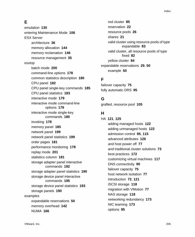
VMware, Inc. 205
Index
Eemulation 130
entering Maintenance Mode 106
ESX Server
architecture 36
memory allocation 144
memory reclamation 146
resource management 35
esxtop
batch mode 200
command-line options 178
common statistics description 180
CPU panel 182
CPU panel single-key commands 185
CPU panel statistics 183
interactive mode 179
interactive mode command-line options 179
interactive mode single-key commands 180
invoking 178
memory panel 185
network panel 199
network panel statistics 199
order pages 181
performance monitoring 178
replay mode 201
statistics column 181
storage adapter panel interactive commands 192
storage adapter panel statistics 190
storage device panel interactive commands 195
storage device panel statistics 193
storage panels 190
examples
expandable reservations 50
memory overhead 142
NUMA 166
red cluster 85
reservation 22
resource pools 26
shares 21
valid cluster using resource pools of type expandable 83
valid cluster, all resource pools of type fixed 82
yellow cluster 84
expandable reservations 29, 50
example 50
Ffailover capacity 75
fully automatic DRS 95
Ggrafted, resource pool 105
HHA 121, 125
adding managed hosts 122
adding unmanaged hosts 122
admission control 95, 115
advanced attributes 126
and host power off 77
and traditional cluster solutions 73
best practices 172
customizing virtual machines 117
DNS connectivity 90
failover capacity 75
host network isolation 77
introduction 72, 121
iSCSI storage 118
migration with VMotion 77
NAS storage 118
networking redundancy 173
NIC teaming 173
options 95

Resource Management Guide
206 VMware, Inc.
red clusters 86
redundant network paths 90
shared storage 90
turning off 125
using together with DRS 80
HA clusters
adding hosts 122
maintenance mode 78
planning 75
high, shares 20, 21
histograms,DRS Resource Distribution 99
home nodes, NUMA 160
host isolation response 96, 117, 124
host network isolation 77
host resource pools 46
hosts
adding to cluster 114
adding to DRS clusters 104, 105
adding to HA clusters 122
entering maintenance mode 106
losing resource pool hierarchy 105
memory use 145
removing and invalid clusters 107
removing and resource pool hierarchies 106
removing from clusters 116
resource information 14
hyperthreading 135, 136, 137
CPU affinity 139
CPU.MachineClearThreshold 139
disabling 40
disabling quarantining 152
performance implications 135
quarantining 139
hyperthreading modes
any 138
internal 138
none 138
Iidle memory tax 144, 146
initial placement 60, 62
NUMA 160
invalid clusters, host removal 107
iSCSI storage
HA 118
isolation through resource pools 45
Llimit
attribute 22
hyperthreading 138
pros and cons 22
resource pools 25
load balancing 60
DRS 30
migration recommendations 112
virtual machines, migration 66
logical processors 40, 134
low, shares 20, 21
Mmaintenance mode 71, 72, 106
entering 106
HA clusters 78
manual DRS 95
Mem.AllocGuestLargePage 153
Mem.AllocUseGuestPool 153
Mem.AllocUsePSharePool 153
Mem.BalancePeriod 153
Mem.CtlMaxPercent 153
Mem.IdleTax 146, 153
Mem.SamplePeriod 145, 153
Mem.ShareScanGHz 151, 153
Mem.ShareScanTime 151, 153
memory
advanced attributes 153
available 15

VMware, Inc. 207
Index
managing allocation 39
overhead 42
reclaiming unused 146
service console 15, 40
sharing across virtual machines 150
virtual machines 18
virtualization basics 40
VMkernel memory 171
memory affinity, NUMA 166
memory balloon driver 147
memory idle tax 144, 146
Mem.IdleTax 153
memory overcommitment 42, 150
memory overhead 142
examples 142
Memory Reservation 17
memory sharing 42
Memory Unreserved 17
memory virtualization 39
migration recommendations 68
migration threshold 67
migration with VMotion, failure, and HA 77
multicore processors 134
NNAS storage, HA 118
network resources 35
NIC teaming 173
normal, shares 20, 21
NUMA
advanced attributes 154
AMD Opteron-based systems 164
CPU affinity 165
CPU assignment 166
dynamic load balancing 161
example 166
home nodes and initial placement 160
introduction 158
manual controls 162
memory affinity 166
optimization algorithms 160
page migration 161
transparent page sharing 162
using with ESX server 157
NUMA scheduling 159
Numa.AutoMemAffinity 154
Numa.MigImbalanceThreshold 154
Numa.PageMigEnable 154
Numa.RebalanceCoresNode 154
Numa.RebalanceCoresTotal 154
Numa.RebalanceEnable 154
Numa.RebalancePeriod 154
OOpteron 164
overcommitment 42, 150
overcommitted cluster 84
overhead 142
examples 142
overhead memory 42
Ppage migration, NUMA 161
partially automatic DRS 95
performance 36
CPU-bound applications 131
monitoring 54
performance monitoring, esxtop 178
performance monitoring, resxtop 178
physical and logical processors 40
physical memory usage 145
physical processors 40
processors
logical 40
multicore 134
physical 40
processor-specific behavior 131

Resource Management Guide
208 VMware, Inc.
Qquarantining, hyperthreading 139
Rred clusters 85
red DRS cluster 85
red HA cluster 86
redundant network paths for HA 90
Remote CLI 177
reservation 16
attribute 21
example 22
hyperthreading 138
resource pools 25
reservation type 25
resource management
best practices 169
concepts 33
resource pools 46
adding virtual machines 55
admission control 47
attributes, changing 54
clusters 56
creating 25, 26, 48
customizing 25, 26
delegation of control 45
DRS clusters 70
example 26
grafted 105
hierarchies, host removal 106
information 50
introduction 43, 44
isolation 45
performance 54
removing virtual machines 56
reservation type 25
resource allocation tab 52
root resource pool 44
siblings 44
summary tab 51
resources, reserving 20
resxtop
batch mode 200
common statistics description 180
CPU panel 182
CPU panel single-key commands 185
CPU panel statistics 183
interactive mode 179
interactive mode command-line options 179
interactive mode single-key commands 180
memory panel 185
network panel 199
network panel statistics 199
options 178
order pages 181
performance monitoring 178
replay mode 201
statistics column 181
storage adapter panel interactive commands 192
storage adapter panel statistics 190
storage device panel interactive commands 195
storage device panel statistics 193
storage panels 190
root resource pool 44
rules 111
deleting 112
disabling 112
DRS 112
editing 111
results 112
SSAN and HA 90
sched.mem.maxmemctl 147, 156

VMware, Inc. 209
Index
sched.mem.pshare.enable 156
sched.swap.dir 156
sched.swap.file 156
sched.swap.persist 156
secondary service console 174
server configuration for hyperthreading 137
service console
memory use 15, 40
redundancy 174
shares 20
example 21
high 20
low 20
normal 20
ratio 20
resource pools 25
sharing memory 42
siblings 44
single-processor virtual machine 19
single-threaded applications 131
SMP virtual machines 131
standby mode 60, 63, 68, 72
stars, migration threshold 67
statistics, esxtop 180
statistics, resxtop 180
swap space 148, 150
Linux systems 148
Windows systems 148
swapping 148
Tthreads 134
threshold, migration 67
traditional clustering solutions 73
Vvalid clusters 81
example 83
Virtual Infrastructure SDK 38
virtual machine attributes
changing 23
shares, reservation, and limit 20
Virtual Machine File System (VMFS) 37, 77, 91
virtual machine migration 66
virtual machine monitoring 96, 119
virtual machines
adding during cluster creation 113
adding to cluster 113, 114
adding to resource pools 55
advanced attributes 155
assigning to a specific processor 133
automation modes 116
changing resource allocation 23
configuration file 93
CPU 19
creating (best practice) 170
customizing for DRS 116
customizing for HA 117
deploying (best practice) 170
deploying applications 171
deploying operating system 171
disabled (DRS) 116
dual-processor 19
host removal 107
memory 18, 41
memory overhead 142
monitor 139
monitoring 96, 119
number of virtual processors 131
removing from cluster 115
removing from resource pools 56
resource allocation 18
single-processor 19
virtual memory 139
virtual memory in virtual machines 139
virtual processors per virtual machine 131
VM restart priority 117, 124

Resource Management Guide
210 VMware, Inc.
VMFS (Virtual Machine File System) 37, 77, 91
VMkernel 37
hardware interface layer 37
memory 171
resource manager 37
VMkernel port
redundancy 174
VMM 37, 139
vmmemctl 147
Mem.CtlMaxPercent 153
sched.mem.maxmemctl 156
VMotion requirements 91
Wwake on LAN (WOL) 72
working set size 144
Yyellow cluster 84

VMware, Inc. Update–1
Updates for the Resource Management Guide
Last Updated: June 12, 2009
This document provides updates to the Update 2 Release for ESX Server 3.5,
ESX Server 3i version 3.5, VirtualCenter 2.5 version of the Resource Management Guide.
Updated descriptions, procedures, and graphics are organized by page number so that
you can easily locate the areas of the guide that have changes. If the change spans
multiple sequential pages, this document provides the starting page number only.
The following is a list of updates to the Resource Management Guide:
Update for the Failover Capacity Section on Page 75
Update for the Cluster Prerequisites Section on Page 89
Update for the Clusters Enabled for HA Section on Page 90
Update for the Shared Storage Section on Page 91
Update for the Shared VMFS Volume Section on Page 91
Update for the Top DRS Resource Distribution Chart Section on Page 99
Update for the Configuring and Unconfiguring HA on a Host Section on Page 125
Update for the Virtualization and Processor‐Specific Behavior Section on Page 131
Update for the Setting Advanced Host Attributes Section on Page 151
Update for the Networking Best Practices Section on Page 172
Update for the CPU Panel Section on Page 183
Update for the Failover Capacity Section on Page 75The first note that appears in the Failover Capacity section “You can allow the cluster
to power on virtual machines even when they violate availability constraints. If you do
that, the result is a red cluster, which means that failover guarantees might no longer
be valid.” is incorrect and should be disregarded

Updates for the Resource Management Guide
Update–2 VMware, Inc.
Update for the Cluster Prerequisites Section on Page 89In addition to the prerequisites listed in the Cluster Prerequisites section, all the ESX
Server hosts in an HA‐enabled cluster should have compatible networks. Starting with
VirtualCenter 2.5 Update 2, HA has an enhanced network compliance check to increase
cluster reliability. This enhanced network compliance check helps to ensure correct
cluster‐wide heartbeat network paths.
VirtualCenter 2.5 Update 3 and later allows you to bypass this check to prevent HA
configuration problems. To bypass the check, add das.bypassNetCompatCheck=true to the HA advanced settings.
Update for the Clusters Enabled for HA Section on Page 90
The first note that appears in the Clusters Enabled for HA section states that “All hosts
in an HA cluster must have DNS configured so that the short host name (without the
domain suffix) of any host in the cluster can be resolved to the appropriate IP address
from any other host in the cluster.” This is incorrect and this requirement no longer
exists.
Update for the Shared Storage Section on Page 91 In the Shared Storage section, information on NAS storage support for shared storage
is added. The existing sentence is modified as follows: Shared storage is typically on a
storage area network (SAN) but can also be implemented using NAS shared storage.
Update for the Shared VMFS Volume Section on Page 91In the note that appears in the Shared VMFS Volume section, the sentence “This
requirement no longer applies if all source and destination hosts are ESX Server 3.5 or
higher” should be qualified to say “...ESX Server 3.5 or higher and using host‐local swap.”
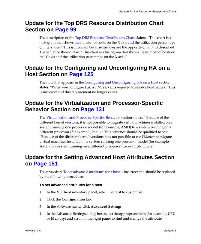
VMware, Inc. Update–3
Updates for the Resource Management Guide
Update for the Top DRS Resource Distribution Chart Section on Page 99
The description of the Top DRS Resource Distribution Chart claims: “This chart is a
histogram that shows the number of hosts on the X axis and the utilization percentage
on the Y axis.” This is incorrect because the axes are the opposite of what is described.
The sentence should read: “This chart is a histogram that shows the number of hosts on
the Y axis and the utilization percentage on the X axis.”
Update for the Configuring and Unconfiguring HA on a Host Section on Page 125
The note that appears in the Configuring and Unconfiguring HA on a Host section
states: “When you configure HA, a DNS server is required to resolve host names.” This
is incorrect and this requirement no longer exists.
Update for the Virtualization and Processor-Specific Behavior Section on Page 131
The Virtualization and Processor‐Specific Behavior section states: “ Because of the
different kernel versions, it is not possible to migrate virtual machines installed on a
system running one processor model (for example, AMD) to a system running on a
different processor (for example, Intel).” This sentence should be qualified to say:
“Because of the different kernel versions, it is not possible to use VMotion to migrate
virtual machines installed on a system running one processor model (for example,
AMD) to a system running on a different processor (for example, Intel).”
Update for the Setting Advanced Host Attributes Section on Page 151
The procedure To set advanced attributes for a host is incorrect and should be replaced
by the following procedure:
To set advanced attributes for a host
1 In the VI Client inventory panel, select the host to customize.
2 Click the Configuration tab.
3 In the Software menu, click Advanced Settings.
4 In the Advanced Settings dialog box, select the appropriate item (for example, CPU
or Memory) and scroll in the right panel to find and change the attribute.

Updates for the Resource Management Guide
Update–4 VMware, Inc.
Update for the Networking Best Practices Section on Page 172
In the Networking Best Practices section, a bullet point states: “Use DNS for name
resolution rather than the error‐prone method of manually editing the local /etc/hosts file on ESX Server hosts. If you do edit /etc/hosts, you must include
both long and short names.” This information is obsolete and should be ignored.
Update for the CPU Panel Section on Page 183The entry in Table A‐3 for %IDLE should also say: “The difference, %WAIT ‐ %IDLE,
of the VCPU worlds can be used to estimate guest I/O wait time. To find the VCPU
worlds, use the single‐key command e to expand a virtual machine and search for the
world NAME starting with ʺvcpu.ʺ The VCPU worlds might wait for other events
besides I/O events, so this measurement is only an estimate.