Embed Size (px)
Citation preview

TECHNICAL REPORT RDMR-WD-16-37
RREESSOONNAANNTT IINNDDUUCCTTIIVVEE PPOOWWEERR TTRRAANNSSFFEERR FFOORR NNOONNCCOONNTTAACCTT
LLAAUUNNCCHHEERR--MMIISSSSIILLEE IINNTTEERRFFAACCEE
Martin S. Heimbeck Weapons Development and Integration Directorate
Aviation and Missile Research, Development, and Engineering Center
And
Domenico de Ceglia National Research Council
Charles M. Bowden Laboratory Aviation and Missile Research, Development, and Engineering Center
Redstone Arsenal, AL 35898
August 2016
Distribution Statement A: Approved for public release; distribution is unlimited.

DESTRUCTION NOTICE
FOR CLASSIFIED DOCUMENTS, FOLLOW THE PROCEDURES IN DoD 5200.22-M, INDUSTRIAL SECURITY MANUAL, SECTION II-19 OR DoD 5200.1-R, INFORMATION SECURITY PROGRAM REGULATION, CHAPTER IX. FOR UNCLASSIFIED, LIMITED DOCUMENTS, DESTROY BY ANY METHOD THAT WILL PREVENT DISCLOSURE OF CONTENTS OR RECONSTRUCTION OF THE DOCUMENT.
DISCLAIMER
THE FINDINGS IN THIS REPORT ARE NOT TO BE CONSTRUED AS AN OFFICIAL DEPARTMENT OF THE ARMY POSITION UNLESS SO DESIGNATED BY OTHER AUTHORIZED DOCUMENTS.
TRADE NAMES
USE OF TRADE NAMES OR MANUFACTURERS IN THIS REPORT DOES NOT CONSTITUTE AN OFFICIAL ENDORSEMENT OR APPROVAL OF THE USE OF SUCH COMMERCIAL HARDWARE OR SOFTWARE.

i/ii (Blank)
REPORT DOCUMENTATION PAGE Form Approved OMB No. 074-0188
Public reporting burden for this collection of information is estimated to average 1 hour per response, including the time for reviewing instructions, searching existing data sources, gathering and maintaining the data needed, and completing and reviewing this collection of information. Send comments regarding this burden estimate or any other aspect of this collection of information, including suggestions for reducing this burden to Washington Headquarters Services, Directorate for Information Operations and Reports, 1215 Jefferson Davis Highway, Suite 1204, Arlington, VA 22202-4302, and to the Office of Management and Budget, Paperwork Reduction Project (0704-0188), Washington, DC 20503 1.AGENCY USE ONLY
2. REPORT DATE August 2016
3. REPORT TYPE AND DATES COVERED Final
4. TITLE AND SUBTITLE Resonant Inductive Power Transfer for Noncontact Launcher-Missile Interface
5. FUNDING NUMBERS
6. AUTHOR(S) Martin S. Heimbeck and Domenico de Ceglia
7. PERFORMING ORGANIZATION NAME(S) AND ADDRESS(ES)Commander, U.S. Army Research, Development, and Engineering Command ATTN: RDMR-WDS-R Redstone Arsenal, AL 35898-5000
8. PERFORMING ORGANIZATION REPORT NUMBER
TR-RDMR-WD-16-37
9. SPONSORING / MONITORING AGENCY NAME(S) AND ADDRESS(ES) 10. SPONSORING / MONITORING AGENCY REPORT NUMBER
11. SUPPLEMENTARY NOTES 12a. DISTRIBUTION / AVAILABILITY STATEMENT Approved for public release; distribution is unlimited.
12b. DISTRIBUTION CODE
A
13. ABSTRACT (Maximum 200 Words) This report discusses the design and implementation of a wireless power transfer system based on the concept of non-radiating inductive coupling.
14. SUBJECT TERMS Resonant Inductive Coupling, Wireless Power Transfer
15. NUMBER OF PAGES18
16. PRICE CODE
17. SECURITY CLASSIFICATION OF REPORT
UNCLASSIFIED
18. SECURITY CLASSIFICATION OF THIS PAGE
UNCLASSIFIED
19. SECURITY CLASSIFICATION OF ABSTRACT
UNCLASSIFIED
20. LIMITATION OF ABSTRACT
SAR NSN 7540-01-280-5500 Standard Form 298 (Rev. 2-89)
Prescribed by ANSI Std. Z39-18 298-102

iii
TABLE OF CONTENTS
Page
I. INTRODUCTION ................................................................................................... 1
II. BASIC INDUCTIVE COUPLING ........................................................................ 1
III. RESONANT INDUCTIVE COUPLING............................................................... 2
IV. SPIRAL COIL DESIGN ......................................................................................... 3
V. COIL AND RESONATOR SYSTEM CONSTRUCTION .................................. 9
REFERENCE........................................................................................................... 13
LIST OF ABBREVIATIONS, ACRONYMS, AND SYMBOLS ........................ 14
iv
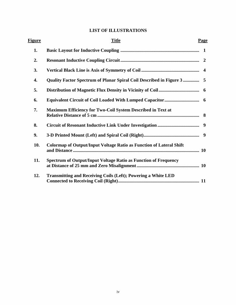
LIST OF ILLUSTRATIONS
Figure Title Page
1. Basic Layout for Inductive Coupling .................................................................... 1
2. Resonant Inductive Coupling Circuit .................................................................... 2
3. Vertical Black Line is Axis of Symmetry of Coil .................................................. 4
4. Quality Factor Spectrum of Planar Spiral Coil Described in Figure 3 .............. 5
5. Distribution of Magnetic Flux Density in Vicinity of Coil ................................... 6
6. Equivalent Circuit of Coil Loaded With Lumped Capacitor .............................. 6
7. Maximum Efficiency for Two-Coil System Described in Text at Relative Distance of 5 cm ........................................................................................ 8
8. Circuit of Resonant Inductive Link Under Investigation .................................... 9
9. 3-D Printed Mount (Left) and Spiral Coil (Right) ................................................ 9
10. Colormap of Output/Input Voltage Ratio as Function of Lateral Shift and Distance ............................................................................................................. 10
11. Spectrum of Output/Input Voltage Ratio as Function of Frequency at Distance of 25 mm and Zero Misalignment ...................................................... 10
12. Transmitting and Receiving Coils (Left); Powering a White LED Connected to Receiving Coil (Right) ...................................................................... 11

1
I. INTRODUCTION
The launcher-missile interface of rail launched missiles has been essentially unchanged for decades. It consisted of a large connector that protruded out of the missile body and housed pins that connected to the launcher interface as the missile was slit on the rail. A well-known example of such as connector was the shotgun connector on the Hellfire missile. These connector interfaces, although well-tested and generally reliable, are outdated, large, bulky, and incur high maintenance costs, especially in harsh conditions such as desert climates. Furthermore, emerging technologies produce smaller missiles, which may require smaller and improved connectivity solutions with respect to the physical footprint, data rates, and interoperability. This report discusses one type of missile-launcher connector in particular: a non-physical contact interface utilizing resonant inductive power transfer to augment wireless datalink solutions with the goal to develop an all (power and data) wireless short-range missile interface.
II. BASIC INDUCTIVE COUPLING
In its most basic and ideal form, inductive coupling is widely used in transformers, which can raise (for transmission over large distances) or lower (for use in devices) the Alternating Current (AC) voltage in a transmission line. As shown in Figure 1(a), a primary AC voltage, Vp, can be transformed to a new voltage, Vs, using two inductive coils which relate to their turn ratio, Np/Ns. In order to minimize transfer losses, these coils are usually wound on an iron core as illustrated by the black bar between the two coils. The relationship between the currents, I, in the primary and secondary circuits is also related by the winding turn ratio. Furthermore, due to the inductive coupling effect, the equivalent resistance, Req, and therefore current in the primary circuit depend on the load resistance, R, in the secondary coil, again according to the turn ratio. The simple ideal equations relating these quantities are
, , . (1)
Figure 1. Basic Layout for Inductive Coupling

2
In contrast to the ideal transformer, wireless inductive power transfer assumes that the coils are no longer physically connected by an iron core and that there is some distance between the two, as shown in Figure 1(b). For simplicity, it is assumed that the number of turns are the same for the primary and secondary coils; hence, the coils’ purpose is to transfer only power and not to change the voltage or current from the input. In order to calculate how well a voltage, current, and power are transferred from the primary coil to the secondary, consider the self-L and mutual inductances M. The self-inductance is the inductance of the coil in the absence of a secondary coil. It describes how a single coil generates an opposing Electromotive Force (EMF) due to a changing current passing through the coil. The mutual inductance relates two coils according to Faraday’s law, which calculates the magnetic flux in one coil due to a current in the other coil. If the current is alternating, the mutual inductance is equivalent to the change of the magnetic flux. As a rule of thumb, the mutual inductance decreases as the cubic power of the distance of separation between the two coils [1]. The transferred power is linearly related to the mutual coupling, causing the efficiency to drop equivalently. Clearly, a cubic power transfer efficiency dependence on the coil separation distance makes this approach highly unpractical. A more practical solution for wireless power transfer is to use a resonant circuit to efficiently couple the coils.
III. RESONANT INDUCTIVE COUPLING
The basic inductive circuit of Figure 1 can be tuned to resonate at a specific AC frequency and distance of separation with the introduction of a capacitor, forming an Inductor Capacitor (LC) or Resistor Inductor Capacitor (RLC) resonant oscillator circuit. Introducing the capacitor allows energy in the form of a charge to be stored on the capacitor. The capacitor then discharges through the inductive coil, which creates a magnetic field. Meanwhile, the capacitor charges again with opposite polarity. If the secondary circuit is built such that it is resonant to the magnetic field of the primary circuit, it can efficiently couple to the field producing a current in the secondary circuit. Figure 2 shows such as resonant circuit. The resonant AC frequency is calculated according to .
Figure 2. Resonant Inductive Coupling Circuit
In the following, a detailed description of a coil design is presented for the purpose of a wireless power transfer system based on the concept of nonradiating inductive coupling. The core of the system is the inductive link formed by two coupled spiral coils. The first step of the design is the full-wave analysis of a single coil and the evaluation of fundamental quantities such as the self-inductance, L; the self-capacitance, C; and the self-resistance, R. A spiral circular geometry in a planar configuration was considered for the coil design because of its
0 1/ LC
3
compatibility with standard circuit-fabrication techniques. Furthermore, such a planar coil lends itself to integration into on a circular missile body, possibly even inside of the composite missile body. Following the design, a proof of concept experiment demonstrating a successful wireless transfer of power is discussed.
IV. SPIRAL COIL DESIGN
As a design constraint, a coil radius, Rout, was chosen that was smaller than 5 centimeters (cm). The choice of the remaining design variables, such as number of turns, N; wire radius, r; type of metal; inner diameter of the coil, Rin; and spacing between turns, s, is dictated by several factors:
Desired inductance
Desired profile of the induced magnetic field
Target value of the intrinsic quality factor of the coil
Maximum operating frequency of the coil
For example, increasing the number of turns boosts the spiral inductance and the magnetic field strength around it. However, resistive and capacitive effects grow as well, due to the increased length of the spiral and to the smaller spacing between turns. As a result, both intrinsic quality factor and maximum operating frequency are affected. The cross section of the wire has a strong influence on the Direct Current (DC) resistance of the coil. Moreover, additional resistive components due to the skin and proximity effects are considered in the full-wave, frequency-domain analysis. These additional heating sources increase with the operating frequency and depend sensibly on the spiral geometry. Although other metals may be considered, copper was used for its high conductivity.
The AC magnetic analysis of the coil has been performed with a finite-element solver, approximating the structure with a set of concentric copper rings virtually connected in series. This approximation saves a significant amount of computational resources, since the problem is solved in two dimensions instead of three by exploiting the azimuthal symmetry of both the structure and induced magnetic field. Ampere’s law,
, (2)
is solved in the computational domain with a weak formulation for the magnetic vector potential A once a direct or alternating free current J=σE is injected at the spiral terminals. The conductivity of copper is assumed σCu=5.998·107 Siemens per meters (S/m); whereas, the surrounding medium (air) has zero conductivity. The discretization is very fine in the metallic wires, especially near the surfaces where most of the electric current is concentrated. The domain is closed with perfectly matched layers that absorb any evanescent and radiating field at a large distance from the coil. Note that analytical expressions of the self-impedance, as well as for mutual inductances in the presence of a coupled coil, exist for the simple geometry under investigation in the magneto-static approximation. For instance, the geometric mean approximation of the self-inductance of a spiral coil is
1 A J

4
(3)
where, is the average diameter of the spiral, , and
μ is the coil permittivity. The AC resistance of the coil can be approximated by taking into account only the skin depth effect but neglecting proximity effects:
(4)
in which is the total, linear coil length, f, is the frequency, and is
the effective copper area that supports conduction of free electrons. Analytical approximations, such as those reported in Equations 3 and 4, have been exploited as a coarse tool to find an initial design of the coil, and the Finite Element Model (FEM) has been then used to benchmark the analytical predictions and retrieve a more accurate description of the coil in the presence of additional effects, induced for example by the presence of surrounding objects (for example, mounts, wires, and other setup tools) or by substrates, nonlinear ferromagnetic materials, and proximity effects at higher frequencies.
The designed coil is sketched in Figure 3(a) with its actual proportions in Three-Dimensional (3-D), while the Two-Dimensional (2-D) axis-symmetric approximation used for the calculations is reported in Figure 3(b) along with the geometric parameters of the coil.
Figure 3. Vertical Black Line is Axis of Symmetry of Coil
A very important quantity that defines the ability of the coil to transfer power wirelessly is its quality factor, defined as
(5)
where, ω is the radial frequency. The expression in Equation 5 is quite accurate for frequencies lower than the self-resonance frequency , representing the
self-capacitance of the coil. An approximate expression of the self-capacitance can be written by
resorting to the electrostatic approximation of the structure, . For the coil
2
avg 2GMD log 2.46 / 0.2 ,
2
N dL
avg in outd R R out in out in/R R R R
coilcoil
Cu eff
,l
RA
coill eff Cu2 1/A r f
coil coil coil/ ,Q L R
s coil coil1 / L C coilC
coil 0 coil2 /C rl s

5
under investigation, 2 ∙ 100 , so for ω<< ωs, the expression in Equation 5 can be safely used for the quality factor. At higher frequencies, or for spiral configuration with larger capacitive effects, the correct quality factor would be:
.
In Figure 4, the quality factor is reported as a function of the operating frequency.
Figure 4. Quality Factor Spectrum of the Planar Spiral Coil Described in Figure 3
In the frequency range under investigation (f is less than 100 megahertz (MHz)), capacitive effects can be neglected and Equation 5 is a good approximation of the inherent quality factor of the coil. The value of is virtually constant in this entire frequency range, showing only a
few percentage decrease. On the other hand, the resistance plateaus at the DC value
for low frequencies and starts increasing with a dependence after
10 kilohertz (kHz), where a change in slope is clearly visible in the quality factor profile as a function of frequency, as shown in Figure 4. The amplitude of the magnetic flux density
is shown in Figure 5 for a frequency f = 100 kHz and a voltage of 1 volt (V) at the coil terminals. The field has the typical distribution of a localized resonator that radiates virtually zero power in the far field. In practice, the fact that the field is mainly evanescent minimizes potential electromagnetic compatibility issues.
2 2 2coil coil coil coil coil coil/Q L C R L R
coilL
coilR2
DC coil Cu/ ( )R l r
B A

6
Figure 5. Distribution of Magnetic Flux Density in Vicinity of Coil
Once the coil behavior and the induced magnetic fields have been characterized, the operating frequency of the inductive link must be chosen. For the realization of the first proof-of-principle sample, a frequency of 100 kHz is fixed with a quality factor close to 40, as shown in Figure 4. The self-resonance of the coil is approximately 100 MHz; therefore, in order to tune the resonance at 100 kHz, a lumped capacitance C connected in parallel to the coil was added. The equivalent circuit of the structure, as shown in Figure 6, is a simple RLC circuit. Since and , a capacitance C ≈ 1 μF was chosen.
Figure 6. Equivalent Circuit of Coil Loaded With Lumped Capacitor
Next, the power transfer link to another coil located in the vicinity was considered. For simplicity, assume that the transmitting and receiving coils be identical and resonant at the same frequency. In other words, two resonators equal to the one sketched in Figure 6 were placed in
coil 2.5 μHL 0 coil1 / 2 100 kHzL C

7
close proximity. Given the shape of the magnetic field, the best coupling is intuitively obtained when the two spirals are aligned to the same axis. The coupling strength can be generally evaluated by introducing a coupling coefficient, , where M is the mutual
inductance and L1 = L2 = Lcoil are the self-inductances of the two coupled coils. M can be calculated in the FEM by driving the transmitting coil and integrating the magnetic flux on the
second coil, for example, , where S2 is the surface of the receiving coil, the
unit vector normal to the surface and I1 the current driving the transmitting coil. In alternative, very fast predictions of the mutual coupling may be obtained if the coils are approximated as concentric loops of copper wire. The analytical formula depends on the distance of the two coils d, the coils geometry (number of turns, spacing, and so forth), and the lateral shift between the two symmetry axes γ,
(6)
where, J0,1 are the Bessel functions of zeroth and first order, respectively, N1,2 are the number of turns in the two coils, and ri,j are the radii of each couple of turns (for example, current loops) selected from the first and second coil, respectively. For illustrative purposes, the distance was set to d = 5 cm and the lateral misalignment to γ = 0 and investigate the maximum theoretical efficiency reachable by the two coupled spirals. The figure of merit for the inductive link is the product U = kQ between the coupling coefficient and the quality factor, while following a straightforward approach based either on coupled mode theory or circuit theory, it is possible to write the maximum efficiency as
(7)
It is important to notice that the maximum theoretical efficiency does not depend on the lumped capacitance connected in parallel, but it is an inherent property of the inductive link. is
shown in Figure 7 as a function of frequency for two aligned coils as in Figure 3 at a relative distance of 5 cm.
1 2/k M L L
2
1ˆ /S
M dS I B n n
1 2
1 1 01 1 0
/ / / exp / ,N N
i j j i i j i j i ji j
M r r J x r r J x r r J x r r xd r r dx
22 2max / 1 1U U
max

8
Figure 7. Maximum Efficiency for Two-Coil System Described in Text at Relative Distance of 5 cm
The maximum efficiency at f = 100 kHz is approximately 40 percent for coils at a distance of 5 cm. In a real system, the efficiency (calculated from Equation 7) will be limited by additional losses that may impact the coils quality factor and by the coupling efficiencies of the AC source and the load to the inductive link. The designed system was built by using a magnet wire (AWG 17) made of copper winded on two 3-D printed plastic substrates. The effect of substrate on the inductive link is negligible since its relative permeability is matched to that of air and copper. Commercially available capacitors are used as lumped capacitive loads (nominal capacitance 1 μF) in order to tune the resonance at approximately 100 kHz. An LCR meter was used to characterize both the isolated coils and the capacitances, providing the following impedance data:
(8)
The equivalent circuit of the resonant inductive system that was fabricated is reported in Figure 8.
1 1
2 2
1 1
2 2
60 1 0
60 2 0
60 1 0
60 2 0
1/ ( ) 0.028 1/ ( 0.092 10 )
1/ ( ) 0.038 1/ ( 0.093 10 )
0.053 2.53 10
0.060 2.80 10
C C
C C
L L
L L
Z R j C j
Z R j C j
Z R j L j
Z R j L j

9
Figure 8. Circuit of Resonant Inductive Link Under Investigation
The inductive link portion of the circuit has been modeled either with the finite-element solver (COMSOL) or with the analytical formulas. Moreover, the COMSOL model is potentially able to integrate the rest of the circuit by using a PSPICE-like circuit model of the lumped elements connected to the coils. Results obtained with the analytical predictions and COMSOL are almost identical for this simple structure given the relatively low operating frequency and the absence of perturbations or parasitic effects to the system (for example, presence of ferromagnetic materials, substrate and mounts effects, and so forth). The value of the series resistance of the voltage source is set to Rs = 50 Ω, which is the nominal value of the internal resistance of the signal generator used in the experiment. Also consider an open circuit load, RL=∞ , in order to neglect at this stage the impedance matching network necessary to adapt the system to arbitrary load impedances.
V. COIL AND RESONATOR SYSTEM CONSTRUCTION
A set of coils was constructed by printing a 3-D mounting structure, as shown in Figure 9. The printer was a Lulzbot Mini, and the material filament was acrylonitrile-butadiene-styrene (ABS). The structure with the antenna groove was printed in the United States (U.S.) Army Aviation and Missile Research, Development, and Engineering Center (AMRDEC) additive manufacturing laboratory, and the copper wire was subsequently inset.
Figure 9. 3-D Printed Mount (Left) and Spiral Coil (Right)
VS
C1 C2 RLRL1 RL2
(FEM)RS
RC1 RC2L1 L2
M

10
The coils were mounted on a 2-axis translation stage able to modulate both the relative distance and the lateral shift between the coils. The open circuit output voltage (calculated with RL=∞) was mapped by varying the relative position of the coils and using an input sine voltage excitation of frequency 100 kHz and amplitude 10 V. The comparison between the experimental results obtained with a National Instrument acquisition system interfaced with LabVIEW and the theory predations based on the circuit/FEM model is shown in Figure 10. The ratio |VOC|/|VS| is mapped as a function of the relative distance and the lateral shift, revealing an excellent qualitative agreement between experiment and theory. The mismatch in amplitude is attributed to the magnetic field perturbations induced by the mounts that support and move the coils, and these effects will be studied at a later time.
Figure 10. Colormap of Output/Input Voltage Ratio as Function of Lateral Shift and Distance
The open circuit voltage peaks at a distance of approximately 3 cm from the center of the primary coil where the coupling coefficient is k approximately 0.05. Coupling strengths larger or smaller than this value produce over- and under-coupling conditions and lower the overall efficiency, hence the ring-shape distribution of the open circuit voltage. A frequency sweep of the open circuit voltage was performed at a fixed distance of 25 millimeters (mm) in over-coupling conditions (k greater than 0.05). The theory versus experiment comparison is shown in Figure 11.
Figure 11. Spectrum of Output/Input Voltage Ratio as Function of Frequency at Distance of 25 mm and Zero Misalignment
11/12 (Blank)
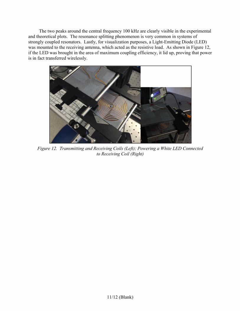
The two peaks around the central frequency 100 kHz are clearly visible in the experimental and theoretical plots. The resonance splitting phenomenon is very common in systems of strongly coupled resonators. Lastly, for visualization purposes, a Light-Emitting Diode (LED) was mounted to the receiving antenna, which acted as the resistive load. As shown in Figure 12, if the LED was brought in the area of maximum coupling efficiency, it lid up, proving that power is in fact transferred wirelessly.
Figure 12. Transmitting and Receiving Coils (Left); Powering a White LED Connected to Receiving Coil (Right)

13
REFERENCE
1. Schauber, M. J. et al., ”Measurement of mutual inductance from frequency dependence of impedance of AC coupled circuits using a digital dual-phase lock-in amplifier,” American Journal of Physics, Volume 76, 2008.

14
LIST OF ABBREVIATIONS, ACRONYMS, AND SYMBOLS
~ approximately
≈ approximately equal to
2-D Two-Dimensional
3-D Three-Dimensional
ABS acrylonitrile-butadiene-styrene
AC Alternating Current
AMRDEC Aviation and Missile Research, Development, and Engineering Center
cm centimeters
DC Direct Current
EMF Electromotive Force
FEM Finite Element Model
Hz hertz
kHz kilohertz
LC Inductor Capacitor
LED Light-Emitting Diode
m meter
MHz megahertz
mm millimeter
RLC Resistor Inductor Capacitor
S/m Siemens per meters
U.S. United States
V volt
μF microfarad
μH microhenry