Embed Size (px)
Citation preview

© January 30, 2017 Dr. Lynn Fuller, Professor
Rochester Institute of Technology
Microelectronic Engineering
Resistor MEMS
Page 1
ROCHESTER INSTITUTE OF TECHNOLOGYMICROELECTRONIC ENGINEERING
1-30-17 resistor_mems.ppt
Resistors: Heaters and Temperature
Sensors
Dr. Lynn FullerWebpage: http://people.rit.edu/lffeee
Microelectronic EngineeringRochester Institute of Technology
82 Lomb Memorial DriveRochester, NY 14623-5604
Tel (585) 475-2035Email: [email protected]
Department webpage: http://www.rit.edu/kgcoe/microelectronic/
© January 30, 2017 Dr. Lynn Fuller, Professor
Rochester Institute of Technology
Microelectronic Engineering
Resistor MEMS
Page 2
OUTLINE
Introduction
Resistors
Resistor Sensors, Light, Temperature
Heaters

© January 30, 2017 Dr. Lynn Fuller, Professor
Rochester Institute of Technology
Microelectronic Engineering
Resistor MEMS
Page 3
INTRODUCTION
Heaters are used in many MEMS applications including ink jet
print heads, actuators, bio-mems, chemical detectors and gas
flow sensors. Resistors are used in temperature sensors, strain
sensors and light sensors. This module will discuss the resistor
as a sensor and as a heater.
© January 30, 2017 Dr. Lynn Fuller, Professor
Rochester Institute of Technology
Microelectronic Engineering
Resistor MEMS
Page 4
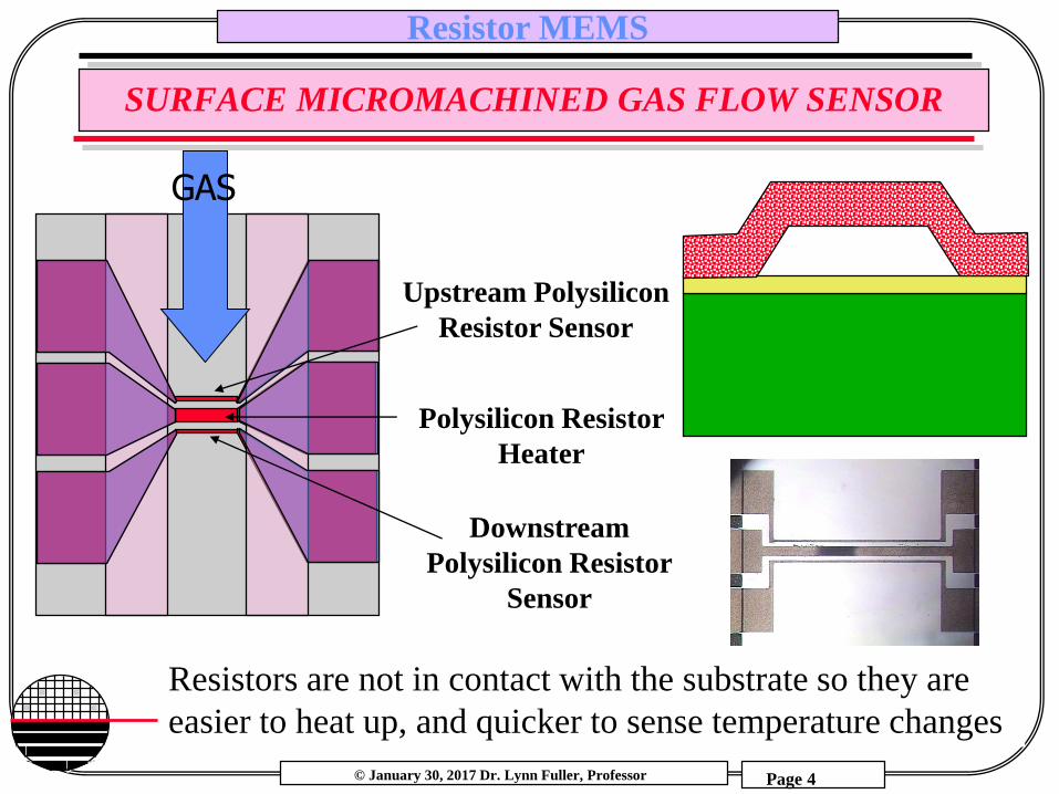
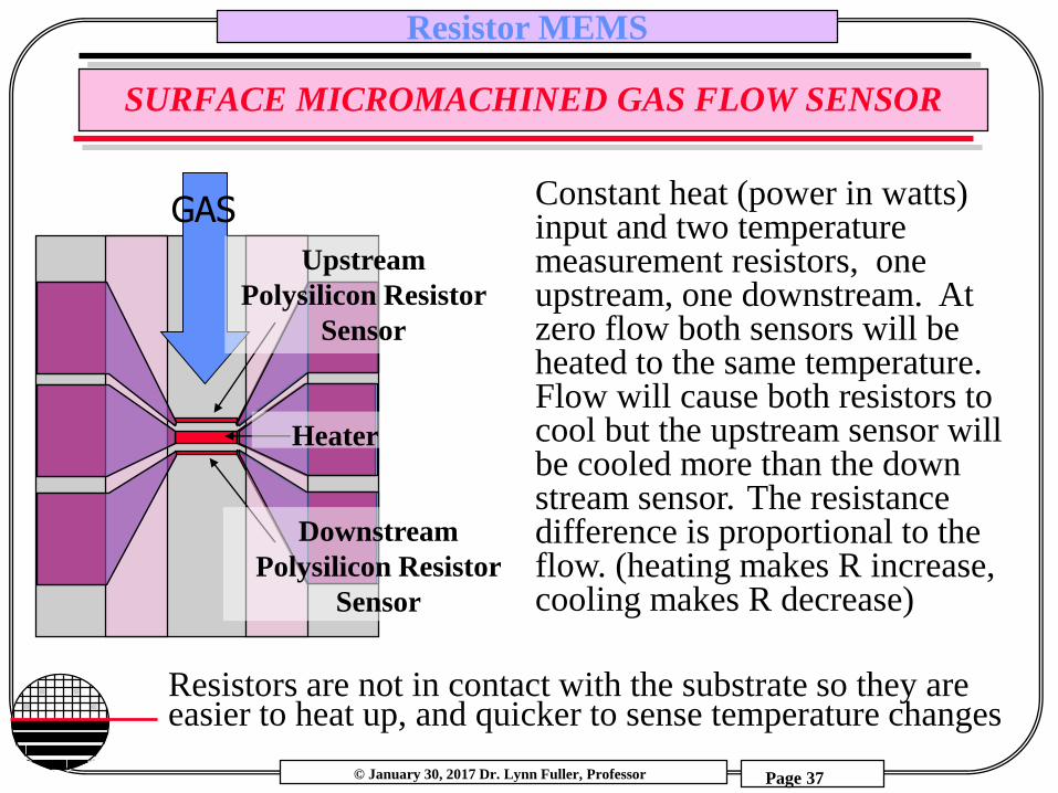
SURFACE MICROMACHINED GAS FLOW SENSOR
Upstream Polysilicon
Resistor Sensor
Polysilicon Resistor
Heater
Downstream
Polysilicon Resistor
Sensor
GAS
Resistors are not in contact with the substrate so they are
easier to heat up, and quicker to sense temperature changes
© January 30, 2017 Dr. Lynn Fuller, Professor
Rochester Institute of Technology
Microelectronic Engineering
Resistor MEMS
Page 5
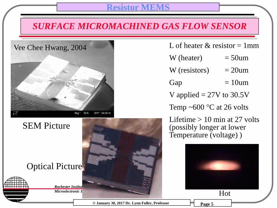
SURFACE MICROMACHINED GAS FLOW SENSOR
L of heater & resistor = 1mm
W (heater) = 50um
W (resistors) = 20um
Gap = 10um
V applied = 27V to 30.5V
Temp ~600 °C at 26 volts
Lifetime > 10 min at 27 volts (possibly longer at lower Temperature (voltage) )
Vee Chee Hwang, 2004
SEM Picture
Optical Picture
Hot
© January 30, 2017 Dr. Lynn Fuller, Professor
Rochester Institute of Technology
Microelectronic Engineering
Resistor MEMS
Page 6
OHM’S LAW
I
V
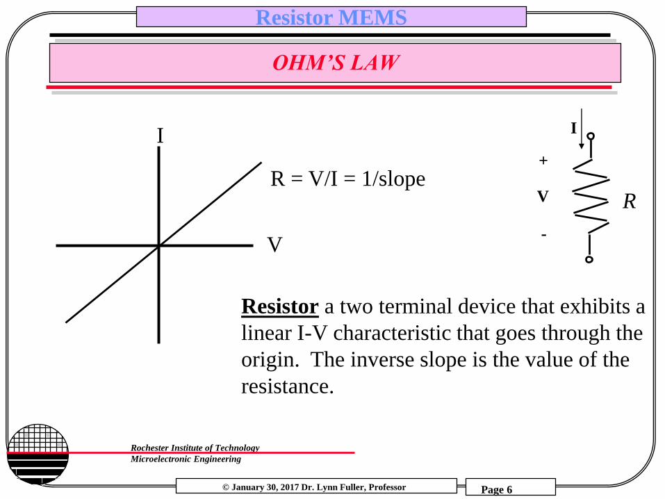
Resistor a two terminal device that exhibits a
linear I-V characteristic that goes through the
origin. The inverse slope is the value of the
resistance.
R = V/I = 1/slope
I
V
-
+
R
© January 30, 2017 Dr. Lynn Fuller, Professor
Rochester Institute of Technology
Microelectronic Engineering
Resistor MEMS
Page 7
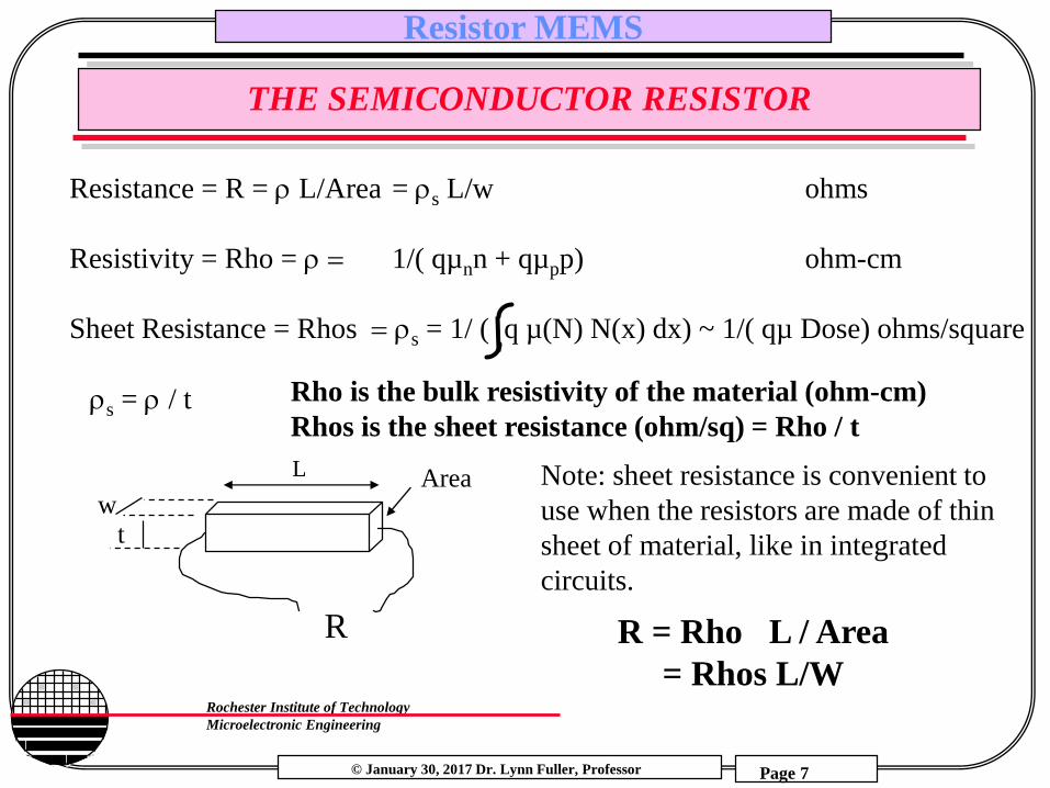
THE SEMICONDUCTOR RESISTOR
Resistance = R = L/Area = s L/w ohms
Resistivity = Rho = 1/( qµnn + qµpp) ohm-cm
Sheet Resistance = Rhos s = 1/ ( q µ(N) N(x) dx) ~ 1/( qµ Dose) ohms/square
L Area
R
wt
s = / t
Note: sheet resistance is convenient to
use when the resistors are made of thin
sheet of material, like in integrated
circuits.
R = Rho L / Area
= Rhos L/W
Rho is the bulk resistivity of the material (ohm-cm)
Rhos is the sheet resistance (ohm/sq) = Rho / t

© January 30, 2017 Dr. Lynn Fuller, Professor
Rochester Institute of Technology
Microelectronic Engineering
Resistor MEMS
Page 8
MOBILITY
Total Impurity Concentration (cm-3)
0
2 0 0
4 0 0
6 0 0
8 0 0
1 0 0 0
1 2 0 0
1 4 0 0
1 0 ^ 1 3 1 0 ^ 1 5 1 0 ^ 1 7 1 0 ^ 1 9
A r s e n icB o r o nP h o s p h o r u s
Mo
bil
ity (
cm2/
V s
ec)
electrons
holes
Parameter Arsenic Phosphorous Boron
µmin 52.2 68.5 44.9
µmax 1417 1414 470.5
Nref 9.68X10^16 9.20X10^16 2.23X10^17
0.680 0.711 0.719
µ(N) = µ mi+ (µmax-µmin)
{1 + (N/Nref)}
Electron and hole mobilities in silicon at 300 K as functions of the total dopant concentration (N). The values plotted are the results of the curve fitting measurements from several sources. The mobility curves can be generated using the equation below with the parameters shown:
From Muller and Kamins, 3rd Ed., pg 33
© January 30, 2017 Dr. Lynn Fuller, Professor
Rochester Institute of Technology
Microelectronic Engineering
Resistor MEMS
Page 9
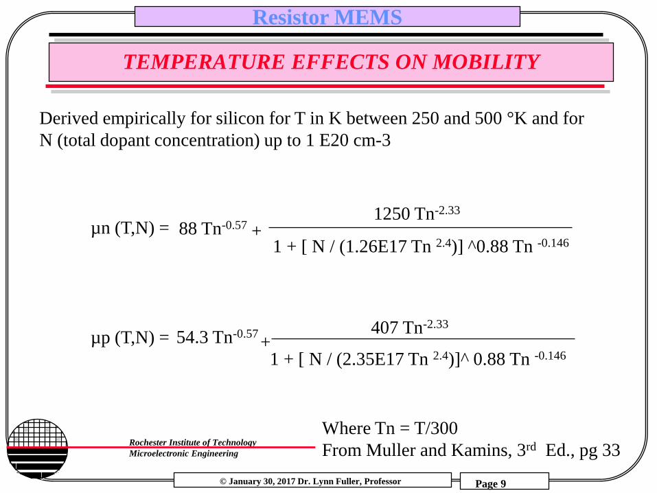
TEMPERATURE EFFECTS ON MOBILITY
Derived empirically for silicon for T in K between 250 and 500 °K and for
N (total dopant concentration) up to 1 E20 cm-3
µn (T,N) =
µp (T,N) =
88 Tn-0.57
54.3 Tn-0.57
Where Tn = T/300
From Muller and Kamins, 3rd Ed., pg 33
1250 Tn-2.33
407 Tn-2.33
1 + [ N / (1.26E17 Tn 2.4)] ^0.88 Tn -0.146
1 + [ N / (2.35E17 Tn 2.4)]^ 0.88 Tn -0.146
+
+
© January 30, 2017 Dr. Lynn Fuller, Professor
Rochester Institute of Technology
Microelectronic Engineering
Resistor MEMS
Page 10
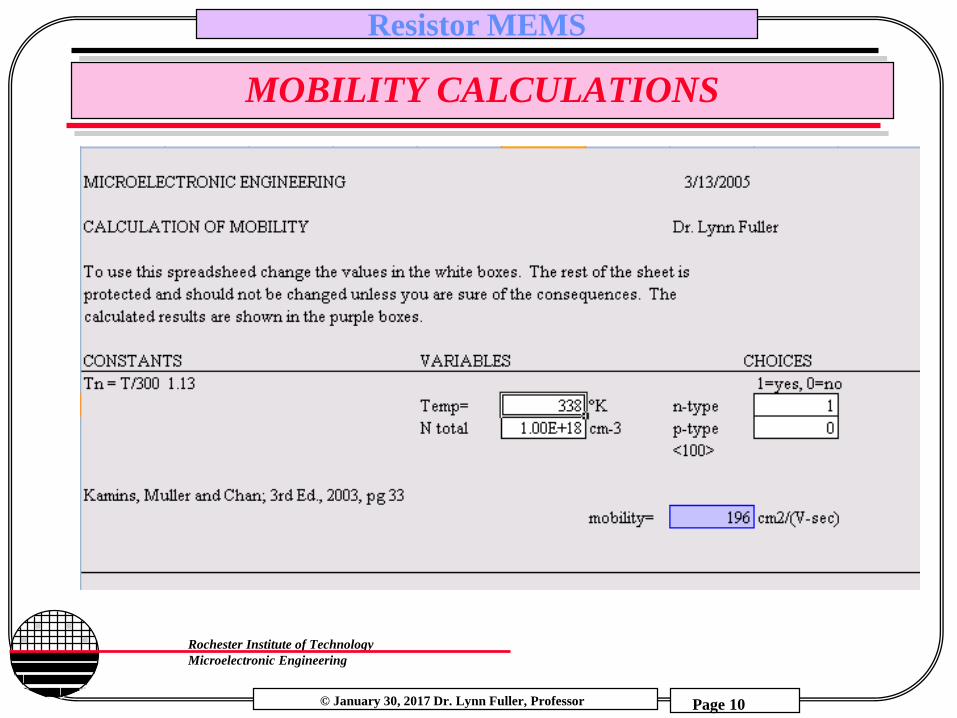
MOBILITY CALCULATIONS

© January 30, 2017 Dr. Lynn Fuller, Professor
Rochester Institute of Technology
Microelectronic Engineering
Resistor MEMS
Page 11
TEMPERATURE COEFFICIENT OF RESISTANCE
R/T for semiconductor resistors
R = Rhos L/W = Rho/t L/W
assume W, L, t do not change with T
Rho = 1/(qµn + qµp) where µ is the mobility which is a function of temperature, n and p are the carrier concentrations which can be a function of temperature (in lightly doped semiconductors)
as T increases, µ decreases, n or p may increase and the result is that R usually increases unless the decrease in µ is cancelled by the increase in n or p
© January 30, 2017 Dr. Lynn Fuller, Professor
Rochester Institute of Technology
Microelectronic Engineering
Resistor MEMS
Page 12
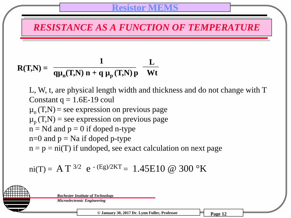
RESISTANCE AS A FUNCTION OF TEMPERATURE
R(T,N) = 1
qµn(T,N) n + q µp (T,N) p
L
Wt
L, W, t, are physical length width and thickness and do not change with T
Constant q = 1.6E-19 coul
µn (T,N) = see expression on previous page
µp (T,N) = see expression on previous page
n = Nd and p = 0 if doped n-type
n=0 and p = Na if doped p-type
n = p = ni(T) if undoped, see exact calculation on next page
ni(T) = A T 3/2 e - (Eg)/2KT = 1.45E10 @ 300 °K
© January 30, 2017 Dr. Lynn Fuller, Professor
Rochester Institute of Technology
Microelectronic Engineering
Resistor MEMS
Page 13
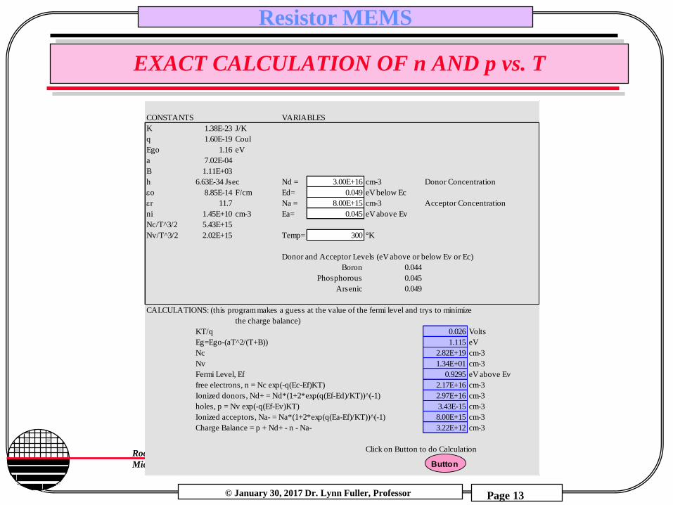
EXACT CALCULATION OF n AND p vs. T
CONSTANTS VARIABLES
K 1.38E-23 J/K
q 1.60E-19 Coul
Ego 1.16 eV
a 7.02E-04
B 1.11E+03
h 6.63E-34 Jsec Nd = 3.00E+16 cm-3 Donor Concentration
eo 8.85E-14 F/cm Ed= 0.049 eV below Ec
er 11.7 Na = 8.00E+15 cm-3 Acceptor Concentration
ni 1.45E+10 cm-3 Ea= 0.045 eV above Ev
Nc/T^3/2 5.43E+15
Nv/T^3/2 2.02E+15 Temp= 300 °K
Donor and Acceptor Levels (eV above or below Ev or Ec)
Boron 0.044
Phosphorous 0.045
Arsenic 0.049
CALCULATIONS: (this program makes a guess at the value of the fermi level and trys to minimize
the charge balance)
KT/q 0.026 Volts
Eg=Ego-(aT^2/(T+B)) 1.115 eV
Nc 2.82E+19 cm-3
Nv 1.34E+01 cm-3
Fermi Level, Ef 0.9295 eV above Ev
free electrons, n = Nc exp(-q(Ec-Ef)KT) 2.17E+16 cm-3
Ionized donors, Nd+ = Nd*(1+2*exp(q(Ef-Ed)/KT))^(-1) 2.97E+16 cm-3
holes, p = Nv exp(-q(Ef-Ev)KT) 3.43E-15 cm-3
Ionized acceptors, Na- = Na*(1+2*exp(q(Ea-Ef)/KT))^(-1) 8.00E+15 cm-3
Charge Balance = p + Nd+ - n - Na- 3.22E+12 cm-3
Click on Button to do Calculation
Button
Button
© January 30, 2017 Dr. Lynn Fuller, Professor
Rochester Institute of Technology
Microelectronic Engineering
Resistor MEMS
Page 14
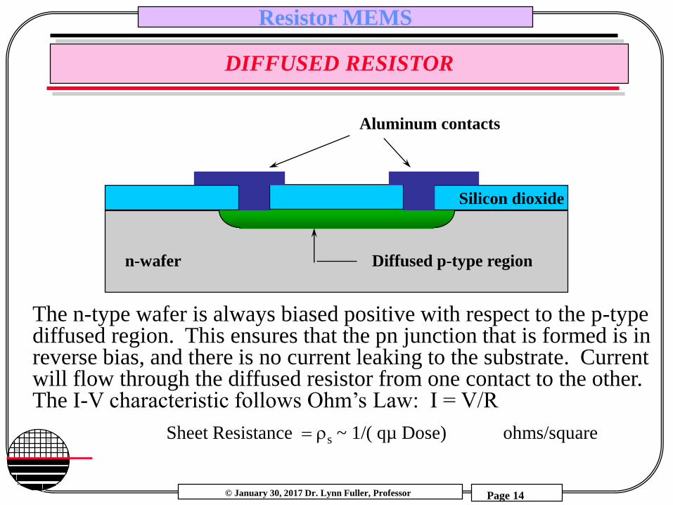
DIFFUSED RESISTOR
Aluminum contacts
The n-type wafer is always biased positive with respect to the p-type diffused region. This ensures that the pn junction that is formed is in reverse bias, and there is no current leaking to the substrate. Current will flow through the diffused resistor from one contact to the other. The I-V characteristic follows Ohm’s Law: I = V/R
n-wafer Diffused p-type region
Silicon dioxide
Sheet Resistance s ~ 1/( qµ Dose) ohms/square
© January 30, 2017 Dr. Lynn Fuller, Professor
Rochester Institute of Technology
Microelectronic Engineering
Resistor MEMS
Page 15
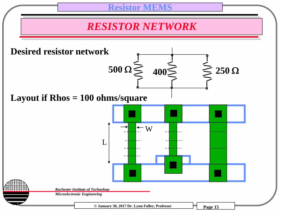
RESISTOR NETWORK
500 W 400 250 W
Desired resistor network
Layout if Rhos = 100 ohms/square
L
W
© January 30, 2017 Dr. Lynn Fuller, Professor
Rochester Institute of Technology
Microelectronic Engineering
Resistor MEMS
Page 16
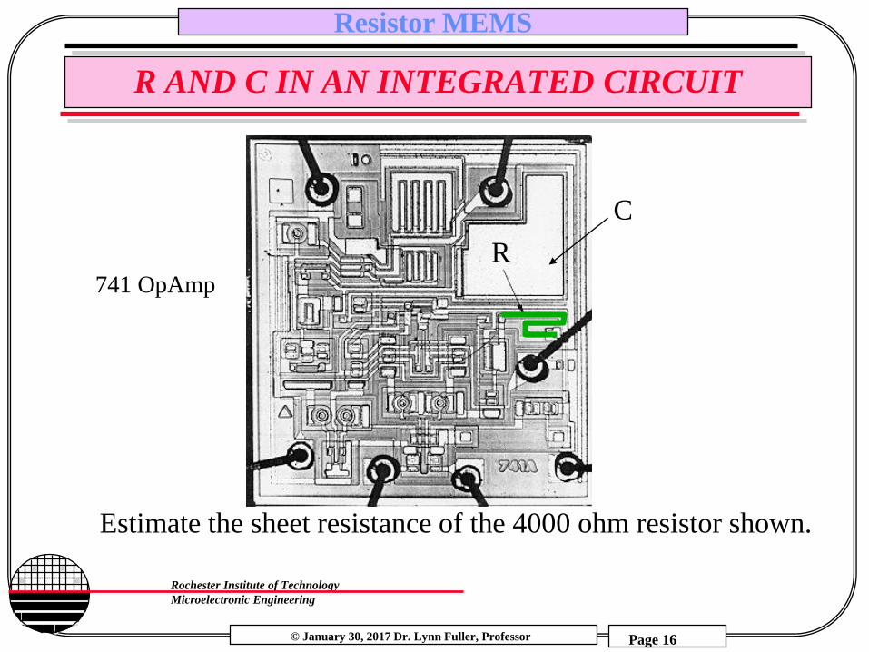
R AND C IN AN INTEGRATED CIRCUIT
Estimate the sheet resistance of the 4000 ohm resistor shown.
R
C
741 OpAmp

© January 30, 2017 Dr. Lynn Fuller, Professor
Rochester Institute of Technology
Microelectronic Engineering
Resistor MEMS
Page 17
DIFFUSION FROM A CONSTANT SOURCE
N(x,t) = No erfc (x/2 Dptp)
SolidSolubilityLimit, No
x
into wafer
Wafer Background Concentration, NBC
N(x,t)
Xj
p-type
n-type
erfc function
for erfc predeposit
Q’A (tp) = QA(tp)/Area = 2 No (Dptp) / Dose
Where Dp is the diffusion constant at the predeposit temperature and tp is the predeposit time
© January 30, 2017 Dr. Lynn Fuller, Professor
Rochester Institute of Technology
Microelectronic Engineering
Resistor MEMS
Page 18
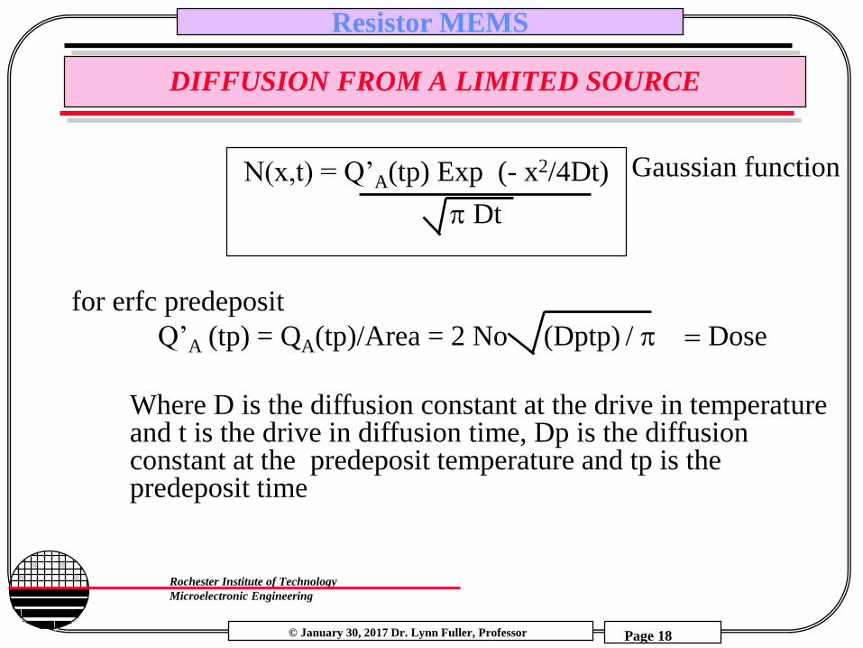
DIFFUSION FROM A LIMITED SOURCE
for erfc predeposit
Q’A (tp) = QA(tp)/Area = 2 No (Dptp) / Dose
N(x,t) = Q’A(tp) Exp (- x2/4Dt)
Dt
Where D is the diffusion constant at the drive in temperature and t is the drive in diffusion time, Dp is the diffusion constant at the predeposit temperature and tp is the predeposit time
Gaussian function
© January 30, 2017 Dr. Lynn Fuller, Professor
Rochester Institute of Technology
Microelectronic Engineering
Resistor MEMS
Page 19
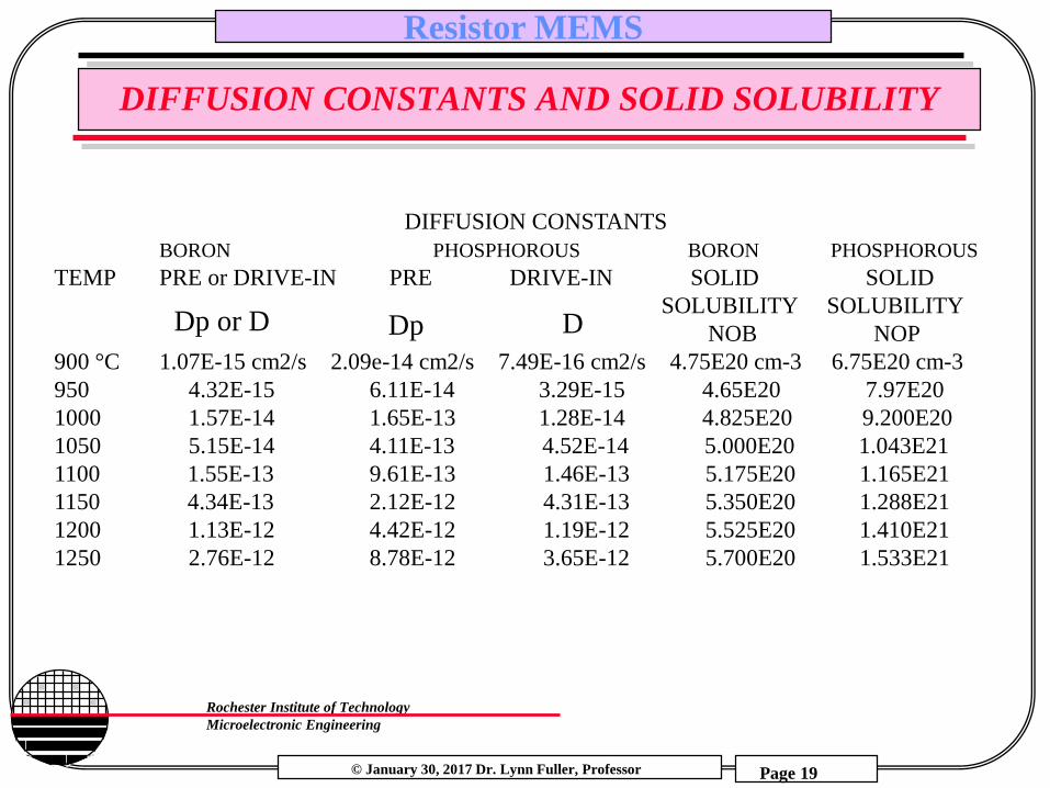
DIFFUSION CONSTANTS AND SOLID SOLUBILITY
DIFFUSION CONSTANTS
BORON PHOSPHOROUS BORON PHOSPHOROUS
TEMP PRE or DRIVE-IN PRE DRIVE-IN SOLID SOLID
SOLUBILITY SOLUBILITY
NOB NOP
900 °C 1.07E-15 cm2/s 2.09e-14 cm2/s 7.49E-16 cm2/s 4.75E20 cm-3 6.75E20 cm-3
950 4.32E-15 6.11E-14 3.29E-15 4.65E20 7.97E20
1000 1.57E-14 1.65E-13 1.28E-14 4.825E20 9.200E20
1050 5.15E-14 4.11E-13 4.52E-14 5.000E20 1.043E21
1100 1.55E-13 9.61E-13 1.46E-13 5.175E20 1.165E21
1150 4.34E-13 2.12E-12 4.31E-13 5.350E20 1.288E21
1200 1.13E-12 4.42E-12 1.19E-12 5.525E20 1.410E21
1250 2.76E-12 8.78E-12 3.65E-12 5.700E20 1.533E21
DpDp or D D
© January 30, 2017 Dr. Lynn Fuller, Professor
Rochester Institute of Technology
Microelectronic Engineering
Resistor MEMS
Page 20
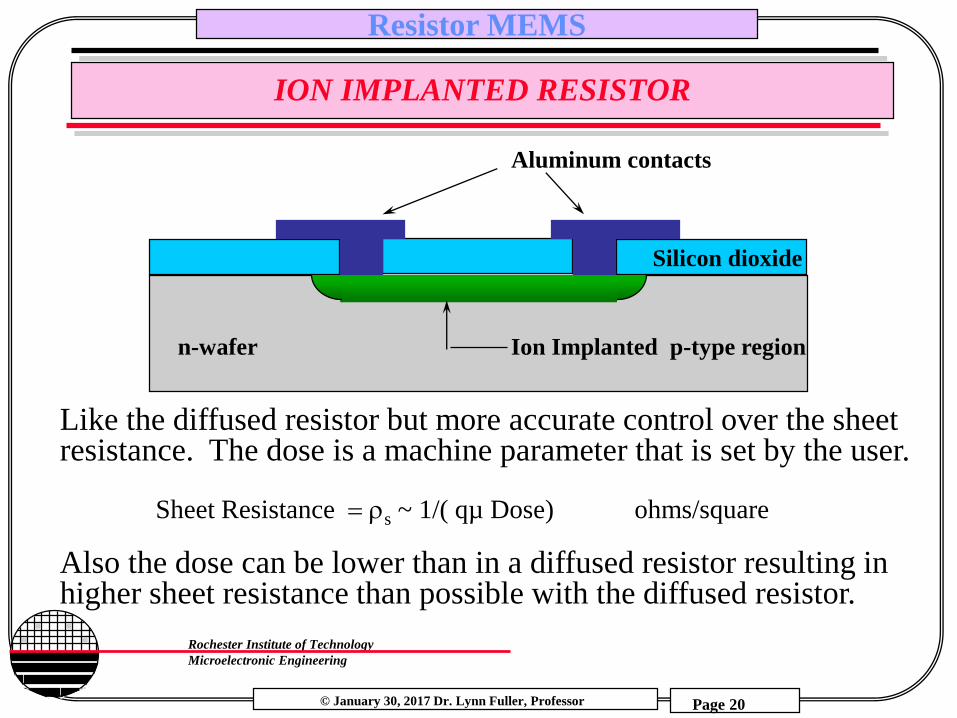
ION IMPLANTED RESISTOR
Like the diffused resistor but more accurate control over the sheet resistance. The dose is a machine parameter that is set by the user.
Sheet Resistance s ~ 1/( qµ Dose) ohms/square
Also the dose can be lower than in a diffused resistor resulting in higher sheet resistance than possible with the diffused resistor.
Aluminum contacts
n-wafer Ion Implanted p-type region
Silicon dioxide
© January 30, 2017 Dr. Lynn Fuller, Professor
Rochester Institute of Technology
Microelectronic Engineering
Resistor MEMS
Page 21
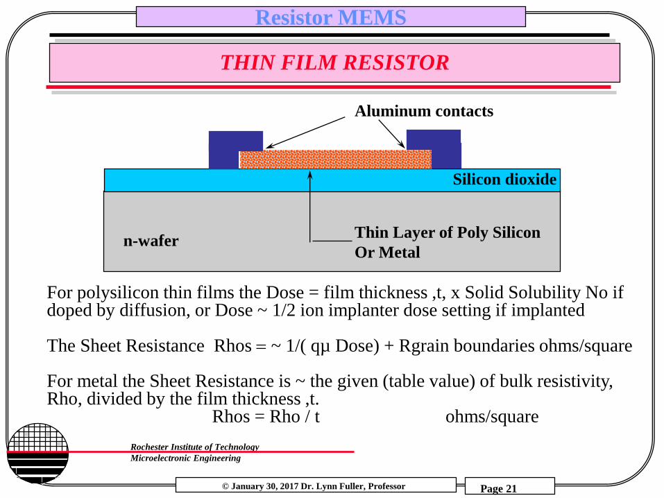
THIN FILM RESISTOR
Aluminum contacts
n-waferThin Layer of Poly Silicon
Or Metal
Silicon dioxide
For polysilicon thin films the Dose = film thickness ,t, x Solid Solubility No if doped by diffusion, or Dose ~ 1/2 ion implanter dose setting if implanted
The Sheet Resistance Rhos ~ 1/( qµ Dose) + Rgrain boundaries ohms/square
For metal the Sheet Resistance is ~ the given (table value) of bulk resistivity, Rho, divided by the film thickness ,t.
Rhos = Rho / t ohms/square
© January 30, 2017 Dr. Lynn Fuller, Professor
Rochester Institute of Technology
Microelectronic Engineering
Resistor MEMS
Page 22
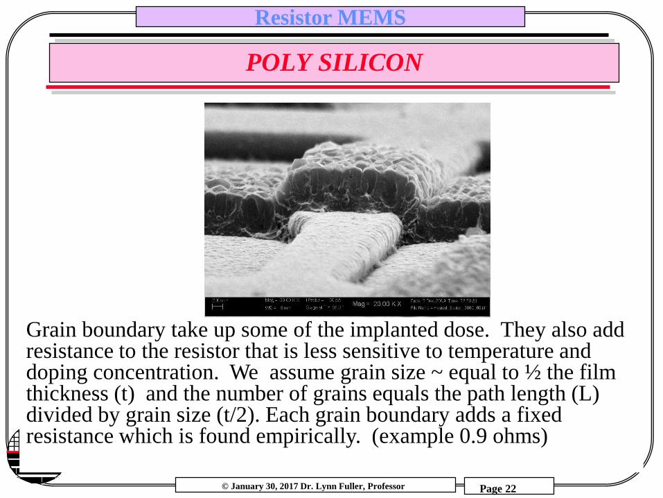
POLY SILICON
Grain boundary take up some of the implanted dose. They also add resistance to the resistor that is less sensitive to temperature and doping concentration. We assume grain size ~ equal to ½ the film thickness (t) and the number of grains equals the path length (L) divided by grain size (t/2). Each grain boundary adds a fixed resistance which is found empirically. (example 0.9 ohms)
© January 30, 2017 Dr. Lynn Fuller, Professor
Rochester Institute of Technology
Microelectronic Engineering
Resistor MEMS
Page 23
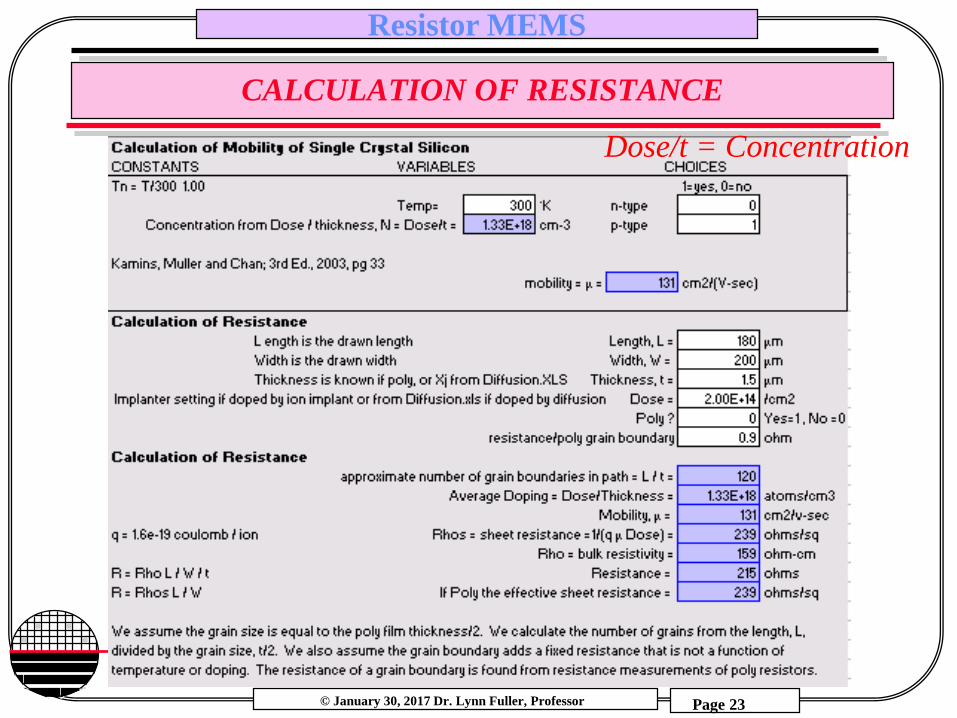
CALCULATION OF RESISTANCE
Dose/t = Concentration

© January 30, 2017 Dr. Lynn Fuller, Professor
Rochester Institute of Technology
Microelectronic Engineering
Resistor MEMS
Page 24
RESISTOR I-V CHARACTERISTICS
R= 1/1.44e-3
= 694 ohms
Use t=1.5, L=500, w=100 dose =0.5e15, p-type single crystal silicon
© January 30, 2017 Dr. Lynn Fuller, Professor
Rochester Institute of Technology
Microelectronic Engineering
Resistor MEMS
Page 25
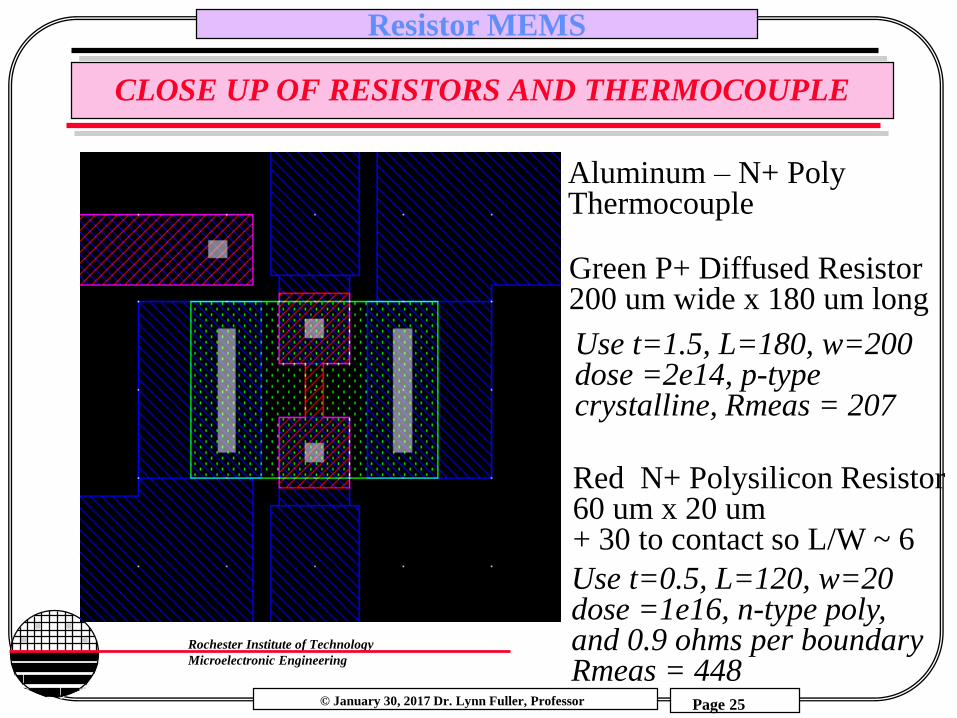
CLOSE UP OF RESISTORS AND THERMOCOUPLE
Red N+ Polysilicon Resistor60 um x 20 um + 30 to contact so L/W ~ 6
Green P+ Diffused Resistor200 um wide x 180 um long
Aluminum – N+ PolyThermocouple
Use t=0.5, L=120, w=20 dose =1e16, n-type poly, and 0.9 ohms per boundaryRmeas = 448
Use t=1.5, L=180, w=200 dose =2e14, p-type crystalline, Rmeas = 207
© January 30, 2017 Dr. Lynn Fuller, Professor
Rochester Institute of Technology
Microelectronic Engineering
Resistor MEMS
Page 26
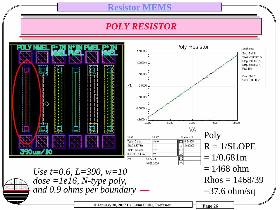
POLY RESISTOR
Poly
R = 1/SLOPE
= 1/0.681m
= 1468 ohm
Rhos = 1468/39
=37.6 ohm/sq
Use t=0.6, L=390, w=10 dose =1e16, N-type poly, and 0.9 ohms per boundary
© January 30, 2017 Dr. Lynn Fuller, Professor
Rochester Institute of Technology
Microelectronic Engineering
Resistor MEMS
Page 27
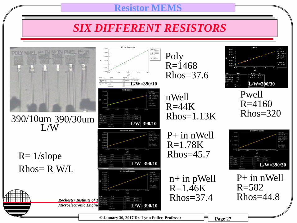
SIX DIFFERENT RESISTORS
390/30um390/10um
R= 1/slope
Rhos= R W/L
L/W
PolyR=1468Rhos=37.6
nWellR=44K Rhos=1.13K
P+ in nWellR=1.78K Rhos=45.7
n+ in pWellR=1.46K Rhos=37.4
L/W=390/10
L/W=390/10
L/W=390/10
PwellR=4160Rhos=320
P+ in nWellR=582Rhos=44.8
L/W=390/30
L/W=390/30L/W=390/10
© January 30, 2017 Dr. Lynn Fuller, Professor
Rochester Institute of Technology
Microelectronic Engineering
Resistor MEMS
Page 28
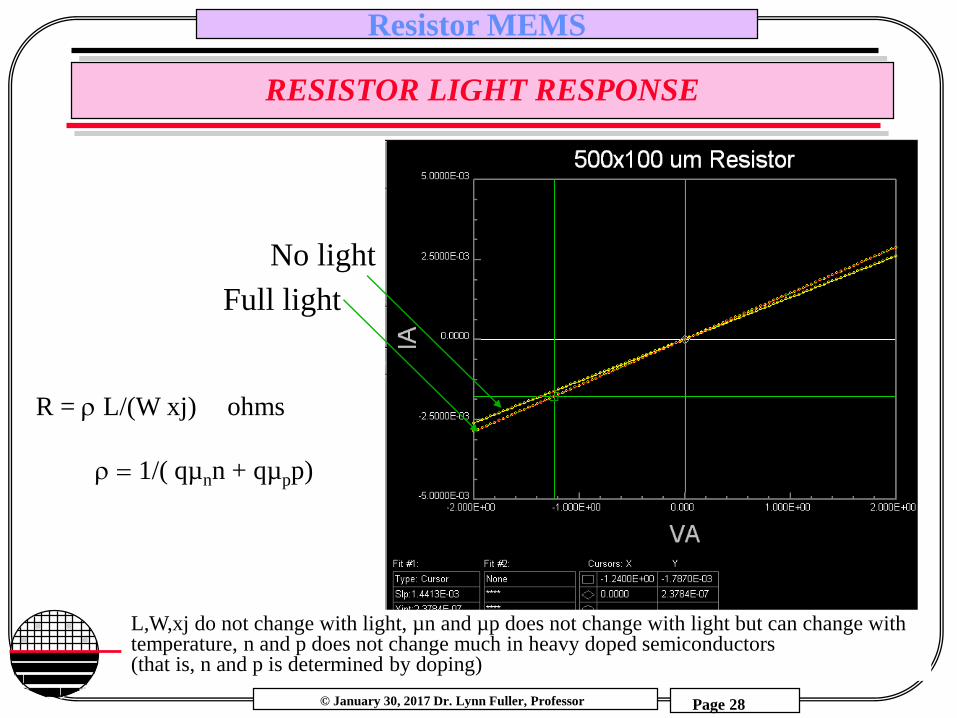
RESISTOR LIGHT RESPONSE
No light
Full light
R = L/(W xj) ohms
1/( qµnn + qµpp)
L,W,xj do not change with light, µn and µp does not change with light but can change with temperature, n and p does not change much in heavy doped semiconductors (that is, n and p is determined by doping)
© January 30, 2017 Dr. Lynn Fuller, Professor
Rochester Institute of Technology
Microelectronic Engineering
Resistor MEMS
Page 29
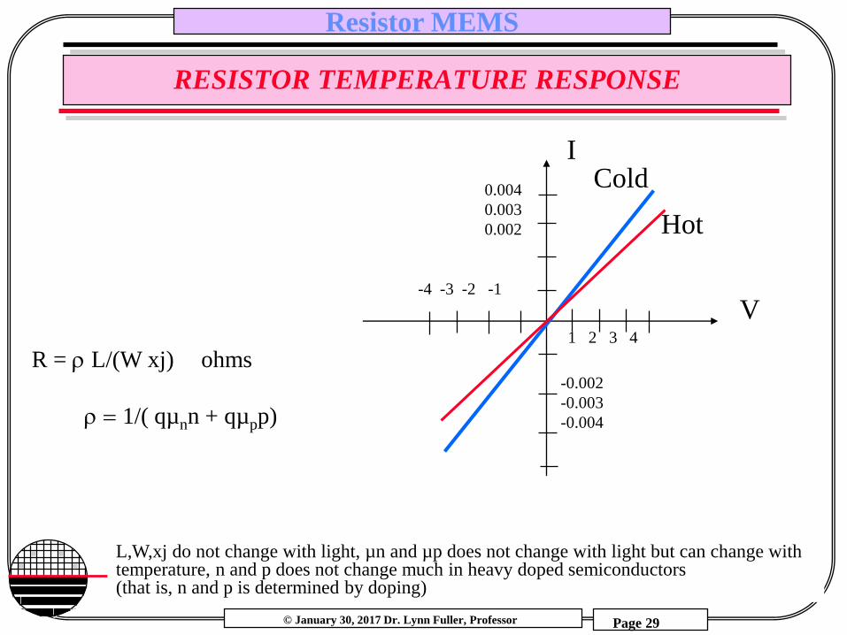
RESISTOR TEMPERATURE RESPONSE
I
V1 2 3 4
-4 -3 -2 -1
-0.002
-0.003
-0.004
0.004
0.003
0.002
Cold
Hot
L,W,xj do not change with light, µn and µp does not change with light but can change with temperature, n and p does not change much in heavy doped semiconductors (that is, n and p is determined by doping)
R = L/(W xj) ohms
1/( qµnn + qµpp)
© January 30, 2017 Dr. Lynn Fuller, Professor
Rochester Institute of Technology
Microelectronic Engineering
Resistor MEMS
Page 30
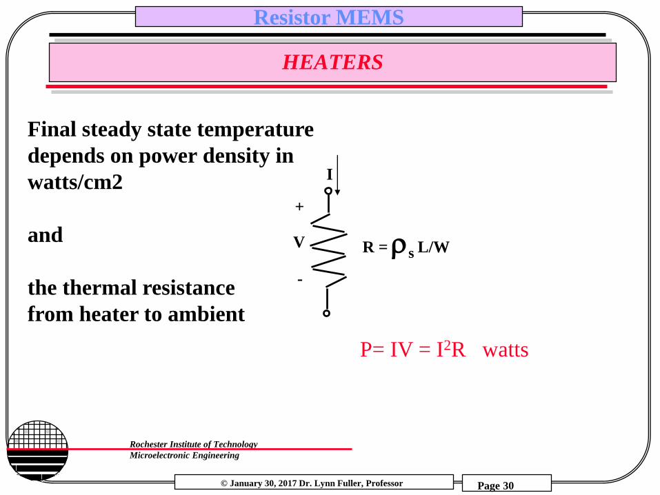
HEATERS
P= IV = I2R watts
Final steady state temperature
depends on power density in
watts/cm2
and
the thermal resistance
from heater to ambient
I
V
-
+
R = s L/W
© January 30, 2017 Dr. Lynn Fuller, Professor
Rochester Institute of Technology
Microelectronic Engineering
Resistor MEMS
Page 31
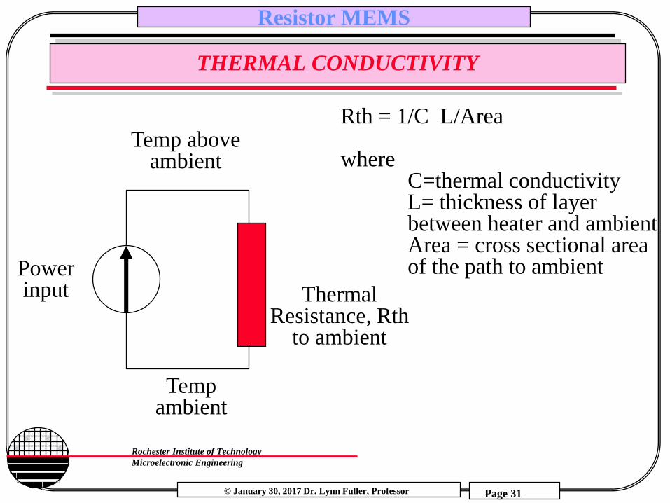
THERMAL CONDUCTIVITY
Tempambient
ThermalResistance, Rth
to ambient
Temp aboveambient
Powerinput
Rth = 1/C L/Area
whereC=thermal conductivityL= thickness of layer between heater and ambientArea = cross sectional areaof the path to ambient
© January 30, 2017 Dr. Lynn Fuller, Professor
Rochester Institute of Technology
Microelectronic Engineering
Resistor MEMS
Page 32
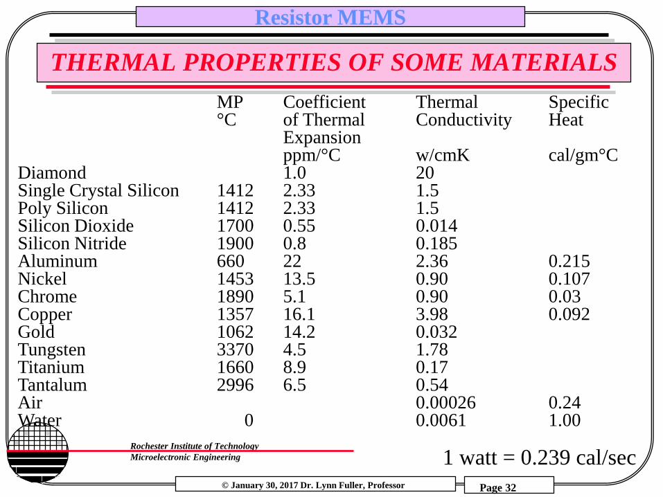
THERMAL PROPERTIES OF SOME MATERIALS
MP Coefficient Thermal Specific°C of Thermal Conductivity Heat
Expansionppm/°C w/cmK cal/gm°C
Diamond 1.0 20Single Crystal Silicon 1412 2.33 1.5Poly Silicon 1412 2.33 1.5Silicon Dioxide 1700 0.55 0.014Silicon Nitride 1900 0.8 0.185Aluminum 660 22 2.36 0.215Nickel 1453 13.5 0.90 0.107Chrome 1890 5.1 0.90 0.03Copper 1357 16.1 3.98 0.092Gold 1062 14.2 0.032Tungsten 3370 4.5 1.78Titanium 1660 8.9 0.17Tantalum 2996 6.5 0.54Air 0.00026 0.24Water 0 0.0061 1.00
1 watt = 0.239 cal/sec

© January 30, 2017 Dr. Lynn Fuller, Professor
Rochester Institute of Technology
Microelectronic Engineering
Resistor MEMS
Page 33
HEATER EXAMPLE
Example: Poly heater 100x100µm has sheet resistance of 25 ohms/sq and 9 volts is applied. What temperature will it reach if built on 1 µm thick oxide?
Power = V2/R = 81/25 = 3.24 watt
Rthermal = 1/C L/Area = (1/0.014 watt/cm °C)(1e-4cm/(100e-4cm x100e-4cm))
= 71.4 °C/watt
Temperature = Tambient + (3.24) (71.4) = Tambient + 231 °C
© January 30, 2017 Dr. Lynn Fuller, Professor
Rochester Institute of Technology
Microelectronic Engineering
Resistor MEMS
Page 34
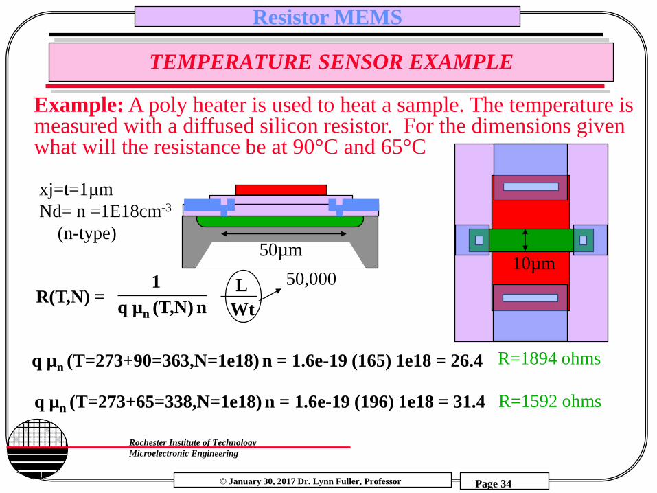
TEMPERATURE SENSOR EXAMPLE
Example: A poly heater is used to heat a sample. The temperature is measured with a diffused silicon resistor. For the dimensions given what will the resistance be at 90°C and 65°C
R(T,N) = 1
q µn (T,N) n
L
Wt
50µm10µm
xj=t=1µm
Nd= n =1E18cm-3
(n-type)
q µn (T=273+65=338,N=1e18) n = 1.6e-19 (196) 1e18 = 31.4
q µn (T=273+90=363,N=1e18) n = 1.6e-19 (165) 1e18 = 26.4
50,000
R=1894 ohms
R=1592 ohms
© January 30, 2017 Dr. Lynn Fuller, Professor
Rochester Institute of Technology
Microelectronic Engineering
Resistor MEMS
Page 35
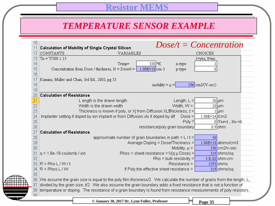
TEMPERATURE SENSOR EXAMPLE
Dose/t = Concentration

© January 30, 2017 Dr. Lynn Fuller, Professor
Rochester Institute of Technology
Microelectronic Engineering
Resistor MEMS
Page 36
DIODES AND HEATERS
Poly Heater on top of Diodes
Integrated n-well series resistor.
VDD
Vo ~ .7
-2.2mV/°C
I
V
T1T2
T2>T1
I ~ (VDD-.7)/R
R
© January 30, 2017 Dr. Lynn Fuller, Professor
Rochester Institute of Technology
Microelectronic Engineering
Resistor MEMS
Page 37
SURFACE MICROMACHINED GAS FLOW SENSOR
GAS
Resistors are not in contact with the substrate so they are easier to heat up, and quicker to sense temperature changes
Constant heat (power in watts) input and two temperature measurement resistors, one upstream, one downstream. At zero flow both sensors will be heated to the same temperature. Flow will cause both resistors to cool but the upstream sensor will be cooled more than the down stream sensor. The resistance difference is proportional to the flow. (heating makes R increase, cooling makes R decrease)
Downstream
Polysilicon Resistor
Sensor
Heater
Upstream
Polysilicon Resistor
Sensor
© January 30, 2017 Dr. Lynn Fuller, Professor
Rochester Institute of Technology
Microelectronic Engineering
Resistor MEMS
Page 38
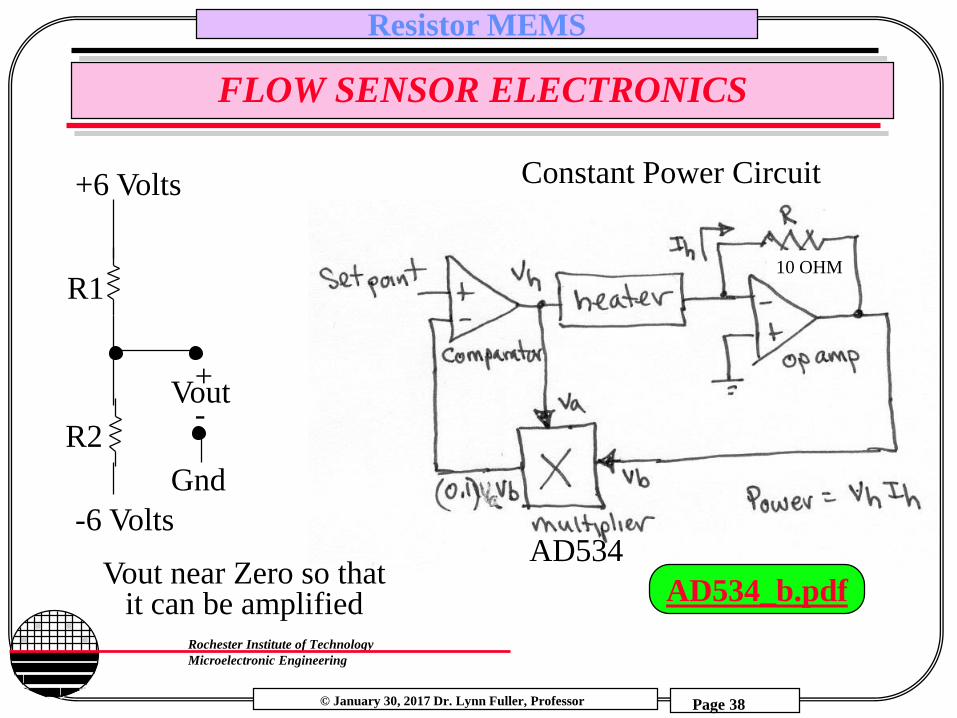
FLOW SENSOR ELECTRONICS
Gnd
+6 Volts
-6 Volts
Vout+
-
Constant Power Circuit
Vout near Zero so thatit can be amplified
R1
R2
AD534
10 OHM
AD534_b.pdf
© January 30, 2017 Dr. Lynn Fuller, Professor
Rochester Institute of Technology
Microelectronic Engineering
Resistor MEMS
Page 39
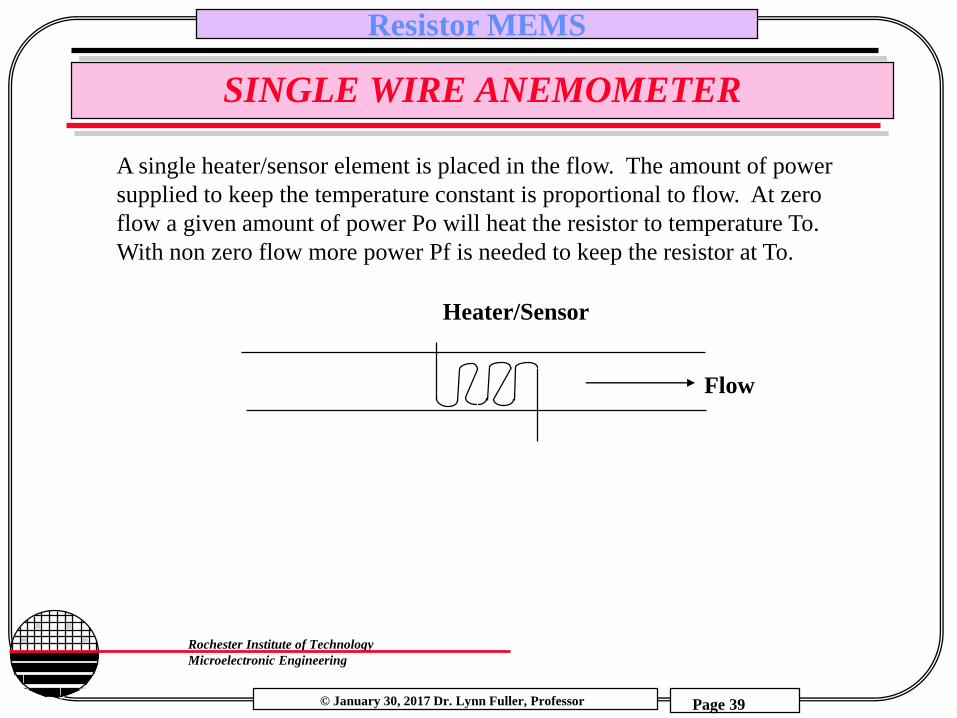
SINGLE WIRE ANEMOMETER
A single heater/sensor element is placed in the flow. The amount of power
supplied to keep the temperature constant is proportional to flow. At zero
flow a given amount of power Po will heat the resistor to temperature To.
With non zero flow more power Pf is needed to keep the resistor at To.
Flow
Heater/Sensor
© January 30, 2017 Dr. Lynn Fuller, Professor
Rochester Institute of Technology
Microelectronic Engineering
Resistor MEMS
Page 40
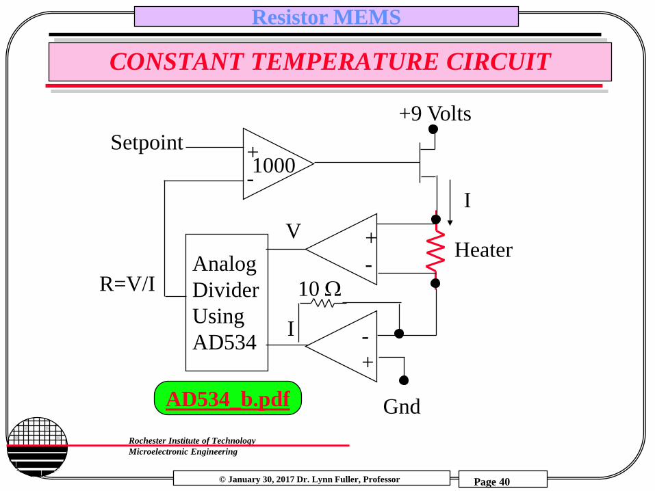
CONSTANT TEMPERATURE CIRCUIT
Analog
Divider
Using
AD534
Gnd
+9 Volts
I
Setpoint
+
-Heater
10 W
-
+
+
-
R=V/I
I
V
1000
AD534_b.pdf
© January 30, 2017 Dr. Lynn Fuller, Professor
Rochester Institute of Technology
Microelectronic Engineering
Resistor MEMS
Page 41
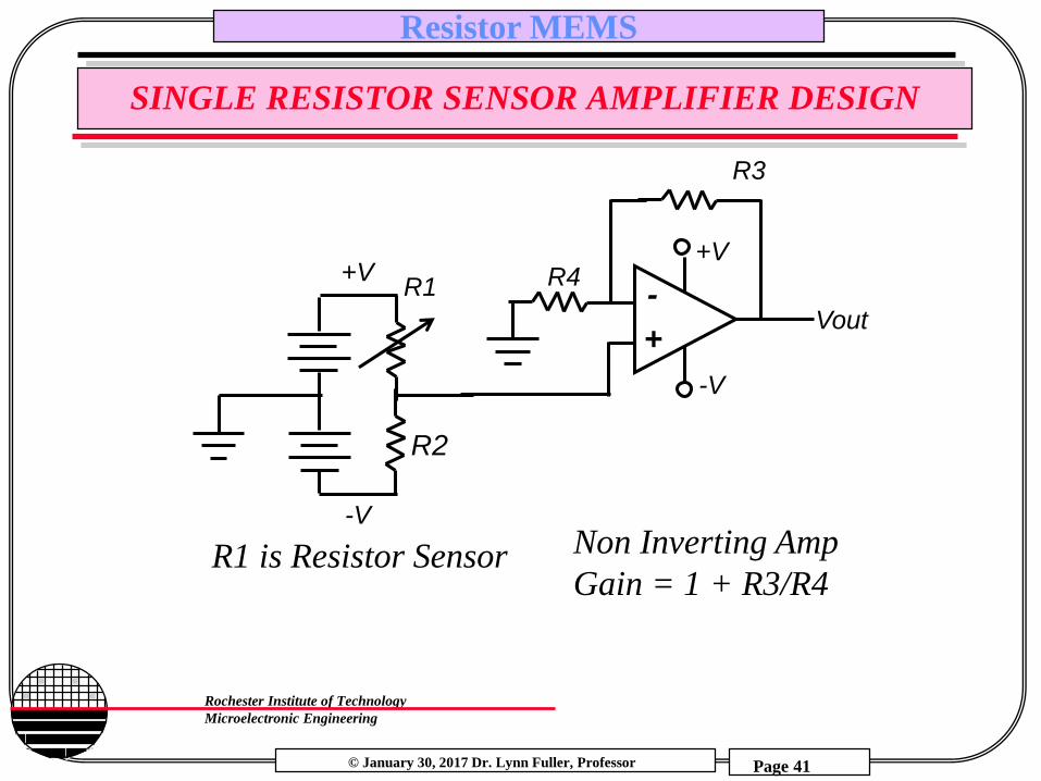
SINGLE RESISTOR SENSOR AMPLIFIER DESIGN
-
+
+V
-V
R4
Vout
-V
R1+V
R2
R3
Non Inverting Amp
Gain = 1 + R3/R4R1 is Resistor Sensor
© January 30, 2017 Dr. Lynn Fuller, Professor
Rochester Institute of Technology
Microelectronic Engineering
Resistor MEMS
Page 42
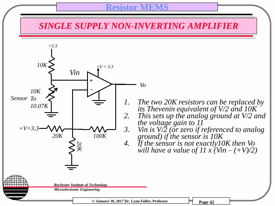
SINGLE SUPPLY NON-INVERTING AMPLIFIER
-
+
20K
+V = 3.3
20
K
+V=3.3
100K
+3.3
10K
To
10.07K
10K
Sensor
Vo
1. The two 20K resistors can be replaced by its Thevenin equivalent of V/2 and 10K
2. This sets up the analog ground at V/2 and the voltage gain to 11
3. Vin is V/2 (or zero if referenced to analog ground) if the sensor is 10K
4. If the sensor is not exactly10K then Vo will have a value of 11 x (Vin – (+V)/2)
Vin
© January 30, 2017 Dr. Lynn Fuller, Professor
Rochester Institute of Technology
Microelectronic Engineering
Resistor MEMS
Page 43
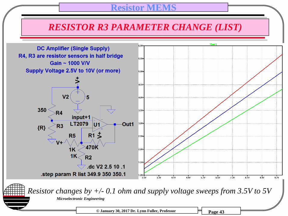
RESISTOR R3 PARAMETER CHANGE (LIST)
Resistor changes by +/- 0.1 ohm and supply voltage sweeps from 3.5V to 5V
© January 30, 2017 Dr. Lynn Fuller, Professor
Rochester Institute of Technology
Microelectronic Engineering
Resistor MEMS
Page 44
REFERENCES
1. Mechanics of Materials, by Ferdinand P. Beer, E. Russell
Johnston, Jr., McGraw-Hill Book Co.1981, ISBN 0-07-004284-5
2. Electromagnetics, by John D Kraus, Keith R. Carver, McGraw-
Hill Book Co.1981, ISBN 0-07-035396-4
3. Fundamentals of Microfabrication, M. Madou, CRC Press, New
York, 19974. Mechanics of Materials, by Ferdinand P. Beer, E. Russell
Johnston, Jr., McGraw-Hill Book Co.1981, ISBN 0-07-004284-55. Device Electronics for Integrated Circuits, Richard S. Muller,
Theodore I. Kamins, John Wiley & Sons., 3rd edition, 2003.

© January 30, 2017 Dr. Lynn Fuller, Professor
Rochester Institute of Technology
Microelectronic Engineering
Resistor MEMS
Page 45
HOMEWORK – RESISTORS
1. Poly heater is 500 µm long and 100µm wide, it has a sheet resistance of 25 ohms/sq and 9 volts is applied. What temperature will it reach if built on 1000Å of silicon nitride on top of 10,000Å silicon oxide?
2. A diffused resistor is used as a temperature sensor. Calculate what the resistance will be at room T and at 150 °C above room T. The diffused resistor is 1000 µm long and 20 µm wide. It has an average Boron doping (Na) of 1E16 cm-3 over its 2.5 µm thickness.