Embed Size (px)
Citation preview
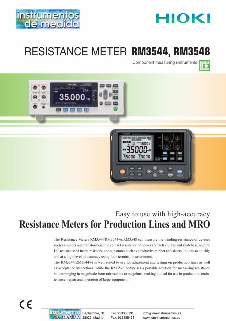
Component measuring instruments
The Resistance Meters RM3544/RM3544-01/RM3548 can measure the winding resistance of devices such as motors and transformers, the contact resistance of power contacts (relays and switches), and the DC resistance of fuses, resistors, and substrates such as conductive rubber and sheets. It does so quickly and at a high level of accuracy using four-terminal measurement.The RM3544/RM3544-01 is well suited to use for adjustment and testing on production lines as well as acceptance inspections, while the RM3548 comprises a portable solution for measuring resistance values ranging in magnitude from microohms to megohms, making it ideal for use in production, main-tenance, repair and operation of large equipment.
Resistance Meters for Production Lines and MROEasy to use with high-accuracy
RESISTANCE METER RM3544, RM3548
28022 Madrid Fax. 913885433 www.idm-instrumentos.esSeptiembre, 31 Tel. 913000191 [email protected]
2
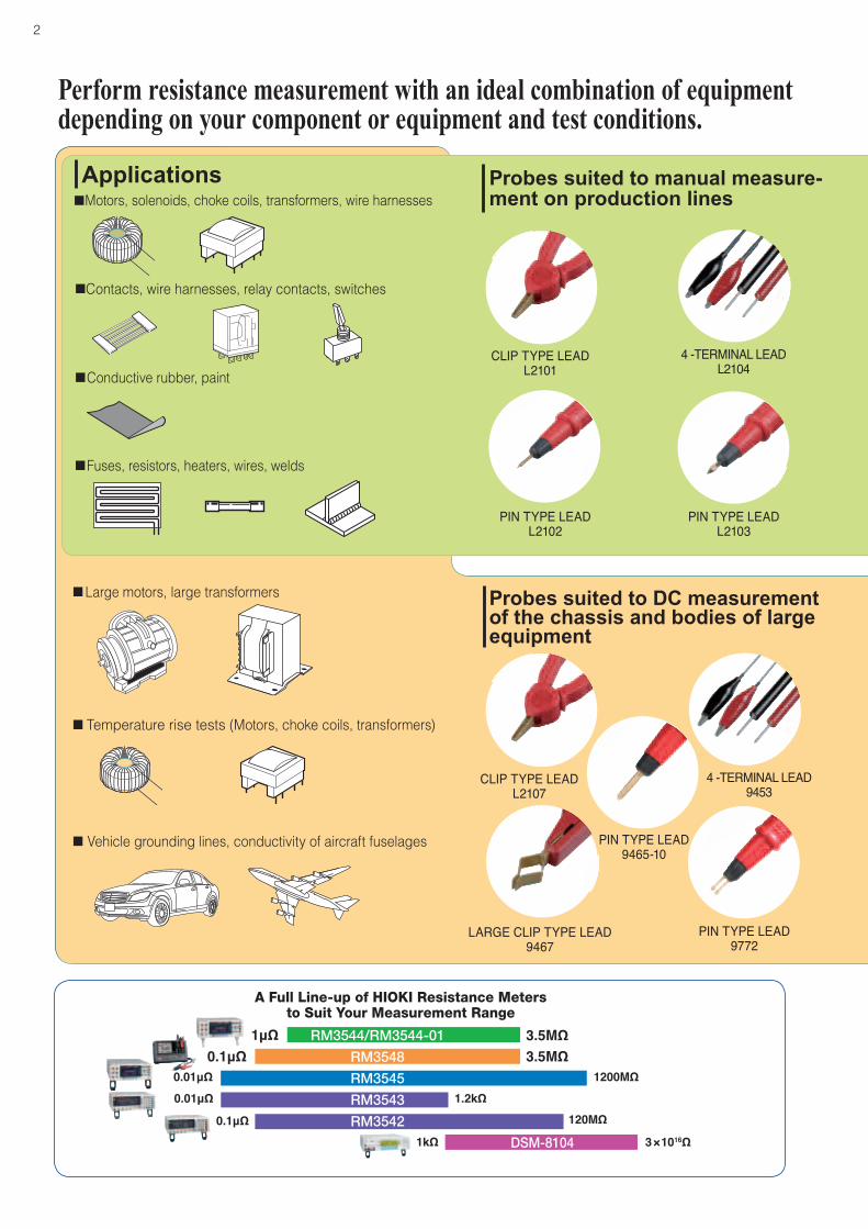
A Full Line-up of HIOKI Resistance Metersto Suit Your Measurement Range
0.01μΩ 1200MΩ
1kΩ 3×10¹⁶Ω
3.5MΩ1μΩ0.1μΩ 3.5MΩ
0.1μΩ 120MΩ0.01μΩ 1.2kΩ
RM3544/RM3544-01
RM3548
RM3545
RM3543
RM3542
DSM-8104
Perform resistance measurement with an ideal combination of equipment depending on your component or equipment and test conditions.
Probes suited to manual measure-ment on production lines
ApplicationsMotors, solenoids, choke coils, transformers, wire harnesses
Contacts, wire harnesses, relay contacts, switches
Conductive rubber, paint
Fuses, resistors, heaters, wires, welds
Large motors, large transformers
Temperature rise tests (Motors, choke coils, transformers)
Vehicle grounding lines, conductivity of aircraft fuselages
Probes suited to DC measurement of the chassis and bodies of large equipment
CLIP TYPE LEAD L2101
4 -TERMINAL LEAD L2104
PIN TYPE LEAD L2102
PIN TYPE LEAD L2103
CLIP TYPE LEAD L2107
4 -TERMINAL LEAD 9453
LARGE CLIP TYPE LEAD 9467
PIN TYPE LEAD 9772
PIN TYPE LEAD 9465-10
3
High-accuracy portable resistance metermeasures from µΩ to MΩ
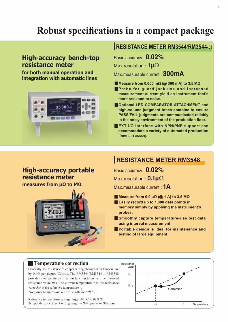
Max. measurable current : 300mAMax.resolution : 1μΩBasic accuracy : 0.02%RESISTANCE METER RM3544/RM3544-01
RESISTANCE METER RM3548
Temperature correctionGenerally, the resistance of copper wiring changes with temperature by 0.4% per degree Celsius. The RM3544/RM3544-01/RM3548 provides a temperature correction function to convert the observed resistance value Rt at the current temperature t to the resistance value Rto at the reference temperature t0.*Requires temperature sensor (Z2001 or Z2002).
Reference temperature setting range:-10 ℃ to 99.9 ℃Temperature coefficient setting range:-9,999 ppm to +9,999 ppm
High-accuracy bench-top resistance meter
Correction
Rt
Rt0
Resistancevalue
t0 t Temperature
Robust specifications in a compact package
Max. measurable current : 1AMax.resolution : 0.1μΩBasic accuracy : 0.02%
for both manual operation and integration with automatic lines
Measure from 0.0 µΩ (@ 1 A) to 3.5 MΩ Easily record up to 1,000 data points in
memory simply by applying the instrument’s probes.
Smoothly capture temperature-rise test data using interval measurement.
Portable design is ideal for maintenance and testing of large equipment.
Measure from 0.000 mΩ (@ 300 mA) to 3.5 MΩ Prob e fo r guard j ack use and inc rea sed
measurement current yield an instrument that’s more resistant to noise.
Optional LED COMPARATOR ATTACHMENT and high-volume judgment tones combine to ensure PASS/FAIL judgments are communicated reliably in the noisy environment of the production floor.
EXT I/O interface with NPN/PNP support can accommodate a variety of automated production lines (-01 model).
4
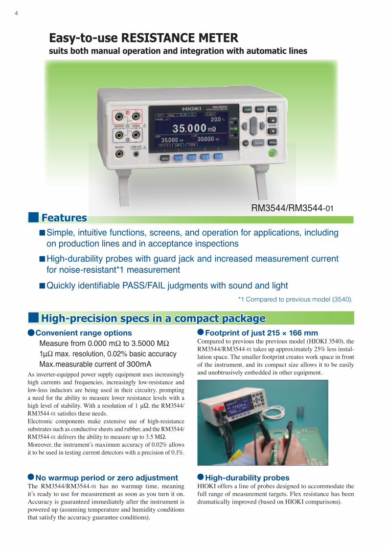
Easy-to-use RESISTANCE METERsuits both manual operation and integration with automatic lines
RM3544/RM3544-01Features Simple, intuitive functions, screens, and operation for applications, including on production lines and in acceptance inspections High-durability probes with guard jack and increased measurement current for noise-resistant*1 measurement Quickly identifiable PASS/FAIL judgments with sound and light
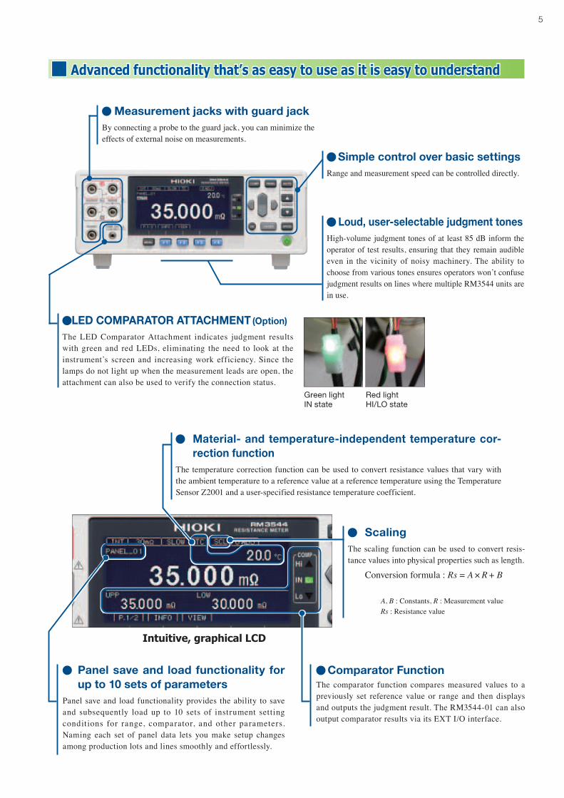
Footprintofjust215×166mmCompared to previous the previous model (HIOKI 3540), the RM3544/RM3544-01 takes up approximately 25% less instal-lation space. The smaller footprint creates work space in front of the instrument, and its compact size allows it to be easily and unobtrusively embedded in other equipment.
NowarmupperiodorzeroadjustmentThe RM3544/RM3544-01 has no warmup time, meaning it’s ready to use for measurement as soon as you turn it on. Accuracy is guaranteed immediately after the instrument is powered up (assuming temperature and humidity conditions that satisfy the accuracy guarantee conditions).
High-precision specs in a compact package
*1 Compared to previous model (3540).
Convenientrangeoptions Measure from 0.000 mΩ to 3.5000 MΩ 1μΩ max. resolution, 0.02% basic accuracy Max. measurable current of 300mAAs inverter-equipped power supply equipment uses increasingly high currents and frequencies, increasingly low-resistance and low-loss inductors are being used in their circuitry, prompting a need for the ability to measure lower resistance levels with a high level of stability. With a resolution of 1 μΩ, the RM3544/RM3544-01 satisfies these needs.Electronic components make extensive use of high-resistance substrates such as conductive sheets and rubber, and the RM3544/RM3544-01 delivers the ability to measure up to 3.5 MΩ.Moreover, the instrument’s maximum accuracy of 0.02% allows it to be used in testing current detectors with a precision of 0.1%.
High-durabilityprobesHIOKI offers a line of probes designed to accommodate the full range of measurement targets. Flex resistance has been dramatically improved (based on HIOKI comparisons).
5
Advanced functionality that’s as easy to use as it is easy to understand
MeasurementjackswithguardjackBy connecting a probe to the guard jack, you can minimize the effects of external noise on measurements.
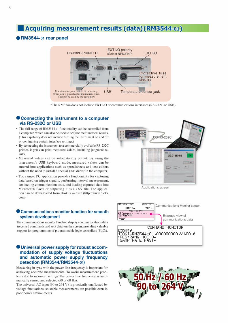
LEDCOMPARATORATTACHMENT (Option)
The LED Comparator Attachment indicates judgment results with green and red LEDs, eliminating the need to look at the instrument’s screen and increasing work efficiency. Since the lamps do not light up when the measurement leads are open, the attachment can also be used to verify the connection status.
Loud,user-selectablejudgmenttonesHigh-volume judgment tones of at least 85 dB inform the operator of test results, ensuring that they remain audible even in the vicinity of noisy machinery. The ability to choose from various tones ensures operators won’t confuse judgment results on lines where multiple RM3544 units are in use.
SimplecontroloverbasicsettingsRange and measurement speed can be controlled directly.
Red lightHI/LO state
Green lightIN state
Material-andtemperature-independent temperaturecor-rectionfunction
The temperature correction function can be used to convert resistance values that vary with the ambient temperature to a reference value at a reference temperature using the Temperature Sensor Z2001 and a user-specified resistance temperature coefficient.
Panelsaveandloadfunctionalityforupto10setsofparameters
Panel save and load functionality provides the ability to save and subsequently load up to 10 sets of instrument setting conditions for range, comparator, and other parameters. Naming each set of panel data lets you make setup changes among production lots and lines smoothly and effortlessly.
ComparatorFunctionThe comparator function compares measured values to a previously set reference value or range and then displays and outputs the judgment result. The RM3544-01 can also output comparator results via its EXT I/O interface.
Intuitive, graphical LCD
ScalingThe scaling function can be used to convert resis-tance values into physical properties such as length.
Conversion formula : Rs = A × R + B
A, B : Constants, R : Measurement valueRs : Resistance value
6
Acquiring measurement results (data)(RM3544-01)RM3544-01rearpanel
*The RM3544 does not include EXT I/O or communications interfaces (RS-232C or USB).
EXT I/OEXT I/O polarity(Select NPN/PNP)RS-232C/PRINTER
USBMaintenance jack for HIOKI use only(This jack is provided for maintenance use.
It cannot be used by the customer.)
Temperature sensor jack
Protec t ive fuse for measurement circuitry
Universalpowersupplyforrobustaccom-modation of supply voltage fluctuationsand automatic power supply frequencydetection(RM3544/RM3544-01)
Measuring in sync with the power line frequency is important for achieving accurate measurements. To avoid measurement prob-lems due to incorrect settings, the power line frequency is auto-matically sensed and selected (50 or 60 Hz).The universal AC input (90 to 264 V) is practically unaffected by voltage fluctuations, so stable measurements are possible even in poor power environments.
50 Hz / 60 Hz90 to 264 V
ConnectingtheinstrumenttoacomputerviaRS-232CorUSB
• The full range of RM3544-01 functionality can be controlled from a computer, which can also be used to acquire measurement results. (This capability does not include turning the instrument on and off or configuring certain interface settings.)
• By connecting the instrument to a commercially available RS-232C printer, it you can print measured values, including judgment re-sults.
• Measured values can be automatically output. By using the instrument’s USB keyboard mode, measured values can be entered into applications such as spreadsheets and text editors without the need to install a special USB driver in the computer.
• The sample PC application provides functionality for capturing data based on trigger signals, performing interval measurement, conducting communication tests, and loading captured data into Microsoft® Excel or outputting it as a CSV file. The applica-tion can be downloaded from Hioki’s website (http://www.hioki.com).
Applications screen
USB/RS-232C
Communicationsmonitorfunctionforsmoothsystemdevelopment
The communications monitor function displays communications data (received commands and sent data) on the screen, providing valuable support for programming of programmable logic controllers (PLCs).
Enlarged view ofcommunications data
Communications Monitor screen

7
Easy integration into automatic testing equipment (RM3544-01)
High-speed,comprehensiveproductivitysupport
• The RM3544-01 delivers the speed demanded by automatic test-ing equipment at a sophisticated level. The entire process from the start of measurement to outputting of the judgment result takes as little as 18 ms. One cycle of operation, lasting from measurement to judgment output, completes within this time.
• The RM3544-01 supports RS-232C data communications at up to 115.2 kbps.
• The instrument’s USB interface can also be used.• The EXT I/O output mode can be switched between judgment
mode and BCD mode.
FunctionalityforverifyingtheEXTI/Ocon-nectionstatusandtestingEXTI/O
In addition to allowing you to check EXT I/O signal input on the in-strument’s screen, this functionality allows you to turn output signals on or off as desired. This capability simplifies verification work dur-ing PLC programming.
Handler(EXTI/O)interfaceThe handler interface (EXT I/O) is isolated from measurement cir-cuitry, control circuitry, and the protective ground (chassis ground), providing a high level of noise resistance.
Measurement time*1
Measurement speed (ms)FAST MED SLOW
50Hz 60Hz
21 18 101 401 Tolerance: ±10% ±2 ms
*1 With TC set to ON and the comparator set to ON
t0 : Trigger pulse ON time (0.1 ms or more)t1 : Trigger pulse OFF time (1 ms or more) t2 : Measurement start time (max. 1 ms)t3 : Capture processing time ; FAST(50Hz): 20.0 ms, FAST(60Hz): 16.7 ms, MEDIUM: 100 ms, SLOW: 400 mst4 : Calculation time ; 1 ms
Example of Typical EXT I/O Timing (EOM output hold)ON
t0 t1
ON
ON
OFF
OFF
OFF OFF
OFF OFF
OFF OFFON/OFF
t3t2
t4
Measurement processing
TRIG
INDEX
EOM
HI,IN,LOERR,BCDm-n
A switch on the rear panel is used to toggle the input sig-nal polarity between NPN (sink output support) and PNP (source output support) settings depending on the PLC common polarity.
EXT I/O Input and Output Circuits EXT I/O Electrical Specifications
Inputs: Photocoupler isolation: Non-voltage contact inputs (support for current sink output)
Input ON: Residual voltage: Max. 1 V @4 mAInput OFF: Open Max. 100 μA
Outputs:Photocoupler-isolated open drain output (no-polarity)DC30Vmax, DC50mAmax/chResidual voltage: Max. 1 V @50 mA, or 0.5 V @10 mA
External power output:Output voltage: Sink output support: 5.0V±10%, Source output support: -5.0V±10%Max. output current: 100mA
Example of Typical Input SignalsTRIG : External trigger0ADJ : Zero-AdjustPRINT : PrintKEY_LOCK : Key-LockBCD_LOW : Lower digit specification when
set to BCD outputLOAD0 to LOAD3 : Panel number to loadIN0, IN1 : General-purpose input pins Output SignalsHI, IN, LO : Comparator Hi, IN, LOEOM : End of MeasurementINDEX : End of ImportERR : Measurement Fault OutputHILO : Outputs HI or LO when set to
BCD output.BCDm-n : Outputs the nth bit of the mth
digit when set to BCD output.OUT0 to OUT2 : General-purpose output pins
when set to judgment modeRNG_OUT0 toRNG_OUT3
: Outputs range information when set to BCD output.
ISO_5V : Internally Isolated 5 VISO_COM : Internally Isolated Common
When designing a control system using the EXT I/O interface, be sure to readthe instruction manual and check the necessary technical information.
EXT I/O test function screen
Output CircuitRM3544-01
ISO_COM
Internally Isolated Common
Max. 50 mA DCZener voltage = 30 V
10Ω Output
Input Circuit (Case of NPN type)RM3544-01
Input
ISO_COM
Internally Isolated Common
1kΩ
NPNEXT I/O MODE
SELECTOR
PNP
2kΩ
During processing
EXT I/O polarity(Select NPN/PNP)
8
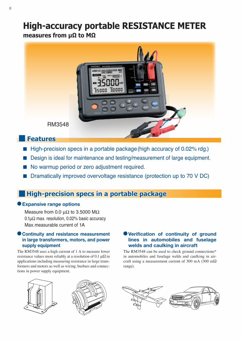
High-accuracy portable RESISTANCE METERmeasures from µΩ to MΩ
RM3548
High-precision specs in a portable package(high accuracy of 0.02% rdg.) Design is ideal for maintenance and testing/measurement of large equipment. No warmup period or zero adjustment required. Dramatically improved overvoltage resistance (protection up to 70 V DC)
High-precision specs in a portable packageExpansiverangeoptions
Measure from 0.0 μΩ to 3.5000 MΩ 0.1μΩ max. resolution, 0.02% basic accuracy Max. measurable current of 1A
Continuity and resistancemeasurementinlargetransformers,motors,andpowersupplyequipment
The RM3548 uses a high current of 1 A to measure lower resistance values more reliably at a resolution of 0.1 μΩ in applications including measuring resistance in large trans-formers and motors as well as wiring, busbars and connec-tions in power supply equipment.
Verification of continuity of groundlines in automobiles and fuselageweldsandcaulkinginaircraft
The RM3548 can be used to check ground connections* in automobiles and fuselage welds and caulking in air-craft using a measurement current of 300 mA (300 mΩ range).
Features
9
Portable, easy to use, and easy to understand
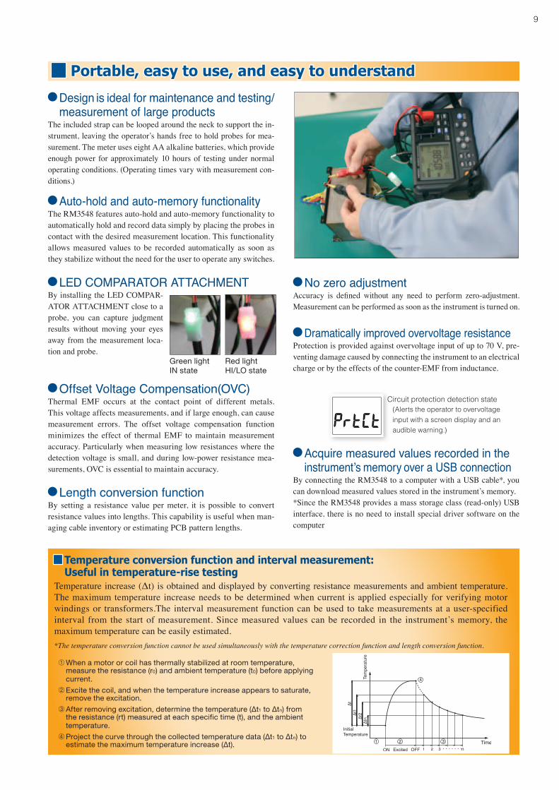
Temperature conversion function and interval measurement:Useful in temperature-rise testing
Temperature increase (Δt) is obtained and displayed by converting resistance measurements and ambient temperature.The maximum temperature increase needs to be determined when current is applied especially for verifying motor windings or transformers.The interval measurement function can be used to take measurements at a user-specified interval from the start of measurement. Since measured values can be recorded in the instrument’s memory, the maximum temperature can be easily estimated.*The temperature conversion function cannot be used simultaneously with the temperature correction function and length conversion function.
➀When a motor or coil has thermally stabilized at room temperature, measure the resistance (r0) and ambient temperature (t0) before applying current.
➁Excite the coil, and when the temperature increase appears to saturate, remove the excitation.
➂After removing excitation, determine the temperature (∆t1 to ∆tn) from the resistance (rt) measured at each specific time (t), and the ambient temperature.
➃Project the curve through the collected temperature data (∆t1 to ∆tn) to estimate the maximum temperature increase (∆t).
Design is ideal for maintenance and testing/measurement of large products
The included strap can be looped around the neck to support the in-strument, leaving the operator’s hands free to hold probes for mea-surement. The meter uses eight AA alkaline batteries, which provide enough power for approximately 10 hours of testing under normal operating conditions. (Operating times vary with measurement con-ditions.)
Auto-hold and auto-memory functionalityThe RM3548 features auto-hold and auto-memory functionality to automatically hold and record data simply by placing the probes in contact with the desired measurement location. This functionality allows measured values to be recorded automatically as soon as they stabilize without the need for the user to operate any switches.
Offset Voltage Compensation(OVC)Thermal EMF occurs at the contact point of different metals. This voltage affects measurements, and if large enough, can cause measurement errors. The offset voltage compensation function minimizes the effect of thermal EMF to maintain measurement accuracy. Particularly when measuring low resistances where the detection voltage is small, and during low-power resistance mea-surements, OVC is essential to maintain accuracy.
Length conversion functionBy setting a resistance value per meter, it is possible to convert resistance values into lengths. This capability is useful when man-aging cable inventory or estimating PCB pattern lengths.
No zero adjustmentAccuracy is defined without any need to perform zero-adjustment. Measurement can be performed as soon as the instrument is turned on.
Acquire measured values recorded in the instrument’s memory over a USB connectionBy connecting the RM3548 to a computer with a USB cable*, you can download measured values stored in the instrument’s memory. *Since the RM3548 provides a mass storage class (read-only) USB interface, there is no need to install special driver software on the computer
By installing the LED COMPAR-ATOR ATTACHMENT close to a probe, you can capture judgment results without moving your eyes away from the measurement loca-tion and probe.
Green lightIN state
Red lightHI/LO state
Dramatically improved overvoltage resistanceProtection is provided against overvoltage input of up to 70 V, pre-venting damage caused by connecting the instrument to an electrical charge or by the effects of the counter-EMF from inductance.
Circuit protection detection state(Alerts the operator to overvoltage input with a screen display and an audible warning.)
LED COMPARATOR ATTACHMENT
10
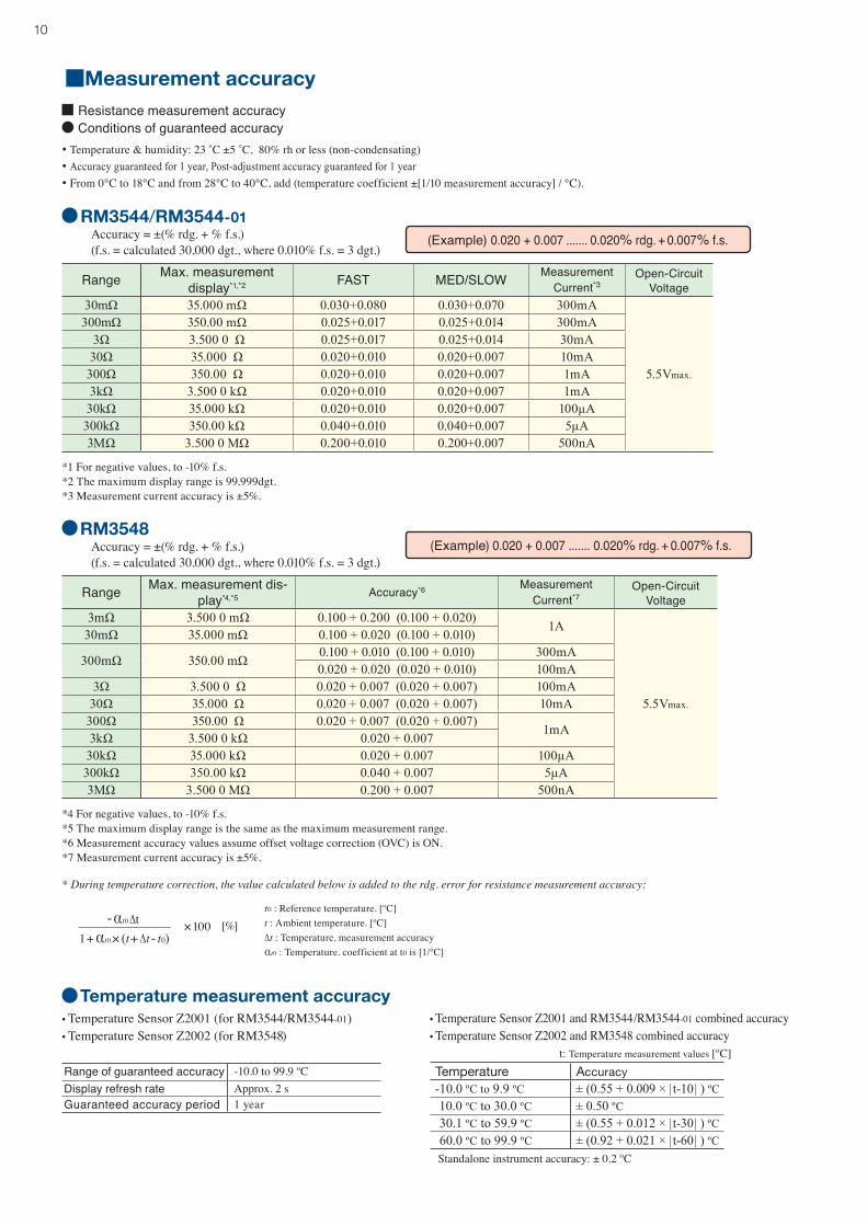
MeasurementaccuracyResistance measurement accuracy Conditions of guaranteed accuracy
• Temperature & humidity: 23 ˚C ±5 ˚C, 80% rh or less (non-condensating)• Accuracy guaranteed for 1 year, Post-adjustment accuracy guaranteed for 1 year• From 0°C to 18°C and from 28°C to 40°C, add (temperature coefficient ±[1/10 measurement accuracy] / °C).
RM3544/RM3544-01 Accuracy = ±(% rdg. + % f.s.) (f.s. = calculated 30,000 dgt., where 0.010% f.s. = 3 dgt.)
Range Max. measurement display*1,*2 FAST MED/SLOW Measurement
Current*3Open-Circuit
Voltage30mΩ 35.000 mΩ 0.030+0.080 0.030+0.070 300mA
5.5Vmax.
300mΩ 350.00 mΩ 0.025+0.017 0.025+0.014 300mA3Ω 3.500 0 Ω 0.025+0.017 0.025+0.014 30mA
30Ω 35.000 Ω 0.020+0.010 0.020+0.007 10mA300Ω 350.00 Ω 0.020+0.010 0.020+0.007 1mA3kΩ 3.500 0 kΩ 0.020+0.010 0.020+0.007 1mA
30kΩ 35.000 kΩ 0.020+0.010 0.020+0.007 100μA300kΩ 350.00 kΩ 0.040+0.010 0.040+0.007 5μA3MΩ 3.500 0 MΩ 0.200+0.010 0.200+0.007 500nA
*1 For negative values, to -10% f.s.*2 The maximum display range is 99,999dgt.*3 Measurement current accuracy is ±5%.
RM3548 Accuracy = ±(% rdg. + % f.s.) (f.s. = calculated 30,000 dgt., where 0.010% f.s. = 3 dgt.)
Range Max. measurement dis-play*4,*5 Accuracy*6 Measurement
Current*7Open-Circuit
Voltage3mΩ 3.500 0 mΩ 0.100 + 0.200 (0.100 + 0.020) 1A
5.5Vmax.
30mΩ 35.000 mΩ 0.100 + 0.020 (0.100 + 0.010)
300mΩ 350.00 mΩ 0.100 + 0.010 (0.100 + 0.010) 300mA0.020 + 0.020 (0.020 + 0.010) 100mA
3Ω 3.500 0 Ω 0.020 + 0.007 (0.020 + 0.007) 100mA30Ω 35.000 Ω 0.020 + 0.007 (0.020 + 0.007) 10mA
300Ω 350.00 Ω 0.020 + 0.007 (0.020 + 0.007) 1mA3kΩ 3.500 0 kΩ 0.020 + 0.00730kΩ 35.000 kΩ 0.020 + 0.007 100μA300kΩ 350.00 kΩ 0.040 + 0.007 5μA3MΩ 3.500 0 MΩ 0.200 + 0.007 500nA
*4 For negative values, to -10% f.s.*5 The maximum display range is the same as the maximum measurement range.*6 Measurement accuracy values assume offset voltage correction (OVC) is ON.*7 Measurement current accuracy is ±5%.
(Example) 0.020 + 0.007 ....... 0.020% rdg. + 0.007% f.s.
(Example) 0.020 + 0.007 ....... 0.020% rdg. + 0.007% f.s.
* During temperature correction, the value calculated below is added to the rdg. error for resistance measurement accuracy:
t0 : Reference temperature. [ºC]t : Ambient temperature. [ºC]Δt : Temperature. measurement accuracyαt0 : Temperature. coefficient at t0 is [1/ºC]
-αt0 Δt1+ αt0 × (t+ Δt- t0)
×100 [%]
Temperaturemeasurementaccuracy• Temperature Sensor Z2001 (for RM3544/RM3544-01)• Temperature Sensor Z2002 (for RM3548)
Range of guaranteed accuracy -10.0 to 99.9 ºCDisplay refresh rate Approx. 2 sGuaranteed accuracy period 1 year
• Temperature Sensor Z2001 and RM3544/RM3544-01 combined accuracy• Temperature Sensor Z2002 and RM3548 combined accuracy
Temperature Accuracy -10.0 ºC to 9.9 ºC ± (0.55 + 0.009 × |t-10| ) ºC 10.0 ºC to 30.0 ºC ± 0.50 ºC 30.1 ºC to 59.9 ºC ± (0.55 + 0.012 × |t-30| ) ºC 60.0 ºC to 99.9 ºC ± (0.92 + 0.021 × |t-60| ) ºC
Standalone instrument accuracy: ± 0.2 ºC
t: Temperature measurement values [ºC]
11
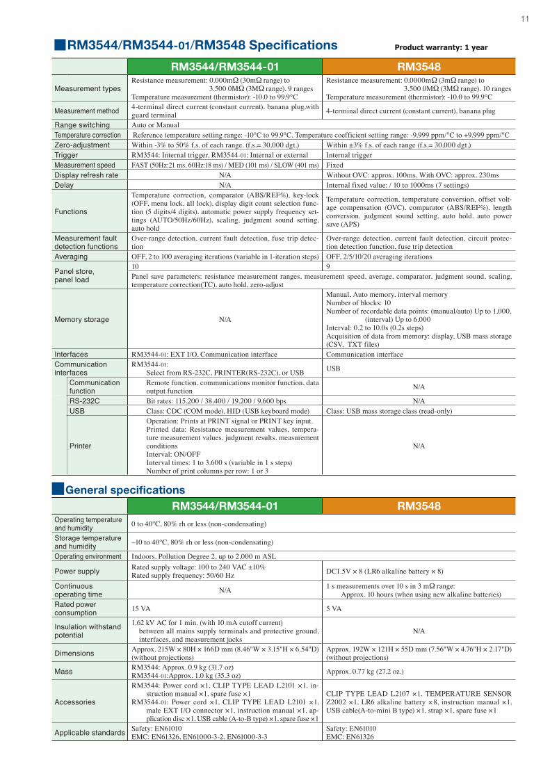
GeneralspecificationsRM3544/RM3544-01 RM3548
Operating temperature and humidity 0 to 40ºC, 80% rh or less (non-condensating)
Storage temperature and humidity –10 to 40ºC, 80% rh or less (non-condensating)
Operating environment Indoors, Pollution Degree 2, up to 2,000 m ASL
Power supply Rated supply voltage: 100 to 240 VAC ±10%Rated supply frequency: 50/60 Hz DC1.5V × 8 (LR6 alkaline battery × 8)
Continuous operating time N/A 1 s measurements over 10 s in 3 mΩ range:
Approx. 10 hours (when using new alkaline batteries)Rated power consumption 15 VA 5 VA
Insulation withstand potential
1.62 kV AC for 1 min. (with 10 mA cutoff current) between all mains supply terminals and protective ground,
interfaces, and measurement jacksN/A
Dimensions Approx. 215W × 80H × 166D mm (8.46"W × 3.15"H × 6.54"D) (without projections)
Approx. 192W × 121H × 55D mm (7.56"W × 4.76"H × 2.17"D) (without projections)
Mass RM3544: Approx. 0.9 kg (31.7 oz) RM3544-01:Approx. 1.0 kg (35.3 oz) Approx. 0.77 kg (27.2 oz.)
Accessories
RM3544: Power cord ×1, CLIP TYPE LEAD L2101 ×1, in-struction manual ×1, spare fuse ×1
RM3544-01: Power cord ×1, CLIP TYPE LEAD L2101 ×1, male EXT I/O connector ×1, instruction manual ×1, ap-plication disc ×1, USB cable (A-to-B type) ×1, spare fuse ×1
CLIP TYPE LEAD L2107 ×1, TEMPERATURE SENSOR Z2002 ×1, LR6 alkaline battery ×8, instruction manual ×1, USB cable(A-to-mini B type) ×1, strap ×1, spare fuse ×1
Applicable standards Safety: EN61010EMC: EN61326, EN61000-3-2, EN61000-3-3
Safety: EN61010EMC: EN61326
RM3544/RM3544-01 RM3548
Measurement typesResistance measurement: 0.000mΩ (30mΩ range) to 3.500 0MΩ (3MΩ range), 9 rangesTemperature measurement (thermistor): -10.0 to 99.9°C
Resistance measurement: 0.0000mΩ (3mΩ range) to 3.500 0MΩ (3MΩ range), 10 rangesTemperature measurement (thermistor): -10.0 to 99.9°C
Measurement method 4-terminal direct current (constant current), banana plug,with guard terminal 4-terminal direct current (constant current), banana plug
Range switching Auto or ManualTemperature correction Reference temperature setting range: -10°C to 99.9°C, Temperature coefficient setting range: -9,999 ppm/°C to +9,999 ppm/°C Zero-adjustment Within -3% to 50% f.s. of each range. (f.s.= 30,000 dgt.) Within ±3% f.s. of each range (f.s.= 30,000 dgt.)Trigger RM3544: Internal trigger, RM3544-01: Internal or external Internal triggerMeasurement speed FAST (50Hz:21 ms, 60Hz:18 ms) / MED (101 ms) / SLOW (401 ms) FixedDisplay refresh rate N/A Without OVC: approx. 100ms, With OVC: approx. 230msDelay N/A Internal fixed value: / 10 to 1000ms (7 settings)
Functions
Temperature correction, comparator (ABS/REF%), key-lock (OFF, menu lock, all lock), display digit count selection func-tion (5 digits/4 digits), automatic power supply frequency set-tings (AUTO/50Hz/60Hz), scaling, judgment sound setting, auto hold
Temperature correction, temperature conversion, offset volt-age compensation (OVC), comparator (ABS/REF%), length conversion, judgment sound setting, auto hold, auto power save (APS)
Measurement fault detection functions
Over-range detection, current fault detection, fuse trip detec-tion
Over-range detection, current fault detection, circuit protec-tion detection function, fuse trip detection
Averaging OFF, 2 to 100 averaging iterations (variable in 1-iteration steps) OFF, 2/5/10/20 averaging iterations
Panel store, panel load
10 9Panel save parameters: resistance measurement ranges, measurement speed, average, comparator, judgment sound, scaling, temperature correction(TC), auto hold, zero-adjust
Memory storage N/A
Manual, Auto memory, interval memoryNumber of blocks: 10Number of recordable data points: (manual/auto) Up to 1,000, (interval) Up to 6,000Interval: 0.2 to 10.0s (0.2s steps)Acquisition of data from memory: display, USB mass storage (CSV, TXT files)
Interfaces RM3544-01: EXT I/O, Communication interface Communication interfaceCommunication interfaces
RM3544-01: Select from RS-232C, PRINTER(RS-232C), or USB USB
Communication function
Remote function, communications monitor function, data output function N/A
RS-232C Bit rates: 115,200 / 38,400 / 19,200 / 9,600 bps N/AUSB Class: CDC (COM mode), HID (USB keyboard mode) Class: USB mass storage class (read-only)
Printer
Operation: Prints at PRINT signal or PRINT key input. Printed data: Resistance measurement values, tempera-
ture measurement values, judgment results, measurement conditions
Interval: ON/OFF Interval times: 1 to 3,600 s (variable in 1 s steps) Number of print columns per row: 1 or 3
N/A
RM3544/RM3544-01/RM3548Specifications Product warranty: 1 year
HEADQUARTERS 81 Koizumi, Ueda, Nagano, 386-1192, Japan TEL +81-268-28-0562 FAX +81-268-28-0568 http://www.hioki.com / E-mail: [email protected]
HIOKI USA CORPORATION TEL +1-609-409-9109 FAX +1-609-409-9108 http://www.hiokiusa.com / E-mail: [email protected] information correct as of June. 30, 2015. All specifications are subject to change without notice. RM3544E5-56E Printed in Japan
DISTRIBUTED BYHIOKI (Shanghai) SALES & TRADING CO., LTD. TEL +86-21-63910090 FAX +86-21-63910360 http://www.hioki.cn / E-mail: [email protected]
HIOKI INDIA PRIVATE LIMITED TEL +91-124-6590210 FAX +91-124-6460113 E-mail: [email protected]
HIOKI SINGAPORE PTE. LTD. TEL +65-6634-7677 FAX +65-6634-7477 E-mail: [email protected]
HIOKI KOREA CO., LTD. TEL +82-2-2183-8847 FAX +82-2-2183-3360 E-mail: [email protected]
Note: Company names and Product names appearing in this catalog are trademarks or registered trademarks of various companies.
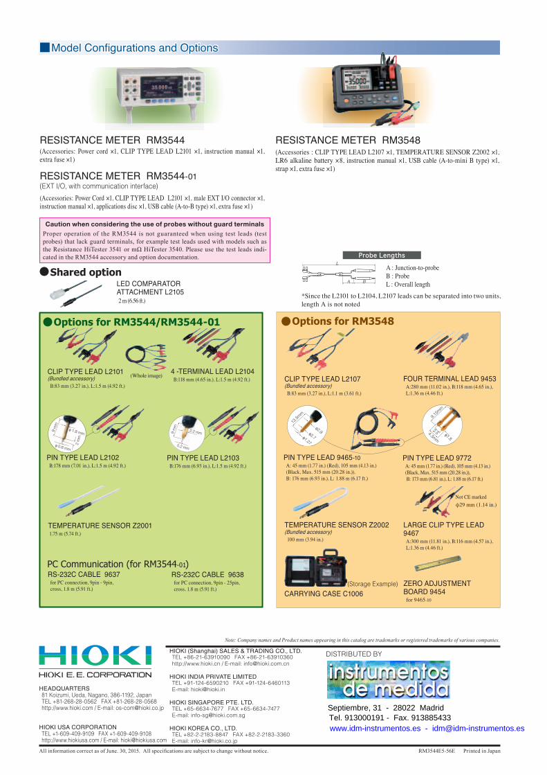
Model Configurations and Options
RESISTANCE METER RM3544(Accessories: Power cord ×1, CLIP TYPE LEAD L2101 ×1, instruction manual ×1, extra fuse ×1)
RESISTANCE METER RM3544-01(EXT I/O, with communication interface)(Accessories: Power Cord ×1, CLIP TYPE LEAD L2101 ×1, male EXT I/O connector ×1, instruction manual ×1, applications disc ×1, USB cable (A-to-B type) ×1, extra fuse ×1)
RESISTANCE METER RM3548(Accessories : CLIP TYPE LEAD L2107 ×1, TEMPERATURE SENSOR Z2002 ×1, LR6 alkaline battery ×8, instruction manual ×1, USB cable (A-to-mini B type) ×1, strap ×1, extra fuse ×1)
Probe Lengths
A : Junction-to-probeB : ProbeL : Overall length
*Since the L2101 to L2104, L2107 leads can be separated into two units, length A is not noted
LED COMPARATOR ATTACHMENT L2105 2 m (6.56 ft.)
Options for RM3544/RM3544-01
RS-232C CABLE 9637 for PC connection, 9pin - 9pin,
cross, 1.8 m (5.91 ft.)
RS-232C CABLE 9638 for PC connection, 9pin - 25pin,
cross, 1.8 m (5.91 ft.)
PC Communication (for RM3544-01)
TEMPERATURE SENSOR Z2001 1.75 m (5.74 ft.)
4 -TERMINAL LEAD L2104 B:118 mm (4.65 in.), L:1.5 m (4.92 ft.)
CLIP TYPE LEAD L2101(Bundled accessory) B:83 mm (3.27 in.), L:1.5 m (4.92 ft.)
(Whole image)
PIN TYPE LEAD L2102 B:178 mm (7.01 in.), L:1.5 m (4.92 ft.)
PIN TYPE LEAD L2103 B:176 mm (6.93 in.), L:1.5 m (4.92 ft.)
Options for RM3548
FOUR TERMINAL LEAD 9453 A:280 mm (11.02 in.), B:118 mm (4.65 in.),
L:1.36 m (4.46 ft.)
LARGE CLIP TYPE LEAD 9467 A:300 mm (11.81 in.), B:116 mm (4.57 in.),
L:1.36 m (4.46 ft.)
φ29 mm (1.14 in.)Not CE marked
PIN TYPE LEAD 9772 A: 45 mm (1.77 in.) (Red), 105 mm (4.13 in.)
(Black, Max. 515 mm (20.28 in.)), B: 173 mm (6.81 in.), L: 1.88 m (6.17 ft.)
PIN TYPE LEAD 9465-10 A: 45 mm (1.77 in.) (Red), 105 mm (4.13 in.)
(Black, Max. 515 mm (20.28 in.)), B: 176 mm (6.93 in.), L: 1.88 m (6.17 ft.)
CLIP TYPE LEAD L2107(Bundled accessory) B:83 mm (3.27 in.), L:1.1 m (3.61 ft.)
ZERO ADJUSTMENT BOARD 9454 for 9465-10
TEMPERATURE SENSOR Z2002(Bundled accessory) 100 mm (3.94 in.)
CARRYING CASE C1006(Storage Example)
Shared option
CautionwhenconsideringtheuseofprobeswithoutguardterminalsProper operation of the RM3544 is not guaranteed when using test leads (test probes) that lack guard terminals, for example test leads used with models such as the Resistance HiTester 3541 or mΩ HiTester 3540. Please use the test leads indi-cated in the RM3544 accessory and option documentation.
Septiembre, 31 - 28022 MadridTel. 913000191 - Fax. 913885433www.idm-instrumentos.es - [email protected]