Embed Size (px)
Citation preview
Resistance and Ohm’s LawObject: The purpose of this lab is to begin experimenting with the variables that contribute to the operation of an electrical circuit. There are two parts to this lab.
Reference: RHW Ch. 26
Apparatus: 1. AC/DC Electronics Lab Board2. Various resistors3. Extech basic multimeter4. Heavy-duty galvanometer5. Wire leads
Introduction:You have learned that a potential difference provides the incentive for charge to flow from one
point to another point. Positive charges will move towards lower potentials, whereas negative charges do the opposite and will move towards a higher potential (as long as you also provide the means for which the charge can move, with some sort of conductor, for example.) So, if we connect the terminals of a battery, a source of potential difference, with a conducting wire, we would expect to measure charges moving around the circuit. We will, for the time being, assume that there are positive charges moving from the higher potential terminal of the battery to the lower potential terminal (+ to -).1 Now, if we were to place a microscopic photo-gate along the wire we could measure the charges passing by any point along the wire as a function of time. The rate at which charge passes some point is defined as the current:
I = dqdt
So now we have two variables: the voltage (which provides the incentive for charge to move), and the current (the actual movement of charges). It should be apparent that these two variables are related to one another! For many materials, at least over a small range of applied voltages, the ratio of these two variables is a constant. The German physicist George Simon Ohm was one of the first to really notice this relationship and to formally build a theory of electrical behavior which included this relationship, thus we refer to this relationship as Ohm’s Law:
R =VI⇒V = IR
The value, R, is referred to as the resistance of the conductor. It depends on the type of material (resistivity, ρ), the cross-sectional area through which the charge is trying to pass (area, A), and the distance over which the charge needs to move to complete a circuit (length, L):
Resistance and Ohm’s Law
WCUPA Physics 1
1 Note that in most cases it is actually negative charges moving from the lower potential to the higher potential, but the effect is, for our purposes here, the same. For example, a positive moving right is equivalent to a negative moving left.
R =ρLA
The resistance is measured in volts per ampere, or Ohm (Ω=V/A). Typical carbon resistors such as the ones used in todays lab are color coded to indicate the value of the resistance and the tolerance, or uncertainty in the stated value. A chart is provided at the end of the lab under the “references” heading.
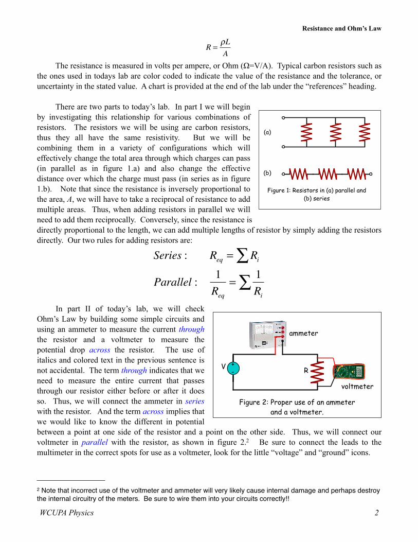
There are two parts to today’s lab. In part I we will begin by investigating this relationship for various combinations of resistors. The resistors we will be using are carbon resistors, thus they all have the same resistivity. But we will be combining them in a variety of configurations which will effectively change the total area through which charges can pass (in parallel as in figure 1.a) and also change the effective distance over which the charge must pass (in series as in figure 1.b). Note that since the resistance is inversely proportional to the area, A, we will have to take a reciprocal of resistance to add multiple areas. Thus, when adding resistors in parallel we will need to add them reciprocally. Conversely, since the resistance is directly proportional to the length, we can add multiple lengths of resistor by simply adding the resistors directly. Our two rules for adding resistors are:
Series : Req = Ri∑Parallel : 1
Req=
1Ri
∑In part II of today’s lab, we will check
Ohm’s Law by building some simple circuits and using an ammeter to measure the current through the resistor and a voltmeter to measure the potential drop across the resistor. The use of italics and colored text in the previous sentence is not accidental. The term through indicates that we need to measure the entire current that passes through our resistor either before or after it does so. Thus, we will connect the ammeter in series with the resistor. And the term across implies that we would like to know the different in potential between a point at one side of the resistor and a point on the other side. Thus, we will connect our voltmeter in parallel with the resistor, as shown in figure 2.2 Be sure to connect the leads to the multimeter in the correct spots for use as a voltmeter, look for the little “voltage” and “ground” icons.
(a)
(b)
Figure 1: Resistors in (a) parallel and
(b) series
Figure 2: Proper use of an ammeter
and a voltmeter.
R+
- V
ammeter
voltmeter
Resistance and Ohm’s Law
WCUPA Physics 2
2 Note that incorrect use of the voltmeter and ammeter will very likely cause internal damage and perhaps destroy the internal circuitry of the meters. Be sure to wire them into your circuits correctly!!
Procedure, Part I:
1. Choose three resistors of the same value. Enter their sets of colors in Table 1 below. We will refer to the first as #1, the next as #2 and the third as #3.
2. Determine the coded value of your resistors. Enter the value in the column labeled “Coded Resistance” in Table 1. Enter the Tolerance value as indicated by the color of the fourth band under “Tolerance.”
3. Use the Multimeter to measure the resistance of each of your three resistors.3 Enter these values in Table 1.
4. Is the measured resistance within the allowed tolerance? Indicate this in the table.
Color
1st 2nd 3rdCoded
ResistanceMeasured Resistance Tolerance Within
Stated?
#1
#2
#3
Table 1
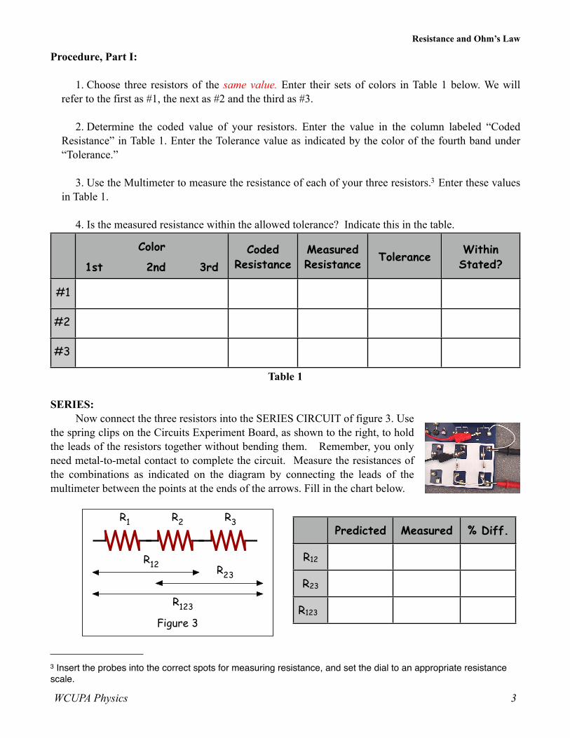
SERIES:Now connect the three resistors into the SERIES CIRCUIT of figure 3. Use
the spring clips on the Circuits Experiment Board, as shown to the right, to hold the leads of the resistors together without bending them. Remember, you only need metal-to-metal contact to complete the circuit. Measure the resistances of the combinations as indicated on the diagram by connecting the leads of the multimeter between the points at the ends of the arrows. Fill in the chart below.
Figure 3
R1 R2 R3
R12R23
R123
Resistance and Ohm’s Law
WCUPA Physics 3
3 Insert the probes into the correct spots for measuring resistance, and set the dial to an appropriate resistance scale.
Predicted Measured % Diff.
R12
R23
R123
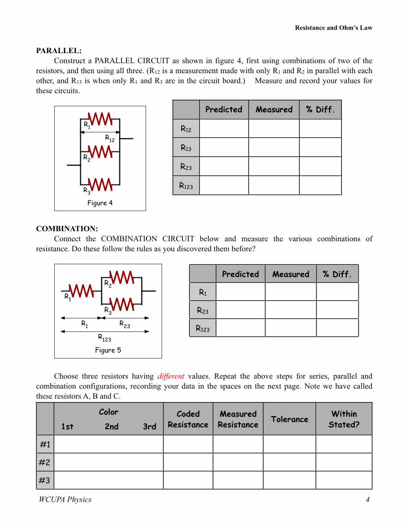
PARALLEL:Construct a PARALLEL CIRCUIT as shown in figure 4, first using combinations of two of the
resistors, and then using all three. (R12 is a measurement made with only R1 and R2 in parallel with each other, and R13 is when only R1 and R3 are in the circuit board.) Measure and record your values for these circuits.
R1
R2
R3
R12
Figure 4
COMBINATION:Connect the COMBINATION CIRCUIT below and measure the various combinations of
resistance. Do these follow the rules as you discovered them before?
R23
R1
R2
R3
Figure 5
R1
R123
Choose three resistors having different values. Repeat the above steps for series, parallel and combination configurations, recording your data in the spaces on the next page. Note we have called these resistors A, B and C.
Color
1st 2nd 3rdCoded
ResistanceMeasured Resistance Tolerance Within
Stated?
#1
#2
#3
Resistance and Ohm’s Law
WCUPA Physics 4
Predicted Measured % Diff.
R12
R13
R23
R123
Predicted Measured % Diff.
R1
R23
R123
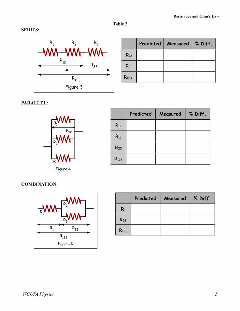
Table 2SERIES:
Figure 3
R1 R2 R3
R12R23
R123
PARALLEL:
R1
R2
R3
R12
Figure 4
COMBINATION:
R23
R1
R2
R3
Figure 5
R1
R123
Resistance and Ohm’s Law
WCUPA Physics 5
Predicted Measured % Diff.
R12
R23
R123
Predicted Measured % Diff.
R12
R13
R23
R123
Predicted Measured % Diff.
R1
R23
R123

Discussion, Part I:
(1) How does the % error compare to the coded tolerance for your resistors?
(2) What is the apparent rule for combining equal resistances in series circuits? In parallel circuits? Cite evidence from your data to support your conclusions.
(3) What is the apparent rule for combining unequal resistances in series circuits? In parallel circuits? Cite evidence from your data to support your conclusions
(4) What is the apparent rule for the total resistance when resistors are added up in series? In parallel? Cite evidence from your data to support your conclusions.
Procedure, Part II:
1. Select about 4-5 resistors ranging from about 25 Ω to 1000 Ω. Use the multimeter to measure each of the carbon resistors selected. i.e.--Place a resistor on a piece of paper and touch the probes of the multimeter to the wire ends of the resistor. Ensure that the red and black probes make electrical contact on the two wires leads of the resistors. The multimeter will display the resistance in ohms. Repeat for each of your resistors. Record the values of the resistances in order of smallest to largest in a replica of the chart below in your lab notebook, and in an Excel spreadsheet.
Resistance, Ω Current, A Voltage, V V/R
#1
#2
#3
#4
#5
Table 3
2. Now take the first (lowest valued) resistor and construct the circuit of figure 2. Use the white wires to make any connections you may need to complete the circuit, as shown to the right.
3. Measure the voltage, in volts, and current, in amperes, and record your values in your chart in your notebook and in Excel.
4. Repeat for all of your resistors. (Note any changes you make in your procedure along the way. For example, if you switch sensitivity scales on the voltmeter or ammeter, this should be noted!)
Resistance and Ohm’s Law
WCUPA Physics 6
Data Processing & Discussion:
5. Using Excel, construct a graph of current vs. resistance (I vs. R). What is the shape of this graph? What kind of mathematical relationship does it suggest between current and resistance?
6. Plot another graph of current vs. the reciprocal of the resistance (I vs. I/R). What is the shape of this graph? What kind of mathematical relationship does it suggest between current and resistance? Find the slope of the graph. Compare the slope to the voltage across the resistors.
7. Ohm's Law states that the product of the Current and Resistance gives the Voltage. Does your data concur with this?
To Turn in Next Week:1) Abstract2) Charts and accompanying diagrams (the can be hand sketched)3) Answers to questions under “Discussion” sections above.
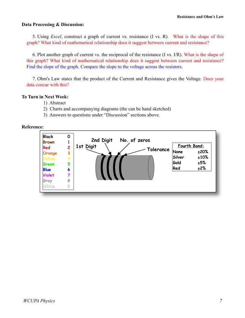
Reference:
1st Digit 2nd Digit No. of zeros
Tolerance
Black 0Brown 1Red 2Orange 3Yellow 4Green 5Blue 6Violet 7Gray 8White 9
Fourth Band:None ±20%Silver ±10%Gold ±5%Red ±2%
Resistance and Ohm’s Law
WCUPA Physics 7


