Embed Size (px)
Citation preview

Resilient Multicast Support for Continuous-Media Applications
X. Xu, A. Myers, H. Zhang and R. Yavatkar
CMU and Intel Corp
NOSSDAV, 1997

Introduction
• IP multicast presents opportunity for large-scale continuous media– Tools: nv, vat, vic ivs
• ‘Real-time’ assumed that no retransmission– Retransmissions add delay
– Instead, concentrate on FEC, client-side, etc.
• But low-delay only needed for interactivity– Example: MBONE broadcast of class
• Even if some need interactivity, not all– Example: only those asking question
• Most can allow some retransmissions

Approach
• Many Reliable Multicasts uses retransmission– PGM– LMS– SRM– …
• But do full repair
• Multimedia can tolerate some loss
• In fact, tradeoff in loss and latency
• Do semi-repair based on latency and loss tolerance– Resilient multicast

Outline
• Introduction
Characteristics of Resilient Multicast
• Reliable Multicast (SRM)
• Structure Oriented Resilient Multicast
• Evaluation
• Conclusions
Characteristics of Resilient Multicast
• Reliable vs. Resilient– Shared white-board (wb) vs. continuous media
(cm)
• In wb, every packet must arrive eventually– Cm can tolerate some loss and timing matters
• In wb, bursty traffic, lower data rate– Cm steady but high, so can cause congestion and
needs localized recovery
• In wb, every app has every packet (to undo)– Cm has only finite buffer so everyone cannot
repair
Reliable Multicast Protocols
• TCP has ack for every packet received
• In multicast, this would be too many acks for server– Called ACK Implosion
• Instead, mcast uses:– Negative acknowledgements (NACKS)
– NACK aggregation (to avoid implosion)
– Selective retransmission
• SRM is good example (used in wb)– Floyd, Jacobsen, McCanne, SIGCOMM 1995

Scalable Reliable Multicast (SRM)
• Upon loss, receiver multicast NACK to all
• Upon receiving NACK, any member can repair
• Do avoid duplicate NACKs and retransmissions, set random timer
• Timers tough– Too low, duplicates, Too high, large latency
• But with large group, even little loss means all must process– 1000 receivers, 1 loses packet at any time, all
must see NACK and retransmission– Crying Baby

SRM Improvements
• Send NACKS to only local group– Use smaller TTL field to limit scope
• How effective?– Use mping with different TTL values
– 224.2.127.254 (typical)
– Try from CMU and from Berkeley

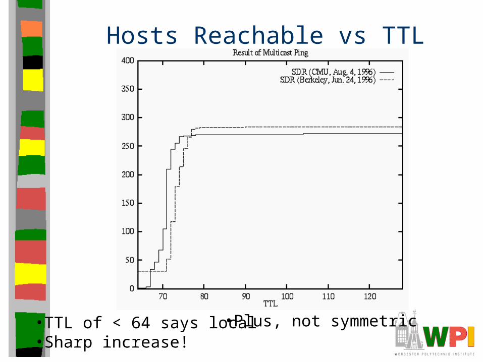
Hosts Reachable vs TTL
•TTL of < 64 says local•Sharp increase!
•Plus, not symmetric
Outline
• Introduction
• Characteristics of Resilient Multicast
• Reliable Multicast (SRM)
Structure Oriented Resilient Multicast
• Evaluation
• Conclusions

Structure Oriented Resilient Multicast (STORM) Goals
• Minimize overhead of control since CM is high bwidth
• Minimize delay in recovery since too late is no good
• Local recovery to reduce implosion and crying baby effects
STORM Overview
• NACKs and repair along structure laid on endpoints– Endpoints are leaves and “routers”
• State for this extra tree is light– List of parent nodes (multi-parent tree)
– Level in tree of self
– Delay histogram of packets received
– Timers for NACK packets sent to parent
– List of NACKs from children not fixed
– Only last two are shared, so easy to maintain
• Recovery– NACK from child then unicast repair
– If does not have packet, wait for it then send

Building the Recovery Structure• receiver first joins, does expanding ring search (ERS)
– Mcast out increasing TTL values
– Those in tree unicast back perceived loss rate as a function of playback delay
• When have enough select parents
Del
ay (
ms)
Loss (percent)
Selection of Parent Nodes
• Perceived loss as a function of buffer size– As buffer increases, perceived loss decreases
since can get repair
• In selecting parent, use to decide if ok
• Example:– C needs parent and has 200 ms buffer
– A 90% packets within 10ms, 92% within 100ms
– B 80% within 150ms, 95% within 150ms
– Would choose B
• To above example, need to add RTT to parent to see if suitable
Loop Avoidance
• May have loop in parent structure– Will prevent repair if all lost
• Use level numbers to prevent
• Can only choose parent with lower number
• Level assigned via:– Hop count to root
– Measured RTT to root
• If all have same level, a problem– Assign ‘minor number’ randomly

Adapting the Structure
• Performance of network may degrade
• Parents may come and go
• Keep ratio of NACKs to parent and repairs from parent– If drops too low, remove parent
• If need more parents, ERS again
• Rank parents: 1, 2, …– Better ones get more proportional NACKs

Outline
• Introduction
• Characteristics of Resilient Multicast
• Reliable Multicast (SRM)
• Structure Oriented Resilient Multicast
Evaluation
• Conclusions

Evaluation
• Implement STORM and SRM in vat
• Conduct experiments on MBONE
• Implement STORM and SRM in simulator
• Evaluate scalability
Performance Metrics
• Performance improvement to application– Initial loss rate
– Final loss rate
• Overhead incurred by protocol– Bandwidth consumed
Unicast is unit 1, assume multicast to N is N/2
– Processing time
• Cost is avg repair packets sent for each recovered packet

Experiments over the MBONE
8-12 sites, typical topology above with mr
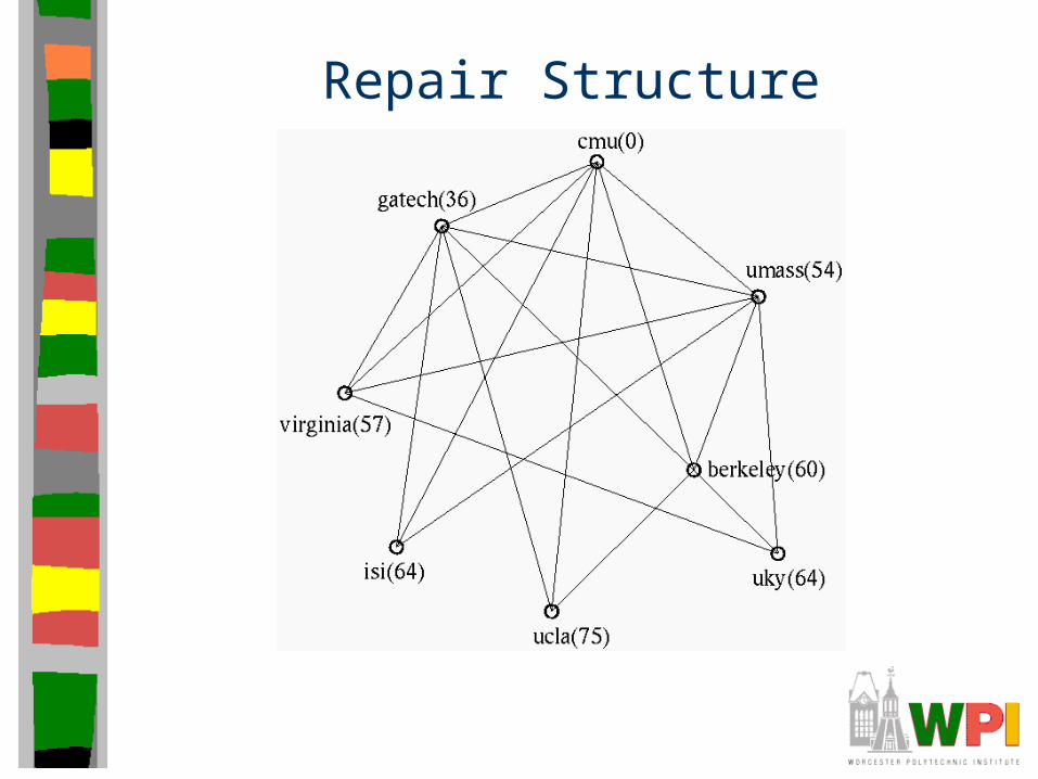
Repair Structure

Parameters
• Mcast repair– Run STORM vat– Run SRM vat 10 minutes later
• Constants– 5 minutes
– PCM encoded audio (172 byte/pack, 50 pack/sec)
– 3 had 200 ms buffers, rest had 500ms buffers
• Many experiments, show results from 6– All had same topology
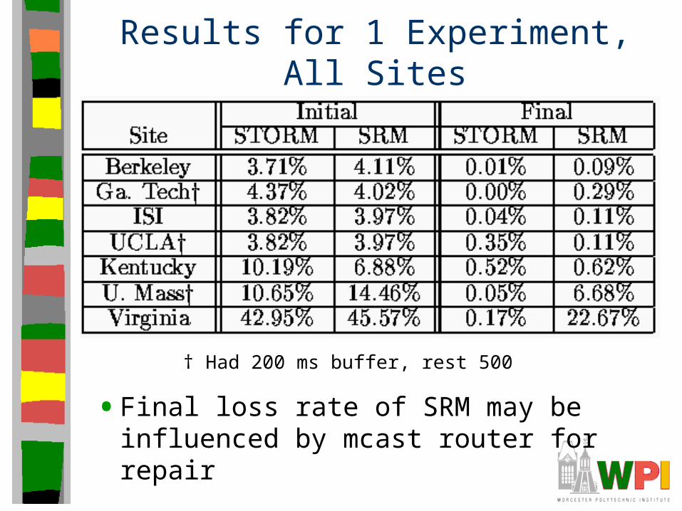
Results for 1 Experiment, All Sites
• Final loss rate of SRM may be influenced by mcast router for repair
† Had 200 ms buffer, rest 500
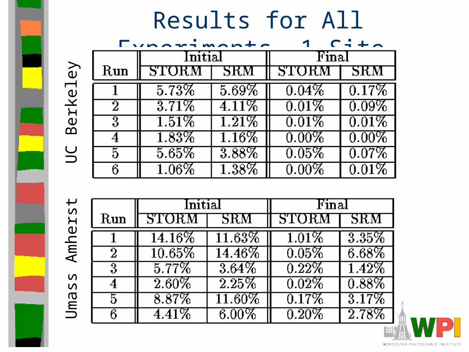
Results for All Experiments, 1 Site
UC
Ber
kele
yU
mas
s A
mhe
rst

Cost of Repair
Benefits of localized recoverySimulation suggests is real, not from different network condition

Cost of Repair
STORM send and receive about equalSRM sends fewer packets, normalized is more

STORM Dynamic Session(Number of Receivers)
• Receivers come and go (How often?)
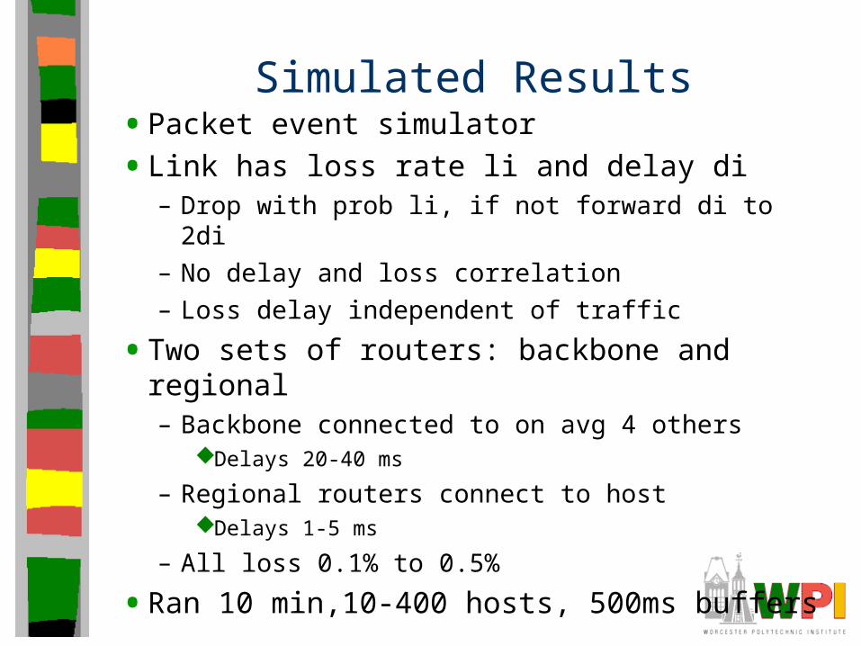
Simulated Results• Packet event simulator
• Link has loss rate li and delay di– Drop with prob li, if not forward di to 2di
– No delay and loss correlation
– Loss delay independent of traffic
• Two sets of routers: backbone and regional– Backbone connected to on avg 4 others
Delays 20-40 ms
– Regional routers connect to hostDelays 1-5 ms
– All loss 0.1% to 0.5%
• Ran 10 min,10-400 hosts, 500ms buffers

Simulated Resultsof Overhead
Overhead increases only by small constantwith group size
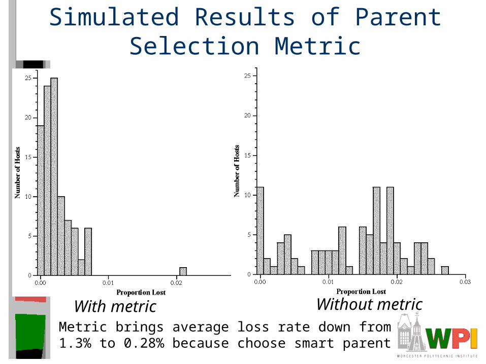
Simulated Results of Parent Selection Metric
With metric Without metricMetric brings average loss rate down from1.3% to 0.28% because choose smart parent
Conclusion
• Receiver determines own quality tradeoff between loss and latency– Allows both interactive and passive receivers
– Use to select repair node based on quality
• Repair done locally by separate tree
• Evaluation on MBONE and simulation
• Efficient (scales well) and Effective (repairs well)

Evaluation of Science?
• Category of Paper
• Science Evaluation (1-10)?
• Space devoted to Experiments?