Embed Size (px)
Citation preview
Resilient Digital Image Watermarking forDocument Authentication
Jonathan Blackledge and Oleksandr Iakovenko
Abstract—We consider the applications of the Discrete Co-sine Transform (DCT) and then a Chirp coding method forproducing a highly robust system for watermarking imagesusing a block partitioning approach subject to a self-alignmentstrategy and bit error correction. The applications for thealgorithms presented and the system developed include thecopyright protection of images and Digital Right Managementfor image libraries, for example. However, the principal focusof the research reported in this paper is on the use of print-scan and e-display-scan image authentication for use in e-ticketswhere QR code, for example, are embedded in a full colourimage of the ticket holder. This requires that an embeddingprocedure is developed that is highly robust to blur, noise,geometric distortions such as rotation, shift and barrel and thepartial removal of image segments, all of which are consideredin regard to the resilience of the method proposed and itspractical realisation in a real operating environment.
Index Terms—Resilient Watermarking, DCT, Chirp Coding,Block Embedding, Binary Information Hiding
I. INTRODUCTION
THE watermarking of digital images has become acommon concern with regard to copyright protection
and Digital Rights Management. The principal aim is todesign algorithms which provide for the authentication ofsingle and/or multiple image frames by hiding informationin an image that is encrypted or otherwise [1]. A largeamount of copyright information now resides in the formof digital images especially with regard to the growth ofelectronic publishing. Moreover, the future of networkedmultimedia systems is becoming increasingly conditionedby the development of efficient methods to protect owner-ship rights against unauthorised copying and redistribution.Digital image watermarking has emerged as a candidateto solve this problem and since the mid-1990s there hasbeen a convergence of a number of different informationprotection technologies whose theme is hiding (as opposed toencrypting) digital information. In this context, we present abrief introduction on watermarking and Steganography whichis given in the following section.
A. Watermarking and Steganography
Information hiding can refer to either making additionalinformation imperceptible or keeping the existence of the
Manuscript received on 1 August, 2013; and revised 20 November, 2013.This work was supported by the Science Foundation Ireland and by theErasmus Mundus EWENT Programme, Warsaw University of Technology,Poland.
Jonathan Blackledge is the SFI Stokes Professor, School of Electri-cal and Electronic Engineering, Dublin Institute of Technology, Ireland.Email:[email protected]
Oleksandr Iakovenko is Assistant Professor, Department of Com-puter Science, Odessa National Polytechnic University, Odessa, Ukraine.Email:[email protected]
information secret. Important sub-disciplines of informa-tion hiding are Steganography and watermarking which areconcerned with techniques that are used to imperceptiblyconvey information. However, they are two different anddistinct disciplines. Watermarking is the practice of hidingan information source (copyright information, for example)in a signal or image without degrading its quality in sucha way that it is expected to be permanently embedded intothe data and can be detected at a later time. Steganographyis the study of the techniques used to hide one messageinside another, without disclosing the existence of the hiddenmessage or making it apparent to an observer that it exists.Digital image watermarking and Steganography are thusdistinguished from each other as follows (e.g. [2], [3] and[4]):
1) Steganography is the ‘art’ of writing hidden messagesin such a way that no one, apart from the senderand intended recipient, suspects the existence of themessage whereas the information hidden by a digitalwatermarking system (which can also refer to theapplication of visible watermarks, commonly used toprotect image samples, for example, from unauthoriseduse) is always associated with the object to be protectedor its owner (Steganographic systems focusing on justhiding information).
2) The purpose of Steganography is to provide for thecovert communication between two parties whose ex-istence is unknown to a possible attacker, a successfulattack being the detection of the existence of this covertcommunication.
3) Watermarking has an additional requirement with re-gard to its robustness against possible attacks so thateven if the existence of the hidden information isknown, it should be hard for an attacker to destroythe watermark (Steganography being mainly concernedwith the non-detection of hidden data while watermark-ing is concerned with potential removal by an attack).
4) Steganographic communications are usually point-to-point (between sender and receiver) while watermark-ing techniques are usually one-to-many and whileSteganography is primarily concerned with the capac-ity of hidden information and its impact on perception,watermarking can focus on the robustness of relativelysmall amounts of hidden data compared to the size andresolution of the host.
B. Principal Components of Digital Watermarking
All watermarking schemes share the same generic build-ing blocks, namely, watermark embedding and informationextraction [5].

1) Watermark Embedding (Signature Casting): The em-bedded data is the watermark that one wishes to embed. It isusually hidden in data referred to as a ‘cover’ to produce the‘watermarked cover’. The inputs to the embedding systemare the watermark, the cover and an optional key (whichmay include system parameters). The key is used to controlthe embedding process so as to restrict detection and/orrecovery of the embedded data to parties who know of it.The watermarked cover may face some intentional and/orunintentional distortion that may affect the existence of thewatermark.
2) Watermark Detection System (Extraction): The inputsto the detection system are the possibly distorted water-marked cover, the key and depending on the method, theoriginal cover or the original watermark. Its output is eitherthe recovered watermark or some kind of confidence measureindicating how likely it is for a given watermark at the inputto be present in the data under inspection. Many currentwatermarking schemes may be viewed as spread-spectrumcommunication systems whose aim is to send the watermarkbetween two parties with two sources of noise:
• noise due to the original cover;• noise due to processing.
C. Fragility and Robustness of Watermarked Images
One of the most important issues in modern image wa-termarking development concerns the issue of robustness.In general, image watermarking methods fall into two basiccategories:
• fragile watermarks;• robust watermarks.Fragile watermarks can be destroyed as soon as the image
is modified in some way. They are usually applied to detectmodifications of the watermarked data rather than con-veying unreadable information. Compared to cryptographictechniques in regard to data authentication, there are twosignificant benefits that arise from using a watermark:
• the signature becomes embedded in the message;• it is possible to create ‘soft authentication’ algorithms
that offer a multi-valued measure that accounts fordifferent unintentional transformations that the data mayhave suffered instead of a binary True/False answergiven by cryptography-based authentication.
Robust watermarks have the property that it is not feasibleto remove them or make them useless without destroyingthe image at the same time. This usually means that themark should be embedded in the most robustly significantcomponents of the object. It also means that the hiddeninformation, or at least a significant portion of it, can berecovered subject to distortion from geometric features, noiseand blur etc. that occur when the image is printed andscanned, for example, or when it is transmitted in a noisyenvironment and/or compressed for archiving.
With regard to the generic robustness of a watermarkedimage, the principal goal is to prevent attacks designed todiminish or remove the presence of a watermark from itsassociated content while preserving the content so that it isnot made redundant after an attack has taken place. Importantexamples of ‘robustness to attacks’ are as follows:
1) Additive Noise: This may happen (unintentionally)in certain applications such as D/A (printing) and A/D(scanning) converters or from transmission errors. It can alsohappen intentionally by an attacker who is trying to destroythe watermark (or make it undetectable) by adding noise tothe watermarked cover.
2) Filtering: Linear filtering such as low-pass filtering(e.g. a Gaussian Blur) or non-linear filtering such as medianfiltering.
3) Collusion Attack: In some watermarking schemes, ifan image has been watermarked many times using differentkeys, it is possible to collect many such copies and ‘average’them into a composite image that closely resembles theoriginal image and does not contain any useful watermarkingdata [6].
4) Inversion Attack (Elimination Attack): An attackermay try to estimate the watermark and then remove it bysubtracting the estimate or reverse the insertion process toremove the watermark. This means that an attacked imagecan not be considered to contain a watermark at all (evenusing a more sophisticated detector). Note, that with differentwatermarked objects, it is possible to improve the estimateof the watermark by simple averaging.
5) Lossy Compression: This is generally an uninten-tional attack which often appears in multimedia applications.Nearly all digital images that are currently distributed via theInternet are in compressed form. Lossy image compressionalgorithms are designed to disregard redundant perceptually-insignificant information in the coding process. Watermark-ing tries to add invisible information to the image in sucha way that it is not perceptually significant. An optimalimage coder will therefore simply remove any embeddedwatermark information. However, even state-of-the-art imagecoding such as JPEG 2000++ does not achieve optimalcoding performance and therefore there is a ‘distortion gap’that can be exploited for watermarking.
D. About this Paper
A commonly used image watermarking method is basedon the replacement of the Least Significant Bits (LSB) in datasamples of host images with bits of hidden data. However,this approach is not applicable with common multimediafile formats as modern compression techniques can severelydistort the LSB during the compression process. Commonexamples are JPEG and MPEG formats which store multi-media information in the form of rounded (nearest integer)spectral components using the (Discrete) Cosine Transform.Quantisation in the spectral domain distorts data in thespatial domain. This leads to the near complete eliminationof the LSB embedded data during compression operations.However, while LSB embedding can not be applied in thespatial domain, it can still be applied in spectral domain.Thus, the Discrete Cosine Transform (DCT) coefficients of aJPEG image can be the subject of LSB based watermarking.
In this paper we address a method that uses a spectralembedding pattern approach on a block-by-block basis. Thefocus of the method is on the generation of very highresilience full colour image watermarking that can be used ona print-scan basis or an e-display-scan basis for applicationsthat include e-tickets in which QR codes are embedded

in an image of the ticket holders portrait, for example.After providing a brief overview of watermarking techniquesgiven in Section II, we consider a new block based DCTapproach and present details of its performance to variousattacks associated with low resolution scans of an imagewatermarked using the algorithms developed. This is thesubject of Section III (the DCT based algorithm) and SectionIV (evaluation of the algorithm) in which the limitationsassociated with the DCT-based algorithm are also studied.
The limitations of the DCT lead to the study of anotherblock based method in which the DCT is replaced with afrequency modulated wavelet or ‘Chirp coding’ techniquewhich improves the robustness of the algorithms further(particularly with regard to additive noise) by virtue of thefact that the data is embedded using a phase only spectrum.This is the subject of Section V.
In order to exploit either approach (i.e. the DCT or Chirpcoding method) for the development of a practically viablee-display/e-scan authentication system, it is necessary to con-sider algorithms for the automatic alignment of the scannedimage including compensating for (partial) rotation, scaleand shift, perspective and wide-angle distortion. All of theseeffects can occur when a digital image is acquired througha hand-held digital camera and can lead to significant errorsbeing generated in the watermark extraction process. In thispaper, new algorithms are proposed to solve these problemsas given in Section VI with an experimental evaluation beingprovided in Section VII.
The originality of the work reported in this paper relatesprimarily to the algorithms associated with DCT and Chirp-coding based embedding techniques used, to the extractionprocesses applied, and, to the new self-alignment algorithmsbased on the watermark itself. The approach taken providesa set of procedures that can yield a fully automated systemfor high resilience watermarking with a range of practicalapplications.
II. OVERVIEW OF IMAGE WATERMARKING TECHNIQUES
Image watermarking algorithms fall into two fundamentalcategories:
• spatial techniques;• transform techniques.Spatial techniques embed information by direct data mod-
ification. They are usually simple to implement, require lowcomputational cost but tend to be less robust.
Transform techniques encoded information by modifyingthe coefficients obtained from a discrete transformation usingtransforms such as the Fourier Transform, Cosine Transform,Wavelet Transform, Walsh Transform, Wigner Transform,Affine Transform and others.
In principle, there is no effective limit to the type and/ornumber of transforms that can be applied if a valuable andcomputationally cost effective algorithm can be designed thatis functional within the constraints placed on the operationalcharacteristics of the watermarking application under con-sideration. This is why there is, as yet, no provable uniquewatermarking algorithm that is optimal with regard to allconstraints and, in turn, why so many algorithms have beenconsidered in the literature as detailed in [1] and referencestherein. On the other hand, there are a large number of
methods that can be strictly or loosely classified withinthe context of the Wavelet Transform, the difference beingrelated to the exact wavelet that is applied.
A. Basic Theoretical PrinciplesIf I
i,j
denotes a digital image, then a transform ˆ
T isapplied to yield a matrix of coefficients c
i,j
c
i,j
=
ˆ
T [I
i,j
]
These coefficients are then modified in some way (e.g. by thereplacement of selected elements with new values relating tothe watermark information) thereby generating a new matrixC
i,j
such that
J
i,j
=
ˆ
T
�1
[C
i,j
] ⇠ J
i,j
where ˆ
T
�1 denotes the inverse operator. This process relieson both the existence and the computational stability ofthe transform ˆ
T and its inverse ˆ
T
�1 and can be appliedeither to the image in its entirety on a block-by-block basiswhere the size of each block is an integer fraction of theimage size thereby providing a greater degree of freedomwith regard to the embedding of information in an image.It can also be applied to the individual channels associatedwith the colour model applied to a colour image therebyproviding a further degree of ‘colour embedding space’.In most cases, the embedded information can be of anencrypted form although this can place certain constraints onthe watermarking scheme with regard to the need to decryptthe information subject to distortions due to an attack on thehost image and/or watermark data, e.g. [7], [8] and [9].
Although, as mentioned before, the proliferation of water-marking schemes is a due to a lack of uniqueness criteria inrespect of the transform ˆ
T that is used, certain transformsare based on ‘optically significant’ kernels that are relatedto the field of mathematical modelling and computationalphysics [10]. For example, Fresnel optics is based on aunique quadratic phase factor in which the Point SpreadFunction has the form exp[i⇡(x
2
+ y
2
)/f�] where f is thefocal length and � is the wavelength associated with the‘imaging system’ [11]. The same quadratic form occurs in thefield of statistical mechanics, for example, yielding waveletssuch as the ‘Heatlet’ with bi-orthogonal scaling polynomialproperties [12] and in quantum mechanics in which thefundamental solution to the one-dimensional Schrodingerequation is determined by a ‘Chirplet’ of the form (using‘natural units’) exp(ix
2
/2t)/
p2⇡it [13]. The application
of a tensor product of such Chirplets to provide a set offour two-dimensional Chirplets yields very high resilienceto noise using a block watermarking scheme [14]. Thisapproach will be discussed later on in this paper.
Image watermarking methods have also been developedwhich make use of the non-deterministic wavelets and usea process known as ‘Stochastic Diffusion’ which has theadvantage of encrypting the watermark by default [15] andcan be applied to full colour image watermarking using threehost images [16]. In this case, the transform ˆ
T is based ona convolution operation with the watermark and the inversetransform ˆ
T
�1 on a correlation. Thus, if W
i,j
denotes the‘watermark image’ then
J
i,j
=
ˆ
T [W
i,j
] + rI
i,j
where r is the ‘Image-to-Watermark Ratio’ and where botharrays are taken to be positive, real and normalised. Thetransform can be based on the application of any PointSpread Function (stochastic or otherwise) that is a phase onlyfunction since in Fourier space (using the convolution theo-rem and using e to denote the Discrete Fourier transformDFT)
eJ
i,j
= exp[�z✓(i, j)]
fW
i,j
+ r
eI
i,j
where z ⌘ 0 +
p�1 and ✓(i, j) is the phase spectrum,
recovery of the watermark being based on the result
fW (i, j) = exp[z✓(i, j)][
eJ
i,j
� r
eI
i,j
] ⇠ exp[z✓(i, j)]
eJ
i,j
given that ˆ
T
�1
I(i, j) ⇠ 0. This approach can be used toembed a significant amount of image information contentsuitable for image self-authentication, for example, or ona block-by-block basis to embed less information but withgreater resilience to an attack. In view of this approach, themethod reported in this paper uses the DCT rather than thediscrete Fourier transform. While the DCT does not providethe same phase only function option for watermarking animage (because the output of the DCT is real only) it doesprovide similar options within the context of ‘frequencyspace modification’ in a way that is compatible with standardimage compression methods.
B. Block Embedding Based Methods
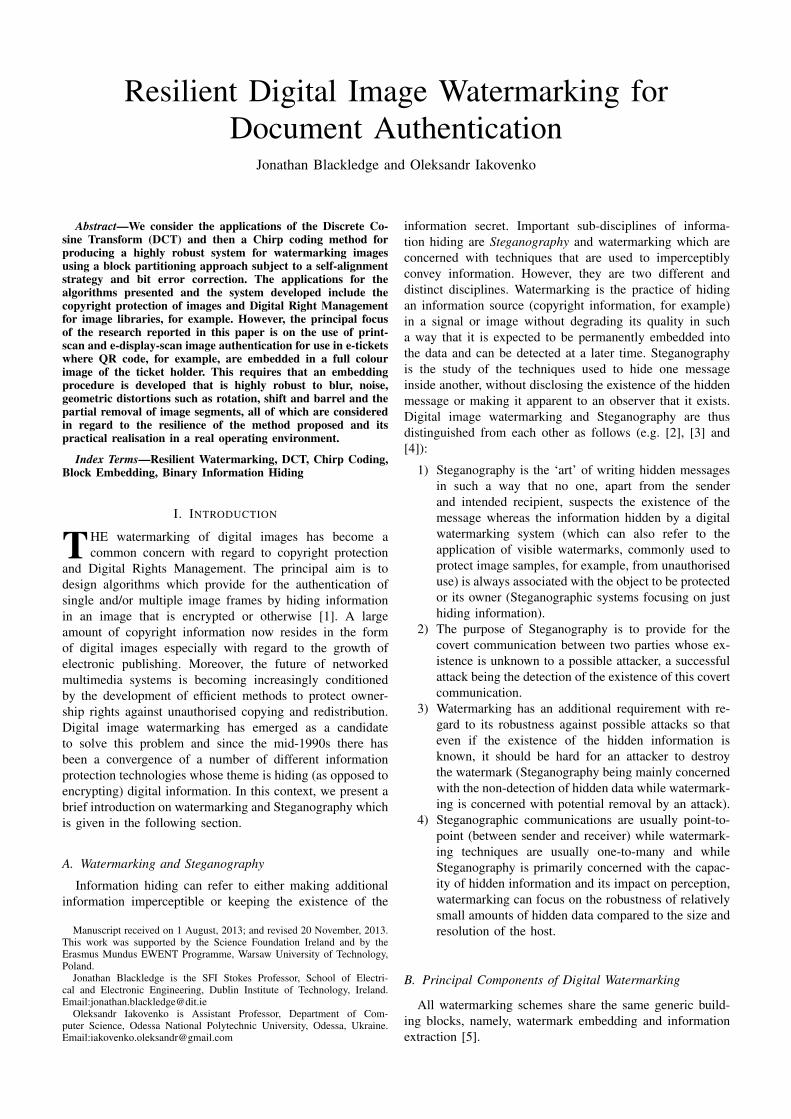
One of the principal methods for developing robust, asopposed to fragile watermarking algorithms, is to apply ablock embedding technique. This is because pixel-by-pixelembedding can be affected by virtually any digital andoptical image distortion. To overcome this problem someregions (blocks) of an image should be used for embeddingwatermark ‘symbols’ which, in practice, are numerical values(binary, integer or both) that code the information to beembedded. The idea of block embedding lies in splittingthe image into a number of blocks, and embedding hiddentext symbols into each block separately. The blocks may, inprinciple, be irregular, but block regularity is the norm. Toextract the watermark from the image, it is processed andanalysed block-wise. Each block of the image can have alimited number of permitted states and during applicationof the watermark extraction process, each block is analysedwith regard to its proximity to a defined state, the most likelystate then being accepted as one of the extracted symbols asillustrated in Figure 1.
Block embedding can yield a high level of robustness andcan cope with a modification to any pixel in an image blockas well as with some types of distortion or ‘attacks’ that arecommon to optical image transmission. These include thefollowing:
• image re-sampling and blur (typically a Gaussian blur);• barrel/pincushion and perspective distortion;• tone curve modification.
These properties allow us to consider not only digital imagedistortion but also natural optical image deformation. Thewatermark, which is robust to these deformations, can thenbe transmitted as an embedded code in the host imagethrough an optical channel. However, in order to enhancethe resilience of a watermark to the above, the quantity of
Fig. 1. During the extraction of a watermark, each image block is analysedwith regard to its proximity to four permitted states. The maximum likenesscriterion is used to determine the ‘closest’ state.
information that can be used in the watermark is reduced. Anumber of diverse block transform modification techniquescan be developed but in this paper we focus on DCTcoefficient modification and Chirplet block coding which canbe viewed in terms of a pattern addition process.
III. DCT COEFFICIENT EMBEDDING ALGORITHMS
The DCT produces a set of real coefficients that, on ablock-by-block basis can be modified to embed the water-mark data. In this section, we provide an overview of thealgorithm developed for this purpose. The algorithm has beendesigned with a specific focus on optimising performance interms of robustness to e-display-to-scan distortions where the(watermarked) image is captured using a low resolution mo-bile phone camera, for example. Compared to the applicationof the DCT for e-to-e watermarking scheme, this requiresthat the watermark is particularly robust to distortions ofnoise and blur which are discussed later in the paper. Thealgorithm developed assumes, by default, the use of full 24-bit colour images which provides greater ‘colour space’ forthe watermarking procedure than a grey level image and isused as part of the embedding process.
A. Outline of the DCT-based Watermark Embedding Algo-rithm
1) The host or container image Ic
is converted fromRGB to YCbCr colour mode. Only colour channels C
b
and Cr
are modified during the embedding processes.This is because embedding in a brightness channel ismore noticeable thereby requiring smaller amplitudesof perturbations.
2) Each colour channel is split into number of regularblocks of pixels B
B
k
(blue) and B
R
k
(Red), k =
1, 2, ..., L, each block being taken to be a matrix ofpixel values:
B = [b
i,j
] , i = 1, 2, ...,M, j = 1, 2, ..., N
The dimensions of each block (M and N ) are chosento keep the block shape as close to a square as possible.
3) The embedding data h is protected with an errorcorrection code, resulting in data extension:
h
0t
, t = 1, 2, ..., 2L

4) The two-dimensional Discrete Cosine Transform(DCT) is performed on each block:
X
m,n
=
M�1Pi=0
N�1Pj=0
b
i,j
cos
⇥⇡
M
�i+
1
2
�m
⇤cos
⇥⇡
N
�j +
1
2
�m
⇤,
where X
m,n
are the DCT spectrum components ofblock B
k
, m = 1, 2, ...,M, n = 1, 2, ..., N .5) DCT components of a block are then modified ac-
cording to one of a number of possible patterns and,for simplicity, the system design for two embeddingpatterns P
0
and P
1
is described. Each pattern replacessome of the DCT components with exact values andrepresents one bit of the embedded data h
0t
. For exam-ple:
P
0
: [X
4,6
= 0, X
6,4
= �A,X
10,8
= 0, X
8,10
= A]
P
1
: [X
4,6
= A,X
6,4
= 0, X
10,8
= �A,X
8,10
= 0] ,
where A is the amplitude of the spectral perturbationwhose specific value affects the watermark visibilityand system robustness characteristics. The choice ofthe exact embedding patterns has great significance onthe robustness and visibility of the watermark. Thepatterns are chosen in a way that makes the systemrobust to carrier image modification which is addressedlater on in this paper.
6) The two-dimensional Inverse Discrete Cosine Trans-form (IDCT) is performed on the perturbed spectrumX
0m,n
:B
0=
⇥b
0i,j
⇤= IDCT
�X
0m,n
�
7) The modified blocks B
0k
are concatenated in the samemanner as in the initial image forming new colourchannels C
0b
and C
0r
and these (modified) channelscombined with the intact lightness channel to producethe resulting watermarked image I0
c
which is convertedback to RGB colour space.
8) The watermarked image is saved in one of a numberof image storage formats, being insensitive to imagecompression settings with the exception of lowest qual-ity compression in lossy formats, such as JPEG. Thewatermarked image can then be printed or displayedon a monitor for application of the extraction processwhich is described in the following section.
B. Outline of the Watermark Extraction Algorithm
1) The watermarked image I0c
, displayed on a monitoror printed on paper, is captured on a digital camerawhere the average phone camera quality is taken to begenerally sufficient for extraction, the critical capturingdistance and orientation depending on a number ofparameters, including the embedding amplitude A,embedding patterns P , image size and number ofblocks L.
2) The image is aligned and cropped by any accessiblemeans to match the original image as discussed inSection III (A).
3) Conversion to YCbCr colour mode is performed withonly the colour channels C
b
and Cr
being analysed.4) Each channel is split into blocks B
k
as used in theembedding procedure discussed in the Section III (A).
5) The Discrete Cosine Transform is performed for eachblock:
X = [X
m,n
] = DCT (Bk
)
6) The spectrum of each block is then evaluated todetect the presence of each pattern. The most likelyidentifying pattern in each block yields one bit ofthe embedded data and for the embedding patternsdiscussed in Section III (A), each embedded bit isdetermined by:
h
0t
=
(0 if (X
8,10
�X
6,4
) > (X
4,6
�X
10,8
),1 otherwise.
7) The Recovered data h is then obtained from h
0, usingan error correction code.
In the following section, the principal results associatedwith a series of optical and numerical experiments are pro-vided that yield a quantitative assessment of the algorithmsin terms of the resilience of the watermark data to a rangeof attacks.
IV. EVALUATION OF THE DCT EMBEDDING ALGORITHM
We consider a container image Ic
shown in Figure 2 whichis a full 24-bit colour image and has a size of 500 ⇥ 500
pixels and where its colour channels Cb
and C
r
are split intok = 11⇥12 = 132 blocks each. The size of each block B
k
is40⇥44 pixels. This particular image is chosen as a test casebecause of its relative homogeneity and object-to-backgroundclarity thereby providing a quality control measure in termsof the visual impact of a watermark that is not prevalent withmore complex and textured container images. Figure 2 alsoshows a typical example of a screen shot obtained using amobile phone camera for the watermarked image displayedon an LCD exhibiting Moire fringes.
Fig. 2. Container image used for evaluation of the DCT embeddingalgorithms (left) and an example of a watermarked image obtained froman LCD screen using a mobile phone camera (right).
The embedding data h consists of 71 bits and afterapplication of error-correcting code BCH(255,71) the lengthof coded data is 255 bits [17]. This code is capable ofcorrecting up to 30 bit errors and more up-to-date codes suchas LDPC can be used to boost system efficiency. Takingeach block to carry one bit, the total number of availableembedding bits is 2L = 264. However, since 264�255 = 9,there are nine extra blocks in the lower right hand cornerof the image which are not affected by the watermarkingprocedure, five of these blocks belonging to C
b
and four to

the C
r
channel. On this basis, we consider the resilience ofthe algorithms presented in Section 3.1.1 and Section 3.1.2to the ‘attacks’ discussed in the following sections.
A. Robustness to Additive NoiseAs long as the system uses Forward Error Correction, the
Bit Error Rate is not an optimal parameter for performanceevaluation. The system is designed to be bit-error free andso an evaluation is focused on a relationship which connectserror robustness with watermark intensity, given that thewatermark is extracted properly. The robustness of the systemto noise is highly dependent on the embedding rate R whichrelates the spectral perturbation intensity to the originalspectrum intensity. The noise intensity is expressed in termsof the percentage of image intensity with measurementsbeing performed in the following manner: (i) the embeddingrate R is fixed; (ii) the noise intensity is raised until errorcorrection fails; (iii) the most intensive noise, allowing error-less extraction, is taken as a ‘reference marker’. The resultis shown in Figure 3 which includes an example of the mostintensive case of additive Gaussian noise that does not affectthe watermark data.
Fig. 3. Watermark noise robustness for different embedding rates R (left)and an example of a high noise rate corresponding to a case which doesnot affect the watermark data.
B. Robustness to a Gaussian BlurRobustness to image blurring depends on the particular set
of DCT-coefficients that are used in the embedding patterns.If the radius of a Gaussian blur, for example, is less thanthe scale of embedded detail, then the blur does not distortthe watermark providing extraction is good. However, whenthe radius is equal or larger than the scale of embeddeddetail this detail is dissipated in the blur and extractionbecomes impossible. A Gaussian blur with a pixel radius upto and including 12 allows for proper watermark extractionbut beyond this threshold the blur erases the watermark.However, this effect does not depend on the embedding rateR.
C. Robustness to Image ShiftShift robustness also depends on the specific embedding
coefficients. However, if the embedding patterns use the sameset of embedding frequencies (which is optimal for noiserobustness) then the spatial pattern P
s appears similar toit’s counter-pattern shifted in some direction as illustrated inFigure 4. While a 3 pixel shift is easily recovered, a 4 pixelshift, either vertically of horizontally, prevents successfulwatermark recovery, regardless of the embedding rate.
Fig. 4. Illustration of a shifted pattern which can be erroneously recoveredas a counter-pattern.
D. Robustness to ‘Barrel’ and Rotational DistortionsGeometric image distortions such as barrel, pincushion and
rotational distortions are tightly connected with image re-sampling and optical image deformation. These distortionsneed to be corrected in an image alignment procedure and theresults discussed in this section are devoted to illustrating thesystems reaction to improper alignment. Watermark recoveryis not disrupted by re-sampling and a major problem withbarrel/rotation distortions is the displacement of edge embed-ding blocks which appear shifted with regard to the recoveryprocedure. Neither barrel or rotational distortions dependupon the embedding rate R and a marginal barrel parametersuch as 3.0 · 10�5 and a rotation of less than ±0.85
� doesnot affect accurate watermark extraction. However, theseresults depend significantly upon the container image andembedding block sizes.
E. Robustness to Partial Removal of Image DataThe partial removal of an entire section of the watermarked
image will clearly lead to complete corruption of the wa-termark data in the same section. However, it is importantto evaluated the effect of this on watermark extraction overthe rest of the image. Figure 5 clearly illustrates that theeffect of removing data from a portion of the image (inthis example, the lower left-hand corner of the image) doesnot affect the remaining portion of the image with regard towatermark extraction whose performance characteristics arethe same with regard to the robustness criteria discussed inthe previous sections.
F. DCT-embedding applicability considerationsThe DCT coefficient embedding algorithm presented in
this paper depends (as with all algorithms) on the specificembedding pattern used and other algorithmic parameters.However, in the context of the focus on using a DCTbased approach to produce a highly resilient watermarkingmethod, we may conclude with some common conceptual

Fig. 5. Example of the bit-errors generated in both channels (right) by thepartial removal of a portion of the watermarked image (left). The rest of theimage on the right-hand-side is white indicating that there are no bit-errorsin the remaining portion of the watermark after extraction from the spoiledimage. Note that error correction coped with such a data modification, andwatermark was extracted error-less.
strengths and weaknesses. The strengths/weaknesses listedbelow are primarily concerned with the watermark robustnesscharacteristics and do not relate to watermark capacity orvisibility factors.
1) Strengths:1) Robustness to additive noise (with a proper set of em-
bedded patterns) and robustness to image re-sampling.2) Flexible visibility and robustness characteristics
through choice of different patterns and robustness toscaling (within certain limits).
2) Weaknesses:1) Sensitivity to image shifting.2) Sensitive to image blur (especially if the patterns
include high-frequency coefficients).The sensitivity to shift is one of the principal problems
associated with application of the DCT in general. Thoughpatterns can be isolated that have different spatial frequen-cies, noise robustness requires that a counter-pattern shouldbe as close as possible to an intensity-inverted initial pattern.But due to the periodic nature of DCT-component patterns,shifted patterns can be easily recovered as counter-patterns -see Figure 4. However, subject to the weakness listed above,the algorithm presented in this paper does provide a DCTbased watermarking method that is practically applicableto print/e-display-to-e-scan detection that is inclusive of(marker-independent) automatic alignment. To the best of theauthors knowledge, this is the first DCT-based algorithm ofits type that can be used in this way.
V. CHIRPLET BASED WATERMARKING
In this section, we report on the use of two-dimensionalChirplets for embedding binary data in digital images, which,to the best of the author’s knowledge, represents anotheroriginal contribution to the field. After briefly reviewingwhat chirplets are and the combinations available we studytheir optimisation with regard to Bit-Error-Rates. On thebasis of this study, new watermark embedding and extractionalgorithms are presented with a focus on the robustness ofthe approach to image distortion.
A. Chirplet pattern watermarkingThe applications of digital watermarking and information
hiding are well known and involve numerous approaches
based on both direct data modification (e.g. Least SignificantBit embedding) and transformation based modification usingthe Discrete Cosine and Wavelet transforms, for example.Methods of encoding the hidden information are also diverseand range from bit-for-bit encryption schemes to the useof Stochastic Diffusion [18]-[19]. With regard to bit streamencoding for embedding information in digital signals, ‘ChirpCoding’ [20]-[21] is the one of the most robust techniqueswith regard to distortion through additive noise. While thistechnique has been successfully applied to audio signal au-thentication and self-authentication problems [22] for DigitalRights Management in the audio post-production industry,its potential to image watermarking applications is not yetexplored. Image watermarking systems were offered, usingfull-image chirplet parameters embedding [23]-[24].
B. Chirplet CombinationsChirplets can be defined in a number of related but
strictly different forms, and, by combining these forms,different chirp coding methods can be developed. This isa central theme of the work reported here, and, in thefollowing sections, we introduced the one-dimensional andtwo-dimensional chirplet combinations that are available.
C. One-dimensional ChirpletsOne-dimensional chirps are swept-frequency co-sinusoidal
signals. In a linear chirp, for example, the frequency f ofoscillation is a linear function of time t, i.e. f(t) = f
0
+ kt
where f
0
is the carrier frequency and k is a constant thatdefine the extent of the chirp - the ‘Chirping Parameter’.‘Chirplets’ are time limited chirps or chirps of compactsupport characterised by a frequency range that sweeps fromsome minimum to some maximum value or vice versa.
In the time domain, a real chirplet can be defined as (forsome arbitrary constant ✓
0
)
x(t; f
0
, k, ✓
0
) =
(sin
cos
2⇡
✓f
0
t+
k
2
t
2
+ ✓
0
◆�
or in complex form, as
x(t;!
0
,↵,�) = exp[i(!
0
t+ ↵t
2
+ �)]
where ! is the angular frequency, ↵ = ⇡k and � = 2⇡✓
0
D. Two-dimensional ChirpletsOne-dimensional chirplets can be combined to produce
two-dimensional chirplets on a row/column by row/columnbasis to produce a matrix of essentially one-dimensionalchirplets. However, for applications to non-separable imageprocessing, it is preferable to use two-dimensional patternsinstead. This approach yields some significant advantages inthe robustness of chirplet watermarking which is a focus ofthe work presented in this paper as discussed later.
Since the application of the technique focuses on digitalimages, chirplets are used in discrete form in which theyappear as vectors of size N composed of consecutive streamof uniformly sampled real floating point numbers between�1 and +1 inclusively, i.e.
c ⌘ c
i
2 [�1, 1]8i = 1, 2, ..., N

We consider a N ⇥N matrix P formed from the dyadictensor product of the vector c to produce a two-dimensionalchirplet as given by the equation
P = c
Tc ⌘
0
BBB@
c
1
c
2
...c
N
1
CCCA�c
1
c
2
. . . c
N
�
=
0
BBB@
c
1
c
1
c
1
c
2
. . . c
1
c
N
c
2
c
1
c
2
c
2
. . . c
2
c
N
......
. . ....
c
N
c
1
c
N
c
2
. . . c
N
c
N
1
CCCA
However, the chirplet vectors elements used to constructequation P can be constructed in both a ‘forward’ and‘reverse’ order. This produces a total of four distinct two-dimensional chirplet patterns as given below:
P
1
= c
Tc (1)
P
2
= reverse(c)Tc (2)
P
3
= c
Treverse(c) (3)P
4
= reverse(c)Treverse(c) (4)
Fig. 6. Four distinct two-dimensional chirplet patterns associated withequations (1)-(4) (clockwise, respectively).
The operation ‘reverse’ denotes the reversal of the orderof the elements in the vector c used to construct the matrixP , i.e. if
reverse(c = {c1
, c
2
, ..., c
N�1
, c
N
})= {c
N
, c
N�1
, ..., c
2
, c
1
}
The patterns produced by these two-dimensional chirpletsas given by equations (1)-(4) as illustrated graphically inFigure 6. Each of these patterns can be used to assign twobits of information and as there are four possible embeddingpatterns it is possible to encode the four fundamental binarypairs 00, 11, 01 and 10.
E. Optimal Chirplet Combinations and Parameters
For information hiding applications, a set of embeddingpatterns is defined to represent different symbols associatedwith the embedded data. For binary information hiding, thepatterns, corresponding to 0 and 1, should be as separableas possible in order to maximise the robustness of thewatermarked host image subject to a range of distortions andperturbations. The embedding patterns for 0 and 1 should bedifferent in some way. For a chirplet signal, the term differentcan be ambiguous. Thus, if a chirplet c is considered to beforward, the reverse chirplet is obtained by:
• Value Inversion: �c;• Time reversal: reverse(c);• Time Reversal and Value Inversion: �reverse(c);
F. Optimal Chirplet Type Combinations: Robustness to Noise
To illustrate the principle of optimal chirplet combina-tions, we choose noise robustness as a criterion for chirpletseparability for the one-dimensional case. A stream of 3000random bits r (i.e. a stream of 1’s and 0’s) is generated andthree sequences of chirplet signals generated, one sequencecorresponding to each of the chirplet pairs described above.Thus we generate the signal
s =
3000
ki=1
c
i
⌘ c
1
k c2
k · · · k c3000
where
c
i
=
⇢c
forward
if ri
= 1
c
reverse
otherwise
and k denotes concatenation of the vectors c
i
Gaussian noise n is then added to each sequence wherethe Noise-to-Signal Ratio (NSR) (the ‘Noise Intensity’) istaken to be a multiple of the chirplet amplitude. Thus wegenerate the ‘noisy signal’
s
n
= s+NSRn
the problem now being to recover or ‘detect’ the bit stream,‘chirp coded’ in the vector s. The detection is performedthrough cross-correlation of the vector s
n
with two chirplets:
d
1
= s
n
? c
forward
d
2
= s
n
? c
reverse
where ? denotes the correlation sum. The correlation max-imums are then evaluated to detect each bit in the outputstream and by dividing the number of erroneous bits by 3000,the ‘Bit-Error-Rate’ (BER) is computed. The computationis repeated with different noise intensities which yield theresults shown in Figure 7 The results show that among thechirplet pairs possible, the pair with Time Reversal (the RedSignal given in Figure 7) shows considerably lower BERsfor different noise intensities compared to the other chirpletpairs used. The results is effectively the same for differentchirplet parameters (e.g. the ‘Chirping Parameter’). Thus,in the application of ‘Chirp Coding’ for hiding binary datain digital signals (e.g. [20], [25] and [21]), Time ReversedChirplet Pairs provide optimal performance. We now discussthe issue of optimising the chirplet parameters.

Fig. 7. Bit-Error-Rate (BER) as a function of the Noise Intensity (Noise-to-Signal Ratio) for three different chirplet pairs as indicated, namely, TimeReversal and Value Inversion, Value Inversion and Time Reversal.
G. Optimal Chirplet Parameters
Chirplets are signals which have following fundamentalparameters:
• Starting Frequency f
0
;• Terminating Frequency f
1
;• Type of frequency sweep: Linear, Quadric, Logarithmic,
etc.Given the set of target characteristics, some particular
chirplets can be considered optimal. Numerical experimentswere therefore conducted to define the optimum combinationof minf
0
and maxf
1
for a linearly frequency swept chirpletin terms of achieving maximum robustness to additiveGaussian noise with a Noise Intensity set to 20. For eachcombination of f
0
and f
1
> f
0
, the value of the BERwas computed using 2000 chirplet samples in a sequenceusing Time Reversed Chirplet Pairs. The resulting surfaceplot corresponding to the function BER(f
0
, f
1
) is shown inFigure 8.
The Figure shows that chirplet noise resiliency highlydepends on chirplet starting and ending frequencies (the BERdeviation is about 15%), especially on their sum f
1
+f
0
. Onthe basis of this surface plot, the optimum chirplet parametersyielding optimal robustness to noise can be obtained.
Having established some important numerical issues withregard to using chirplets for signal based bit informationhiding, we now consider the details associated with the prin-cipal algorithms used for watermarking (grey-level) digitalimages (with binary information) and assess the robustnessof the approach to a range of distortions. It is noted that thesame approach can be used for full 24-bit colour images bydecomposing them into their RGB (or YCbCr) components,details of which lie beyond the scope of this paper.
H. Watermark Embedding Procedure
The principal steps associated with the algorithm forembedding binary data in a grey-level image is as follows:
1) Open a Grayscale Container Image Ic
, which is takento be normalised, i.e. I
c
2 [0, 1] (working with imagesof size 500⇥ 500 pixels for ‘proof of concept’ only)
Fig. 8. Bit-Error-Rate (BER) as a function of f0 and f1 > f0 for TimeReversed Chirplet Pairs.
2) Prepare the data for embedding h which is composedof 25 groups, 2 bits in each group: h
k
= {b1
, b
2
},k 2 [1, 25].
3) Define the set of four chirplet patterns Pi
, i 2 [1, 4],each chirplet being composed of 100 ⇥ 100 elementsand where chirplet values lie in interval [�1, 1].
4) Generate the Embedding Data Array E be groupingtogether 25 chirplet patterns C
k
into one matrix asgiven by
E =
2
66664
C1
C2
C3
C4
C5
C6
C7
C8
C9
C10
C11
C12
C13
C14
C15
C16
C17
C18
C19
C20
C21
C22
C23
C24
C25
3
77775
where
Ck
=
8>><
>>:
P1
, if hk
= {0, 0};P2
, if hk
= {0, 1};P3
, if hk
= {1, 0};P4
, if hk
= {1, 1};
and as shown in Figure 9. Note that the size of E isequal to the size of I
c
but for arbitrary sizes of Ic
, Ecan be zero padded.
5) The Watermarked image W is then acquired by addi-tion of the Embedding Image, scaled with an Embed-ding Rate Factor R, to the Container Image, i.e.
W = Ic
+R · E
By changing the value of R, it is possible to find anoptimal trade-off between invisibility of the watermarkand robustness with regard to watermark extraction.Typical values for R lie between 0.01 (maximuminvisibility) and 0.07 (maximum robustness).
Embedding can also be accomplished with only one bitper pattern. In this case, only two from four possible two-dimensional chirplet patterns are used. The embedding ca-pacity associated with this approach is half (i.e. 25 instead of

Fig. 9. Embedding map E, consisting of 25 two-dimensional chirpletpatterns.
Fig. 10. Example of image with embedded watermark, R = 0.03.
50 bits) but it provides greater robustness and the EmbeddingRatio can be set to a lower value.
I. Watermark extraction
Chirplet pattern detection is performed in the same way asthe matching detection of any pattern, namely, through (two-dimensional) cross-correlation of the watermarked imagewith each of four embedding patterns, i.e.
Di
= W ? ? Pi
, i 2 [1, 4] (5)
where ?? denotes the two-dimensional cross-correlation sum.As with other matched filtering methods, if a region of theimage contains an embedded chirplet pattern which matches
the correlation kernel, then the central part of the cross-correlation surface has a distinct maximum showing thepresence of a matching pattern as illustrated in (Figure 11).This property allows us to perform two important operations:
• Make a decision with regard to the embedded patternbased on direct comparison.
• Detect the position of the centre of the embedding blockupon extraction of the watermarked channel, e.g. whenthe watermarked image has been subjected to shift, re-sampling and other deformations and distortions.
Fig. 11. Results of cross-correlating one region with four chirplet patterns.The bright spot in the centre of the top-left block indicates the presence ofthe first chirplet pattern in a region.
If we assume that the original block-by-block positioning isknown, then the extraction procedure can be formalised usingthe following steps:
1) The watermarked image W undergoes a two-dimensional cross-correlation (equation 5) with eachof the four embedding patterns used.
2) For each embedding region, only the central com-ponents of the correlation surface are stored. These‘central components’ can be defined in a number ofways, and a detection filter can also be implemented.In this work, the central components are defined as asquare 7⇥ 7 matrix extracted from the centre in eachblock of the correlation surface.Figure 12 shows these central components matrices foreach of 25 embedding blocks, every central componentmatrix obtained from cross-correlation of block withone of four embedding patterns.
3) Compute the average value of the central componentin each of the four central regions for each embeddingblock:
A
i
= M(Central part of Di
), i 2 [1, 4]
4) Compare the average values A
i
and locate the maxi-mum value together with its associated index i whichuniquely identifies h
k
.

Fig. 12. The central components generated by cross-correlating eachembedding region with each of four embedding patterns — see equation (5).
Given the basic steps above, we now explore the robust-ness of the watermarking method when the watermarkedimage is subjected to a range of distortions.
TABLE ISUMMARY OF RESULTS OBTAINED THROUGH THE NUMERICAL
EXPERIMENTS UNDERTAKEN TO ASSESS THE ROBUSTNESS OF THEMETHOD TO IMAGE DISTORTION USING THE FIVE CATEGORIES LISTED,
I.E. SHIFT, NOISE, BARREL, GAUSSIAN BLURRING AND ROTATION.
Type of Distortion BERNo Distortion 0.06Shift (By any Extent) 0.06Noise (Intensity)5 0.0610 0.0620 0.0640 0.0680 0.04160 0.06320 0.10Barrel (Distortion Intensity)0.5 0.121 0.20Gaussian Blur (Blur Radius)5 0.0610 0.0815 0.1020 0.16Rotate (CCW Degrees)1 0.122 0.18
J. Robustness to distortionTo quantify the practical viability of the proposed method,
a number of numerical experiments were conducted with theaim of measuring the actual watermark robustness charac-teristics given that the data watermarking and recovery pro-cesses are the same as in algorithms outlined in Sections V-Hand V-I. This included the following basic steps:
1) Distorting the watermarked image in some way, theexact types of distortions being listed in Table I.
2) Extracting a watermark from the distorted image usingthe watermark extraction algorithm described in V-I.
3) Comparing the embedded and extracted data and com-puting the Bit-Error-Rate.
The results are compounded in Table I. In some regions of theimage, hidden data is extracted with errors even when thereis no distortion. The cause of this lies in the nature of the‘container image’, some regions of which can contain somepronounced chirplet-like patterns themselves. However, anappropriate selection of chirplet parameters together with anadjustment of the Embedding Rate Factor R can diminishthis effect. Any shift in the image pixels can be detectedand thereby eliminated and the Noise Intensity is taken as apercentage of the image intensity.
While performing a barrel (pincushion) distortion, a newradius of each point r
n
is calculated from the old radiusr according to the equation r
n
= r + ar
3, where a is theBarrel Distortion Intensity (divided by 10
6). These resultsare achieved without correction with regard to recovering theinitial positions. However, it is noted that this correction cansignificantly improve robustness to these types of distortion.
VI. AUTOMATIC ALIGNMENT
Irrespective of the transformation and/or coding methodused for embedding (including the DCT transform and chirpcoding techniques reported in this paper), an error-less ex-traction of embedded data relies on proper image alignment,and, in this section we discuss a novel method for aligningthe image using the same watermark data. The idea is to usethe watermark to align the image before final extraction ofthe watermark itself.
If the container image Ic
is known, an alignment procedurevia the image contents can be performed. However, thisapproach introduces additional limitations on the watermark-ing system. A common solution to this problem lies in theaddition of special alignment markers on the image whichallow for automatic alignment. These markers can flag thefact that a watermark may be present in the image therebyinitiating a potentially successful attack. For this reason, theapproach described here does not rely on any additionalmarkers. This is because the presence of embedding patternsin the image blocks’ yields a DCT spectrum that, in effect,provides a set of hidden markers located at the centre of eachblock. This idea is compounded in the following procedure:
1) The embedding block patterns are extracted in imagespace starting with an empty spectrum X0 given by
X0
=
⇥X
0
m,n
⇤= 0
The embedding pattern P is added to X0 and the twodimensional IDCT is performed and repeated for allembedding patterns P
v
, v = 0, 1, ..., V � 1. Althoughthe total number of patterns used in the results reportedhere is V = 2, the system can use a larger number ofembedding patterns at the cost of lower robustness butincreased capacity. The spatial embedding patterns
P
s
v
= IDCT(X0
+ P
v
)
are rectangular image blocks which indicate the pres-ence of spectral patterns P
v
in the block spectrum.

2) For each of the colour channels of the input water-marked image C
b
and C
r
, cross-correlation is per-formed with each of the embedding patterns P
v
where,in the output ⇥ = [✓
x,y
], negative values are replacedby zeros, i.e.
(✓
v
)
x,y
=
((C
r
? ?P
s
v
)
x,y
if (Cr
? ?P
s
v
)
x,y
> 0,0 otherwise.
where ?? denoted the two-dimensional cross-correlation operation. All the results for a particularcolour channel are combined additively, i.e.
⇥ =
V�1X
v=0
⇥
v
3) The correlation results for both colour channels arealso added together, i.e. ⇥ = ⇥
b
+⇥
r
. The Character-istic Picture ⇥ has the same size as the Container Im-age and consists of multiple cross-correlations. Each ofthese results have a pronounced peak in the correlationsurface which locates the centre of each embeddingblock. A typical example of the output is shown on aFigure 13.
Using this procedure, coupled with some ‘intelligent filter-ing’ applied to ⇥, the correlation peaks can be used asmarkers for the automatic image alignment and thus realign-ment of an image, realignment being undertaken throughapplication of the Radon transform, for example [1].
Fig. 13. Example of Characteristic Picture ⇥ generated in the correlationsurface that identifies the blocks associated with the presence of thewatermark data.
A. Automatic alignmentFor the watermarking schemes described in this paper,
error-less watermark extraction is feasible only if the water-marked image is properly aligned and divided into blocks inthe same way as undertaken during the watermark embedding
process. This condition holds by default if the watermarkingsystem uses purely electronic image transmission. However,in case of optical image acquisition (which is the focus ofthe research reported in this paper), the image is consideredto have been acquired through optical-to-digital conversionfrom a digital camera or (digital) scanning sensor. In thiscase, the image can be distorted by a number of factors whichinclude:
• the image is rotated by some angle;• the image is scaled (it’s pixel dimensions depend on the
sensor resolution and depth of focus);• the image is generally larger than the area of interest
which contains watermarked image and needs to becropped and shifted to match the required form;
• the image often experiences noticeable amounts ofperspective distortion;
• during the photographic acquisition process, the imagecan also be distorted by wide-angle distortions.
As mentioned previously, knowledge of the embeddingpattern allows extraction of the embedding blocks’ centralpoints. This section described a new algorithm which per-forms automatic alignment of an acquired image based onthe Characteristic Picture ⇥, derived from it.
Knowledge of the container image Ic
is not necessary forautomatic alignment. Extraction of block centre positionsrelies on knowledge of the embedding patterns P
v
only andit is important to note that spatial patterns should be scaledto perform superior block centres extraction.
For automatic alignment, the extraction side only requiresinformation on the number of blocks in the image M
b
= mn
and configuration of these blocks within the image - the num-ber of blocks in column m and in row n. This informationunambiguously defines the Template Characteristic Picture⇥
T
which consists of m ⇥ n square blocks filled with zerovalues. In the centre of each block there is one element filledwith a maximum value (see Figure 14).
Fig. 14. Template Characteristic Picture ⇥T .
To automatically align the acquired image it must passthrough a set of procedures, the parameters of these proce-dures being derived from the Characteristic Picture ⇥. Theprocedures are designed in such a way as to yield a versionof ⇥ that is ‘closer’ to ⇥
T
leading to overlapping (withina certain deviation). When the procedures are complete, theacquired image I
a
undergoes the same set of procedures withthe same inputs as it’s characteristic picture ⇥ which leadsto alignment of the embedding blocks to ⇥
T
. As the positionof embedding blocks in ⇥
T
is known (and even controlled)the acquired image I
a
can be divided into it’s embeddingblocks and analysed via the extraction algorithm.
The set of alignment procedures consists of:• Image rotation compensation, which ensures that the im-
age appears in the same angular position as it was duringthe embedding operation which is a key procedure andshould be performed first.
• Scale and shift compensation where the image is scaledand shifted by both vertical and horizontal axes in sucha way that the centres of the embedding blocks coincidewith respective centres of ⇥
T
, the rest of Ia
then beingcropped.
• Perspective distortion compensation when the imageexperiences perspective distortions which are detectedand corrected.
• Barrel/pincushion compensation which occur when awide-angle distortion is present in the image, a counter-distortion procedure being used to neutralise this effect.
The basic order of the procedures proposed above, in par-ticular, the realisation of certain procedures, can be repeatedwith different parameters for optimisation. In the followingsections we describe the processing method associated witheach procedure. In each case, the distorted image I
a
and thetemplate characteristic picture ⇥
T
are the inputs and outputis the modified partially aligned image I0
a
.
B. Rotation compensation
The Characteristic Image ⇥ consists of a grid of correla-tion maxima (see Figure 13). In this case, the correct anglecan be evidently defined as the one in which correlationmaxima in a column are located one above another. Bysumming the lines of different picture rotations, the properangle can be automatically detected in terms of that anglehaving the most pronounced maxima of the sum.
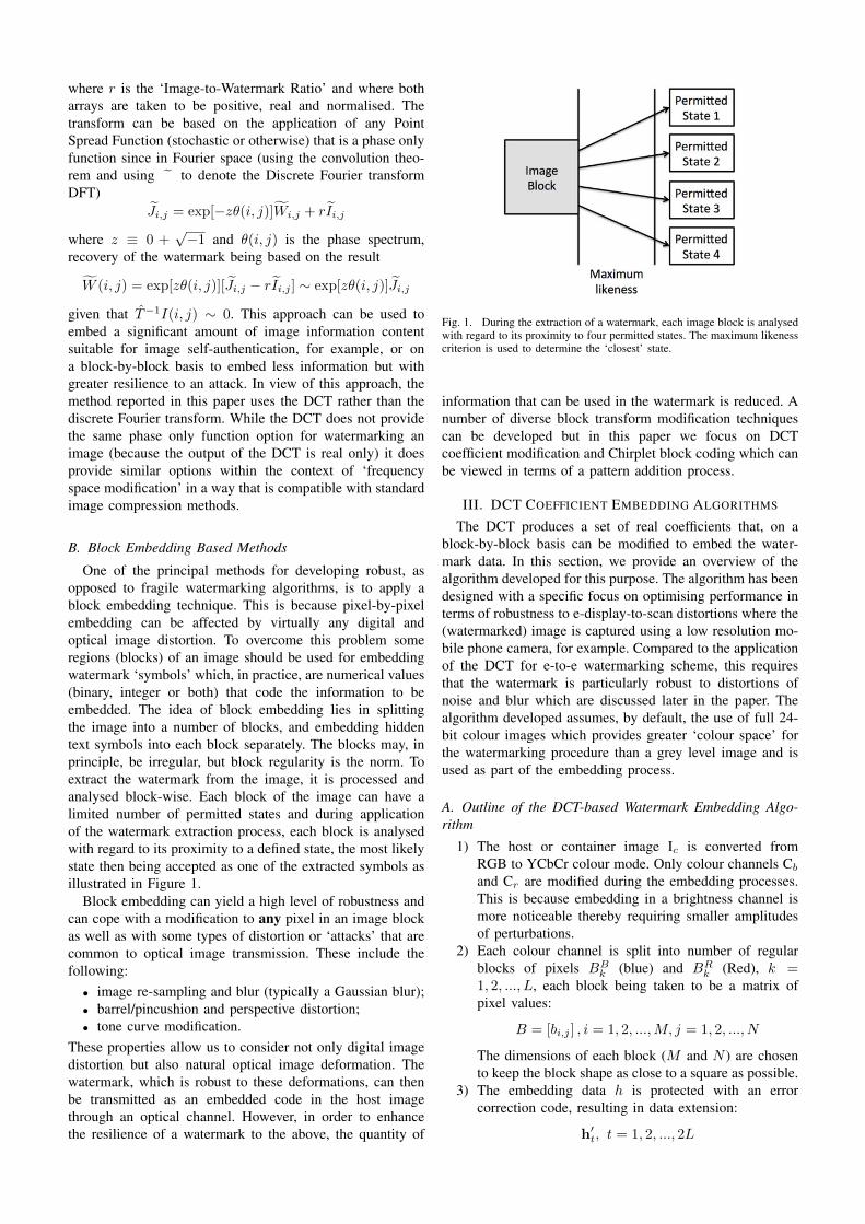
The Radon transform can be used to automate this proce-dure. It accepts a characteristic image ⇥ and an angle range�↵ as inputs and outputs an angle-dependant line sum R(see Figure 15):
R =
Z
L
⇥(x) |dx|
Each column in R corresponds to one particular angle ofrotation. The maximum element in R occurs in the columncorresponding to the optimal rotation compensation angle.When the compensation angle is known, rotation compensa-tion can be performed for the acquired image. After rotationcompensation, correlation maximums are located one abovethe other.
Fig. 15. Visualisation of Radon transform output R. Each column is aline sum for a given angle of rotation. The maxima indicate the columncorresponding to the rotation compensation angle.
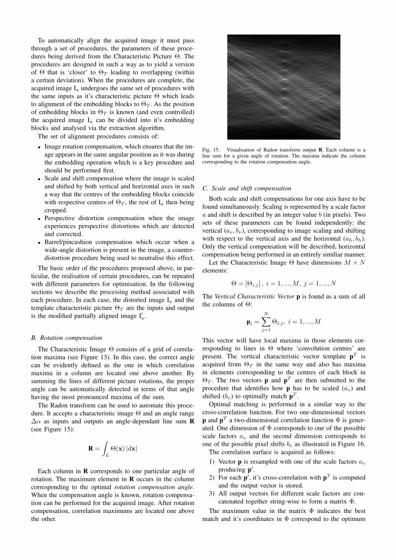
C. Scale and shift compensation
Both scale and shift compensations for one axis have to befound simultaneously. Scaling is represented by a scale factora and shift is described by an integer value b (in pixels). Twosets of these parameters can be found independently: thevertical (a
v
, b
v
), corresponding to image scaling and shiftingwith respect to the vertical axis and the horizontal (a
h
, b
h
).Only the vertical compensation will be described, horizontalcompensation being performed in an entirely similiar manner.
Let the Characteristic Image ⇥ have dimensions M ⇥N
elements:
⇥ = [⇥
i,j
] , i = 1, ...,M, j = 1, ..., N
The Vertical Characteristic Vector p is found as a sum of allthe columns of ⇥:
pi
=
NX
j=1
⇥
i,j
, i = 1, ...,M
This vector will have local maxima in those elements cor-responding to lines in ⇥ where ‘convolution centres’ arepresent. The vertical characteristic vector template pT isacquired from ⇥
T
in the same way and also has maximain elements corresponding to the centres of each block in⇥
T
. The two vectors p and pT are then submitted to theprocedure that identifies how p has to be scaled (a
v
) andshifted (b
v
) to optimally match pT .Optimal matching is performed in a similar way to the
cross-correlation function. For two one-dimensional vectorsp and pT a two-dimensional correlation function � is gener-ated. One dimension of � corresponds to one of the possiblescale factors a
v
and the second dimension corresponds toone of the possible pixel shifts b
v
as illustrated in Figure 16.The correlation surface is acquired as follows:1) Vector p is resampled with one of the scale factors a
v
producing p0.2) For each p0, it’s cross-correlation with pT is computed
and the output vector is stored.3) All output vectors for different scale factors are con-
catenated together string-wise to form a matrix �.The maximum value in the matrix � indicates the best
match and it’s coordinates in � correspond to the optimum
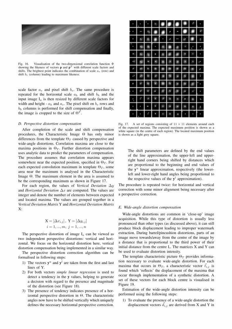
Fig. 16. Visualisation of the two-dimensional correlation function �showing the likeness of vectors p and pT with different scale factors andshifts. The brightest point indicates the combination of scale av (row) andshift bv (column) leading to maximum likeness.
scale factor a
v
and pixel shift b
v
. The same procedure isrepeated for the horizontal scale a
h
and shift b
h
and theinput image I
a
is then resized by different scale factors forwidth and height - a
h
and a
v
. The pixel shift on b
v
rows andb
h
columns is performed for shift compensation and finally,the image is cropped to the size of ⇥T .
D. Perspective distortion compensationAfter completion of the scale and shift compensation
procedures, the Characteristic Image ⇥ has only minordifferences from the template ⇥
T
caused by perspective andwide-angle distortions. Correlation maxima are close to themaxima positions in ⇥
T
. Further distortion compensationuses analytic data to predict the parameters of compensation.The procedure assumes that correlation maxima appearssomewhere near the expected position, specified in ⇥
T
. Foreach expected convolution maximum in template ⇥
T
, somearea near the maximum is analysed in the CharacteristicImage ⇥. The maximum element in the area is assumed tobe the corresponding maximum as shown in Figure 17.
For each region, the values of Vertical Deviation �y
and Horizontal Deviation �x are computed. The values areinteger and denote the number of elements between expectedand located maxima. The values are grouped together in aVertical Deviation Matrix Y and Horizontal Deviation MatrixX:
X = [�x
i,j
] , Y = [�y
i,j
]
i = 1, ...,m, j = 1, ..., n
The perspective distortion of image Ia
can be viewed astwo independent perspective distortions: vertical and hori-zontal. We focus on the horizontal distortion here, verticaldistortion compensation being implemented in a similar way.
The perspective distortion correction algorithm can beformalised in following steps:
1) The vectors yu and yl are taken from the first and lastlines of Y.
2) For both vectors simple linear regression is used todetect a tendency in the y values, helping to generatea decision with regard to the presence and magnitudeof the distortion (see Figure 18).
3) The presence of tendency indicates presence of a hor-izontal perspective distortion in ⇥. The characteristicangles now have to be shifted vertically which uniquelydefines the necessary horizontal perspective correction.
Fig. 17. A set of regions consisting of 11 ⇥ 11 elements around eachof the expected maxima. The expected maximum position is shown as awhite square (in the centre of each region). The located maximum positionis shown as a light grey square.
The shift parameters are defined by the end valuesof the line approximation, the upper-left and upper-right hand corners being shifted by distances whichare proportional to the beginning and end values ofthe yu linear approximation, respectively (the lower-left and lower-right hand angles being proportional tothe respective values of the yl approximation).
The procedure is repeated twice: for horizontal and verticalcorrection with some minor alignment being necessary aftera perspective correction.
E. Wide-angle distortion compensation
Wide-angle distortions are common in ‘close-up’ imageacquisition. While this type of distortion is usually lesspronounced than other types (as discussed above), it can stillproduce block displacement leading to improper watermarkextraction. During barrel/pincushion distortions, parts of animage move towards/away from the centre of the image bya distance that is proportional to the third power of theirinitial distance from the centre L. The matrices X and Y canbe used to evaluate distortion intensity.
The template characteristic picture ⇥
T
provides informa-tion necessary to evaluate wide-angle distortion. For eachmaxima that occurs in ⇥
T
, a characteristic vector ~
t
i,j
isfound which ‘reflects’ the displacement of the maxima thatoccur through implementation of a synthetic distortion. Aset of these vectors for each block centre is visualised inFigure 19.
Estimation of the wide-angle distortion intensity can beperformed using the following steps:
1) To evaluate the presence of a wide-angle distortion thedisplacement vectors ~
d
i,j
are derived from X and Y in

Fig. 18. Perspective distortion in an image is ‘reflected’ in a linearlydependent value of the vertical difference �y between the expected andactual positions of the maxima. The linear behaviour can be utilised bylinear approximation which numerically evaluates the presence of distortionin a robust manner.
the acquired image using the following equation
~
d
i,j
= (�x
i,j
,�y
i,j
)
2) To separate the wide-angle estimate from other typesof distortion, the vector ~
d
i,j
is projected onto the lineof ~t
i,j
using the equation
Ei,j
= |~di,j
|cos(��
i,j
),
where Ei,j
is an estimation of the barrel distortion inelement (i, j) and ��
i,j
is angle between ~
d
i,j
and ~
t
i,j
.3) The array E is sorted by increasing the distance L
i,j
between the centre of block (i, j) and the centre of thewhole Characteristic Image ⇥
T
.4) Only a part of the array E is used for analysis - E0
say, where Ei,j
2 E0 only if Li,j
� 2/3maxL. Thesevalues are located at the edge of ⇥ and demonstratebehaviour which is close to a linear function of L, seeFigure 20.
5) Simple linear regression is applied to approximate E0
to produce the linear parameters associated with shiftb and angle a. The Barrel Compensation Parameter isproportional to a and depends on size of ⇥
T
.
VII. EXPERIMENTAL EXAMPLE OF IMPLEMENTING THEAUTOMATIC ALIGNMENT AND RECOVERY METHODS
In order for the reader to appreciate the methodologyreported in the previous section, in this section we reporton some example results associated with an auto-alignmentand recovery experiment. This section describes the result ofimplementing the techniques discussed so far in this paper
Fig. 19. Effect of barrel distortion. Each block centre is visualised with avector ~ti,j showing the directions in displacement for the case of a barreldistortion. In the case of a pincushion distortion, the directions are opposite.
Fig. 20. Maxima displacement E0 as a function of distance from the centreof the image Li,j . The black squares represent actual values for differentpicture blocks. The red line represents those values acquired through linearregression.
with regard to evaluating the potential for developing an e-display/e-scan system.
We consider a container image Ic
which is a full-colourRGB image of size of 800 ⇥ 800 pixels. Three containerimages are used in the experiment as shown in Figure 21.The information capacity of the embedding data h is 256bits.
The experiment itself consists of following steps:1) The watermark is embedded in the colour channels.
Ic
is split into 8 ⇥ 8 square blocks of size 100 ⇥ 100
pixels each. Each block is converted to YCb
Cr
colourspace. Different chirplet patterns are embedded in theCr
and Cb
colour channels of a block, the embeddingprocedure and embedding patterns being described in

Fig. 21. Container images Ic: ‘Eagle’ (Left), ‘Lama’ (Centre) and‘Chameleon’ (Right).
Section V-H.2) The watermarked image W is saved and shown on a
laptop screen as shown in Figure 22.
Fig. 22. Watermarked images W: ‘Eagle’ for R = 0.1 (Left), ‘Lama’ forR = 0.2 (Centre) and ‘Chameleon’ for R = 0.1 (Right).
3) A set of photos of a laptop screen showing W is takenwith a phone camera. All the images acquired for thispurpose are obtained at slightly different angles anddistances and each image is treated separately as anacquired image I
a
(see Figure 23).
Fig. 23. Acquired images Ia - ‘Eagle’ (Left), ‘Lama’ (Centre) and‘Chameleon’ (Right).
4) The characteristic image ⇥ is acquired from Ia
as de-scribed in Section VI and the Chirplet coding methoddescribed in Section V-D used to construct the spatialembedding patterns P
s
v
, an example of the character-istic image being shown in Figure 24.
5) Automatic alignment of the acquired image Ia
is per-formed based on ⇥ as described in Section VI. Thealigned images are shown in Figure 25.
6) The watermark h
0 is extracted from the aligned imageIa
as described in Section V-I.7) The embedding data h and extracted watermark h
0 arecompared.
The experimental results are compounded in Table II.
VIII. SUMMARY AND CONCLUSION
The DCT coefficient embedding algorithm presented inthis paper depends (as with all algorithms) on the specificembedding pattern used and other algorithmic parameters.However, in the context of our focus on using a DCT based
Fig. 24. Example of a characteristic image ⇥ which is used for auto-alignment.
Fig. 25. Automatically aligned images - ‘Eagle’ (Left), ‘Lama’ (Centre)and ‘Chameleon’ (Right).
approach to produce a highly resilient watermarking method,we may conclude with some common conceptual strengthsand weaknesses. The strengths/weaknesses listed below areprimarily concerned with the watermark robustness charac-teristics and do not relate to watermark capacity or visibilityfactors. Strengths: (i) robustness to additive noise (with aproper set of embedded patterns) and robustness to image re-sampling; (ii) flexible visibility and robustness characteristicsthrough choice of different patterns and robustness to scaling(within certain limits). Weaknesses: (i) sensitivity to imageshifting; (ii) sensitive to image blur (especially if the patternsinclude high-frequency coefficients). The sensitivity to shiftis one of the principal problems associated with applicationof the DCT in general. Though patterns can be isolated, thathave different spatial frequencies, noise robustness requiresthat a counter-pattern should be as close as possible toan intensity-inverted initial pattern. But due to the periodicnature of DCT-component patterns, shifted patterns can beeasily recovered as counter-patterns. However, subject tothe weakness listed above, the algorithm presented in thispaper does provide a DCT based watermarking methodthat is practically applicable to print/e-display to e-scandetection that is inclusive of (marker-independent) automaticalignment. To the best of the authors knowledge, this is thefirst DCT-based algorithm of its type that can be used in thisway.
In order to develop a system that overcomes the weak-ness associated with application of the DCT, we have alsoconsidered a new approach that uses a special coding kernelbased on different chirplet forms as a binary data embeddingpattern. The unique properties of chirplets (as explored inthis work) allow for the achievement of very high ratesof robustness to image distortion especially with regard todistortion by noise. The main aim of this work has been

TABLE IIRESULTS OF AUTO-ALIGNMENT AND RECOVERY EXPERIMENT.
Ia BER, %Eagle1 16.4Eagle2 12.5Eagle3 9.4Eagle4 14.1Eagle5 11.7Lama1 3.9Lama2 5.4Lama3 5.4Lama4 29.7Lama5 25Chameleon1 0Chameleon2 0Chameleon3 0Chameleon4 60.9Chameleon5 0
to develop a set of numerical experiments to verify therobustness properties of the watermarking method and todefine a set of optimal chirplet parameters including bestestimates for the combination of minimum and maximumchirplet frequencies and optimal chirplet pairs for embeddingbinary data. The results show that chirplet pairs with timereversal provides significantly lower Bit-Error-Rates whencompared to other pairs. With regard to the application ofthe method to image watermarking application in general,the method is shown to be adequately robust to Barrel andRotational distortion (relatively to other image watermarkingmethods including the application of the Discrete Cosineand Wavelet transforms, for example) but highly robustto Blur and significantly robust to additive noise. In thelatter case, and, to the best of the authors knowledge andresearch, the method may prove to be the most resilient ofall image watermarking methods developed to date in termsof its robustness to noise. This is in keeping with previouswork undertaken on chirp coding [20] including the useof multi-level chirp coding [25] and a further investigationis therefore required into the application of chirplets forthe two-dimensional multi-channel watermarking of digitalimage using the methodology and applications discussed [26]and [27]. In this context, the procedures developed in thispaper are compounded in a new ‘Technology to License’[28].
ACKNOWLEDGMENTS
Jonathan Blackledge is supported by the Science Foun-dation Ireland Stokes Professorship Programme. OleksandrIakovenko is funded by the Erasmus Mundus Action IIco-operation and mobility programme EWENT (East-WestEuropean Network on Higher Technical education) managedby Warsaw University of Technology, Poland. Both authorsare very grateful to Dr Marek Rebow at Dublin Instituteof Technology for arranging the collaborative research pro-gramme being undertaken by the authors.
REFERENCES
[1] J. M. Blacklledge, Cryptography and Steganography: New Algorithmsand Applications. Centre for Advanced Studies Textbooks, WarsawUniversity of Technology, 2002.
[2] I. J. Cox, M. Miller, and J. Bloom, Digital Watermarking. Morgan-Kaufmann, 2002.
[3] R. J. Anderson and F. Petitcolas, “On the limits of steganography,”IEEE: Selected Areas in Communications, vol. 16, no. 1, pp. 474–481, May 1998.
[4] F. Petitcolas and M. Kuhn, “Information hiding: A survey,” IEEESpecial Issue on the Protection of Multimedia Content, vol. 87, no. 7,pp. 1062–1077, July 1999.
[5] C. T. Hsu and J. L. Wu, “Hidden digital watermarks in images,”Transactions of Image Processing, vol. 8, no. 1, pp. 58–68, 1999.
[6] J. Mintzer, F. Lotspiech and N. Morimoto, “Safeguarding digitallibrary contents and users,” D-Lib Magazine, December 1997.
[7] J. M. Blackledge, “Multi-algorithmic cryptography using deterministicchaos with application to mobile communications,” ISAST Trans. onElectronics and Signal Processing, vol. 1, no. 2, pp. 23–64, 2008.
[8] J. W. Yoon and H. Kim, “Multi-algorithmic cryptography usingdeterministic chaos with application to mobile communications,” Com-munications in Nonlinear Science and Numerical Simulation, vol. 15,no. 12, pp. 3998–4006, 2010.
[9] H. Liu and X. Wang, “Color image encryption based on one-timekeys and robust chaotic maps,” Computers and Mathematics withApplications, vol. 59, no. 10, pp. 3320–3327, 2010.
[10] G. Situ and J. Zhang, “Double random-phase encoding in the fresneldomain,” Optics Letters, vol. 29, no. 14, pp. 1584–1586, 2006.
[11] J. M. Blacklledge, Digital Image Processing: Mathematical and Com-putational Methods. Woodhead Publishing Series in Optical andElectronic Materials, 2005.
[12] J. Shen, “On wavelet fundamental solutions to the heat equation -heatlets,” Journal of Differential Equations, vol. 161, no. 1, pp. 403–421, 2000.
[13] G. Tsaur, “Constructing green functions of the schrodinger equation byelementary transforms,” American Journal of Physics, vol. 74, no. 7,pp. 600–606, 2006.
[14] J. M. Blackledge and O. Iakovenko, “On the application of two-dimensional chirplets for resilient digital image watermarking,” inProc. ISSC2013, vol. 24, 2013, pp. 1–8.
[15] J. M. Blackledge and A. R. Al-Rawi, “Application of stochasticdiffusion for hiding high fidelity encrypted images,” ISAST Trans. OnComputing and Intelligent Systems, vol. 3, no. 1, pp. 24–33, 2011.
[16] J. M. Blackledge, “Steganography using stochastic diffusion for thecovert communication of digital images,” IAENG International Journalof Applied Mathematics, vol. 41, no. 4, pp. 270–298, 2011.
[17] F. J. MacWilliams and N. J. A. Sloane, The Theory of Error-CorrectingCodes. North-Holland Publishing Company, 1977.
[18] J. M. Blackledge and E. Coyle, “e-fraud prevention based on the self-authentication of e-documents,” Conference on Digital Society, IEEEComp. Society, pp. 329–338, 2010.
[19] J. M. Blackledge and A. R. Al-Rawi, “Steganography using stochasticdiffusion for the covert communication of digital images,” IAENG Int.J. of Appl. Math., vol. 4, no. 4, pp. 270–298, 2011.
[20] J. M. Blackledge, “Digital watermarking and self-authentication usingchirp coding,” ISAST Trans. on Elec. & Sig. Proc., vol. 1, no. 1, pp.61–71, 2007.
[21] J. M. Blackledge and E. Coyle, “Self-authentication of audio signalsby chirp coding,” Proc. DAFx09, Como, Italy, vol. 12, no. 1, pp. 1–8,Sept. 2009.
[22] J. M. Blackledge, “Self-authentication of audio data forcopyright protection,” Technology to License, Dublin Instituteof Technology, July 2009. [Online]. Available: http://www.dit.ie/hothouse/technologiestolicence/availableforlicense/ict/
[23] D. Minghui and Z. Xiuli, “A robust digital image watermarking algo-rithm based on chirplet transform,” Intelligent Information Hiding andMultimedia Signal Processing (IIH-MSP), 2010 Sixth InternationalConference, pp. 86–89, October 2010.
[24] D. Minghui, Q. S. Zeng, and Y. Song, “Robust watermarking algorithmbased on time-frequency chirplet,” Advanced Materials Research, vol.179, pp. 881–885, 2011.
[25] J. M. Blackledge and O. Farooq, “Audio data verification and authenti-cation using frequency modulation based watermarking,” ISAST Trans.on Elec. and Sig. Proc., vol. 3, no. 2, pp. 51–63, 2008.
[26] J. M. Blackledge, A. R. Al-Rawi, and R. Hickson, “Multi-channelaudio information hiding,” Proc. DAFx2012, York University, pp. 309–316, September 2012.
[27] J. M. Blackledge and A. R. Al-Rawi, “Multi-channel digitalrights management for audio post-production,” Technology to License,Dublin Institute of Technology, August 2012. [Online]. Available: http://www.dit.ie/hothouse/technologiestolicence/availableforlicense/ict
[28] J. M. Blackledge and O. Iakovenko, “Two-dimensional chirpletsfor robust digital image watermarking,” Technology to License,Dublin Institute of Technology, June 2013. [Online]. Available: http://www.dit.ie/hothouse/technologiestolicence/availableforlicense/ict


![blackledge - capitulo 2[1]](https://img.dokumen.tips/doc/110x75/557201f94979599169a2b88a/blackledge-capitulo-21.jpg)


![[Digital Watermarking 01 & 02] Applications and Properties of Watermarking](https://img.dokumen.tips/doc/110x75/577d34c41a28ab3a6b8ecca2/digital-watermarking-01-02-applications-and-properties-of-watermarking.jpg)


