Embed Size (px)
Citation preview

Division of Solid Mechanics
ISRN LUTFD2/TFHF--05/5114--SE (1-47)
RESIDUAL STRESSES DUE TO WELDING OF A NOZZLE TO A PRESSURE VESSEL
Master’s Dissertation by
Linda Karlsson
Supervisors Nils-Gunnar Ohlson, Alfa Laval Tumba AB
Göran Whilborg, Div. of Solid Mechanics
Copyright © 2005 by Div. of Solid Mechanics, Alfa Laval Tumba AB, Linda Karlsson
For information, address:
Division of Solid Mechanics, Lund University, Box 118, SE-221 00 Lund, Sweden. Homepage: http://www.solid.lth.se

PREFACE
Preface Having completed more than 160 points of study in mechanical engineering it was time to complete my degree with a master’s thesis. This was performed at Alfa Laval Tumba AB with Nils-Gunnar Ohlson, Ph.D, scientist, Solid Mechanics Department, as supervisor, in cooperation with Göran Wihlborg, university lecturer, at the department of solid mechanics at LTH. I wish to thank my supervisors and other people who have helped me with my work. I would also like to express my gratitude to all those at Alfa Laval Tumba AB who made me enjoy my time there, especially Claes-Göran Carlsson, PhD, Manager, Fluid Dynamics & separation Technology, who introduced me into the floor ball and football teams.


ABSTRACT
Abstract Cracks have come up around nozzles that have been welded onto the housing of a number of separators, for instance the model OFPX717, also called LEO. These cracks may be due to residual stresses coming up after welding. Therefore the objective of this work is to determine these residual stresses. The residual stresses have been estimated numerically by the FE-method. The numerically calculated values have been compared with analytical and experimental analyses. The maximum value of the circumferential residual stresses is approximately the same as the yield stress no matter the size and shape of the pressure vessel and pipe, whereas the radial residual stresses are different with different geometry. For steel 2333 with pipe radius 100 mm and hemispherical pressure vessel with radii ranging between 500 and 1500 mm the maximum value of the radial residual stresses varies between 60 and 88 % of the yield stress. Sammanfattning Det har uppstått sprickor kring insvetsade rör på ett antal separatorer, till exempel på modellen OFPX717 även kallad LEO. Dessa sprickor kan bero på restspänningar, som har uppstått efter svetsning. Det här arbetets syfte är att bestämma dessa restspänningar. För att beräkna restspänningarna har FE-programmet NISA använts. Dessa värden har jämförts med analytiska och experimentella analyser. Både töjningsexperimentet och NISA simuleringarna resulterade i tangentiella spänningar i storleksordning sträckgränsen oavsett geometrin, medan de radiella spänningarna varierar beroende på geometri. Med ett rör med radien 100 mm och tryckkärl med radierna 500 till 1500 varierar den maximala radiella spänningen mellan 60och 88 % av sträckgränsen.

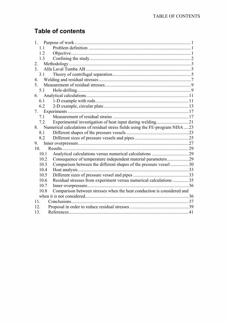
TABLE OF CONTENTS
Table of contents 1. Purpose of work .....................................................................................................1
1.1 Problem definition .........................................................................................1 1.2 Objective ........................................................................................................1 1.3 Confining the study........................................................................................2
2. Methodology ..........................................................................................................3 3. Alfa Laval Tumba AB ...........................................................................................5
3.1 Theory of centrifugal separation....................................................................5 4. Welding and residual stresses ................................................................................7 5. Measurement of residual stresses...........................................................................9
5.1 Hole-drilling...................................................................................................9 6. Analytical calculations.........................................................................................11
6.1 1-D example with rods.................................................................................11 6.2 2-D example, circular plate..........................................................................13
7. Experiments .........................................................................................................17 7.1 Measurement of residual strains ..................................................................17 7.2 Experimental investigation of heat input during welding............................21
8. Numerical calculations of residual stress fields using the FE-program NISA ....23 8.1 Different shapes of the pressure vessels ......................................................23 8.2 Different sizes of pressure vessels and pipes...............................................25
9. Inner overpressure................................................................................................27 10. Results..............................................................................................................29
10.1 Analytical calculations versus numerical calculations ................................29 10.2 Consequence of temperature independent material parameters...................29 10.3 Comparison between the different shapes of the pressure vessel ................30 10.4 Heat analysis ................................................................................................33 10.5 Different sizes of pressure vessel and pipes ................................................33 10.6 Residual stresses from experiment versus numerical calculations ..............35 10.7 Inner overpressure........................................................................................36 10.8 Comparison between stresses when the heat conduction is considered and when it is not considered..........................................................................................36
11. Conclusions......................................................................................................37 12. Proposal in order to reduce residual stresses ...................................................39 13. References........................................................................................................41


PURPOSE OF WORK
1. Purpose of work Alfa Laval was founded in the late 19th century by Gustav de Laval and Oscar Lamm, as a result of de Laval’s development of the continuous centrifugal separator. The separators have many applications, such as separation of oil and water and cleaning industrial fluids in the manufacturing industry, and a great number of food applications. The best know is the one for milk. The heart of the separator is the rotating bowl. It is enclosed in a housing, which sometimes is exposed to an internal pressure. Pipes and nozzles are connected to the housing by welding. At times cracks have appeared around the pipes on certain separators, for instance on a model named OFPX717, also known as LEO. These cracks developed while the separator was in use and are likely caused by fatigue, although external loads were considered in design. After welding residual stresses always appear. These are, however, not considered by the design rules. Instead it is assumed that the safety factor accounts for their presence.
1Asstim
1TS
Figure 1.1 Separator OFPX717 after it has been repaired and cracked for the second time
.1 Problem definition s mentioned above, the residual stresses are assumed to be accounted for by the
afety factor. However, this approach only works for a certain level of residual tresses. The residual stresses may be larger than expected, weakening the material, so hat it no longer holds for the same amount of load. Therefore the scope of this work s to estimate these stresses. In order to make the simulations more time-effective the odels used for stress calculations may be simplified in different ways.
.2 Objective he main objective of this work is to estimate the residual stresses caused by welding. tress field comparison will be made on the following basis
• Different shapes of pressure vessel. • Different sizes of pressure vessel and pipes.
1

PURPOSE OF WORK
1.3 Confining the study The housing consists of cylindrical and conical parts, and the pipes may be connected to any part of the housing in different angles. However, in this study the housing is modelled either as a cylinder or as a hemispherical head and the pipe is connected at right angle. The housing is in this work considered to be a pressure vessel. The heat affected zone is assumed to develop symmetrically around the pipe. The method of welding and the added weld mass is not considered, so the only affect from welding consist of the associate heat input. This study will not consider any would-be defects in the vicinity of the welds, so no fracture mechanics evaluations will be made. Investigating crack development may very well be an important matter, but is left out. Also, the most important limitation in this report should be emphasized, namely, the assumption that the weld will be able to transfer load as soon as its temperature has dropped below a certain value, and its ability of load bearing will be established all around the pipe at the same time. Residual stresses caused by welding are very difficult to simulate, so it is important to compare the results from analytical and numerical calculations with experimental results.

METHODOLOGY
2. Methodology Simulations of the stress development during solidification and cooling of welds were made in the FE-program NISA. Element sizes and shapes, and number of nodes were chosen to optimise, to the best of my ability, accuracy and time-efficiency. The results from the simulations were compared with analytical calculations and experiments. Experiments comprised measurement of residual strains in the housing by the means of stress relief by hole-drilling on one hand and measuring temperature versus time during welding on the other hand. Residual stresses were analytically derived from the residual strains. Information from similar work has been obtained and evaluated. In this work radial and circumferential stresses in pressure vessels are computed. These directions relate to the pipe and they follow the shape of the pressure vessel, see Figure 2.1. Both membrane and bending stresses are included. To be able to account for these, the stress components in the outermost, middle and innermost layers were collected from the output files. They are denoted by “o”, “m” and “i”, respectively.
Figure 2.1 The radial, r, and circumferential, c, directions
3


ALFA LAVAL TUMBA AB
3. Alfa Laval Tumba AB Alfa Laval is market leader in the fields of separation, heat exchangers and fluid handling technology. In Sweden there are about 2000 employees and 450 of them work in Tumba. The department of separation development is located in Tumba about 20 km south west of Stockholm. Alfa Laval was established in 1883, but was at that time called AB Separator. AB Separator was formed by Gustaf de Laval and Oscar Lamm, as an answer to de Laval’s development of his continuous centrifugal separator, at that time unique in the world. The first continuous separator was, however, used for industrial applications in Norway, separating fish oil already in 1882. de Laval’s first separator had a capacity of 130 litres per hour and operated at a speed of 500 rpm. The separators of today operate at a speed of several thousands rpm. In 1889 a German named Clemens von Bechtolsheim invented the conical discs that were installed in the separator bowl for improving separator efficiency. The name of the company changed to Alfa-Laval in 1963. The word “alfa” comes from the conical alpha discs, whose cone angle was denoted by α. The hyphen was removed 20 years later.
3.1 Theory of centrifugal separation If a glass of muggy water stands still for a while it may become clear, if the mugginess is due to the presence of heavier solid particles, which eventually sink to the bottom. When the water is clear it can be poured off, decanted like wine, leaving the solids at the bottom. The time required for this process depends on the setting speed and the distance to the bottom. High speed and short distance results in a quick separation. The setting speed is determined by the viscosity of the liquid and gravitation force according to Stokes’ law. To increase the speed of separation the force on the particles may be increased. This is done by the centrifugal force due to rotation. By rotating the bowl in the separator a centrifugal force will pull the particles or the heavier liquid phase outwards in the same as manner the gravitation pulls them downwards. The faster the bowl rotates the greater the centrifugal force. Separating efficiency can be increased hundred- or thousand-folds. Stokes’ law:
( )µ18
12 SSgdv −=
v = setting velocity, d = particle diameter, S-S1 = density difference, µ = viscosity, g = gravitation
alpha discs
Figure 3.1 part of a separator with alpha-discs
5

ALFA LAVAL TUMBA AB
To further increase the separation speed, thin plates can be placed as is shown in Figure 3.1. In this way the distance which the heavier phase must travel to reach a “bottom” is shortened, and the conical form allows the particles or the heavier liquid to slide down the plates. These plates were originally referred to as alpha discs. The separation procedure may be run continuously by letting the so-called feed (liquid that is to be treated) flow continuously into the bowl and at the same time removing the solids as well as the separated liquid phases. Pipes are therefore connected to the housing – the pressure vessel – of the separator.

WELDING AND RESIDUAL STRESSES
4. Welding and residual stresses Residual stresses are stresses locked in a component and exist without any external loads. They may arise at any time during the components life cycle and always appear to some extent during fabrication operations such as casting, rolling or welding (1). The residual stresses are always balanced within a component or assembly with compressive stresses at some places and tensile at others. This can be visualized with springs. When one part is compressed another part is always extended. However, opposed to the springs, residual tresses work in three dimensions. Sometimes compressive residual stresses may be introduced intentionally to strengthen components, but tensile residual stresses may severely reduce the durability of the component. Although the component does not crack solely due to the residual stresses they add to stresses from external loads. Hence, residual stresses lessen the strength of the material. An example of mechanically induced residual stresses is the spokes on a bicycle. The spokes are aligned radially and tightened, making them pull the rim inward. Due to that, compressive stresses appear in the rim and the hub is pulled outward. If the spokes were not tightened the bicycle would not support the load of the biker (2). One of the most significant causes of tensile residual stresses is welding. Since the high temperature makes the material yield and become stress free tensile stresses appear during the cooling phase. The maximum value of the tensile stresses is equal to the yield stress. Those large tensile stresses are counter balanced by compressive stresses elsewhere in the component reducing the buckling strength. By choosing appropriate materials, welding sequences, welding techniques and parameters the residual stresses may be minimized. Residual stresses are difficult to measure, especially without destroying the component. Therefore it is a great advantage if they can be predicted. This may be made by numerical computations, but is computationally difficult. The best and most reliable way of removing residual stresses is probably a stress-relief heat treatment. This method utilizes the fact that the yield stress decreases with increased temperature. Thus, the residual stresses can be reduced by temporarily heating up the material. However, heat treatment cannot always be performed on parts. It has been shown that in welded plates with no lateral constraint the longitudinal stresses are much larger than the transversal ones (3). The longitudinal stresses do not significantly depend on the longitudinal thermal gradient. However, the stresses at the ends of the weld differ from the rest. The black thick line in the middle of the plate in figure 4.2 is the weld. The longitudinal direction is along the weld line, and the transversal direction is perpendicular to the weld line.
7

WELDING AND RESIDUAL STRESSES
Lateral sides
Figure 4.1 welded plate One way to minimize residual stresses after welding may be to choose the optimal welding sequence. Tso-Liang et al. (4) have examined the effect of different welding sequences when welding one small circular plate inside the hole of a larger circular plate. The examined welding sequences are progressive welding, backstep welding and jump welding, see Figure 4.2. The circumferential stresses do not differ significantly between different welding sequences, but the radial stresses becomes slightly smaller with backstep welding, due to the post-weld heat treatment and pre-heating effect. The stresses do not considerably differ in the circumferential direction.
F
Backstep welding
Progressive welding
Jump welding
igure 4.2 The various welding sequences
Weld line

MEASUREMENT OF RESIDUAL STRESSES
5. Measurement of residual stresses
5.1 Hole-drilling The idea is that the change in strain is measured when a hole is drilled in the component containing residual stresses. With knowledge of the strain difference before and after the hole was drilled the residual stresses can be derived. Drilling holes with various depths can be used to survey the change of residual stresses at various depths underneath the surface. This is the least destructive of mechanical methods and can give results quite fast (5). The residual stress is evaluated point wise. The strain may be measured using photoelasticity, brittle-coating, or electrical strain gauges. The result is normally analysed using Kirsch’s hole-type solution, and usually the assumption that the boundary conditions are far away from the hole is made.
9

ANALYTICAL CALCULATIONS
6. Analytical calculations Very few problems concerning multi-axial residual stress fields can be solved by analytical means, in particular if non-linear material properties are involved. In order to better understand the results from numerical computations it may be helpful to consider some simple problems using analytical calculations.
6.1 1-D example with rods Two rods are connected in parallel with their upper ends being fixed. The lower end of rod no. 1 is attached to a rigid yoke. The second rod is shorter, see Figure 6.1. The short rod, rod no. 2, is uniformly heated until it reaches the yoke and is attached to it by welding. With both rods attached to the yoke the rods are stress free. From this stress free state rod no. 2 is cooled down to ambient temperature. No heat dissipated to rod no. 1. It is assumed that the temperature change is large enough to result in plastic strains in at least on of the rods. The two rods are made of the same material and perfect plasticity is assumed. Which stresses and strains will appear?
ACYTTeACT TEP D
W
Figure 6.1
bbreviations: ross-sectional areas A1 and A2
ield stress yieldσ hermal expansion coefficient α emperature when plasticity begins in ither of the rods during the cooling phase Tpmbient temperature T0 urrent temperature T emperature when rod no.2 reaches the yoke Tmax
he following solution starts when the temperature has risen to Tmaxquilibrium: 1 + P2 = 0 (1)
isplacement condition: 21 εε = (2)
hile linear elastic, Hooke’s law predicts that
11

ANALYTICAL CALCULATIONS
E1
1σε = ; ( TT
E p −+= ασ
ε 22 ) (3)
One obtains
( )
( )21
22
21
21
AAATTE
AAATTE
p
p
+
−=
+
−−=
ασ
ασ
(4)
Three cases may be distinguished as for when plastic deformation will occur. Case 1) 21 AA <
( pyieldyield TTEA
A−+==== 0
121
2
121 ; ; α
σεεσσσσ )
with temperature independent material parameters:
( ) 02
21 TTE
−+== ασ
εε
Case 2) 21 AA >
EAA
yieldyield1
2121
21 ; ; σ
εεσσσσ ====
Case 3) 21 AA =
( )pyield TTE
−+==== 01
2121 ; ασ
εεσσσ
with temperature independent material parameters
( )TTE
−+== 02
21 ασ
εε
Numerical example For further investigation of this, figures are used in the equations above. E = 200 GPa; yieldσ = 200 MPa; α = 1.5*10-5 ºC-1; Tmax = 220ºC; T0 = 20ºC
Case 1) 21 A21A =
0025.0 MPa; 100 MPa; 200 2121 −===−= εεσσ Plastic strain encountered in 1, εp = -0.0015
Case 2) A1 = 2A2
0005.0 MPa; 200 MPa; 100 2121 −===−= εεσσ Plastic strain encountered in 2, εp = 0.0015
Case 3) A1 = A2 = A 002.0 MPa; 200 MPa; 200 2121 −===−= εεσσ
Plastic strain encountered in 1, εp = -0.001 It may be remarked that temperature dependent material parameters always affect the strains but affect the stresses only if neither of the rods reaches plasticity.

ANALYTICAL CALCULATIONS
6.2 2-D example, circular plate We shall now investigate how stresses develop in the immediate surrounding of the nozzle in the pressure vessel, by considering a model where the pressure vessel has been simplified to a circular plate with a hole. The circular plate is considered infinite with the hole radius being r0. It is regarded thin in the sense that the plane stress is assumed. An area from the hole to a radius of x*r0 has been heated from welding. When that part is cooling down it is assumed stress free at 500 ºC. The analysis is linear elastic and no heat conduction is assumed. Two cases have been analysed; one with the inner boundary of the plate constrained to no displacement – corresponding to a very stiff pipe – and one with a stress free inner boundary simulating a very weak pipe. The temperature distribution is obviously discontinuous, and thus the stresses in the heated zone and the zone not affected by the heat must be derived as separate. The part being heated is called no. 1 and the rest is called no. 2, which is denoted with subscripts. The equations used were taken from ref. (6).
( )
( ) ( )
( ) ( )
( )rr
r
r
z
r
Eru
drrrTrI
rTr
rIErBA
rrIE
rBA
νσσ
σ
ασ
ασ
φ
φ
−=
=
=
⎟⎠⎞
⎜⎝⎛ −++=
−−=
∫0
0
22
22
(5)
The temperature distribution for stress free plate after welding is as follows
⎩⎨⎧
≥≤≤
=0
000
r* x ,0r*xrr ,
rT
T
In order to compute the residual stresses, been solved, namely,
⎩⎨⎧
≤≤≤−
=r
TT
0
000
xr ,0xrrr ,
Boundary and equilibrium conditions Both cases
Figure 6.2 Pressure vessel simplified to circular plate with a hole
(6)
an equivalent thermo elastic problem has
(7)
13

ANALYTICAL CALCULATIONS
( ) ( )( ) ( )0201
0201
2 0)(
xrxrxruxru
ru
rr σσ ==
=∞→ (8 a)
Stiff pipe 0)( 01 =ru (8 b)
Weak pipe 0)( 01 =rrσ (8 c)
The analytical solutions for both cases are the same, namely:
( )⎪⎪⎩
⎪⎪⎨
⎧
<−
≤≤⎟⎟⎠
⎞⎜⎜⎝
⎛−
=
,12
,12
02
2
200
002
200
rxrxrrET
xrrrrrET
rα
α
σ (9)
( )⎪⎪⎩
⎪⎪⎨
⎧
<−
≤≤⎟⎟⎠
⎞⎜⎜⎝
⎛+
=
rxrxrrET
xrrrrrET
02
2
200
002
200
,12
,12
α
α
σφ (10)
ασσ
ασσ
φφ ETrx
ETxrrr
00max
20
0max
)(
112
)(
==
⎟⎠⎞
⎜⎝⎛ −==
(11)

ANALYTICAL CALCULATIONS
Radial stress, x = 1.08
0
0,02
0,04
0,06
0,08
0,1
1 1,5 2r/r0
σ/(E
αT0)
Circumferential stress x = 1.08
-0,1
0,1
0,3
0,5
0,7
0,9
1,1
1 1,2 1,4 1,6 1,8 2r/r0
σ/(E
αT0)
Maximum radial stress
0
0,1
0,2
0,3
1,0 1,2 1,4x
σ/(E
αT0)
Maximum circumferential stress
0
0,2
0,4
0,6
0,8
1
1,2
1 1,2 1,4 1,6 1,8 2x
σ/(E
αT0)
Figure 6.3 The radial stress and circumferential stress as a function of normalized radius r/r0, and the maximum value of the radial stress for various values of the heated zone size x.
15


EXPERIMENTS
7. Experiments Two experiments have been performed for this work. One experiment where the residual strains around a pipe welded to a pressure vessel were measured and one where the temperature was measured during welding.
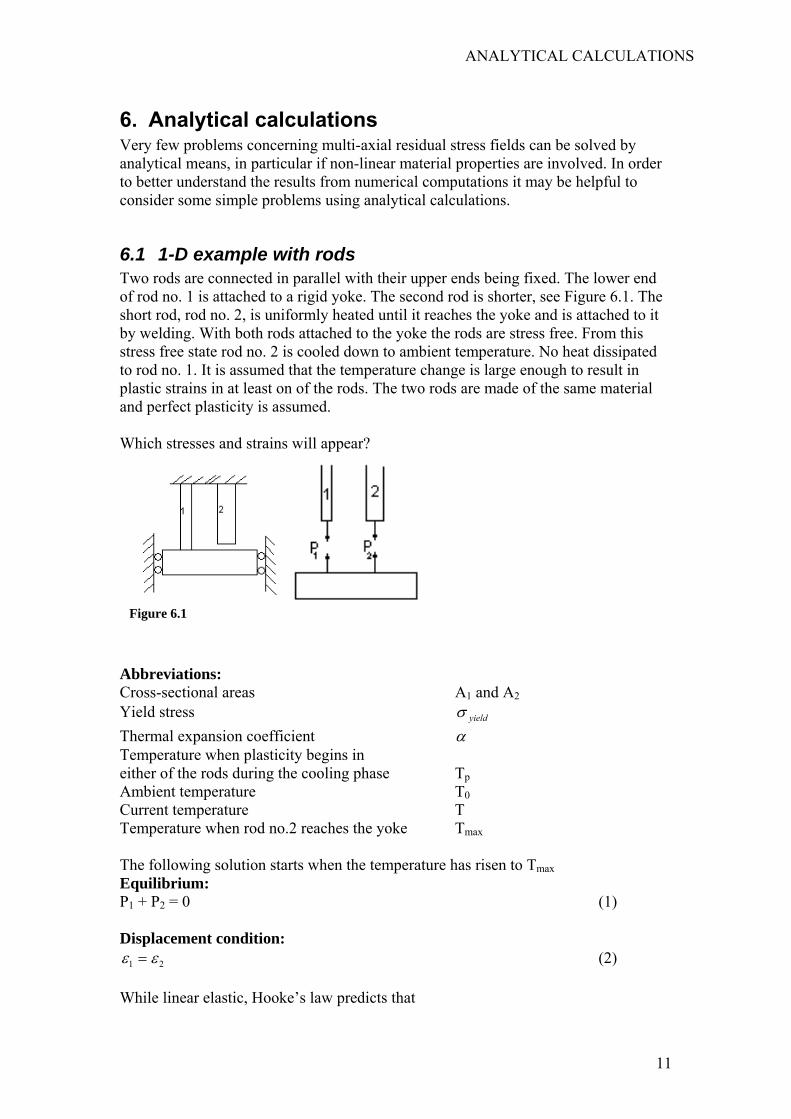
7.1 Measurement of residual strains As is mentioned in chapter 5 there are different ways to measure residual strains. In this experiment the hole-drilling method has been used, and the strains were measured with strain gauges. The experiment resulted in strain values in the radial direction at five points. Two of them circumferentially and radially located at the same place, but on the inner and the outer surfaces respectively. The strain gauges are numbered as shown in Figure 7.2. No. 4 is hidden in the figure behind the pipe. In place no. 4 the strain was measured on both the outer surface and the inner surface, denoted a and b respectively. The other three are only on the outer surface. Strain gauge Residual strain (µstr.)1 -436 2 -617 3 -591 4a -316 4b -143 These measured residual strains show that they differ depending on where, in the circumferential direction, they were measured. Here the residual stresses will be derived for point no. 4, since the strains have been measured on both the inside and the outside, giving the opportunity to include bending stresses. The bending stresses and membrane stresses are added as is shown in Figure 7.1.
ARCrcppttrd
Figure 7.1 Membrane stresses plus bending stresses in the plate. h is the thickness of the plate
bbreviations: adial stress rσ ircumferential stress φσ
adial strain rε ircumferential strain φε art from bending in inner surface subscript i art from bending in outer surface subscript o hickness of plate platehhickness of pipe pipehadius of hole and pipe a istance from hole centre to strain gauge 1.4a
17
EXPERIMENTS
Since only the radial strain was measured the circumferential strain is eliminated in the equations through eq. 12
( )
(rr
r
rr
E
εεν
Eσ
εεν
Eσ
ενσσ
ν
ν
φ
φφ
φ
=−
+−
=
+−
=
2
2
1
1
) (12)
Membrane part of the strThe bending stresses are co
Figure 7.3 The pipe and plate
The deflection, δ, of the piFigure 7.3 and Figure 7.4 a
Figure 7.2 This is the model on which the radial strains have been measured.
ess nsidered in next section
pe and the radial re
Figure 7.4 Deflection of pipe. The pipe is considered infinitely long
displacement, u, of the plate according to

EXPERIMENTS
( )
)cos(2
)( 30
rr
x
pipepipe
Eru
xeD
Tx
νσσ
κκ
δ
φ
κ
−=
= −
(13)
where
( )( )
4 22
2
2
3 13 ;112 ah
EhD
pipepipe
pipepipe
νκν
−=
−= (14)
T0 is force/length unit Boundary conditions
)()(
)( 0
auohTaplate
r
=
=
δ
σ (15)
Solution: Eq. 13 and 15 give
( rpipepipe
plater
Ea
Dh
νσσκ
)σφ −=32
(16)
Eq. 16 and 12 give
νεσσ
νε
νν
κσ
φrr
r
pipepipe
plater
E
EaD
Eh
−=
−=⎟⎟⎠
⎞⎜⎜⎝
⎛−+
12 3
(17)
Bending stresses: Indices o and i for outer and inner surfaces respectively.
riro
riro
riiri
rooro
E
E
εεσσ
ενσσ
ενσσ
φ
φ
−=−=
=−
=−
(18)
Combining eq. 12 and 17 yields oi φφ εε −= (19)
Ө shown in figure 7.6 is derived according to ref (7)
( )( ) ( )
( )( ) ( )rbaD
MMbabaD
rMaMbr 2212
22
221
22
2
11)(
−−−
+−+
−=
ννθ
19
EXPERIMENTS
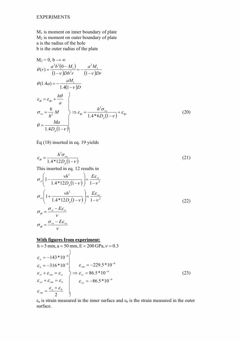
M1 is moment on inner boundary of plate M2 is moment on outer boundary of plate a is the radius of the hole b is the outer radius of the plate M2 = 0, b → ∞
( )( ) ( )
( )DaMa
DrMa
rDbMbar
νθ
ννθ
−−=
−−=
−−
=
14.1)4.1(
110)(
1
12
21
22
( )
( ) op
roi
p
ro
oi
Dh
DMa
Mh
ah
φφ
φφ
εν
σε
νθ
σ
θεε
+−
=⇒
⎪⎪⎪
⎭
⎪⎪⎪
⎬
⎫
−=
=
+=
16*4.1
14.1
6 3
2 (20)
Eq (18) inserted in eq. 19 yields
( )νσεφ −
=112*4.1
3
p
roi D
h (21)
This inserted in eq. 12 results in
( )
( )
νεσσ
νεσσ
νε
νσ
νε
νσ
φ
φ
roroi
ririi
ro
pro
ri
pri
E
E
ED
vh
ED
vh
−=
−=
−=⎟
⎟⎠
⎞⎜⎜⎝
⎛
−+
−=⎟
⎟⎠
⎞⎜⎜⎝
⎛
−−
2
3
2
3
1112*4.11
1112*4.11
(22)
With figures from experiment:
0.3 GPa, 200 E mm, 50 a mm, 5 h ==== ν
⇒
⎪⎪⎪⎪
⎭
⎪⎪⎪⎪
⎬
⎫
+=
=+=+
−=
−=−
−
2
10*316
10*1436
6
barm
brmro
armri
b
a
εεε
εεεεεε
ε
ε
6
6
6
10*5.86
10*5.86
10*5.229
−
−
−
−=
=
−=
ro
ri
rm
ε
ε
ε
(23)
εa is strain measured in the inner surface and εb is the strain measured in the outer surface.

EXPERIMENTS
membrane stresses σr = 30 MPa, σΦ = 253 MPa bending stresses σro= -19 MPa, σri=19 MPa, σΦ= 6 MPa, σΦi= -6 MPa, total stresses in inner and outer surfaces σro= 11 MPa, σri=49 MPa, σΦo= 259 MPa, σΦi= 247 MPa,
Figure 7.5 Deformation of plate and pipe. At point no. 1 is εφo and at point 2 is εφi.
1.4a
7.2 Experimental investigation of heat input during welding A small piece of a pipe was placed into the hole of a plate. The plate corresponds to the part of the pressure vessel surrounding the pipe. Electric arc welding was started in one point and continued until the pipe was fully attached to the plate. On this plate four thermocouples were mounted. Two of them were mounted one cm from the pipe and the other two were connected two cm from the pipe. The thermocouples recorded the temperature versus time. These curves were used to estimate the heat input in the melt, which is used in chapter 8.2. for the numerical stress analyses.
Temperature curves
0
100
200
300
400
500
600
700
800
0 10 20 30 40t (s)
T (º
C)
1 cm from pipe2 cm from pipe
Figure 7.2 temperature curves from experiment. T-room temperature
21

EXPERIMENTS
NUMERICAL CALCULATIONS OF RESIDUAL STRESSES USING THE FE-PROGAM NISA
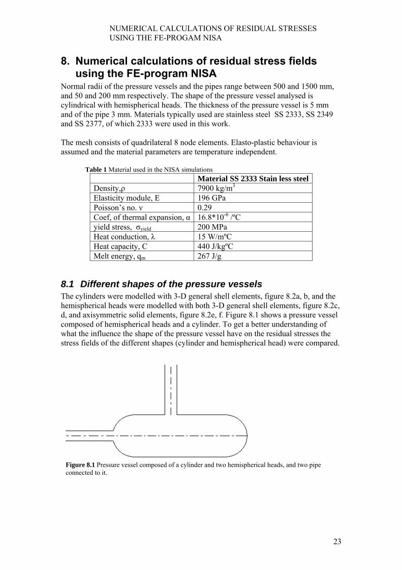
8. Numerical calculations of residual stress fields using the FE-program NISA
Normal radii of the pressure vessels and the pipes range between 500 and 1500 mm, and 50 and 200 mm respectively. The shape of the pressure vessel analysed is cylindrical with hemispherical heads. The thickness of the pressure vessel is 5 mm and of the pipe 3 mm. Materials typically used are stainless steel SS 2333, SS 2349 and SS 2377, of which 2333 were used in this work. The mesh consists of quadrilateral 8 node elements. Elasto-plastic behaviour is assumed and the material parameters are temperature independent.
Table 1 Material used in the NISA simulations Material SS 2333 Stain less steel Density,ρ 7900 kg/m3
Elasticity module, E 196 GPa Poisson’s no. ν 0.29 Coef, of thermal expansion, α 16.8*10-6 /ºC yield stress, σyield 200 MPa Heat conduction, λ 15 W/mºC Heat capacity, C 440 J/kgºC Melt energy, qm 267 J/g
8.1 Different shapes of the pressure vessels The cylinders were modelled with 3-D general shell elements, figure 8.2a, b, and the hemispherical heads were modelled with both 3-D general shell elements, figure 8.2c, d, and axisymmetric solid elements, figure 8.2e, f. Figure 8.1 shows a pressure vessel composed of hemispherical heads and a cylinder. To get a better understanding of what the influence the shape of the pressure vessel have on the residual stresses the stress fields of the different shapes (cylinder and hemispherical head) were compared.
Figure 8.1 Pressure vessel composed of a cylinder and two hemispherical heads, and two pipe connected to it.
23

NUMERICAL CALCULATIONS OF RESIDUAL STRESSES USING THE FE-PROGAM NISA
Figure 8.2 a-f) The 3-D models are shown with first principal stresses and the axisymmetric model is shown with radial stresses.
b
ac
f
ed

NUMERICAL CALCULATIONS OF RESIDUAL STRESSES USING THE FE-PROGAM NISA
Figure 8.3 The red part is the heated zone When comparing the different shapes no heat conduction is assumed. Instead the heat is dissipated by other means. The yield strength at 500 ºC is low enough to ensure a stress free state. Therefore in NISA the temperature in the heated zone is cooled from 500 ºC. In figure 8.3 the heated zone is shown as red. The mass being heated and what temperature is reached depends on energy input by welding and material parameters C and λ. Furthermore, the energy input depends on voltage, V, current, I, and time, t. V, I and t are assumed to be 20 V, 80 A and 150 s respectively. The time is chosen since it takes about two and a half minutes to weld around the pipe.
kJ 240** == tIVE To analyse the amount of mass being heated by that amount of energy the volume in Figure 8.3 and steel 2333 were considered. The radius of the hole in the pressure vessel and the outer boundary of the pipe is 0.1 m, and the inner radius of the pipe is 0.097 m. According to figure 8.1 a) the mass heated is equal to
kg 32.07900*)003.0*008.0*2*0985.0005.0*008.0*2*104.0( =+ ππ the amount of energy needed to heat that mass to 1000 ºC is
kJ 40.811000*440*32.0 === mCTEh and the amount of energy needed to melt that mass is
kJ 6.107390*276 === mqE mm the total amount of energy to both melt and heat that mass to 1000 ºC is
kJ 4.248=+= mhtot EEE which is approximately the same as the assumed energy input.
8.2 Different sizes of pressure vessels and pipes The different sizes of pressure vessels and pipes were compared only for the axisymmetric hemispherical heads. In this comparison the heat conduction is considered, and adiabatic condition is assumed. In the experiment explained in chapter 7.2 the temperature versus time in certain points were measured. For these stress calculations the temperature curves at more points were needed. To obtain that, a calculation in NISA was carried out where the heat energy input was regulated, so
25

NUMERICAL CALCULATIONS OF RESIDUAL STRESSES USING THE FE-PROGAM NISA
that the temperature curves at one and two centimeters from the hole coincided with the curves from the experiment. The temperature curves from this calculation were used.

INNER OVERPRESSURE
9. Inner overpressure As mentioned in the introduction, the cracks develop during the usage of the separator. Therefore the stresses arising in the housing, due to inner over pressure are calculated in NISA. This is carried out in an axisymmetric hemispherical head. Normal pressure is 0.6 MPa The results are in chapter 10.7
Figure 9.1 NISA-model with inner overpressure
27


RESULTS
10. Results
10.1 Analytical solutions versus numerical calculations The stress fields from the analytical solution are very close to the ones from NISA-simulation as can be seen below. The maximum radial stress depends only on the ratio between the radius of the hole and the radius to which was heated. When changing the radius of the pipe keeping the same extent of the heated area, the radial stress field changes too.
Circular plate with a hole
0,00
0,02
0,04
0,06
0,08
0,1 0,2 0,2
r (m)
σ/EαT
0
NISAanalytic
Circumferential stress
-0,3
0
0,3
0,6
0,9
1,2
0,1 0,15 0,2
r (m)
σ/(E
αT0)
NISAAnalytic
Figure 10.1 comparison between analytical calculations and NISA-simulations of a circular plate. The model in NISA has an outer radius of 800 mm. The difference is due to the limited extension of the plate in the NISA-simulation.
10.2 Consequence of temperature independent material parameters
The one-dimensional problem in chapter 6.1 implies that the residual stresses do not differ significantly whether the material parameters are temperature dependent or constant. This does also apply to the pressure vessels with the pipes. Figure 10.3 shows a comparison of the NISA simulation with temperature dependent and independent material parameters. The difference is very small, and the assumption that the material parameters are temperature independent is therefore adequate.
29

RESULTS
1
Tmdh1
E-modulus and yield stress
50
90
130
170
210
0 200 400 600Temp ºC
σyield stress, MPaE-modulus, GPa
Figure 10.2 E-modulus and yield stress when temperature dependent for SS 2333
F
0
ha
ise0
Comparison between stresses for temperature dependent and independent material parameters
Radial stresses
-0,50
-0,30
-0,10
0,10
0,30
0,50
0,00 0,01 0,02 0,03 0,04 0,05
r (m)
σ/σ
yiel
d
Circumferential stresses
-1,5
-1
-0,5
0
0,5
1
1,5
2
0,00 0,02 0,04
r (m)
σ/σ
yiel
d
dep idep mdep oind iind mind o
igure 10.3 Comparison between temperature dependent and independent material parameters
.3 Comparison between the different shapes of the pressure vessel
e maximum value of the circumferential stresses is always about the yield stress no tter the shape, size or material. The oscillation of stresses near the temperature continuity is due to lack of precision. The circumferential stresses in axisymmetric mispheric heads with radius of 500 and 1000 mm and with a pipe with a radius of 0 mm are shown in Figure 10.4.

RESULTS
HtahmntIs
Circumferential stresses
-1,5
-1
-0,5
0
0,5
1
1,5
2
0 0,01 0,02 0,03 0,04
r (m)
σ/σ
yiel
dR = 500 iR = 500 oR = 1000 iR = 1000 o
Figure 10.4 The tangential stresses in axisymmetric hemispheres in the inner and outer surfaces. Radius of pipe is 100 mm and radii of the pressure vessels are 500 and 1000 mm respectively.
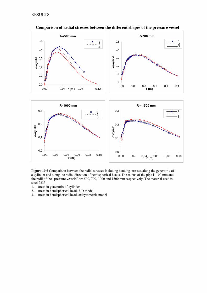
owever, the radial stresses do differ with different geometries. The comparison of he stresses on the cylinders and the hemispherical heads shows that the stress fields long the generatrix of cylinders are of the same order of magnitude as those on the emispherical heads, and the stress fields along the arcing are of the same order of agnitude as those on a plate. This implies that the arcing in the radial direction does
ot significantly affect the magnitude of the stresses, but the arcing perpendicular to he radial direction does. The directions of arcing are explained in Figure 10.5 n Figure 10.6 and Figure 10.7 the distribution of the radial residual stresses can be een.
Figure 10.5 The directions of arcing. a is arcing in the radial direction and b is arcing perpendicular to the radial direction. The radial, r, and circumferential, c, directions relate to the pipe and follow the shape of the pressure vessel as in figure 2.2.
31
RESULTS
Comparison of radial stresses between the different shapes of the pressure vessel
R=500 mm
0,0
0,1
0,2
0,3
0,4
0,5
0,00 0,04 0,08 0,12r (m)
σ/σ
yiel
d
123
R=700 mm
0
0,1
0,2
0,3
0,4
0,5
0,0 0,0 0,0 0,1 0,1 0,1r (m)
σ/σy
ield
123
R=1000 mm
0,0
0,1
0,2
0,3
0,00 0,02 0,04 0,06 0,08 0,10r (m)
σ/σ
yiel
d
123
R = 1500 mm
0,0
0,1
0,2
0,3
0,00 0,02 0,04 0,06 0,08 0,10r (m)
σ/σy
ield
123
Figure 10.6 Comparison between the radial stresses including bending stresses along the generatrix of a cylinder and along the radial direction of hemispherical heads. The radius of the pipe is 100 mm and the radii of the “pressure vessels” are 500, 700, 1000 and 1500 mm respectively. The material used is steel 2333. 1. stress in generatrix of cylinder 2. stress in hemispherical head, 3-D model 3. stress in hemispherical head, axisymmetric model
RESULTS
126
1Sdhwprf Th
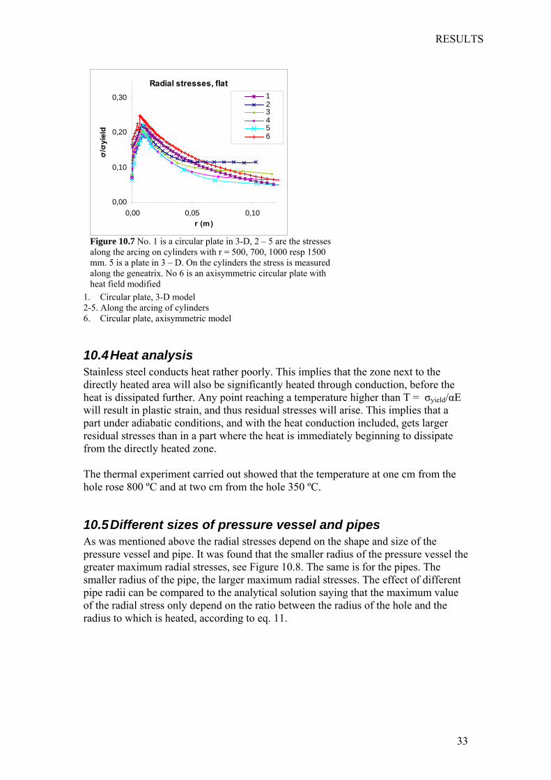
1Apgspor
Radial stresses, flat
0,00
0,10
0,20
0,30
0,00 0,05 0,10r (m)
σ/σ
yiel
d123456
Figure 10.7 No. 1 is a circular plate in 3-D, 2 – 5 are the stresses along the arcing on cylinders with r = 500, 700, 1000 resp 1500 mm. 5 is a plate in 3 – D. On the cylinders the stress is measured along the geneatrix. No 6 is an axisymmetric circular plate with heat field modified
. Circular plate, 3-D model -5. Along the arcing of cylinders . Circular plate, axisymmetric model0.4 Heat analysis tainless steel conducts heat rather poorly. This implies that the zone next to the irectly heated area will also be significantly heated through conduction, before the eat is dissipated further. Any point reaching a temperature higher than T = σyield/αE ill result in plastic strain, and thus residual stresses will arise. This implies that a art under adiabatic conditions, and with the heat conduction included, gets larger esidual stresses than in a part where the heat is immediately beginning to dissipate rom the directly heated zone.
he thermal experiment carried out showed that the temperature at one cm from the ole rose 800 ºC and at two cm from the hole 350 ºC.
0.5 Different sizes of pressure vessel and pipes s was mentioned above the radial stresses depend on the shape and size of the ressure vessel and pipe. It was found that the smaller radius of the pressure vessel the reater maximum radial stresses, see Figure 10.8. The same is for the pipes. The maller radius of the pipe, the larger maximum radial stresses. The effect of different ipe radii can be compared to the analytical solution saying that the maximum value f the radial stress only depend on the ratio between the radius of the hole and the adius to which is heated, according to eq. 11.
33

RESULTS
Ra
Fm
Radial stresses on outer surface
-0,8
-0,4
0
0,4
0,8
0 0,05 0,1 0,15 0,2
r (m)
σ/σ
yiel
dR = 500R = 700R = 1000R = 1500
Figure 10.8 Radial stresses. Radii of pressure vessels ranging between 500 and 1500 mm. All of them with a pipe radius of 100 mm.
adial stresses in hemispherical parts of pressure vessels, radii ranging between 500 nd 1500 mm, with a pipe with a radius of 100 mm
R = 500 mm
-1
-0,5
0
0,5
1
0 0,05 0,1 0,15 0,2
r (m)
σ/σ
yiel
d
inner surfacemiddle layerouter surface
R = 700 mm
-0,8
-0,4
0
0,4
0,8
0 0,05 0,1 0,15 0,2
r (m)
σ/σ
yiel
d
inner surfacemiddle layerouter surface
R = 1000 mm
-0,8
-0,4
0
0,4
0,8
0 0,05 0,1 0,15 0,2
r (m)
σ/σ
yiel
d
inner surfacemiddle layerouter surface
R = 1500 mm
-0,8
-0,4
0
0,4
0,8
0 0,05 0,1 0,15 0,2
r (m)
σ/σ
yiel
d
inner surfacemiddle layerouter surface
igure 10.9 Radial stresses on hemispherical pressure vessels, radii ranging between 500 and 1500 m, with a pipe with a radius of 100 mm.

RESULTS
Circumferential stresses in hemispherical parts of pressure vessels, radii ranging between 500 and 1500 mm, with a pipe with a radius of 100 mm
R = 500 mm
-1
-0,5
0
0,5
1
1,5
0 0,1 0,2 0,3
r (m)
σ/σ
yiel
d
inner surfacemiddle layerouter surface
R = 700 mm
-1
-0,5
0
0,5
1
1,5
0 0,05 0,1 0,15 0,2
r (m)
σ/σ
yiel
d
inner surfacemiddle layerouter surface
R = 1000 mm
-1
-0,5
0
0,5
1
1,5
0 0,05 0,1 0,15 0,2
r (m)
σ/σ
yiel
d
inner surfacemiddle layerouter surface
R = 1500 mm
-1
-0,5
0
0,5
1
1,5
0 0,05 0,1 0,15 0,2
r (m)
σ/σ
yiel
dinner surfacemiddle layerouter surface
Figure 10.10 Circumferential stresses on pressure vessels, radii ranging between 500 and 1500 mm, with a pipe with a radius of 100 mm.
10.6 Residual stresses from experiment versus numerical calculations
The residual stresses derived from the measured strains were, according to chapter 7.1, estimated to membrane stresses σr = 30 MPa, σΦ = 253 MPa bending stresses σro= -19 MPa, σri=19 MPa, σΦ= 6 MPa, σΦi= -6 MPa, total stresses in inner and outer surfaces σro= 11 MPa, σri=49 MPa, σΦo= 259 MPa, σΦi= 247 MPa, The high circumferential stress implies that the measured point is in a highly heated zone. The radial stress is tensile both on the inner and the outer boundary respectively. This is the case for the numerical calculations, in a small span, where the heat conduction is considered, which can be seen in figure 10.11.
35

RESULTS
10.7 Inner overpressure The inner overpressure results in rather low stresses both in radial and circumferential directions, see graphs below.
1
Wcwat
Fw
Circumferential stresses from pressure
0,15
0,2
0,25
0 0,2 0,4 0,6 0,8
r (m)
σ/σ
yiel
d
inner surfacemiddleouter surface
Radial stresses from pressure
-0,05
0
0,05
0,1
0,15
0,2
0,00 0,20 0,40 0,60 0,80
r (m)
σ/σ
yiel
d
inner surfacemiddleouter surface
Circumferential stresses from pressure
0,15
0,2
0,25
0 0,2 0,4 0,6 0,8
r (m)
σ/σ
yiel
d
inner surfacemiddleouter surface
Figure 10.11 Stresses in the pressure vessel due to inner pressure
0.8 Comparison between stresses when the heat conduction is considered and when it is not considered
hen the heat is assumed to be dissipated by other means than through heat onduction, as when the different shapes of the pressure vessels are compared in this ork, the residual stresses are lower than when the heat conduction is considered and
diabatic conditions are assumed. This implies that the result is not conservative when he heat conduction is not considered.
-1
-0,8
-0,6
-0,4
-0,2
0
0,2
0,4
0,6
0,8
1
-0,01 0,01 0,03 0,05 0,07 0,09 0,11 0,13 0,15
r (m)
σ/σ
yiel
d
heatconduction, middleheat conduction outer surfaceheat condction, inner surfaceno heat conduction, inner surfaceno heat conduction, middleno heat conduction, outer surface
igure 10.112 Comparison between the radial stresses when the heat conduction is considered and hen it is not considered.
CONCLUSIONS
11. Conclusions The circumferential stresses are about the yield stress no matter the geometry, whereas the radial stress fields are different in different geometries. The smaller radius of the pipe and pressure vessel, the greater the maximum radial stresses. The stress field along the generatrices of the cylinders are of the same order of magnitude as those on hemispherical heads keeping the same radius of the pressure vessel and pipe. This implies that the radial arcing of the cylinder does not significantly affect the stresses, whereas the arcing perpendicular to the radial direction does, see Figure 10.5 for explanation of the directions of the arcing. The maximum value of the radial stresses range between 60 and 80 % of the yield strength when the radius of the pipe is 100 mm and the radii of the pressure vessels range between 500 and 1500 mm. The analytical solution of the stress analysis of the plate hints which in which direction the largest stresses are, and how different sizes of the pipes affect the stresses, but is not really applicable for analysing residual stresses, because of the complex temperature curves and the elasto-plastic behaviour of the material. The residual stains are only measured in one point in the radial direction. Since the radial stress is rising substantially in that direction it is difficult to compare derived stresses with the numerical calculations. The radial stresses derived from the experiment are tensile in both the inner and outer surfaces, which is not the case for the numerical calculations. This implies that the numerical calculations need to be modified.
37


PROPOSAL IN ORDER TO REDUCE RESIDUAL STRESSES
12. Proposal in order to reduce residual stresses The comparison between the residual stresses when the heat conduction is considered and when it is not considered implies that the stresses may be reduced by finding a way to dissipate the heat during welding, so that the heat does not spread considerably within the pressure vessel. The largest part of the radial residual stresses is due to bending stresses. These bending stresses may be reduced by letting the pipe penetrate the wall of the pressure vessel, so that it protrudes on both sides of the shell, when possible. The moment is larger in figure 12.1 a than in 12.1 b.
pipe
plate
Figure 11.1 The bending moment is larger in the left case.
39


REFERENCES
13. References
1. www.twi.co.uk/j32k/protected/band_3/ksrh1001.html, 2005-08-03 2. www.materialsengineer.com/CA-Residual-Stresses.htm, 2005-08-03 3. J. Cañas, R. Picón, F. París and J.I. Del Río, A One-dimensional model for the
prediction of residual stress and its relief in welded plates, International Journal of Mechanical Science, 38, 735-751, 1996
4. Tso-Liang Teng, Peng.Hsiang, Chang, Wen-Cheng Tseng, Effect of welding sequence on residual stresses, Computers and structures, 81, 273-286, 2003
5. Albert S. Kobayashi, Handbook on Experimental Mechanics, 785-828, 1993 6. Bengt Sundström, Handbok och fomelsamling i hållfasthetslära, 1999 7. Timoshenko Steohen P, Woinowsky-Krieger S, Theory of Plates and Shells
second edition, 58, 1959


![Prediction of welding residual stresses using machine ... · characterise the distribution of residual stresses in structural welds [6, 7]. With the development of residual stress](https://img.dokumen.tips/doc/110x75/5fa3f63f3be93a3412525cc3/prediction-of-welding-residual-stresses-using-machine-characterise-the-distribution.jpg)