Embed Size (px)
Citation preview
LA-UR-16-29198Approved for public release; distribution is unlimited.
Title: Amplified Effect of Mild Plastic Anisotropy on Residual Stress and
Author(s):
Intended for:
Strain Anisotropy
Prime, Michael Bruce International Journal of
Solids and Structures
Issued: 2016-12-06 (Draft)
Disclaimer:Los Alamos National Laboratory, an affirmative action/equal opportunity employer, is operated by the Los Alamos National Security, LLC forthe National Nuclear Security Administration of the U.S. Department of Energy under contract DE-AC52-06NA25396. By approving thisarticle, the publisher recognizes that the U.S. Government retains nonexclusive, royalty-free license to publish or reproduce the publishedform of this contribution, or to allow others to do so, for U.S. Government purposes. Los Alamos National Laboratory requests that thepublisher identify this article as work performed under the auspices of the U.S. Department of Energy. Los Alamos National Laboratorystrongly supports academic freedom and a researcher's right to publish; as an institution, however, the Laboratory does not endorse theviewpoint of a publication or guarantee its technical correctness.
This is a preprint
Final reference:Prime, M. B., 2017, "Amplified effect of mild plastic anisotropy on residual stress and strain anisotropy," International Journal of Solids and Structures, Vol. 118–119, pp. 70-77.
Final version available at: https://doi.org/10.1016/j.ijsolstr.2017.04.022
Prime, Page 1
Amplified Effect of Mild Plastic Anisotropy on Residual Stress
and Strain Anisotropy
Michael B. Prime*
Los Alamos National Laboratory, Los Alamos, New Mexico, USA 87545
Abstract Axisymmetric indentation of a geometrically axisymmetric disk produced residual stresses by non-uniform plastic deformation. The 2024 Aluminum plate used to make the disk exhibited mild plastic anisotropy with about 10% lower strength in the transverse direction compared to the rolling and through-thickness directions. Residual stresses and strains in the disk were measured with neutron diffraction, slitting, and the contour method. Surprisingly, the residual-stress anisotropy measured in the disk was about 40%, the residual-strain anisotropy was an impressive 100%, and the residual stresses were higher in the weaker direction. The high residual stress anisotropy relative to the mild plastic anisotropy and the direction of the highest stress is explained by considering the mechanics of indentation with constraint on deformation provided by the material surrounding the indentation and preferential deformation in the most compliant direction for incremental deformation. By contrast, the much larger anisotropy in residual strain compared to that in residual stress is independent of the fabrication process and is instead explained by considering Hookean elasticity. For Poisson’s ratio of 1/3, the relationship simplifies to the residual strain anisotropy equaling the square of the residual stress anisotropy, which matches the observed results (2 ≈ 1.4^2). A lesson from this study is that to accurately predict residual stresses and strains, one must be wary of seemingly reasonable simplifying assumptions such as neglecting mild plastic anisotropy. Keywords: residual stress; anisotropic; plasticity
* Corresponding author, Tel: +1 505 667-1051, email: [email protected]
Prime, Page 2
1. Introduction Residual stress is sometimes discussed as a cause of plastic anisotropy (Hill,
1948; Knezevic et al., 2013; Mróz, 1967). Other times, residual stresses and plastic
anisotropy are both the results of some process rather than one causing the other
(Wronski et al., 2013). Sometimes plastic anisotropy at the grain size scale has been
shown to effect both the meso- and macro- scale residual stresses (Gonzalez et al., 2014;
Johansson et al., 1999; Zolotorevsky and Krivonosova, 1996). However, there is scant
literature on macro-scale plastic anisotropy as the cause of any appreciable macroscopic
residual stress or residual strain effects.
In this paper, we explore the causes for very large residual stress and strain
anisotropy in a specimen caused by rather mild macroscopic plastic anisotropy in the
underlying material. Section 2 describes the fabrication of an indented disk specimen
intended to have axisymmetric residual stresses from Aluminum 2024-T351 which had
about 10% plastic anisotropy. Section 3 describes cross-validated residual stress
measurements that surprisingly showed 40% anisotropy in the residual stress and 100%
anisotropy (a factor of 2) in the residual strain. Section 4 describes 3-D finite element
model incorporating plastic anisotropy that was used to study the evolution of the stress-
strain state of the specimen. Section 5 uses the model results and simple solid mechanics
to explain the increasing anisotropy as we move from the underlying material to the
residual stresses and then to the residual strain.
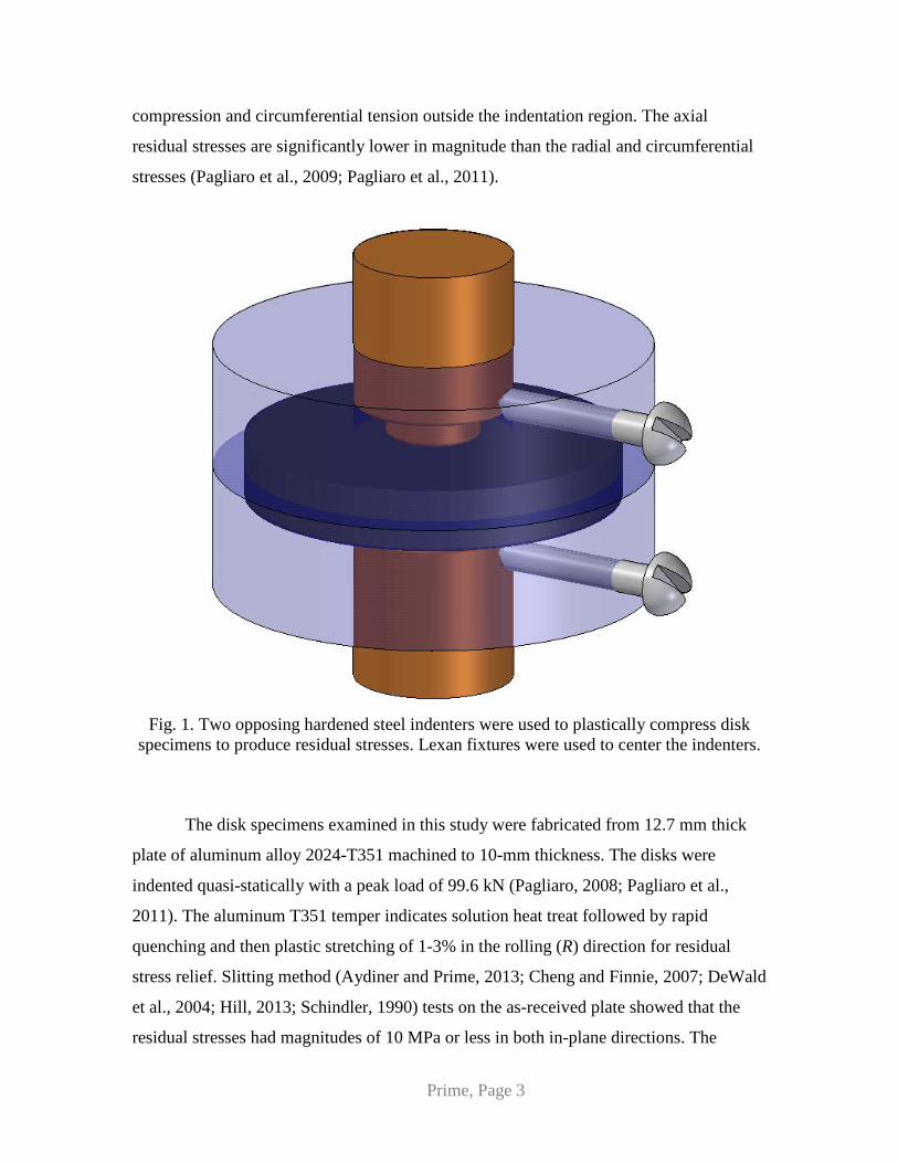
2. Specimen and Material Residual stress specimens had previously been designed and fabricated to provide
a unique, but axisymmetric, residual stress distribution for the original purpose of
validating new residual stress measurement methods. 10-mm thick, 60-mm diameter
metal disks were compressed plastically by opposing hardened steel indenters over a
central 13-mm diameter region of the specimen, see Fig. 1 (Mahmoudi et al., 2006;
Pagliaro, 2008; Pagliaro et al., 2009). Such indentation produces a residual stress
qualitatively similar to a shrink-fit ring and plug (Daymond et al., 2002), with biaxial
(radial and circumferential) compressive stress under the indenter and then radial
Prime, Page 3
compression and circumferential tension outside the indentation region. The axial
residual stresses are significantly lower in magnitude than the radial and circumferential
stresses (Pagliaro et al., 2009; Pagliaro et al., 2011).
Fig. 1. Two opposing hardened steel indenters were used to plastically compress disk
specimens to produce residual stresses. Lexan fixtures were used to center the indenters.
The disk specimens examined in this study were fabricated from 12.7 mm thick
plate of aluminum alloy 2024-T351 machined to 10-mm thickness. The disks were
indented quasi-statically with a peak load of 99.6 kN (Pagliaro, 2008; Pagliaro et al.,
2011). The aluminum T351 temper indicates solution heat treat followed by rapid
quenching and then plastic stretching of 1-3% in the rolling (R) direction for residual
stress relief. Slitting method (Aydiner and Prime, 2013; Cheng and Finnie, 2007; DeWald
et al., 2004; Hill, 2013; Schindler, 1990) tests on the as-received plate showed that the
residual stresses had magnitudes of 10 MPa or less in both in-plane directions. The
Prime, Page 4
typical grain dimensions in the plate were 30 µm in the through-thickness (TT) direction,
340 µm in the rolling direction, and 160 µm in the long transverse direction.
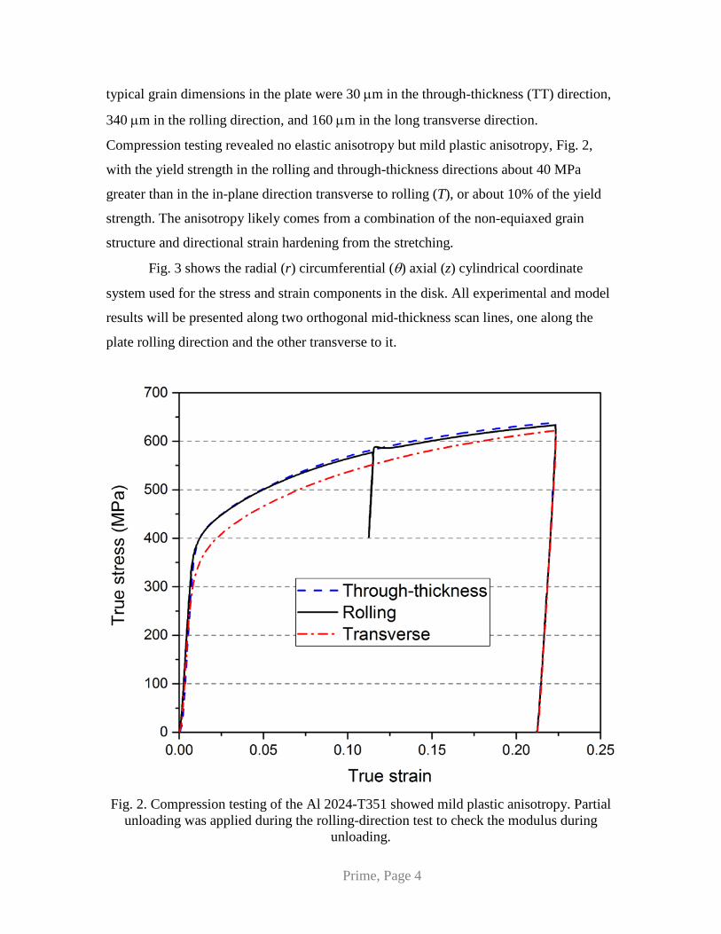
Compression testing revealed no elastic anisotropy but mild plastic anisotropy, Fig. 2,
with the yield strength in the rolling and through-thickness directions about 40 MPa
greater than in the in-plane direction transverse to rolling (T), or about 10% of the yield
strength. The anisotropy likely comes from a combination of the non-equiaxed grain
structure and directional strain hardening from the stretching.
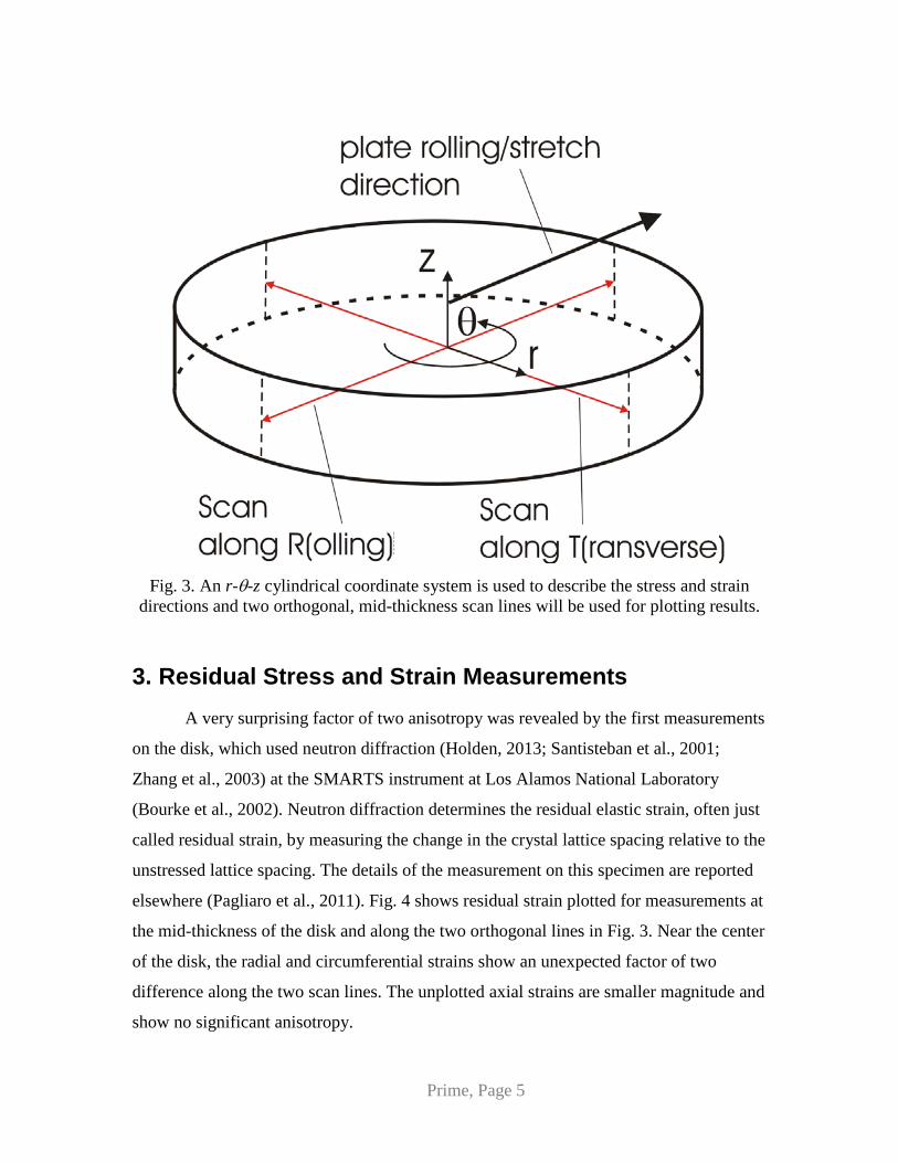
Fig. 3 shows the radial (r) circumferential (θ) axial (z) cylindrical coordinate
system used for the stress and strain components in the disk. All experimental and model
results will be presented along two orthogonal mid-thickness scan lines, one along the
plate rolling direction and the other transverse to it.
Fig. 2. Compression testing of the Al 2024-T351 showed mild plastic anisotropy. Partial
unloading was applied during the rolling-direction test to check the modulus during unloading.
Prime, Page 5
Fig. 3. An r-θ-z cylindrical coordinate system is used to describe the stress and strain
directions and two orthogonal, mid-thickness scan lines will be used for plotting results.
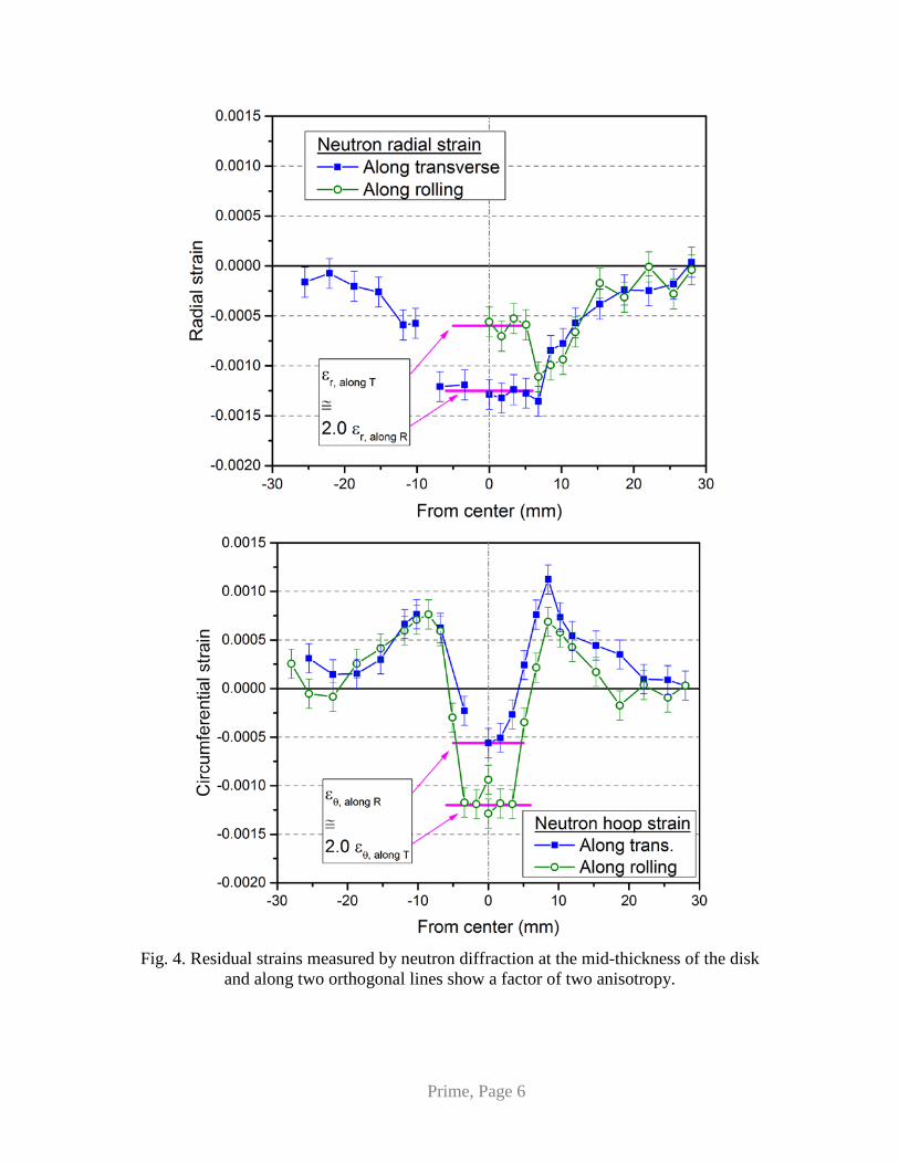
3. Residual Stress and Strain Measurements A very surprising factor of two anisotropy was revealed by the first measurements
on the disk, which used neutron diffraction (Holden, 2013; Santisteban et al., 2001;
Zhang et al., 2003) at the SMARTS instrument at Los Alamos National Laboratory
(Bourke et al., 2002). Neutron diffraction determines the residual elastic strain, often just
called residual strain, by measuring the change in the crystal lattice spacing relative to the
unstressed lattice spacing. The details of the measurement on this specimen are reported
elsewhere (Pagliaro et al., 2011). Fig. 4 shows residual strain plotted for measurements at
the mid-thickness of the disk and along the two orthogonal lines in Fig. 3. Near the center
of the disk, the radial and circumferential strains show an unexpected factor of two
difference along the two scan lines. The unplotted axial strains are smaller magnitude and
show no significant anisotropy.
Prime, Page 6
Fig. 4. Residual strains measured by neutron diffraction at the mid-thickness of the disk
and along two orthogonal lines show a factor of two anisotropy.
Prime, Page 7
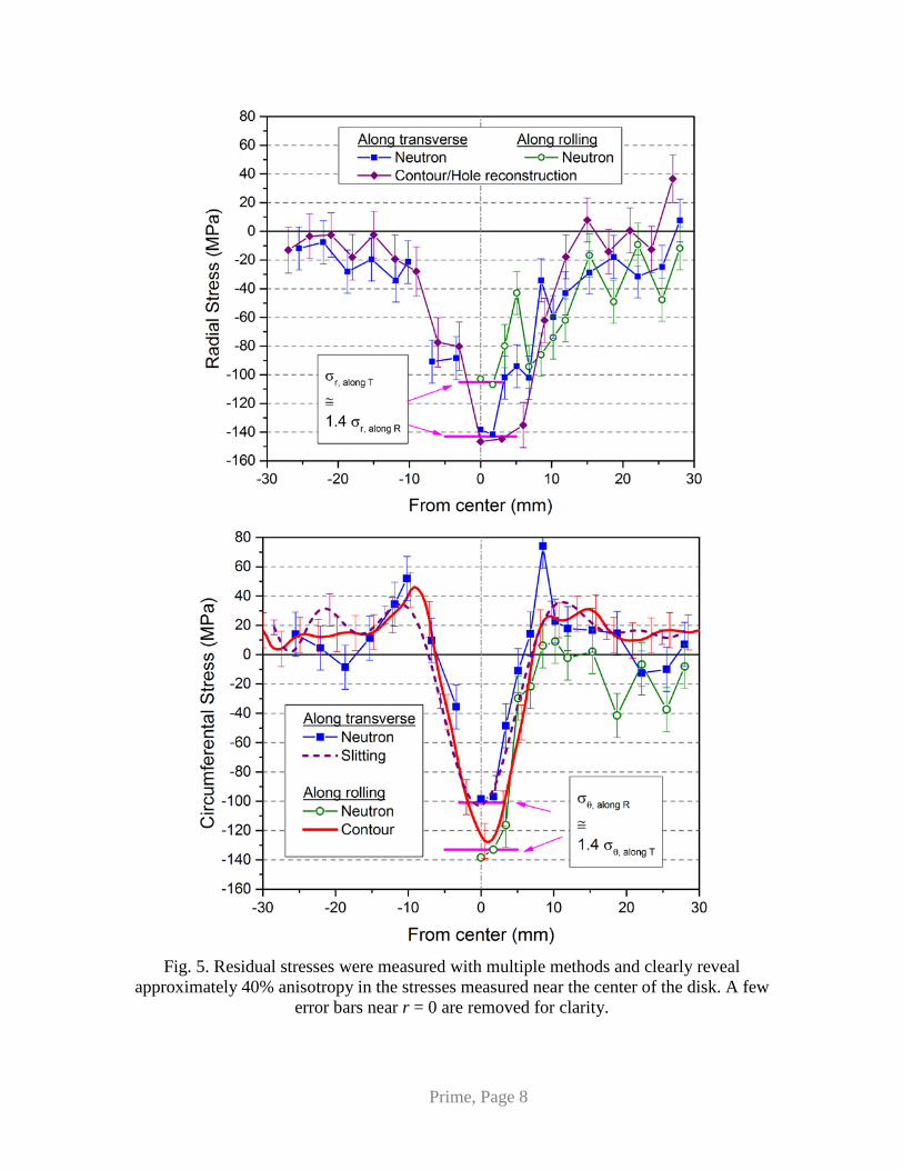
Examining residual stresses instead of strains showed anisotropy of about 40%,
and multiple measurement techniques on identically prepared specimens validated the
result. The elastic strains measured by neutron diffraction were used to calculate residual
stresses using Hooke’s law for isotropic elasticity (Pagliaro et al., 2011). The slitting
method (Cheng and Finnie, 2007; Hill, 2013; Lee and Hill, 2007) was used to measure
the thickness-averaged circumferential stress on a plane along the rolling direction
(Pagliaro, 2008). A cross-sectional map of residual circumferential stress was measured
on a plane along the transverse direction using the contour method (Hill and Olson, 2014;
Hosseinzadeh and Bouchard, 2013; Kartal et al., 2016; Prime and DeWald, 2013; Sarafan
et al., 2016; Withers et al., 2008; Xie et al., 2015; Zhang et al., 2003; Zhang et al., 2015),
and the details for this specimen have been reported previously (Pagliaro et al., 2011).
After the contour measurements, the radial stresses were measured on the exposed
surface using x-ray diffraction and hole drilling and superposition was used to reconstruct
the original stresses prior to the contour cut (Hosseinzadeh and Bouchard, 2013; Olson
and Hill, 2015; Pagliaro et al., 2011). All the measurements agree within uncertainty and
show the factor of 1.4 anisotropy in residual stress near the center of the disk.
Prime, Page 8
Fig. 5. Residual stresses were measured with multiple methods and clearly reveal
approximately 40% anisotropy in the stresses measured near the center of the disk. A few error bars near r = 0 are removed for clarity.
Prime, Page 9
The residual stresses also show another feature that might not be expected
intuitively. Both plots in Fig. 5 show that the peak stress magnitudes occur in the weaker
direction transverse to rolling: the radial stress along the transverse scan line and the
circumferential stress along the rolling direction scan line, both of which stresses act
along the transverse direction.
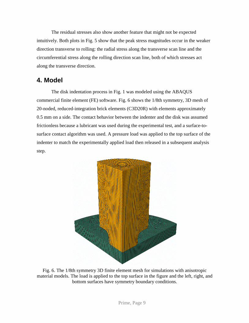
4. Model The disk indentation process in Fig. 1 was modeled using the ABAQUS
commercial finite element (FE) software. Fig. 6 shows the 1/8th symmetry, 3D mesh of
20-noded, reduced-integration brick elements (C3D20R) with elements approximately
0.5 mm on a side. The contact behavior between the indenter and the disk was assumed
frictionless because a lubricant was used during the experimental test, and a surface-to-
surface contact algorithm was used. A pressure load was applied to the top surface of the
indenter to match the experimentally applied load then released in a subsequent analysis
step.
Fig. 6. The 1/8th symmetry 3D finite element mesh for simulations with anisotropic
material models. The load is applied to the top surface in the figure and the left, right, and bottom surfaces have symmetry boundary conditions.

Prime, Page 10
The material model used here only included the physical phenomena needed to
model this particular test with sufficient fidelity. For similar disks of 316L stainless steel,
modeling the Bauschinger effect during unloading was necessary for an accurate residual
stress prediction (Pagliaro et al., 2009), but a computational study indicated that the Al
2024 disks did not reverse yield during unloading (Prime, 2013) so a simple isotropic
hardening model was sufficient. Similarly, modelling the pressure dependence of the
flow stress for 2024 Al (Bai and Wierzbicki, 2008) was found to have minimal effect on
the predicted residual stresses (Prime, 2013) and was ignored.
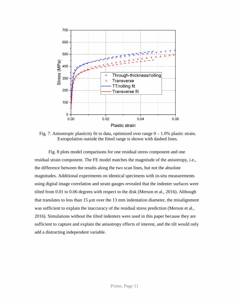
Plastic anisotropy was the important phenomenon and was modeled using Hill’s
potential function (Hill, 1948) in ABAQUS. Because the conversion of uniaxial stress-
strain curves to effective-stress – effective-strain curves depends on the anisotropy ratios,
an iterative process was used to fit the ratios to the data (Prime, 2013). Fig. 2 shows a
non-constant ratio between the stress-strain curves, so the anisotropy could not be fit
perfectly over the entire range. Simulations showed that the material in the disk away
from the stress concentration at the corner of the indenters did not exceed 1.5% plastic
strain and was lower in the regions of most interest. Therefore, Fig. 7 shows that the fit
was optimized for the range of strains up to 1%. This fit was applied in ABAQUS using
the *POTENTIAL function to define the anisotropy and a tabular description of the
stress-strain curve.
Prime, Page 11
Fig. 7. Anisotropic plasticity fit to data, optimized over range 0 – 1.0% plastic strain.
Extrapolation outside the fitted range is shown with dashed lines.
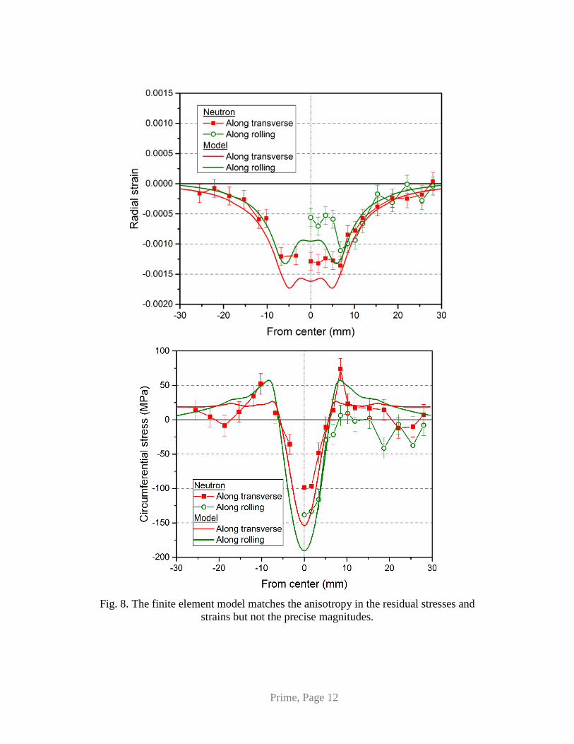
Fig. 8 plots model comparisons for one residual stress component and one
residual strain component. The FE model matches the magnitude of the anisotropy, i.e.,
the difference between the results along the two scan lines, but not the absolute
magnitudes. Additional experiments on identical specimens with in-situ measurements
using digital image correlation and strain gauges revealed that the indenter surfaces were
tilted from 0.01 to 0.06 degrees with respect to the disk (Merson et al., 2016). Although
that translates to less than 15 µm over the 13 mm indentation diameter, the misalignment
was sufficient to explain the inaccuracy of the residual stress prediction (Merson et al.,
2016). Simulations without the tilted indenters were used in this paper because they are
sufficient to capture and explain the anisotropy effects of interest, and the tilt would only
add a distracting independent variable.
Prime, Page 12
Fig. 8. The finite element model matches the anisotropy in the residual stresses and
strains but not the precise magnitudes.

Prime, Page 13
5. Results and Discussion
5.1. Amplified Stress Anisotropy and Higher Stress Direction
Fig. 9 shows the deformed FE model at peak load with the indenter removed from
the figure for clarity. The results of the 1/8 symmetry model of Fig. 6 were mirrored
vertically to make a ¼ symmetry plot. Looking at the shape, the most obvious
deformations are in the axial loading direction and peak at about 65 µm under the
indenter. The figure is colored by the radial displacements, which peak at only 36 µm.
Not surprisingly, the aluminum under the indenter preferentially bulges outward in the
weaker direction transverse to the rolling direction. The circumferential displacements
are much smaller because of the near-axisymmetric conditions, peaking at under 6 µm,
and provide no special insight.
Fig. 9. ¼ symmetry plot of disk shown at peak load with deformations exaggerated by a
factor of 20. Coloring by radial displacement shows that the aluminum under the indenter bulges out preferentially in the weaker directions transverse to rolling.
Explaining features in the residual stresses distributions requires looking at details
of the loading history of the aluminum. Fig. 10 plots stress vs. plastic strain curves
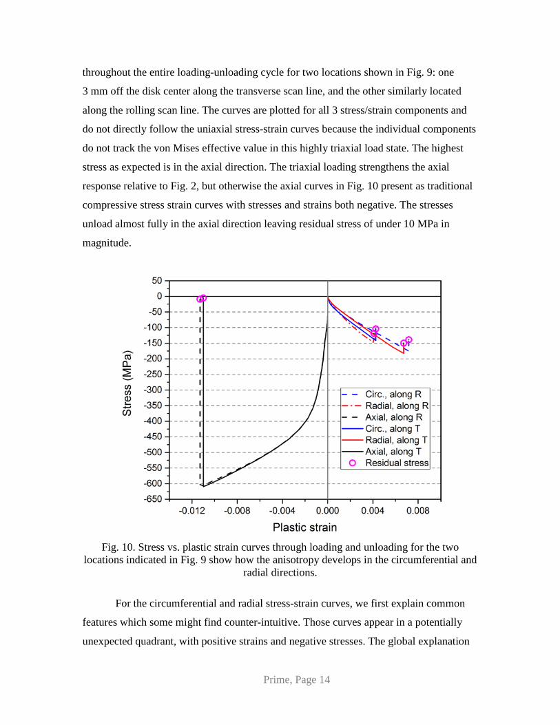
Prime, Page 14
throughout the entire loading-unloading cycle for two locations shown in Fig. 9: one
3 mm off the disk center along the transverse scan line, and the other similarly located
along the rolling scan line. The curves are plotted for all 3 stress/strain components and
do not directly follow the uniaxial stress-strain curves because the individual components
do not track the von Mises effective value in this highly triaxial load state. The highest
stress as expected is in the axial direction. The triaxial loading strengthens the axial
response relative to Fig. 2, but otherwise the axial curves in Fig. 10 present as traditional
compressive stress strain curves with stresses and strains both negative. The stresses
unload almost fully in the axial direction leaving residual stress of under 10 MPa in
magnitude.
Fig. 10. Stress vs. plastic strain curves through loading and unloading for the two
locations indicated in Fig. 9 show how the anisotropy develops in the circumferential and radial directions.
For the circumferential and radial stress-strain curves, we first explain common
features which some might find counter-intuitive. Those curves appear in a potentially
unexpected quadrant, with positive strains and negative stresses. The global explanation
Prime, Page 15
is that the volume-conserving expansion (plastic equivalent of the elastic Poisson effect)
caused by the axial compression is greater than the compressive strains caused by the
radial or circumferential compressive stress. More detail explanations will shed further
light. The positive radial strains occur because the aluminum compressed under the
indenter bulges outward. If we conceptually separate the aluminum under the indenter
from an outer ring of aluminum, the negative radial stress occurs because the outward-
bulging aluminum under the indenter is constrained by the outer ring. Ignoring anisotropy
for the moment, the constraint applied by the outer ring acts like an external pressure and
causes a nearly biaxial (circumferential-radial) compressive state in the aluminum under
the indenter. Circumferential strain, ignoring a smaller non-axisymmetric term, is given
by εθ = u/r, where u is the radial displacement and r is the radial coordinate. The formula
u/r represents the expansion of a circumferential path and is clearly positive for the
outward-bulging aluminum.
The development of anisotropy and of the higher stress direction shows up in the
circumferential and radial curves. At both locations the plastic strains peak higher in the
weaker direction, which is the circumferential direction for the point along R and the
radial direction for the location along T. Less intuitively, the plastic strain keeps
increasing in the weaker direction even after the stress in the weaker direction exceeds
the stress in the stronger direction. The preferential deformation continues in spite of the
higher resisting stress because the incremental stress increase, dσ/dε, also called the
tangent modulus, is lower in the weaker direction. Such a smaller slope at higher stress
levels in the weaker direction can be seen qualitatively in Fig. 7 and follows from the
concave-down curves.
From the peak stress state, both locations elastic unload about the same amount
leaving residual stresses higher in the weaker direction. The circumferential/radial stress
difference at peak load of about 35 MPa is retained after unloading.
5.2. Further Amplification of Strain Anisotropy
Hookean elasticity can explain why the strain anisotropy (×2) is so much greater
than the stress anisotropy (×1.4). For simplicity, we consider a point in the center of the
Prime, Page 16
disk where the rolling and transverse stresses along the two scan lines coincide. Ignoring
the axial stresses, which are small, the elastic strains can be calculated from the stresses
as
( )
( )rollingtransversetransversee
transverserollingrollinge
E
E
νσσε
νσσε
−=
−=
1
1
,
,. (1)
Where the subscript “e” refers to elastic. The anisotropy ratio in stress is defined as
rolling
transverseRσσ
σ = , (2)
where Rσ > 1 here. The anisotropy ratio in strain is defined similarly and evaluated using
Eqs. (1) and (2):
σ
σε ν
νεε
RRR
rollinge
transversee
−−
==1,
, . (3)
Examining Eq. (3) shows that the increased amplification in strain as compared to
stress comes from the Poisson contraction. For a Poisson’s ratio of 0, there is no
amplification (Rε = Rσ). On the other hand, for Rσ = 1/ν, Rε would be singular because
the Poisson contraction from the transverse stress precisely counteracts the strain caused
by the rolling stress, see Eq. (1).
Based on the empirical observation that the strain anisotropy was approximately
the square of the stress anisotropy, 2.0 ≈ 1.42, we expanded Eq. (3) in a Taylor expansion
around Rσ = 1:
( ) ( )( )
( ) ( )322 11
111
111 −+−
−
++−
−+
−= σσσεννν
νν RorderRRR
. (4)
Ignoring the higher order terms and substituting ν = 1/3 for aluminum gives 2σε RR ≈ , (5)
which confirms the empirical observation. However, Eq. (3) should be used in the general
case.
5.3. Broader Implications
The magnitude of stress anisotropy in the indented disk was largely determined by
the peak load. The model showed that the anisotropy increased throughout the loading,

Prime, Page 17
and further model calculations showed that the stress anisotropy would continue to
increase if the load were increased.
How prevalent might such anisotropy amplification be? In the indented aluminum
disk, the in-plane loading was nominally biaxial (axisymmetric in this case), which led to
the expectation of isotropic in-plane residual stresses and the surprising residual
stress/strain anisotropy. However, not all biaxial loading would be expected to show the
amplified residual stress anisotropy. Uniform plastic deformation throughout a part can
be used to reduce residual stresses by equalizing the stresses prior to unloading, as is
commonly used for stress relief in aluminum plate (Davis, 2009; Prime and Hill, 2002).
Biaxial stretching in an anisotropic plate would produce different stresses in the two
directions at peak load, but with sufficient stretching the stresses in each direction would
be nearly uniform over the plate cross-section and would relax to zero residual stress on
unloading. In the aluminum disk, the indentation was limited to the central region of the
disk, which provided the non-uniform plasticity that led to larger residual stresses. In
contrast to stretching, larger aluminum forgings are stress relieved using multiple cold
compressions applied over only localized regions (Prime et al., 2003; Robinson et al.,
2010; Tanner and Robinson, 2000, 2003), which would make the process susceptible to
the amplified anisotropy. Other processes that induce local biaxial stresses might be
susceptible to amplified anisotropy, such as rolling, forming, extrusion, stamping,
swaging, and more.
6. Conclusions Axisymmetric indentation of a geometrically axisymmetric aluminum disk
resulted in residual stress anisotropy of 40% and residual strain anisotropy of 100%, a
large amplification compared to the 10% plastic anisotropy of the aluminum. Distinct
causes explain the observed anisotropies. The high residual stress anisotropy relative to
the mild plastic anisotropy arises from the deformation constraint inherent in the
particular fabrication process. The high ratio of anisotropy in residual strain to that in
residual stress is independent of the fabrication process and is instead explained by
considering Hookean elasticity. For Poisson’s ratio of 1/3, the relationship simplifies to
the residual strain anisotropy equaling the square of the residual stress anisotropy.
Prime, Page 18
The peak residual stress occurred in the weaker material direction, which was
caused by preferential deformation in the direction with lower incremental stress
increase, dσ/dε, even when the stress magnitude was higher.
It has been previously demonstrated only a few times in the literature that
modeling plastic anisotropy is important to accurately predict residual stresses or related
phenomena when the plastic anisotropy is rather large (Alexandrov and Hwang, 2009;
Ball, 1995; He et al., 2003; Lee et al., 2012; Moverare and Odén, 2002; Thuillier et al.,
2002). This work indicates that even mild plastic anisotropy can have a large effect and
might have to be modeled to accurately predict residual stresses and strains.
7. Acknowledgement Los Alamos National Laboratory, an affirmative action/equal opportunity
employer, is operated by the Los Alamos National Security, LLC for the National
Nuclear Security Administration of the U.S. Department of Energy under contract DE-
AC52-06NA25396. By approving this article, the publisher recognizes that the U.S.
Government retains nonexclusive, royalty-free license to publish or reproduce the
published form of this contribution, or to allow others to do so, for U.S. Government
purposes. Los Alamos National Laboratory strongly supports academic freedom and a
researcher's right to publish; as an institution, however, the Laboratory does not endorse
the viewpoint of a publication or guarantee its technical correctness.
8. References Alexandrov, S., Hwang, Y.-M., 2009. The bending moment and springback in pure bending of anisotropic sheets. International Journal of Solids and Structures 46, 4361-4368. Aydiner, C.C., Prime, M.B., 2013. Three-Dimensional Constraint Effects on the Slitting Method for Measuring Residual Stress. Journal of Engineering Materials and Technology 135, 031006-031001. Bai, Y., Wierzbicki, T., 2008. A new model of metal plasticity and fracture with pressure and Lode dependence. International Journal of Plasticity 24, 1071-1096. Ball, D.L., 1995. Elastic-Plastic Stress Analysis of Cold Expanded Fastener Holes. Fatigue & Fracture of Engineering Materials & Structures 18, 47-63. Bourke, M.A.M., Dunand, D.C., Ustundag, E., 2002. SMARTS-A spectrometer for strain measurement in engineering materials. Applied Physics A: Materials Science & Processing 74, 1707-1709.
Prime, Page 19
Cheng, W., Finnie, I., 2007. Residual Stress Measurement and the Slitting Method. Springer Science+Business Media, LLC, New York, NY, USA. Davis, J.R., 2009. ASM Handbook Volume 2. Properties and selection: nonferrous alloys and special-purpose materials. ASM International. Daymond, M.R., Johnson, M.W., Sivia, D.S., 2002. Analysis of neutron diffraction strain measurement data from a round robin sample. The Journal of Strain Analysis for Engineering Design 37, 73-85. DeWald, A.T., Rankin, J.E., Hill, M.R., Schaffers, K.I., 2004. An improved cutting plan for removing laser amplifier slabs from Yb:S-FAP single crystals using residual stress measurement and finite element modeling. Journal of Crystal Growth 265, 627-641. Gonzalez, D., Simonovski, I., Withers, P.J., Quinta da Fonseca, J., 2014. Modelling the effect of elastic and plastic anisotropies on stresses at grain boundaries. International Journal of Plasticity 61, 49-63. He, S., Van Bael, A., Li, S.Y., Van Houtte, P., Mei, F., Sarban, A., 2003. Residual stress determination in cold drawn steel wire by FEM simulation and X-ray diffraction. Materials Science and Engineering: A 346, 101-107. Hill, M.R., 2013. The Slitting Method, in: Schajer, G.S. (Ed.), Practical Residual Stress Measurement Methods. John Wiley & Sons, Ltd, pp. 89-108. Hill, M.R., Olson, M.D., 2014. Repeatability of the Contour Method for Residual Stress Measurement. Experimental Mechanics 54, 1269-1277. Hill, R., 1948. A Theory of the Yielding and Plastic Flow of Anisotropic Metals. Proceedings of the Royal Society of London. Series A. Mathematical and Physical Sciences 193, 281-297. Holden, T.M., 2013. Neutron Diffraction, in: Schajer, G.S. (Ed.), Practical Residual Stress Measurement Methods. John Wiley & Sons, Ltd, pp. 195-223. Hosseinzadeh, F., Bouchard, P., 2013. Mapping Multiple Components of the Residual Stress Tensor in a Large P91 Steel Pipe Girth Weld Using a Single Contour Cut. Experimental Mechanics 53, 171-181. Johansson, J., Odén, M., Zeng, X.H., 1999. Evolution of the residual stress state in a duplex stainless steel during loading. Acta Materialia 47, 2669-2684. Kartal, M.E., Kang, Y.H., Korsunsky, A.M., Cocks, A.C.F., Bouchard, J.P., 2016. The influence of welding procedure and plate geometry on residual stresses in thick components. International Journal of Solids and Structures 80, 420-429. Knezevic, M., Beyerlein, I.J., Brown, D.W., Sisneros, T.A., Tomé, C.N., 2013. A polycrystal plasticity model for predicting mechanical response and texture evolution during strain-path changes: Application to beryllium. International Journal of Plasticity 49, 185-198. Lee, J.-W., Lee, M.-G., Barlat, F., 2012. Finite element modeling using homogeneous anisotropic hardening and application to spring-back prediction. International Journal of Plasticity 29, 13-41. Lee, M.J., Hill, M.R., 2007. Intralaboratory repeatability of residual stress determined by the slitting method. Experimental Mechanics 47, 745-752. Mahmoudi, A.H., Stefanescu, D., Hossain, S., Truman, C.E., Smith, D.J., Withers, P.J., 2006. Measurement and prediction of the residual stress field generated by side-punching. Journal of Engineering Materials and Technology 128, 451-459.
Prime, Page 20
Merson, J.S., Prime, M.B., Lovato, M.L., Liu, C., 2016. In-Situ DIC and Strain Gauges to Isolate the Deficiencies in a Model for Indentation Including Anisotropic Plasticity, in: Bossuyt, S., Schajer, G., Carpinteri, A. (Eds.), Residual Stress, Thermomechanics & Infrared Imaging, Hybrid Techniques and Inverse Problems, Volume 9. Springer International Publishing, pp. 183-197. Moverare, J.J., Odén, M., 2002. Influence of elastic and plastic anisotropy on the flow behavior in a duplex stainless steel. Metallurgical and Materials Transactions A 33, 57-71. Mróz, Z., 1967. On the description of anisotropic workhardening. Journal of the Mechanics and Physics of Solids 15, 163-175. Olson, M.D., Hill, M.R., 2015. A New Mechanical Method for Biaxial Residual Stress Mapping. Experimental Mechanics 55, 1139-1150. Pagliaro, P., 2008. Mapping Multiple Residual Stress Components Using the Contour Method and Superposition. Universitá degli Studi di Palermo, Palermo. Pagliaro, P., Prime, M.B., Clausen, B., Lovato, M.L., Zuccarello, B., 2009. Known Residual Stress Specimens Using Opposed Indentation. Journal of Engineering Materials and Technology 131, 031002. Pagliaro, P., Prime, M.B., Robinson, J.S., Clausen, B., Swenson, H., Steinzig, M., Zuccarello, B., 2011. Measuring Inaccessible Residual Stresses Using Multiple Methods and Superposition. Experimental Mechanics 51, 1123-1134. Prime, M.B., 2013. Anisotropic and Pressure-Dependent Plasticity Modeling for Residual Stress Prediction, in: Ventura, C.E., Crone, W.C., Furlong, C. (Eds.), Experimental and Applied Mechanics, Volume 4, Conference Proceedings of the Society for Experimental Mechanics Series. Springer New York, pp. 415-427. Prime, M.B., DeWald, A.T., 2013. The Contour Method, in: Schajer, G.S. (Ed.), Practical Residual Stress Measurement Methods. John Wiley & Sons, Ltd., Chichester,WestSussex, UK. Prime, M.B., Hill, M.R., 2002. Residual stress, stress relief, and inhomogeneity in aluminum plate. Scripta Materialia 46, 77-82. Prime, M.B., Newborn, M.A., Balog, J.A., 2003. Quenching and cold-work residual stresses in aluminum hand forgings: contour method measurement and FEM prediction. Materials Science Forum 426-432, 435-440. Robinson, J.S., Hossain, S., Truman, C.E., Paradowska, A.M., Hughes, D.J., Wimpory, R.C., Fox, M.E., 2010. Residual stress in 7449 aluminium alloy forgings. Materials Science and Engineering: A 527, 2603-2612. Santisteban, J.R., Edwards, L., Steuwer, A., Withers, P.J., 2001. Time-of-flight neutron transmission diffraction. Journal of Applied Crystallography 34, 289-297. Sarafan, S., Lévesque, J.B., Wanjara, P., Gholipour, J., Champliaud, H., 2016. Distortion and residual stresses in electron beam-welded hydroelectric turbine materials. Science and Technology of Welding and Joining 21, 473-478. Schindler, H.J., 1990. Determination of residual stress distributions from measured stress intensity factors. International Journal of Fracture 74, R23-R30. Tanner, D.A., Robinson, J.S., 2000. Residual stress prediction and determination in 7010 aluminum alloy forgings. Experimental Mechanics 40, 75-82.

Prime, Page 21
Tanner, D.A., Robinson, J.S., 2003. Modelling stress reduction techniques of cold compression and stretching in wrought aluminium alloy products. Finite Elements in Analysis and Design 39, 369-386. Thuillier, S., Manach, P.Y., Menezes, L.F., Oliveira, M.C., 2002. Experimental and numerical study of reverse re-drawing of anisotropic sheet metals. Journal of Materials Processing Technology 125–126, 764-771. Withers, P.J., Turski, M., Edwards, L., Bouchard, P.J., Buttle, D.J., 2008. Recent advances in residual stress measurement. The International Journal of Pressure Vessels and Piping 85, 118-127. Wronski, S., Wrobel, M., Baczmanski, A., Wierzbanowski, K., 2013. Effects of cross-rolling on residual stress, texture and plastic anisotropy in f.c.c. and b.c.c. metals. Materials Characterization 77, 116-126. Xie, P., Zhao, H., Wu, B., Gong, S., 2015. Evaluation of Residual Stresses Relaxation by Post Weld Heat Treatment Using Contour Method and X-ray Diffraction Method. Experimental Mechanics 55, 1329-1337. Zhang, Y., Ganguly, S., Stelmukh, V., Fitzpatrick, M.E., Edwards, L., 2003. Validation of the Contour Method of Residual Stress Measurement in a MIG 2024 Weld by Neutron and Synchrotron X-ray Diffraction. Journal of Neutron Research 11, 181-185. Zhang, Z., Yang, Y., Li, L., Chen, B., Tian, H., 2015. Assessment of residual stress of 7050-T7452 aluminum alloy forging using the contour method. Materials Science and Engineering: A 644, 61-68. Zolotorevsky, N.Y., Krivonosova, N.Y., 1996. Effect of ferrite crystals' plastic anisotropy on residual stresses in cold-drawn steel wire. Materials Science and Engineering: A 205, 239-246.