Embed Size (px)
Citation preview

Residential Technical Manual
750 Alpha Drive • Cleveland, Ohio • 44143 440.461.2000 • Fax 440.442.9008 [email protected] • www.jetincorp.com


TABLE OF CONTENTS
About Jet………………...................................... 1Residential Brochure…………………………… 31500 BAT Media Plant Owner’s Manual……… 7Home Plant Owner’s Protection Program……… 14NSF Product and Service Listing Information…. 16Plant Drawings…………………………………. 17 500 GPD……………………………………. 18 750 GPD……………………………………. 19 1,000 GPD………………………………….. 20 1,250 GPD………………………………….. 21 1,500 GPD………………………………….. 22Plant Inspection………………………………… 23Plant Inspection Service Policy………………… 25Aerator Silencer………………………………... 27UV 3G Disinfection Information………………. 28Truck Talk……………………………………… 33BioJet-7 Maintenance Instructions……………... 35
750 Alpha Drive Cleveland, Ohio 44143
800.321.6960 www.jetincorp.com


About Jet
Our Mission Statement: To be the #1 provider of advanced onsite wastewater treatment systems throughout the world, while offering a superior product and outstanding customer service.
Founded in 1955, David S. MacLaren acted on an innovative idea. While working closely with his father, Albert MacLaren, they designed and patented an aerator for family homes that would more effectively treat and dispose of residential wastewater, changing the technology in the wastewater treatment business forever!A close look at our competitors will highlight how much of an innovator we are as most of the competing concrete tanks are modeled after our design, but they can’t copy another Jet innovation, our patented BAT® media. This makes Jet the true pioneer and a leader in onsite wastewater treatment both in residential and commercial settings.
Offering a high level of customer service and cutting edge products in an ever changing industry, Jet is the LEADER in wastewater technology. Jet’s representatives design, install and service the best products in the industry!
The ProductsJet concentrates on water pollution control, producing equipment and components for package wastewater treatment plants. Starting with a residential plant, the company refi ned and worked with this product so that today it is the most accepted, largest selling home plant in the country. Next, Jet added a complete line of commercial plants designed to serve factories, apartments, hospitals, service stations, trailer parks, and dozens of similar installations located beyond city sewer lines. To support its commercial plants Jet offers a complete line of optional equipment and accessories.A unique feature of Jet’s Commercial Plant is the patented Jet Air-Seal Diffuser® . The fi rst truly non-clog diffuser in the fi eld, it has been acclaimed by health authorities and engineers.Jet’s product lines also include JET-CHLOR® Wastewater Disinfectant Systems, CHLOR-AWAY® Dechlorination Systems, Jet Tablet Feeders, BIO JET-7®, a natural, organic wastewater additive, Lift Stations, Liquid Level Alarms, Controllers and a broad range of other wastewater treatment products and equipment.Field-proven in thousands of installations, Jet plants have successfully undergone hundreds of testing programs and performance evaluations at the local, state, and national levels.
The DistributorJet has a strong network of distributors licensed to sell, install, and service Jet Treatment Plants. Jet works with these local distributors, guiding them with training and follow-up in engineering, production, sales and offi ce procedures. The company arranges frequent training seminars at its factory and sends factory specialists to aid the distributor in his territory. Jet prides itself on this program of close cooperation with its distributors, and credits this with being one of the major elements contributing to the distributors’ success.As Jet’s management puts it: “Jet products plus Jet training plus Jet Distributors make an unbeatable pollution control team.”
1


OWNER’S MANUAL
1500 Series BAT® Media Plants
7
OWNER’S MANUAL
Jet Inc. • 750 Alpha Dr. • Cleveland, OH 44143 USA • 440.461.2000JET, JET AERATION, BAT, AIR-SEAL, JET CHLOR, CHLOR-AWAY, and BIO JET-7 are registered trademarks of JET, INC.
Fax 440.442.9008 • [email protected] • www.jetincorp.com 0304 JET, INC © MMIV
2
PLANT MODELS
Jet Media Plants are available in six sizes – 500, 600, 750, 1000, 1250 & 1500 gpd (“gpd” means “gallons per day” and refers to the way wastewater treatment plants are rated). Plants in the J-1500 Series have been tested and meet NSF Standard 40 criteria for a Class I NSF Listing. Most 500 through 750 gpd plants serve single family dwellings. Larger plants normally serve other buildings.
500, 600 & 750 GPD PLANTS
All information in this manual is directed to owners of plantsin these sizes. The exception is the section directed to ownersof 1000 through 1500 gpd plants.
BAT® PROCESS
Your plant uses Jet’s exclusive wastewater treatment process called Biologically Accelerated Treatment, or BAT® for short.
In this process, millions of microorganisms attach themselves to the media. The Jet Aerator supplies the oxygen utilized by the microorganisms to convert the waste to colorless, odorless liquids and gases. This process provides an extraordinarily high degree of treatment.
CONTENTS
PLANT MODELS................................................................................ 2500, 600 & 750 GPD PLANTS ........................................................... 2BAT® PROCESS ................................................................................. 2JET TANK............................................................................................ 3500 THROUGH 1500 GPD PLANTS.................................................. 3JET AERATOR .................................................................................... 3CONTROL PANEL.............................................................................. 4JET-CHLOR® CHLORINATION ....................................................... 4CHLOR-AWAY® DECHLORINATION ............................................ 4BIO JET-7®.......................................................................................... 5INSPECTION & SERVICE.................................................................. 5 Local Distributor Limited Warranty & Service Policy Renew Your Inspection & Service Policy Service IntervalsDOS & DON’TS .................................................................................. 6 Avoid These Items Plant Landscaping Vacations & Intermittent UseWARRANTY........................................................................................ 7
1500 Series BAT® Media Plants
500 GPD PLANT
600 AND 750 GPD PLANT
BAT® MEDIA
SET B
BAT® MEDIA
SET A
FLOW LINE
FLOW LINE
8

OWNER’S MANUAL
Jet Inc. • 750 Alpha Dr. • Cleveland, OH 44143 USA • 440.461.2000JET, JET AERATION, BAT, AIR-SEAL, JET CHLOR, CHLOR-AWAY, and BIO JET-7 are registered trademarks of JET, INC.
Fax 440.442.9008 • [email protected] • www.jetincorp.com 0304 JET, INC © MMIV
3
JET TANK
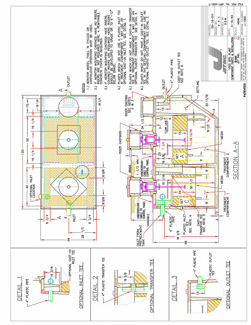
The tank has three compartments. Arrows on the diagram indicate the flow direction. The Pretreatment Compartment, on the left, receives wastewater and treats it physically and biologically. The Jet Aerator provides mixing and injects fresh air into the Treatment Compartment contents.
The wastewater flows through the plant, receiving treatment as it travels to the Settling Compartment. Here, fine particles settle and return to the Treatment Compartment, for further processing, leaving only a clear, odorless liquid for final discharge.
The aerator is the only mechanical component in your plant. It requires no owner maintenance.
Fresh, outside air is drawn into the Treatment Compartment by the aerator. Air travels down the mounting casting cover air vent through the aerator and into the tank, providing oxygen for the treatment process. Any foam is controlled by the foam restrictor.
Aerator operation is virtually silent. If the plant is located near an open window, you may detect the sound of air moving into the treatment tank.
For virtually silent operation, please ask your Jet Distributor to install an Aerator Silencer.
Jet has a Flood proof aerator. The Flood proof model is sealed to protect it from damage by water. It is not designed to operate under water. If a high water level occurs, the control panel circuit breaker will open, shutting off power to the aerator. The warning light will turn “on”. If this happens, press the circuit breaker reset button on the control panel to restart the aerator.
500 THROUGH 1500 GPD PLANTS
JET AERATOR
Pretreatment Compartment
Treatment Compartment
Media
Settling Compartment
Control Panel
Variable
Grade
Underground Cable to Control Panel
Control Panel Control Panel
Settling Compartment
Treatment Compartment 1
From Pretreatment Tank
Variable
Underground Cable to Control Panel
Grade
MediaMedia
Underground Cable to Control Panel
Treatment Compartment 2
9
OWNER’S MANUAL
Jet Inc. • 750 Alpha Dr. • Cleveland, OH 44143 USA • 440.461.2000JET, JET AERATION, BAT, AIR-SEAL, JET CHLOR, CHLOR-AWAY, and BIO JET-7 are registered trademarks of JET, INC.
Fax 440.442.9008 • [email protected] • www.jetincorp.com 0304 JET, INC © MMIV
4
CONTROL PANEL
The control panel should be mounted where it can be easily accessed and seen. A wiring diagram and instructions are inside the control panel cover. Energy requirements are 115 Volt, 60 Hz. Electrical work must be performed in accordance with the requirements of the National Electrical Codes and local codes.
If the red visual alert light glows and/or an audible alert buzzer sounds, the circuit breaker has opened to protect the aerator. To restart the aerator, press the circuit breaker reset button. If the breaker does not stay “set”, causing the light and/or buzzer to repeatedly operate, contact your Jet Distributor.
Also, your control panel has an audible alert buzzer. It sounds when the circuit breaker trips. Also, the red visual alert light goes “ON.” Both buzzer and alert light can be turned off by pressing the control panel circuit breaker reset button. Normally, this will restart the aerator.
If the buzzer and alert light come on repeatedly, turn the switch in the control panel to “OFF” and immediately call your Jet Distributor to service.
JET-CHLOR® CHLORINATION
Your plant may be equipped with a JET-CHLOR® Tablet Chlorinator. It is installed on the plant discharge line.
If you have a chlorinator, read the “Installation and Operation” manual. This gives instructions for easy operation and maintenance.
We strongly recommend you use only JET-CHLOR® Tablets. They are EPA approved while many others are not. See your local dealer to purchase JET-CHLOR® and to receive additional information.
CHLOR-AWAY® DECHLORINATION
If you have a chlorinator, your plant may be equipped with the Jet Dechlorinator. This is installed after the chlorinator on the discharge line.
We strongly recommend that you use only CHLOR-AWAY® Tablets in your dechlorinator. Our tablets are highly effective and cost efficient. See your local dealer to purchase CHLOR-AWAY® and to receive additional information.
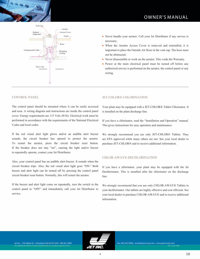
● Never handle your aerator. Call your Jet Distributor if any service is necessary.
● When the Aerator Access Cover is removed and reinstalled, it is important to place the Outside Air Hose in the vent cap. The hose must not be obstructed.
● Never disassemble or work on the aerator. This voids the Warranty.● Power at the main electrical panel must be turned off before any
authorized service is performed on the aerator, the control panel or any wiring.
Flow Line
Underground Cable
Padlock(Optional)
Vent Cap
AeratorAccess Cover
Grade
Riser
Mounting Casting
10

OWNER’S MANUAL
Jet Inc. • 750 Alpha Dr. • Cleveland, OH 44143 USA • 440.461.2000JET, JET AERATION, BAT, AIR-SEAL, JET CHLOR, CHLOR-AWAY, and BIO JET-7 are registered trademarks of JET, INC.
Fax 440.442.9008 • [email protected] • www.jetincorp.com 0304 JET, INC © MMIV
5
BIO JET-7®
● BIO JET-7® is a natural, organic, non-toxic liquid that gets new plants and plants that have just completed their 3-year service off to a running start. When used as directed, BIO JET-7® prevents grease traps from clogging and eliminates septic tank odors. It really works!
● If your neighbors have a smelly septic tank, suggest they get a bottle of BIO JET-7®. It is their first line of defense for dealing with their septic odor problems.
● Periodic application of BIO JET-7® and following the recommended plant maintenance will keep your plant running in top form.
INSPECTION & SERVICE
LOCAL DISTRIBUTORThe local Jet Distributor who installed your Jet Plant is trained, experienced and properly equipped to handle service and answer any questions. Your distributor’s name and phone number are posted on the cover of your control panel.
LIMITED WARRANTY & SERVICE POLICYYour Limited Warranty and Inspection/Service Policy are printed on a card accompanying this manual.
RENEW YOUR INSPECTION/SERVICE POLICYFor the first two years, your Jet Distributor provides free inspection and service. This Inspection/Service Policy includes repair, service and maintenance calls at no charge. After the first two years, renew your Inspection/Service Policy with your Jet Distributor.
SERVICE INTERVALS6-Month Service: This comprehensive service call includes collection and assessment of a post-treatment sample, inspection, servicing, cleaning, removal, reinstallation and testing of the aerator by a trained serviceman.
12-Month Service: This call provides all elements of the 6-Month Service as well as media cleaning.
3-Year Service: This service provides all steps in the 6- and 12-month service and tank pumping, if necessary. If you have not renewed your Inspection/Service Policy, you will be charged for the 30- and 36-month service calls. Tank pumping is not included under your Jet Distributor’s Inspection/Service Policy. It is charged to you by your tank pumper. If you have kept your service policy in force, there will be no charge for aerator service. Make sure you notify your Jet Distributor before you have your tank pumped. If the tank pumper is not familiar with Jet’s media and media has not been cleaned before pumping, severe damage to the media can occur. This is potentially very costly to repair.
PLANT SERVICE – 3 YEAR CYCLE
Service Months
6 12 18 24 30 36
6-Month � � � � � �
12-Month � � �
3-Year �
11
OWNER’S MANUAL
Jet Inc. • 750 Alpha Dr. • Cleveland, OH 44143 USA • 440.461.2000JET, JET AERATION, BAT, AIR-SEAL, JET CHLOR, CHLOR-AWAY, and BIO JET-7 are registered trademarks of JET, INC.
Fax 440.442.9008 • [email protected] • www.jetincorp.com 0304 JET, INC © MMIV
6
DOS & DON’TS
AVOID THESE ITEMSDo not put any of the following items in your plant or sewage system. They will cause serious damage to the plant biological process and equipment.
1. Plastic, sanitary napkins, scouring pads, condoms, mop strings, “disposable” diapers, towels, lint, rags, etc. These items should be disposed with household refuse. Wrap in paper if necessary.
2. Paints, thinners, chemicals, grease, solvents and sanitizes. Check with local health department for recycling facilities.
3. Water softener backwash. Route to drainage ditch, storm sewer or downspout drainage system.
4. Plumbing cleaners. Avoid using these products.
PLANT LANDSCAPINGMost owners plant grass over their Jet Plant. Many owners prefer planting a flower bed. Myrtle, pachysandra or shrubbery is also attractive. Do not position anything permanently over below-grade access covers. They must be accessible for service. (See drawings on page 2.) It is very important that the finished grade slope away from the plant. Also, grade must be at least 1” below the bottom of the manhole covers.
VACATIONS & INTERMITTENT USEIf your plant serves a vacation home or a building in which all occupants will be absent part of the time, the plant should be left running and cycled as it is during any absences. This will clean the Treatment Compartment during the absence and keep the plant in top operating condition.
12

OWNER’S MANUAL
Jet Inc. • 750 Alpha Dr. • Cleveland, OH 44143 USA • 440.461.2000JET, JET AERATION, BAT, AIR-SEAL, JET CHLOR, CHLOR-AWAY, and BIO JET-7 are registered trademarks of JET, INC.
Fax 440.442.9008 • [email protected] • www.jetincorp.com 0304 JET, INC © MMIV
7
AT T E N T I O N !A E R ATO R WA R R A N T Y I S V O I D I F A 7 A M P C I R C U I T B R E A K E R
A N D A J E T CO N T R O L PA N E L A R E N OT U S E D.
Jet Inc. warrants every new Jet aerator against defective materials and workmanship, under normal service, for 30 months commencing on the date of original installation if a complete warranty card is returned to Jet Inc. within 20 days from the date of installation or within 20 days after the original purchaser moves into the building or home serviced by the aerator or on the date of shipment form the factory if no warranty card is returned within the time period described above.
To make a claim under this warranty notify your Jet Distributor. All aerators covered under the warranty must be returned to the factory by a Jet Distributor. Jet Inc., at its option, may elect to repair or replace the aerator, or refund the purchase price of the aerator. Jet Inc. will provide the appropriate remedy within 60 days after confirming that the claim is covered by the warranty. Jet Inc. reserves the right to replace the aerator with an aerator of comparable quality and does not guarantee that it will match the original aerator. If any warranty repair is needed, it will be made at the factory. The owner shall assume all responsibility for freight charges to and from the factory. If there are parts missing from the
returned aerator, an additional charge will be made.
If there is any in-warranty media repair or replacement, this will be taken care of by the Jet Distributor at the installation, with no charge for labor or materials. Media damaged caused by owners or unauthorized persons is not covered in the warranty.
This warranty does not cover any Jet aerators damaged due (1) to disassembly by unauthorized persons, (2) improper installation, (3) misuse, (4) lightning, (5) external damage, (6) improper or altered wiring, (7) improper overload protection, (8) failure to follow the instructions in the Owner’s Manual (9) failure to maintain a service policy after the
free initial service policy expires. This warranty applies to all Jet 700 LL
Series Aerators made by and bearing the name Jet Inc. This warranty also does not cover any of the building, home wiring, plumbing, drainage or any other part of the disposal system.
JET INC. SHALL NOT BE RESPONSIBLE FOR ANY INCIDENTAL, CONSEQUENTIAL OR PUNITIVE DAMAGE CAUSED BY DEFECTIVE COMPONENTS OR MATERIALS OR FOR ANY LOSS INCURRED BECAUSE OF THE INTERRUPTION OF SERVICE, OR ANY OTHER SPECIAL CONSEQUENTIAL, OR INCIDENTAL DAMAGES OR EXPENSES ARISING FROM THE MANUFACTURE, SALE, USE OR MISUSE OF ANY JET PRODUCTS COVERED HEREUNDER. THIS WARRANTY IS IN LIEU OF ALL OTHER EXPRESS WARRANTIES. ANY WARRANTY IMPLIED BY LAW, INCLUDING IMPLIED WARRANTIES OF MERCHANTABILITY OR FITNESS FOR A PARTICULAR PURPOSE (IF APPLICABLE), AND IS IN EFFECT ONLY FOR THE WARRANTY PERIOD SPECIFIED ABOVE. (SOME STATES DO NOT ALLOW EXCLUSIONS OR LIMITATIONS OF INCIDENTAL OR CONSEQUENTIAL DAMAGES SO THE ABOVE MAY NOT APPLY TO YOU.) SOME STATES DO NOT ALLOW LIMITATIONS OF HOW LONG AN IMPLIED WARRANTY LASTS, SO THE ABOVE LIMITATIONS MAY NOT APPLY TO YOU.
Jet Inc. reserves the right to revise, change or modify the construction and design of any and all Jet products or any component part or parts thereof, without incurring any obligation to make such changes or modifications in present equipment. This warranty gives you specific legal rights, and you may also have other rights, which vary from state to state.
30 MONTH LIMITED WARRANTY
13

Home Plant Owner Protection Program
The owner of a JET Wastewater Treatment Plant is assured of continuous, economical service by Jet’s aerator warranty and exchange program and by a strong Jet Distributor program of warranty, back-up and service.
30-Month Limited WarrantyJet Inc. warrants every new JET Aerator control panel media assem-bly and any other material purchased from Jet against defective ma-terials and workmanship, under normal service, for 30 months com-mencing (i) upon date of original installation if a completed warranty card is returned to Jet Inc. within 20 days from the date of installation or within 20 days after the original purchaser moves into the resi-dence serviced by the aerator or (ii) upon the date of shipment from the factory if no warranty card is returned.To make a claim under this warranty you should notify your Jet Dis-tributor or notify Jet Inc. Customer Service Department, 750 Alpha Drive, Cleveland, Ohio 44143.Aerators and control panels must be removed and returned to the factory by a Jet Distributor. If any in-warranty repairs are needed, the aerator will be repaired at the factory with no charge for labor or materials. The purchaser shall assume all responsibility for freight charges to and from the factory. If there are missing parts, an addi-tional charge will be made.Media assemblies will be repaired/replaced by the Jet Distributor at the installation. If in-warranty repairs are needed, the media will be repaired/replaced with no charge for labor and materials.The warranty does not cover standard model aerators and control panels that have been damaged by water, or aerators that have been (i) damaged due to disassembly by unauthorized persons, improper installation, misuse, or lightning, (ii) subjected to external damage, (iii) damaged due to improper or altered wiring or overload protec-tion or (iv) damaged by failure to follow the suggestions outlined in the Owner’s Manual.
The warranty applies only to the JET Aerator and does not include any of the house wiring, plumbing, drainage, or any other part of the disposal system.JET INC. SHALL NOT BE HELD RESPONSIBLE FOR ANY DAMAGES CAUSED BY DEFECTIVE COMPONENTS OR MA-TERIALS, OR FOR LOSS INCURRED BECAUSE OF THE IN-TERRUPTION OF SERVICE, OR ANY OTHER SPECIAL, CON-SEQUENTIAL, OR INCIDENTAL DAMAGES OR EXPENSES ARISING FROM THE MANUFACTURE, SALE, USE OR MIS-USE OF THE AERATOR. THE WARRANTY IS IN LIEU OF ALL OTHER EXPRESS WARRANTIES. ANY WARRANTY IMPLIED BY THE LAW, INCLUDING IMPLIED WARRANTIES OF MER-CHANTABILITY OR FITNESS FOR A PARTICULAR PURPOSE (IF APPLICABLE), IS IN EFFECT ONLY FOR THE 30-MONTH WARRANTY PERIOD SPECIFIED ABOVE. (SOME STATES DO NOT ALLOW EXCLUSIONS OR LIMITATIONS OF INCIDEN-TAL OR CONSEQUENTIAL DAMAGES OR ALLOW LIMITA-TIONS OF HOW LONG AN IMPLIED WARRANTY LASTS, SO THE ABOVE LIMITATIONS MAY NOT APPLY TO YOU.)The Company reserves the right to revise, change, or modify the construction and design of the JET Aerator or any component part or parts thereof, without incurring any obligation to make such changes or modifi cations in present equipment. This warranty gives you spe-cifi c legal rights, and you may also have other rights which vary from state to state.
Length of Service after Installation
Exchange Prices as a % of the Then-Current Suggested List Price
0 - 30 Months Under Warranty30 Months - 3 Years 32%
3-4 Years 42%4-5 Years 50%5-8 Years 60%8-10 Years 62%10-20 Years 65%
20- Year Factory Exchange Program
As an additional indication of Jet’s confi dence in the qual-ity and durability of its aerators, the company currently maintains a 20-Year Factory Exchange Program that sets a ceiling on repair charges after the initial 30-Month Lim-ited Warranty has expired - for 171/2 more years!
Under this 20-Year Exchange Program, an aerator more than 30 months old can be exchanged for a newly-war-ranted, factory rebuilt unit at a fraction of the then-current listed price for a new aerator. This fractional price, shown in the chart at the right, is determined by the age of the aerator being traded in. Every exchange aerator shall be covered by a new Limited Warranty as then in effect. An additional charge will be made for freight and any miss-ing parts. If a distributor’s Inspection/Service Policy is not then in effect, you must pay any charges for removal and reinstallation of the aerator.
The exchange price is based on your distributor’s then-current list price for fl ood proof or standard model aerators.While Jet cannot promise that such a policy will be maintained on all future sales, the fact that such a generous exchange pro-gram is now offered and has been offered for over 20 years is a testimony to the quality built into every JET Aerator.
14

DISTRIBUTOR PLANT WARRANTYYour Jet Distributor agrees he will provide a 30-month limited war-ranty on the tanks and a one-year warranty on the installation of the tanks and equipment and on his general workmanship.
DISTRIBUTOR’S INSPECTION/SERVICE POLICYJet Distributors have agreed to provide free inspection and service on all new JET Wastewater Treatment Plant installations for the fi rst two years of the Jet Aerator 30-month limited warranty period. This follow-up is extra assurance that the new plant is “off on the right foot”. On each inspection/service visit, a trained serviceman is instructed to thor-oughly inspect the entire system - plant, equipment, and any options installed - to observe the operation of the aerator, remove it and perform any necessary maintenance, then reinstall it-to check the operation of any optional equipment, such as chlorinator or upfl ow fi lter, perform any necessary cleaning, backwashing and service - to thoroughly check and test the control panel and adjust it if necessary - then, if possible to make sure the plant discharge point is clear - lastly to examine the plant effl uent for odor and clarity.
The distributor has agreed to provide without cost, two free inspec-tion/service and routine plant maintenance visits to your new plant each year during the fi rst two years. Except for charges for freight and miss-ing parts, during this two-year period there is no charge for service or repair calls, which include removal and reinstallation of in-warranty equipment that cannot be repaired at the jobsite. During the remaining six months of the limited warranty period, there is a charge for the dis-tributor service call, but not for in-warranty repairs or parts.
In all cases, if it is necessary to return any equipment to the factory for repair, the owner shall bear the cost of freight. This inspection/service policy does not cover the cost to repair out-of-warranty damage. Out-of-warranty repairs including parts, labor and freight must be paid by the owner. Out-of-warranty damages include: (I) water damage of stan-dard aerators, (11) damages due to disassembly by unauthorized per-sons, improper installation, misuse or lightning, (111) external damage, (IV) damage due to altered or improper wiring or overload protection, and (V) damage caused by failure to follow the suggestions outlined in the Owner’s Manual.
Distributor policy terms sometimes vary from area to area so check with your local distributor for his terms.
This Inspection/Service Policy is renewable. Ask your Jet Distributor for details.
THE COMPANY BEHIND THE PRODUCTSJet Inc. can offer such a complete Owner Protection Pro-gram because its home plants have the lowest repair and maintenance rate of any plant on the market today. This is due to a combination of experience, quality products, and a local distributor.
Founded in 1955, Jet has the longest successful experience of any company in the home wastewater treatment plant fi eld. Jet has sold more home plants than any other com-pany. Tens of thousands of JET Plants have been perform-ing successfully for years throughout the U.S. and in foreign countries - proving themselves in the fi eld.
The plants have been tested by the National Sanitation Foundation and are NSF Certifi ed.
LOCAL LICENSED DISTRIBUTORJET Plants are sold only through licensed distributors. They are established local businessmen with an interest, invest-ment, and reputation in the community.
Several times each year Jet holds a Factory Training Semi-nar at the Cleveland, Ohio, factory. Attendance at one or more of these seminars is required of distributors. Jet’s aim is that Jet Distributors and their servicemen understand the operation and maintenance of the JET Plant and all its op-tional equipment.
Jet Distributors have agreed to provide professional service to their customers - to give the most effi cient possible instal-lation and back-up service for JET Plants.
Each distributor has agreed to keep records of the installa-tion and inspection/service history on all his JET Plants to insure prompt, effi cient service to you.The local presence of a licensed distributor is added assur-ance that your JET Plant will remain in continuous smooth-running service, giving you the best wastewater treatment available and protecting your community against ground water pollution.
DISTRIBUTOR REPAIRSMany distributors maintain their own repair facilities. These distribu-tors offer local repairs on aerators that are out of warranty. This service saves owners the time and cost of the round-trip freight charges to the factory. Frequently it also saves them additional money, since the dis-tributor may be able to price his repairs lower than the factory exchange or repair price.Distributors with their own repair facilities may also offer their own 20-Year Exchange Program as an option to their customers. A distributor exchange program will be based on the terms of the Factory 20-Year Exchange Program.Since distributor repair rates, warranties, and policies may vary, be sure to ask your distributor what he offers. Jet also offers the Jet Instant Exchange® Program to distributors for “One-Stop” visits to exchange aerators at their customers location.
15


Plant Inspection1500 Series BAT® Media Plants
Jet Distributors are obligated to provide a free Inspection/ Service Policy on all new installations for the fi rst two years of the 30-month limited warranty period.
Service, inspection and maintenance must be done every 6 months during the warranty period. It is strongly recommended that the owner continue this Inspection/ Service Policy with the distributor after the initial or any subsequent policies have expired. It is also strongly recommended that the distributor, or any of the distributor’s employees who have any contact with the owner, encourage the owner to continually keep this policy in force.
1. Inspection/service visits will be made to the installation every 6 months for two years at no charge.
2. All applicable jobs on the “Inspection/Service Checklist” will be performed on each inspection/service visit.
3. There will be no charge for any special, non-scheduled service or repair calls, including removal and reinstallation of equipment that cannot be repaired at the job site.
4. If improper operation cannot be corrected at time of service, owner should be notifi ed immediately in writing and given estimated date of correction and cost, if any.
5. If it is necessary to return any equipment to the factory for repair, the owner shall bear the cost of freight.
6. No part of the house wiring is covered under the terms of the warranty or the Inspection/Service Policy.
7. After the fi rst two years, the distributor will offer each owner an Inspection/Service Policy with terms identical to those of the initial two-year policy. Distributor Inspection/Service Policies are not given free of charge on newly warranted factory exchange aerators, but only on new aerators. We urge you to point this out to the owner and to strongly recommend keeping an Inspection/ Service Policy in force with you.
8. Contact Jet for replacement parts and components. They are listed on our price list.
The Owner’s Manual states the entire tank be pumped, according to Jet’s “Tank Pumping Instructions” sheet, every three years, or more frequently in certain situations. Please point this out to the owner
RECORD KEEPINGIt is important to keep good records on service. Your records of all Jet Plants must be maintained for the effective life of the plant. INSPECTION/SERVICE CHECKLISTNote: On 1000, 1250 and 1500 gpd plants, two aerators are used. Each one must be kept on a separate circuit with its own control panel. This checklist must be followed for each control panel and aerator.
CHECK CONTROL PANEL1. Turn control panel switch to “Cont” position—red visual alert
light on control panel cover should not glow.2. If control operation appears to be normal, return panel switch
to original position. Once entire testing is complete, close and latch panel cover.
3. If these tests are not satisfactory, check wiring and system according to the separate literature sheet, ”Electrical Wiring & Control Panel Instructions”, and the schematic wiring diagram and control panel drawing on the inside of the aerator control panel cover.
TAKING & ASSESSING SAMPLES1. Collection and assessment of effl uent samples are required
for all NSF Listed plants. There are four sample taking means from which samples may be taken. For information on “Effl uent Sample Means”, see “Tank & Aeration Installation” instructions on pg. 3. Here are the four means and suggestions for taking samples from each:A. Final Outlet Samples—clean off the inside bottom and
outside edge of the fi nal outlet with a clean rag. Take a clean sample jar and collect a free-fl owing effl uent sample from the discharge pipe. Be sure the jar does not touch the pipe.
B. Taking the Sample—remove the cover and pump out the liquid in the lower arm of the cross. Clean off the lip of the inlet arm that connects to the tank. Next, take a clean sample jar and lower it so that it touches no part of the cross and catches a free-fl owing effl uent sample.
C. Distribution Box Samples—remove distribution box cover and clean off the inside bottom and outside edge of the inlet line with a clean rag. Take a clean sample jar and collect a free-fl owing effl uent sample from the inlet line. Be sure the jar does not touch any other surface.
D. Baffl ed Outlet Samples—remove cover on tank top or riser. Lower a clean sample jar into the open top of the outlet tee or baffl e. Slowly and gently submerge the sample jar until it is 1/32” beneath the surface so the effl uent fi lls the jar very gradually. Slowly remove the jar, being careful not to let it touch any other surface.
2. To evaluate a sample, smell the sample and hold it up to the light to observe color, turbidity and any solids or fl oating scum. If examination shows the effl uent is not up to standard quality, do the following:• Wait 2 weeks. Then, take and evaluate a new effl uent
sample.• If effl uent is still not up to standard quality, look for
causes and corrections by following all suggestions and procedures in “Troubleshooting Plant & Equipment” instructions.
• Wait 2 weeks. Then, take and evaluate a new effl uent sample.
23

• If effl uent is still not up to standard quality, air clean media and perform all the other elements of a comprehensive service call.
• Wait 2 weeks. Then, take and evaluate a new effl uent sample.
• If effl uent is still not up to standard quality, schedule the 3-Year Service, including tank pumping.
CHECK AERATOR1. Remove the Aerator Mounting Casting cover. Complete all
items below in the order numbered. In addition, make sure there is power to the aerator and that it is operating properly.
2. Observe aerator noise level and vibration. Worn bumpers indicate excessive vibration. If bumpers are worn, replace shaft with one that is straight.
3. CAUTION: BEFORE REMOVING AERATOR, DISCONNECT POWER BY UNPLUGGING CONNECTOR OR BY TURNING POWER “OFF” AT CONTROL PANEL OR AT MAIN ELECTRICAL PANEL.
4. Secure aerator so that weight is not placed on foam restrictor, shaft or aspirator.
5. Remove aspirator shaft and use a knife to clean off any foreign material.
6. Attach “shaft cleaning hose” and wash shaft out with water. Be sure aspirator holes are clean.
7. Clean inside of hollow motor shaft with shaft cleaning brush.8. Apply light coating of Vaseline or anti-seize compound to
aspirator shaft and reinstall.9. Turn power “On” or reconnect power to aerator
10. Install a drip loop in cable by pushing cable 1 to 2 inches below connector.
11. If “outside air” is used, be sure hose is properly installed in vent and that it is not bent when cover is replaced. It should be in vent body, but not close enough to vent lid top to bend and restrict airfl ow.
12. After cover is in place, remove vent cap and check for proper outside air hose position. Be sure all air holes in vent body are clear.
13. Re-check control panel. Double check settings. Make sure cover is latched.
INSTRUCTIONS TO OWNER1. Explain control panel.2. Tell owner to always reset circuit breaker if red visual alert
light glows before calling for service.3. Ask owner to read “Owner’s Manual”. If necessary, provide
manual.4. If further service is required that is not covered under the
“Inspection/Service Policy”, inform owner in writing. Give the estimated cost and completion date and arrange for service.
5. If there is unusual buildup of material on the shaft, such as mop string, hair, plastic or rubber items, etc., please discuss with the owner.
NSF LISTED & 1500 S SERIES PLANTS• These instructions apply to J-1500 Series and 1500 S Series
plants. Each Series has a 500, 600, 750, 1000, 1250 and 1500 gpd plant.
• J-1500 Series plants have been tested and meet NSF Standard 40 criteria for a Class I NSF/ANSI Listing.
• 1500 S Series plants are normally identical to the J-1500 Series plants, but changes approved by health offi cials may be made.
24

PLANT INSPECTION SERVICE POLICY
WANT TO MAKE MORE MONEY?
After a Jet Plant’s initial free two-year inspection service policy has expired, the distributor must offer a continuing policy to the plant owner. It can add new income to your business. Everything you need to know to get started is presented below.
Before the initial free two-year inspection service policy has expired, begin selling a continuing policy to your customer. If you are not presently selling inspection and service renewals, you’re missing out on revenues and you’re forcing your customers to risk expensive repairs. Inspection and service provided under this policy are identical to those made under the initial policy.
Inspection Service Policy renewals are profi table. They add steady new income to your business, and that new income grows every year as your Jet Installations increase.
You set your own prices for inspection service policies. Based on labor, materials, estimated traveling time, and desired profi t. If the plant has a chlorinator, it should be included in the policy at an additional charge. To help you calculate the chlorinator service charge, see the chart on page 3 of the “JET-CHLOR® Tablet Chlorinator Model 100 Installation and Operation Manual.” It shows you how often the chlorinator requires restocking.
To share in this profi table service policy revenue, just set up a standard policy sales program. Develop a database for each installation. Then, mail a new or renewal policy letter two months prior to the current policy’s expiration date. For reference, please see Sample - First Policy Letter and Sample - Renewal Policy Letter. Be sure to enclose your fi lled-out service policy with your letter and ask to have a signed copy returned to you along with a check. If you have not heard from your customer three weeks after the fi rst mailing, resend the fi rst letter and clearly mark it “COPY.” If another three weeks passes with no response, phone the customer on the day the current policy expires. Stay after that customer! Customers often don’t act after the initial letter. Persistence pays off! After receiving a copy of the fi rst letter and a phone call from you, every customer who is willing to be sold should be sold.
Besides being motivated to add new profi ts to your business, you have another big incentive to sell inspection service policies: every Jet Plant in your area will be operating properly, and all those satisfi ed customers and health offi cials will build your reputation and increase your sales.
HOW TO SET UP A SUCCESSFUL, PROFITABLE SERVICE PROGRAM
• Completely fi ll out “Installation and Service Record Card” at time you install the Jet Plant..• Create a “Plant Inspection Service Policy” database.• Develop a mailing program to sell new and renewal policies• Supply all your service personnel with policies to sell to customers when they service
installations not covered by a policy.• Train all employees to properly service Jet Plants.• Provide your service personnel with all the tools required for effective fi eld service.• Provide your service personnel with inspection call checklist.• Tie in your service calls with other trips in the same area.• When necessary, phone the plant owner to schedule service before going on a service call to
make certain access will be available.• Carry exchange aerators and parts on each service calls.• Take along service tags to notify customers that a service person was there. It is vital to notify
owners each time service has been provided.
YOUR NAME
Dear Customer
You have now owned a Jet wastewater treatment plant for almost two years. It has provided you with the fi nest wastewater treatment available. We are sure you understand the importance to your family and your community of keeping your plant in top operating condition. A free two-year inspection/service policy along with a 30¬month limited warranty was included with the purchase of your Jet plant. Your plant has been inspected and serviced by us twice each year during this initial period. Your present service policy expires on ____________ To provide you with continued trouble-free, worry-free Jet plant operation, we offer you an inspection/service policy that will continue the same service protection you have had during the last two years. Two copies of our inspection/service policy are enclosed. Please read them for an exact description of the service you will be secur-ing for your plant. Then sign and return both copies to us with your check. One copy will be signed by us and returned to you. Act now to insure continuous service for your Jet plant If you have any questions about this policy or about our various services, we will be only too happy to discuss them with you.
Sincerely, President
YOUR NAME
Dear Customer
Our inspection service policy on your Jet wastewater treatment plant will expire on ________________________ Your Jet plant has provided you with the fi nest wastewater treatment available. We know you are aware of the importance to your family and your community of keeping it in top operating condition. During the policy period we have inspected and serviced you plant twice a year for two years. We are sure you will want to renew this protection for your Jet plant, assuring your family of trouble-free, worry-free wastewater treatment while we supervise your plant’s operation We enclose two copies of our renewal inspection/service policy. Please read them for a complete description of the service you will be receiving. Then sign and return both copies to us with your check. One copy will be signed by us and returned to you. Act now to insure continuous service for your Jet plant. As always, if you have any questions about this policy, your plant, or our various services, we will be only too happy to discuss them with you.
Sincerely,
President
Sample - First Policy Letter
Sample - Renewal of Policy Letter
25

YOUR NAME
CITYJet Plant Service Policy
This agreement entitles: OWNER _____________________________________________________ STREET _____________________________________________________ CITY __________________STATE ______________ ZIP ______________ PHONE ______________________________________________________ to the following service for______________ year(s) from the date of acceptance.Upon receipt of this signed agreement and $________________________ , YOUR NAME. agrees to perform the following services during the term of this agreement:
Inspect the Jet plant at the above address twice a year. These inspections will include:
PLANT SERVICE
$________________ • Removal of aerator, inspection, adjustment, cleaning of aspirator shaft, fi eld service of aerator, if needed, and re-installation. • Examination of fi nal effl uent for color and odor, if there is access at time of inspection. • Check of discharge point and wet weather overfl ow for blockage (if applicable). • Inspection and adjustment of control panel setting and overload protection, if there is access at time of inspection. • Service the Biologically Accelerated Treatment Plant, called the Jet BAT Process Media® once a year
CHLORINATOR SERVICE
$________________ • Inspect, clean, service, and restock chlorinator. (Additional charge for chlorine tablets.)
$________________ TOTAL YOUR NAME. further agrees to the following:
EMERGENCY SERVICE
• There will be no charge for emergency service calls. • There will be no service or labor charges for removal or re-installation of the aerator, if required. • If improper operation cannot be corrected at time of service, homeowner will be notifi ed immediately and given estimated date of correction. • If necessary the entire aerator or any parts will be replaced according to the manufacturer’s warranty program.
Neither freight charges to the factory nor aerator repair charges are covered under this agreement.
NOTE: Give this sample Inspection Service Policy to you offset printer. He can shoot right from it, putting your company name in place of YOUR NAME and enlarging to any size you want.
26
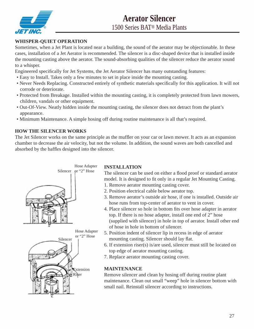
WHISPER-QUIET OPERATIONSometimes, when a Jet Plant is located near a building, the sound of the aerator may be objectionable. In these cases, installation of a Jet Aerator is recommended. The silencer is a disc-shaped device that is installed inside the mounting casting above the aerator. The sound-absorbing qualities of the silencer reduce the aerator sound to a whisper.Engineered specifi cally for Jet Systems, the Jet Aerator Silencer has many outstanding features:• Easy to Install. Takes only a few minutes to set in place inside the mounting casting.• Never Needs Replacing. Constructed entirely of synthetic materials specifi cally for this application. It will not
corrode or deteriorate.• Protected from Breakage. Installed within the mounting casting, it is completely protected from lawn mowers,
children, vandals or other equipment.• Out-Of-View. Neatly hidden inside the mounting casting, the silencer does not detract from the plant’s
appearance.• Minimum Maintenance. A simple hosing off during routine maintenance is all that’s required.
HOW THE SILENCER WORKSThe Jet Silencer works on the same principle as the muffl er on your car or lawn mower. It acts as an expansion chamber to decrease the air velocity, but not the volume. In addition, the sound waves are both cancelled and absorbed by the baffl es designed into the silencer.
Aerator Silencer1500 Series BAT® Media Plants
INSTALLATIONThe silencer can be used on either a fl ood proof or standard aerator model. It is designed to fi t only in a regular Jet Mounting Casting.1. Remove aerator mounting casting cover.2. Position electrical cable below aerator top.3. Remove aerator’s outside air hose, if one is installed. Outside air
hose runs from top-center of aerator to vent in cover.4. Place silencer so hole in bottom fi ts over hose adapter in aerator
top. If there is no hose adapter, install one end of 2” hose (supplied with silencer) in hole in top of aerator. Install other end of hose in hole in bottom of silencer.
5. Position indent of silencer lip in recess in edge of aerator mounting casting. Silencer should lay fl at.
6. If extension riser(s) is/are used, silencer must still be located on top edge of aerator mounting casting.
7. Replace aerator mounting casting cover.
MAINTENANCERemove silencer and clean by hosing off during routine plant maintenance. Clean out small “weep” hole in silencer bottom with small nail. Reinstall silencer according to instructions.
Silencer
Silencer
Extension Riser
Hose Adapter or “2” Hose
Hose Adapter or “2” Hose
27

LIMITED WARRANTY
MODEL 3 G UV DISINFECTION UNIT
This warranty is given by Jet Inc. for the benefit of the first purchaser of the product to which the warranty applies. The warranty applies only to those parts which are manufactured and delivered by Jet Inc. The warranty is that the parts manufactured and delivered by Jet Inc. will be free from defects in the material or workmanship under normal use and service according to the Installation and Operating Instructions for the time specified below. In the event of a failure of a part due to such a covered defect, Jet Inc. will repair or replace, at its option, the defective part at its factory located at 750 Alpha Drive Cleveland, OH 44143. At the option of Jet Inc., repairs or replacement may be made at the site of equipment installation. The part must be returned to the factory at the expense of the person claiming the benefit of the warranty unless Jet Inc. elects to repair or replace the defective part at the installed site. The warranty shall be for a period of twenty four (24) months after the date of delivery of the product, or the specified service life of the product, whichever period is the shortest. All products for which warranty claims are filed must be returned as provided above to the factory within thirty (30) days from the date of the claimed malfunction in order for this warranty to be effective. The only entity authorized to do any warranty repairs is Jet Inc. The repairs or replacement by Jet Inc. will be accomplished within twenty (20) days from receipt of the defective part(s) at the factory. This warranty is expressed in lieu of all other warranties, expressed or implied, including the implied warranty of fitness for a particular purpose, and of all other obligations or liabilities on the part of Jet Inc., and it neither assumes nor authorizes any other persons to assume for Jet Inc. any other liabilities in connection with the sale of the products. This warranty does not cover parts of products made by others, or products or any part thereof which have been repaired or altered, except by Jet Inc., which shall have been subjected to misuses, negligence, or accident. Jet Inc. shall not be liable for damage or delay suffered by the purchaser regardless of whether such damages are general, special, or consequential in nature whether caused by defective material or workmanship or otherwise, or whether caused by Jet Inc., negligence, regardless of degree.
28
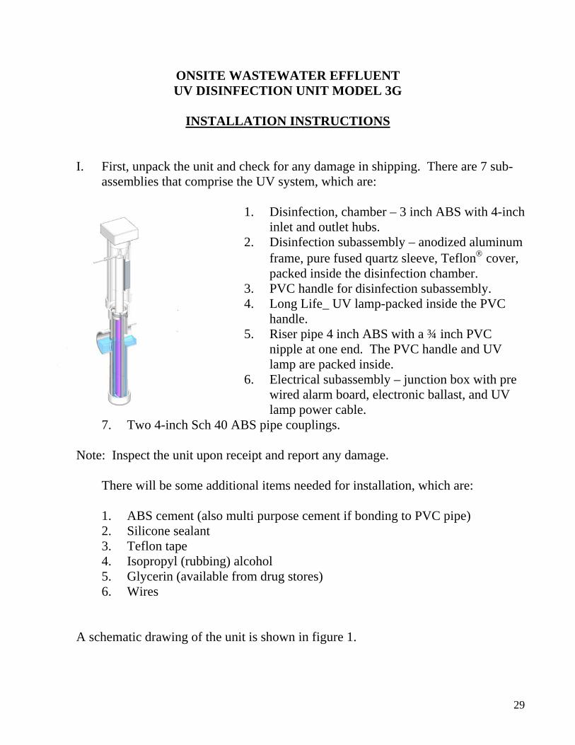
ONSITE WASTEWATER EFFLUENT UV DISINFECTION UNIT MODEL 3G
INSTALLATION INSTRUCTIONS
I. First, unpack the unit and check for any damage in shipping. There are 7 sub-assemblies that comprise the UV system, which are:
1. Disinfection, chamber – 3 inch ABS with 4-inch
inlet and outlet hubs. 2. Disinfection subassembly – anodized aluminum
frame, pure fused quartz sleeve, Teflon® cover, packed inside the disinfection chamber.
3. PVC handle for disinfection subassembly. 4. Long Life_ UV lamp-packed inside the PVC
handle. 5. Riser pipe 4 inch ABS with a ¾ inch PVC
nipple at one end. The PVC handle and UV lamp are packed inside.
6. Electrical subassembly – junction box with pre wired alarm board, electronic ballast, and UV lamp power cable.
7. Two 4-inch Sch 40 ABS pipe couplings. Note: Inspect the unit upon receipt and report any damage. There will be some additional items needed for installation, which are:
1. ABS cement (also multi purpose cement if bonding to PVC pipe) 2. Silicone sealant 3. Teflon tape 4. Isopropyl (rubbing) alcohol 5. Glycerin (available from drug stores) 6. Wires
A schematic drawing of the unit is shown in figure 1.
29

DETAILED STEPS
1. Cut 4-inch riser pipe and lamp handle to meet job needs. Use the 4-inch connection to the pretreatment unit as a reference point. The lamp handle upper end should be slightly below the ¾ inch nipple and the riser pipe.
2. Attach the threaded end of the lamp handle to the 1 inch threaded nipple on the upper end of the disinfection subassembly, which is packed inside the disinfection chamber. Teflon tape should be used to seal the threads. Then remove the disinfection subassembly by pulling the handle upward.
3. Bond the riser pipes and couplings and connect the disinfection chamber to the upstream and downstream (if any) pipes. The unit symmetrical and either port can be used as the inlet (or outlet).
4. Inspect the disinfection subassembly. Using a clean, soft cloth and isopropyl (rubbing) alcohol, clean the Teflon® cover and remove any fingerprints. Then lubricate the rubber gaskets with either water or glycerin.
Note: Do not use silicone or petroleum based lubricants. 5. Slide the disinfection subassembly through the riser pipe into the disinfection
chamber using the handle. Make sure that the subassembly is at a right angle to the inlet and outlet pipes, and that the holes on the upper hub of the subassembly lock into two pins in the disinfection chamber. The orientation is very important for successful UV unit operation.
6. The UV unit operates on 120 VAC single phase (50 or 60 HZ) power and consumes 30 watts. A dedicated 10-15-amp breaker on the main electrical panel should be used for service.
7. An electrical junction wiring diagram is shown in figure 2. Inlet power, ground and alarm wires are fed through conduit to the ¾ inch nipple on the riser pipe. Enough wire should be pulled through the riser pipe to reach about one foot above it.
8. The wires should then be fed through the cord grip on the bottom sides of the electrical junction box. The cord grip can accommodate five 12 AWG wires in addition to those pre-wired.
30

9. Attach the wires to the terminal block as shown in figure 2. The wiring schematic is also shown on the inside of the junction box cover.
10. The alarm contacts are compatible with both normally open (N/O) and normally closed (N/C) external alarm units (furnished by others). They accommodate up to 120 volts and up to 500 milliamps. Select the common and the contact that complies with the receiving alarm panel.
11. Tighten the cord grip, attach the four pin connector to the UV lamp and carefully lower the lamp through the handle. Be careful to not damage the quartz tube during insertion.
12. Lower the ballast so that it is loosely attached to the PVC handle by the two tie wraps.
13. Place the electrical junction box on top of the 4 inch riser pipe. Tuck excess wire into the riser pipe.
14. Turn the breaker at the main electrical panel on. The LED light on the side of the junction box should now be on, indicating that the unit is operational.
15. Fill the recess in the bottom of the electrical junction box where the wires feed into the cord grip with silicone sealant. Then replace the electrical junction box lid.
INSTALLATION ALTERNATIVES
1. In ground – couple the 4-inch inlet
to the exit pipe of the pretreatment unit, and couple the 4-inch outlet to the drain field pipe.
2. Pump tank – couple the UV unit inlet pipe to the pretreatment unit exit pipe at the entrance of the pump tank.
3. Figure 1 shows that the electrical junction box should be above ground level. If this should pose a problem with lawn mowers,
the box could be placed below grade in an irrigation or water meter box; or an artificial rock could cover the junction box.
The Junction box is rated NEMA 4X. However, to be safe it should be protected from flooding. In pump tank installations, care should be taken to prevent flooding of the junction box or the ballast suspended below it.
31

JET UV 3G DISINFECTION MAINTENANCE AND SERVICE
The UV 3G disinfection unit is designed to provide long service life. It is recommended that the UV lamp be replaced every two years to insure proper disinfection. To replace the lamp: 1. Turn off the dedicated breaker located in the main
electrical panel that supplies power to the UV system. 2. Remove the electrical junction box and ballast from the
UV disinfection chamber and carefully set it aside. 3. Using the power line connected to the UV lamp, lift the
lamp out of the disinfection subassembly. 4. Disconnect the four pin connector attaching the power line to the
UV lamp. 5. Connect the new lamp to the four pin connector and completely
lower the new lamp into the UV subassembly. 6. Tuck the remaining power line into the riser pipe. 7. Make sure the ballast is still in position on subassembly handle and
he back side of the control center enclosure into the top of the riser pipe. Turn on the dedicated bre
insert the plastic section on t
8. aker located
.
It is recommended that the disinfection subassembly
ion
in the main electrical panel that supplies power to the UV system
be removed and serviced a minimum of once per year to insure propereffluent disinfection. To clean the Teflon® sheath and disinfectsubassembly: 1. Clean with a soft sponge and detergent. 2. Use isopropyl alcohol on a soft cloth to remove difficult stains like
finger prints and other films.
32
TRUCK TALK
THE TRUCKTo start and expand their Jet Business, distributors need adequate trucks for tank delivery and setting. For this job, the lightest truck recommended would be equivalent to the International 1700 series, the Ford 600 series, or GMC 5700 models.Tandem axle trucks may be desirable if heavy mud or snow conditions are frequently encountered. Tandem axles generally perform well when the going is rough but they have the disadvantage of being difficult to maneuver in tight areas. If the majority of the tank settings will be in built up areas or where little space is available, the single axle truck may be the best choice.All trucks should be capable of “off the road” operations and should have adequate bumpers so that they may be either pushed or pulled by excavating equipment. Traction tires are definitely recommended on the rear axle.Truck beds should have adequate space for Jet Tank Castings as well as the tank lid, riser sections, mounting castings, tools and in many cases, a sampling box.
TANK HANDLINGTruck mounted equipment capable of handling the tank or tank sections is necessary. This equipment should be capable of lifting the castings from the truck bed, moving them over the excavation and setting them in place. Preferably, the equipment controls should be located at the rear of the truck. The job should be accomplished either hydraulically, mechanically or electrically without depending on any manual power. Equipment which requires the driver to push the load away from the truck by hand should not be considered.Jacks or outriggers will be needed for supporting the truck when the load is over the excavation.
TRAILERSTo stretch delivery capacity and cut costs, a trailer to carry castings can be towed by the tank delivery truck. Trailers can be loaded and unloaded by the tank handling equipment on the truck and can be used on jobs which are close together or which require multiple castings. If two jobs are on the same route, the loaded trailer can be left at the first job and then unloaded and towed home on the delivery truck’s return. The trailer and bed should be of a size and capacity to at least carry a load equal to that of the delivery truck. If trailer use is anticipated, the size of the truck engine and power train should be increased by 17,000 pounds. This assumes a 14,000 pound maximum trailer load and a trailer weight of 3,000 pounds. Be sure to tell your dealer this is a “towed load.”
STATE REGULATIONSBefore making any arrangements for delivery equipment, check your state’s trucking regulations with the State Highway Patrol, particularly in regard to overall length and axle loads.
33

750 Alpha Dr. Cleveland, OH 44143 USA Phone: 440.461.2000 Fax: 440.442.9008 [email protected] www.jetincorp.com
JET, JET AERATION, BAT, AIR-SEAL, BIO JET-7, CHLOR-AWAY and JET-CHLOR are registered trademarks of JET INC. 34
TRUCK REQUIREMENTS
Recommended truck specifications for the various plants are listed in bold type. Extra capacity, even above these recommendations, is always desirable. Absolute minimum specifications are given in parentheses. No commercial plant can be hauled in one trip with-out a trailer, how ever the recommended 6’10” height allows for delivery of two commercial castings per trip while anything less allows only room for one. The split home tank is normally hauled stacked. If a 19’8” truck bed is available, it could be hauled end to end, thus reducing the height requirement.
Requirements Commercial Plant Castings
Complete Home Plant (One Pc. Tank)
Complete Home Plant (Split Tank)
Length (Truck Bed)
14’-0”(13’-0”)
13’-0”(10’-0”)
13’-0”(10’-0”)
Width (Inside Frame)
7’-6”(7’-4”)
6’-8”(5’-6”)
6’-8”(5’-6”)
Height (Bed to Inside of Hook)
6’-10”(6’-4”)
6’-4”(5’-7”)
6’-4”(5’-7”)
Boom Extension (Beyond Truck Bed)
12’-0”(10-0”)
9’-0”(9-0”)
9’-0”(9-0”)
Lifting Capacity (Per Single Lift)
10,000 lbs.(10,000 lbs.)
10,000 lbs.(10,000 lbs.)
5,000 lbs.(5,000 lbs)
CASTING DATAThe data listed here is only for the largest single casting in any category.
Category Length Width Height Weight Heaviest Casting
Weight Complete Plant with Riser
Commercial Plant 12’-10” 6’-10” 2’-10” 9,180 lbs. Diffusers with each size Plant
Home Plant (One Piece Tank) 9’-10” 4’-11” 5’-0” 6,660 lbs. 9,290 lbs.
Home Plant (Split tank) 10’-0” 4’-11” 3’-2” 4,680 lbs. 9,450 lbs.
Home Plant(One Piece Tank
with Add -on)14’-10” 5”-1” 5’-9” 14,000 lbs. 15,000 lbs.

BIO JET-7® WASTEWATER SYSTEM MAINTENANCE INSTRUCTIONS
This is the new BIO JET-7 SystemAs the primary decomposers of all organic waste, bacteria reduce in-fluent solids and organics to harmless compounds of water and car-bon dioxide. All wastewater treatment systems, from septic tanks to large municipal and industrial plants, are designed around this bacterial function.The failure of a wastewater treatment system to meet its design param-eters or discharge permit requirements is usually due either to 1.) an insufficient bacterial population, or 2.) organic wastes which the exist-ing bacteria cannot digest.BIO JET-7® has been specifically designed to replenish and supple-ment bacterial populations and functions in wastewater treatment sys-tems. BIO JET-7® actually contains scientifically developed and pat-ented bacteria strains which quickly degrade such difficult compounds as detergents, tissue, fats, oils and greases. They also digest other waste constituents such as starches, cellulose, protein and vegetable gum. Regular application of BIO JET-7® to your system will help achieve the system design effluent parameters while overcoming such related problems as odor, fouled drain fields and excessive solids accumula-tion.In addition to dramatic improvements in system performance through improved biological oxidation of organics, you can substantially re-duce your plant maintenance costs with regular use of BIO JET-7®. Savings through reduced labor, chemicals and equipment replacement normally parallel plant improvement.Regular applications of BIO JET-7® will control wastewater treatment problems and reduce your maintenance costs while dramatically im-proving the performance of your wastewater treatment system.
Instructions for UseBIO JET-7® is available in one-gallon bottles, five-gallon pails and 55-gallon drums. No pre-mixing is required. Simply shake well and apply directly to your wastewater treatment system according to instructions. DO NOT ALLOW YOUR BIO JET-7® TO FREEZE - temperatures below freezing will reduce the number of bacteria by half. In larger systems, BIO JET-7® should be introduced by a chemical metering pump, or by a drip feed device. For best results, simply follow the detailed instructions provided in this brochure for your specific type of wastewater treatment system or facility. For facilities not covered here, or for more information, contact your local JET dealer. Or contact JET INC., 750 Alpha Drive, Cleveland, OH 44143.
How to Determine Accurate Continuous Feed Rates for BIO JET -7Routine maintenance requires daily feeding of BIO JET-7® into waste-water treatment systems at various parts per million (ppm) dosages, depending on the type and capacity of your system. One ppm of BIO JET-7® translates into 1 gallon of BIO JET-7® per million gallons of water. In most cases, daily feeding rates of 2 ppm are required. This is equal to 2 gallons of BIO JET-7® liquid for every million gallons of water in your wastewater treatment system.
Why Wastewater Treatment Systems Become UpsetThere are several reasons why wastewater treatment systems become upset and why imbalances occur. Bacteria are living or-ganisms. Some care is required to maintain an environment for them to live and work as decomposers of waste. Like human be-ings, bacteria must have oxygen to breathe. They cannot live in extremely cold or hot temperatures, nor in acid or strong alkaline solution. For example, pH is a common problem in wastewater and should be maintained between 6 and 9 with an ideal pH of 7.5. Temperature shock is also common. Bacteria can live in wastewaters with varying temperatures from 45° to 100° F. Op-timum temperatures would be 75° to 90° F. Oxygen is required by bacteria to oxidize waste with minimal requirements of 1 milligram per liter, and 2 to 3 milligrams per liter for overcom-ing shock loads. Toxic chemicals also kill bacteria and diminish their population. BIO JET-7® provides numerous benefits due to its ability to degrade detergents, fats, oils and greases, and other compounds. However, it cannot overcome severe toxic loadings of hydrocarbons, phenolic compounds, or household pesticides. An additional factor in poorly operating wastewater plants is hy-draulic overload. Hydraulic overload occurs when wastewater passes through the plant too rapidly and does not allow the bac-teria adequate time to eat and digest or metabolize food.BIO JET-7® not only improves system performance. It can also overcome shock loads and kills. BIO JET-7® rapidly reestablish-es a healthy bacterial population with improved waste oxidation capabilities, insuring continuous optimum plant performance when applied to properly designed plants in which parameters for oxidation are maintained.
Required Environment for Maximum Bacteria FunctionpH: 6 to 9Temperature: 45° to 100° F.Dissolved oxygen: 1 to 3 milligrams per liter Retention time: 6 to 12 hours, or longer
How to Seed an Inactive Wastewater Treatment SystemBIO JET-7® establishes and reestablishes biological colonies in new or killed systems.Application Rate: initially, dose with 2 to 3 times the feed rate that is normal for your type of wastewater system. Dose at this rate for 2 or 3 days. Once the bacterial colony has been estab-lished, follow the normal maintenance dosage recommended in this brochure for your type of system.
35

Application and Maintenance InstructionsWastewater Treatment PlantsConventional Activated Sludge Plants - Contact Stabilization Plants - Municipal Plants - Extended Aeration Plants - Package Plants - And All Other Treatment PlantsProblems are usually caused by hydraulic or organic overload-ing, excess grease loading, poor organic solids reduction and inadequate bacterial population. Application of BIO JET-7® to wastewater treatment plants improves oxidation of organic solids, settling and reduces grease accumulations. It can also reduce BOD, COD and SS in the final effluent.
For normal maintenance and proper operation: add 1 gallon of BIO JET-7® daily for each million gallons of influent.For poorly operated systems: maintain feed rate of 1 gallon per day.
Aerobic Sludge DigestorsProblems commonly associated with aerobic digestors are usually caused by overloading, toxic wastes and incorrect pH, which results in lack of settling and poor organic solids reduction.Application of BIO JET-7® to the digestor improves oxidation of fats, oils, grease and associated organic waste. It also improves settling, solids reduction and odor control. Add 2 ppm of BIO JET-7® daily based on the volume of the digestor.For normal maintenance and to keep the system operating prop-erly: continue to add BIO JET-7® at the above rate of 2 ppm
Anaerobic Sludge DigestorsProblems are usually caused by excess grease loading and incorrect pH, which results in scum and grease blankets, excess noxious odors and poor solids reduction and settling. Adjust alkalinity to correct range by the addition of sodium bicarbonate or soda ash in conjunction with the addition of BIO JET-7® to improve settling, solids reduction, odor control, and reductions in scum blankets and grease accumulations. Add 2 ppm of BIO JET-7® daily based on the volume of the digestor.For normal maintenance and to keep the system operating prop-erly: continue to add BIO JET-7® at the above rate of 2 ppm.
Collection Systems - Lines - Wet Wells - Lift StationsProblems commonly associated with collection systems are grease, fats, oils and organic solid deposits in lines, hydrogen sulfide line cor-rosion, hydrogen sulfide odor, and organic odors. Addition of BIO JET-7® to collection systems provides reduction or elimination of grease, oils and fat deposits, hydrogen sulfide corrosion problems, line corrosion, organic odors, and hydrogen sulfide odors. Add BIO JET-7® by feeding into the line preceding the lift station or wet well at a continuous rate of 2 ppm (based on daily flow) until grease, fats, oils and organic solid deposits are gone or greatly reduced. If feeding is not practical: pour 1 gallon directly into the wet well.For normal maintenance and proper operation: add 1 gallon of BIO JET-7® every week by feeding into the line preceding the station or pouring directly into the wet well or lift station.
Trickling Filters andRotating Biological Contactors (RBC’s)Problems associated with system operations are excessive buildup of solids and grease on filters and RBC surfaces because of ineffec-tive biological oxidation. The results are noxious odors, ponding, ex-posed media, and non-compliance. Addition of BIO JET-7® greatly enhances biological oxidation of difficult organics such as fats, oils and grease. It can also reduce BOD, COD and SS in the final effluent. Improved biological oxidation of organics results in reduced organic fouling of trickling filters and RBC surfaces. Add 2 ppm BIO JET-7® at inlet end of system.For normal maintenance and to keep the system operating prop-erly: continue to add BIO JET-7® at the above rate of 2 ppm.
Plant Capacity
(Gallons per day)Initial Dosage
(Each day for 3 days)
Normal Maintenance Dosage
(Each day)
1500- 25,000 12 ounces 4 ounces
25- 50,000 24 ounces 8 ounces
50- 75,000 36 ounces 12 ounces
75-100,000 48 ounces 16 ounces
100,000-1 million 48 ounces for each 100,000 gallons capacity
16 ounces for each 100,000 gallons capacity
1 million or more 3 gallons for each million gallons capacity
1 gallon for each million gallons capacity
Add BIO JET-7® in the plant inlet or in the collection system as close to the plant inlet as possible. If neither the inlet nor collection system are accessible, add BIO JET-7® to the plant’s first treatment stage.Note: Recommended doses of BIO JET-7® in the above table are for plants which are loaded at or near design capacity but are not operating properly.For plants in very bad condition - that is, plants with noxious odors, floating solids, heavy grease build-up - the “Initial Dos-age” may be doubled and the “Normal Maintenance” dosage kept the same.For periodic hydraulic or organic plant overloading (i.e., too much liquid going into the plant, or for cases where the influent is too strong), the “Normal Maintenance” dosage may be doubled.For faster clean-up of isolated problem areas (pumping sta-tions, settling tanks, aeration tanks), triple the “Initial Dosage” and apply it directly to the problem area.For normal maintenance and to keep the system operating properly: follow the above “Normal Maintenance Dosage’.”
Aerated and Non-Aerated Lagoons and Polishing PondsLagoons and ponds fail to perform because of inadequate bacte-rial population, inadequate dissolved oxygen (DO should be .5 ppm to 2 ppm), pH shock (pH must be between 6 and 9, with 7.5 being ideal), temperature shock (wastewater temperature should be between 45°-100° F., the ideal temperature is 75°-90° F.), toxic waste which kills bacteria, and heavy grease loading (look for grease on the surface).To reestablish effective biological oxidation following system kills or shocks, use BIO JET-7® as follows: add the lagoon vol-ume to the daily inflow. For every million gallons of this total, add 3 gallons of BIO JET-7® each day for 3 days, and 1 gallon each day for the next 4 days. 36

Imhoff TanksBecause of the process, Imhoff Tanks experience a variety of problems, including heavy concentrations of grease, inadequate decomposition of sludge, heavy solids accumulation, and nox-ious odors.Augmentation of the tank with BIO JET-7® greatly improves biological oxidation and reduces or eliminates grease, oils, fats, and odors. It also reduces BOD, COD and SS. AddBIO JET-7® by feeding into the line preceding the wet well or lift station at a continuous rate of 2 ppm based on daily flow. If feeding is not practical: pour 3 gallons per day for the first 3 days directly into the wet well or lift station.For normal maintenance and to keep the system operating properly: continue to add BIO JET-7® at the above rate of 2 ppm.
Industrial Wastewater SystemsMost of the problems associated with industrial wastewater systems are caused by waste streams that are difficult to de-grade, lack of nutrients, inadequate dissolved oxygen, pH up-sets, temperature shocks, inadequate bacteria population, and toxic kills.BIO JET-7® has proved very effective in industrial waste-water plants where performance above operating parameters is desired. BIO JET-7® will provide settleability, rapid plant recovery, and reductions in final effluent for BOD, COD and suspended solids.If you are experiencing difficulty in achieving desired plant performance, or if you require the use of such costly addi-tives as defoamers, polymers, or ferric chloride: the use of BIO JET-7® combined with recommendations from Jet’s tech-nical representatives should prove most beneficial in achieving optimum performance and chemical cost savings.For normal maintenance: dose according to directions for the type of system in use. See “Instructions for Aerated and Non-Aerated Lagoons:”
Stabilization PondsProblems commonly associated with ponds include noxious odors, flow variation, heavy grease loading, and surface accu-mulations.Use of BIO JET-7® in ponds greatly improves biological oxida-tion of organic wastes. It reduces or eliminates odors and grease and maintains stability.Use a chemical metering pump or drip feed device to add BIO JET-7® directly into the inlet of the pond or basin. If this is impractical, BIO JET-7® may be added directly to the basin at a rate of 2 ppm of daily flow.For normal maintenance and to keep the system operating properly: continue to add BIO JET-7® at the above rate to 2 ppm.
Agriculture Lagoons or Manure PitsProblems commonly associated with agricultural lagoons or manure pits include crusting of surface area, poor separation of solids and foul odors. Addition of BIO JET-7® effectively liquifies waste and provides significant odor reduction. Add BIO JET-7® by diluting 1 pint of BIO JET-7® with 10 gallons of warm water for each 1000 square feet of area. Apply daily for first week.For normal maintenance: apply same dosage once each week.
Septic Tank SystemsProblems associated with maintaining biological activity in household wastewater systems result from shock loading caused by household cleaners, detergents, chlorines and disinfectants, heavy grease loads, and vacation periods when the bacteria supply does not receive its normal waste supply. These problems cause noxious odors, wastes that are discharged before they are completely treated and tanks that become overloaded with organic wastes.Home wastewater treatment systems rely on a healthy, active bacteria population to break down and degrade organic solids in the waste. Once the bacteria population has been killed or drastically reduced, additional problems develop in the total system, including toilet back-up, clogged cesspools, filters, leaching fields, and leaching beds.Application of BIO JET-7® to household systems provides effective and continuous biological oxidation of all household waste products. BIO JET-7® is specifically formulated to degrade fats, oils, greases, cellulose, and detergents. Use of BIO JET-7® results in stable opera-tion and minimizes or eliminates most problems.Important: BIO JET-7® does not eliminate need for tank pumping. Tanks should be pumped every 2 years. Add BIO JET-7® by pouring it directly into the tank or sink drain, or by flushing it down the toilet.For sluggish, blocked tanks: add 1 gallon of BIO JET-7®. NOTE: If your tank has not been pumped for 2 years, do so before adding BIO JET-7®.For normal maintenance and to keep the tank operating properly: add 1 pint of BIO JET-7® weekly.
Soil Absorption Fields, Cesspools, and Sand FiltersInadequate biological activity in the septic tank allows partially treat-ed organic solids and heavy grease loads to flow into the disposal area. This causes blockage of the soil in both bottom and side wall areas, eventually clogging the entire system. Sewage backups, surfacing and costly repair will soon follow. The addition of BIO JET-7® provides effective and continuous biological oxidation of organic solids in the disposal area. Blocked or sluggish disposal areas require twice the initial dosage and double the normal maintenance dosage required for septic tanks. If the cesspool has not been pumped in 2 years, pump before treating.Add BIO JET-7® by pouring it directly into the cesspool or distribu-tion box. If your system does not have a distribution box, BIO JET-7® may be poured directly into the tank, sink drain or flushed down the toilet.For blocked or sluggish disposal areas: add 2 gallons of BIO JET-7®.For normal maintenance and to keep the disposal area operating properly: add 1 quart of BIO JET-7® weekly.A neglected septic tank system fails much sooner than a well main-tained system. A conscientious maintenance program of pumping the septic tank every 2 years and regular BIO JET-7® applications will greatly extend the life of the system.
Pit and Concrete Vault ToiletsBoth types of toilets have a limited amount of natural bacterial activ-ity. Therefore, solids accumulate and cause odors. Augmentation of these facilities with BIO JET-7® establishes and maintains biological oxidation, reducing solids and minimizing or eliminating odors.If possible, pump out the facility before adding BIO JET-7®.To properly start bacterial action: add 1 gallon of BIO JET-7® and cover the solids with 3” of water.For normal maintenance and proper operation: add 1 pint of BIO JET-7® weekly. Add water as necessary to keep solids cov- 37

750 Alpha Dr. Cleveland, OH 44143 USA Phone: 440.461.2000 Fax: 440.442.9008 [email protected] www.jetincorp.com
JET, JET AERATION, BAT, JET AIR-SEAL, BIO JET-7, CHLOR-AWAY and JET-CHLOR are registered trademarks of JET INC.
Grease TrapsGrease traps are designed to prevent large volumes of grease from entering the waste system. Grease and fats are not water soluble. BIO JET-7® bacteria are capable of altering the physi-cal and chemical properties of grease, making it water soluble. The major problems experienced with grease traps are odor, solid grease mats on the surface and cleaning difficulty.For sluggish, blocked, odorous grease traps: add 1 quart of BIO JET-7® initially to each trap.If the trap is not accessible: pour BIO JET-7® into the nearest drain leading to the trap.For normal maintenance and proper operation: add 1 pint of BIO JET-7® to each trap once a week. The drain(s) leading to the trap and the trap itself may need treatment. If you add BIO JET-7® directly to the trap and problems aren’t solved, the drain(s) must be treated in addition to the trap. First, divide 1 quart by the number of drains leading to the trap and pour this amount down each drain, and flush with water.For normal maintenance and proper operation: divide 1 pint by the number of drains leading to the trap and pour this amount down each drain once a week. If possible, apply during a weekend or period of low flow.
Drain Lines, Down Pipes and SumpsAccumulations of grease, fats, scum, sewage, and leaf debris cause blocked lines and noxious odors. BIO JET-7® degrades fats, oils, grease, and organic solids. The use of BIO JET-7® minimizes or eliminates most problems. For sluggish or blocked flows: pour 8 ounces of BIO JET-7® down the drain line, down pipe or in the sump.For normal maintenance and proper operation: add 2 ounc-es of BIO JET-7® twice weekly. Apply one treatment during a weekend or period of low flow.
Holding Tanks and Dump StationsA continual buildup of solids in these facilities quickly causes odors. Normal maintenance with BIO JET-7® prevents the for-mation of noxious odors, enhances biological oxidation and de-creases solid buildup.To control odors and limit solids buildup in tanks up to 200 gallons capacity: add 1 quart of BIO JET-7® for each 50 gal-lons of tank capacity.For tanks over 200 gallons: add a total of 1 gallon of BIO JET-7®. For normal maintenance of tanks over 200 gallons: add 1 pint of BIO JET-7® each week.After each tank pumping: add 1 gallon of BIO JET-7® and 1 pint weekly thereafter.For tanks under 200 gallons: add 1 quart of BIO JET-7® after each tank pumping; no further dosing is required.
Fish HatcheriesAmmonia and decaying feces and food cause fish fatalities, slow growth and poor reproduction.BIO JET-7® keeps fish healthy, reduces ammonia levels to safe levels and promotes complete digestion of all excess food waste and feces.For fish hatchery problems such as ammonia concentrations over .5 ppm, nitrate concentrations over 1.0 ppm, floor of race-way covered with food, feces and slime or algae: add 1 gallon of BIO JET-7® for each million gallons of water in the system.For normal maintenance and proper operation of flow-through systems: maintain a concentration of 1 gallon of BIO JET-7® for each million gallons in the total system on a constant basis. (That is, for every million gallons of water added, add 1 gallon of BIO JET-7®.) Use a chemical metering pump or drip feed device.For normal maintenance and proper operation of recirculating systems: add 1 gallon of BIO JET-7® for each million gallons of water initially in the system. Thereafter, add 1 gallon of BIO JET-7® for each million gallons of water added to the system.NOTE: BIO JET-7® may initially exert a high oxygen demand on the system. While applying BIO JET-7®, monitor dissolved oxygen levels in the system and maintain proper levels. Proper oxygen lev-els can be maintained by increasing aeration or flow-through during this period or by temporarily decreasing the fish population prior to treatment with BIO JET-7®.
Composting ToiletsCompost toilets usually have very little bacterial activity. To start bacterial action in a compost toilet, dilute 1/2 gallon of BIO JET-7® with 1 /2 gallon of warm water and pour it on the bed of peat moss, sawdust or woodchips. Then, cover the bed with 3” of water.For normal maintenance and proper operation: add 1 /2 pint of undiluted BIO JET-7® every week. Toilets with heaters normally maintain temperature around 95°-100° F., which is perfect for BIO JET-7®. Heaters set to higher temperatures should be adjusted so they do not exceed 130° F., as higher temperatures may kill BIO JET-7® bacteria.
Jet Inc., the Company Behind BIO JET-7®Jet Inc. was founded in 1955. Headquartered in Cleveland, the com-pany is an international leader in wastewater treatment. Products beside BIO JET-7® include the revolutionary new BAT® Process Plants and Commercial extended aeration plants, JET CHLOR® Disinfectant Systems (tablet feeders and chlorine tablets), CHLOR-AWAY® Dechlorination Systems, Jet Pressure Dosing, AIR-SEAL Diffusers®, Lift Stations, Liquid Level Alarms, Controllers, and a broad range of other wastewater treatment products and equip-ment.For more information about BIO JET-7® and any other Jet system, equipment and products, contact Jet Inc., Customer Service Depart-ment, 750 Alpha Drive, Cleveland, Ohio 44143.
38


![APA1718]AGENDA... · Imagiologia Prof. Doutor Jorge Campos clinica.imagiologia@ Nuno Rodrigues Endocrinologia 44143 Prof. Doutor Mário Mascarenhas/ Prof. Doutor J. Martim Martins](https://img.dokumen.tips/doc/110x75/5bedf79609d3f2a7378c4988/apa1718agenda-imagiologia-prof-doutor-jorge-campos-clinicaimagiologia.jpg)