Embed Size (px)
Citation preview
January/February 2007 4544 Official
requires that an adequate flow be maintained to meet thereal demand on the system and that the velocity of the waterbe within acceptable limits to avoid erosion, water hammer,and excessive noise. These factors limit how small the diam-eter of pipe can be used.
Velocity, Not Pressure Loss, Usually Determines Sizing
Knowing that smaller pipe can improve perfor-mance, we recognized that we had to consider both veloci-ty and pressure drop due to friction losses. While is it cer-tainly possible to install more pipe, for most single storyhomes under 3000 ft2 and two story homes under 4000 ft2,the maximum equivalent length of pipe from the hot watersource to the fixture will likely be less than 100 ft. As a pointof reference, the median size of new homes in 2006 isapproximately 2500 ft2.
2´,1/2˝h
2´,1/2˝h
3´,1/2˝u
6´,1/2˝h
6´,1/2˝h12´,1/2˝h
15´,1˝h9´,1/2˝h
2´,1/2˝h
2´,1/2˝h 4´,1/2˝h
3´,3/4˝h
5´,3/4˝h
1.5´,1˝u1.5´,1˝h
4´,1˝d
3´,1/2˝u
5´,1/2˝d
2´,1/2˝h
2´,1/2˝u
10´,1/2˝h
12´,1/2˝d
15´,1/2˝h
3´,1˝h
2´,1˝h
2´,1/2˝u 2´,1/2˝h5´,1/2˝d
5´,1/2˝h
18´,1/2˝h
3080 sq.ft. One Story
6´,1/2˝hvan1
van1
tub
van2
van2
van3
sh
w
shtub
dwks
5´,1/2˝d
5´,1/2˝d
5´,1/2˝d
20´,1/2˝d
15´,1/2˝d
Nook
Family
Dining
Living
Bed 2
Bed 3
Bath 2Library
Garage
Bath 3
Walk-In
M.Bath
M.Bedroom
3rd CarGarageSpace
Service Area
Kitchen
Figure 1 Example 3080 ft2Single Story House
To illustrate this point regarding pipe length, the3080ft2 single story house shown in Figure 1 has a maxi-mum run from the water heater to the tub in the furthestbathroom (lower left corner) of approximately 88 lineal feetof pipe. This house was chosen because it portrays a veryspread out distribution system. Many new houses do nothave runs of this length.
Assuming the line runs through the attic there wouldbe five “tees,” two “Ls” and several couplings dependent onthe type of pipe. These fittings would add another 18 to 20feet of equivalent length to this part of the system for a totallength of 106 to 108 feet.
Since PEX tubing has become a dominant system inCalifornia for single-family homes, we will use it in the fol-lowing example. In order to achieve a flow of 4 GPM to thetub/shower at a velocity under 10 ft/sec a 1/2-inch tube isthe minimum size that can be used. The friction loss for thissegment — assuming the 1/2-inch is used throughout —would be 20.8 psi X 1.08 (the added length) = 22.5 psi. Thisis no problem for most houses with their 50-60 psi pressure.The velocity in the 1/2-inch tube would be an acceptable7.24 ft/sec.
Residential Hot WaterDistributionSystemResearchSuggestsImportant CodeChangesBy G. Klein, CEC and R. Wendt, ORNL
BackgroundThe California Energy Commission and supportingresearch organizations have been investigating theimpact of the hot water distribution system’s design
on the overall energy and water performance of the systemin residential buildings. While our research and investiga-tions are likely to lead to modifications in the Building EnergyEfficiency Standards portion of California’s BuildingStandards Code (Title 24), a number of potential ways toenhance the performance of these systems is influenced orgoverned by the requirements of plumbing codes, includingthe Uniform Plumbing Code (UPC).
Based on our research, the key factor in determin-ing the performance of hot water distribution systems is todesign and build them to have the smallest volume of waterwithin that portion of the system between the plumbing fix-ture and the source of hot water. The length and the inter-nal diameter of the pipe(s) determine the volume of watercontained within the distribution system. Systems with theleast internal volume waste the least amount of energy andwater. They also typically provide hot water to the plumbingfixture with the shortest waiting period — typically the mostimportant consideration to the hot water user.
Unfortunately, the current plumbing codes do notdifferentiate between hot and cold potable water piping inthe design and installation of a distribution system. Withoutthis differentiation, current hot water distribution systemstypically become over-sized while following the guidance pro-vided by plumbing codes. Excessive pipe size has little or nonegative water or energy conservation impact on cold watersystems but it is a big factor in reducing the performance ofhot water distribution systems.
The purpose of this article is to share with you someof the implications of potential changes to plumbing codesstemming from our research.
Right Sizing“Right sizing” of hot water distribution systems
entails using the smallest diameter pipe that will provide ade-quate flow (at the available water pressure) to meet the realdemand on the systems at an acceptable velocity. The UPCcurrently dictates a maximum velocity of 5 ft/sec for copper,and 10 ft/sec for other, hot water piping. Using the smallestdiameter pipe allowed by code has several benefits: it willreduce the water and energy wasted down the drain while theuser waits for hot water to arrive; it will reduce the tempera-ture drop during the hot water event; and it will minimize theenergy wasted as the water standing in the pipe betweendraws cools down to ambient. However, right sizing also
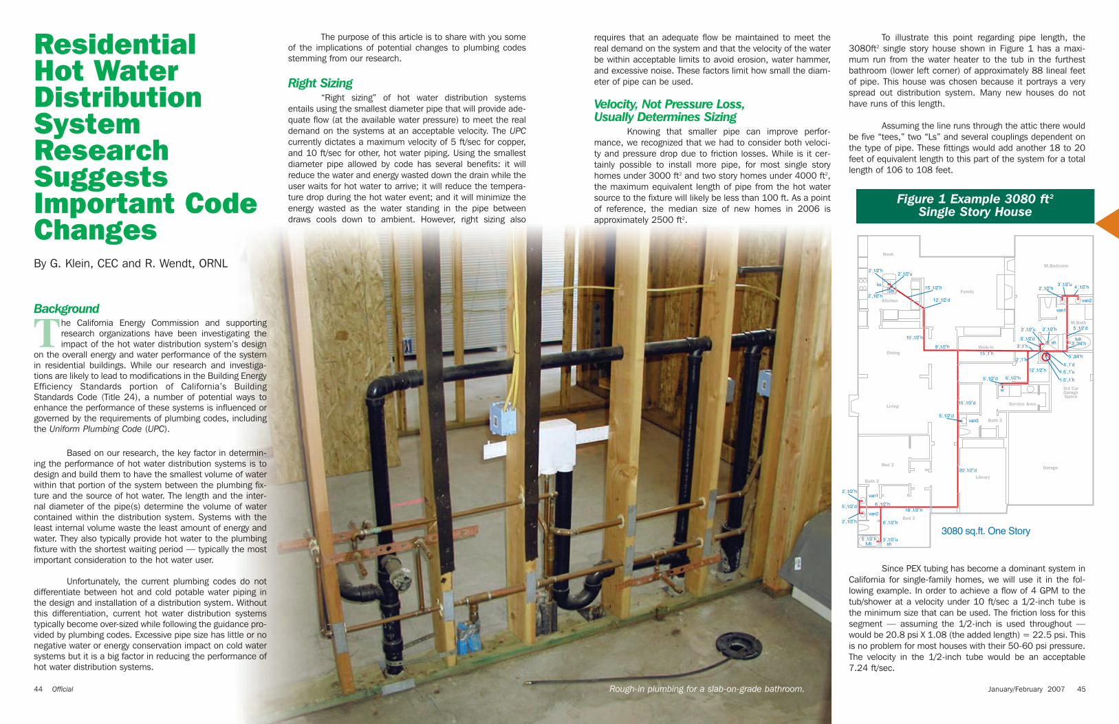
Rough-in plumbing for a slab-on-grade bathroom.
Tables 2-4, developed by ORNL, provide the velocityof water in various sized pipes of copper, CPVC, and PEX fora range of flow rates. Schedule 40 CPVC, which is not typi-cally used in residential construction, was included becausethe more common CTS pipe does not include 3/8-inch and1/4-inch sizes.
What About Water Hammer, Erosion, and Noise?
By now, some of you are ready to tell us that higher velocities will result in water hammer, erosion, andexcessive noise. So let’s look at how big of an issue these will be.
Water hammer is an audible thump that may result when quick closing valves generate excessive surgepressures that are poorly absorbed by the system. Surgepressure is a sudden spike (actually a series of diminishingspikes) in pressure produced by the abrupt change in veloci-ty of the fluid in the line. The impact of the surge pressuredepends on the velocity of the water, the wall thickness, andflexibility of the pipe material. Note that excessive surge pres-sures can occur in a system without audible water hammer.The Jukowski equation was used to determine the maximumsurge pressure in pipes (see Table 5 below). This equation isthe main equation referenced in the plumbing profession forwater hammer.
As can be seen, higher water velocities increase thesurge pressures. In addition, at a given velocity, the surgepressure for copper is roughly four times that of PEX and twoand a half times that of CPVC for the same diameter pipe.Due to their flexibility, plastic pipes reduce the effect of surgepressure spikes and the resultant water hammer better thanmetallic pipes.
In an effort to control water hammer, engineeringrules of thumb concerning surge pressure came into exis-tence for metallic pipes and generally limited velocities to 4ft/sec with use with quickly operating valves and 8 ft/secdepending on application, which is why these two values arecommonly still used. With the increased use of plastic piping,it would be better to choose velocity limitations based on thecharacteristics of the piping system.
As the velocity of water in pipes increases, internalerosion and excessive noise can occur. At velocities over 5 ft/sec with hot water, cavitation based erosion has beendetermined to eat away at copper pipes, particularly in elbows or joints that were not properly reamed. The veloci-ty of hot water in copper pipes is therefore limited to 5 ft/secin plumbing codes to avoid these phenomena. Over 140˚F,the recommended velocity for copper pipe drops to 2-3 ft/sec.
In the research discussed in the last article(September/October 2006) we reported that wide radiuselbows were better from a water and energy performanceviewpoint than standard elbows. The impact of higher veloci-ties in straight runs and around long radius turns should beinvestigated to determine if increased velocities could beaccommodated with an improved system geometry thatreduces water turbulence and cavitation.
Plumbing codes allow water velocities up to 10 ft/secwith plastic pipe. Efforts are under way to determine maxi-mum velocities for CPVC and PEX, but this may take sometime. A limiting concern is that a surge pressure (Table 5) of150 psi, which occurs with rapid shut off valves, may be get-ting into a danger zone of some fixtures.
Continuous noise during use in piping systems, likeerosion, can be related to cavitation that is created by thevelocity of the water and the geometry of the piping system.Higher water velocities coupled with abrupt changes in direc-tion in the system (elbows and tees) can induce cavitationthat creates turbulence, vibration and generates noise. Rigid
Table 5. Maximum Calculated Surge Pressure in PSI
(This pressure is added to line pressure to determine total pressure)
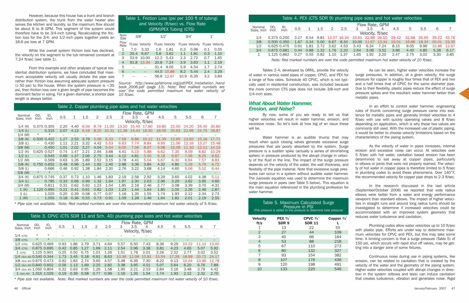
Table 4. PEX (CTS SDR 9) plumbing pipe sizes and hot water velocitiesFlow Rate, GPM
0.5 1 1.5 2 2.5 3 3.5 4 4.5 5 5.5 6 7Velocity, ft/sec
Nominal Sizes, Inch
OD,Inch
ID,Inch
Note: Red marked numbers are over the code permitted maximum hot water velocity of 10 ft/sec.
1/4 0.375 0.250 3.27 6.54 9.81 13.07 16.34 19.61 22.88 26.15 29.42 32.68 35.95 39.22 45.763/8 0.500 0.350 1.67 3.34 5.00 6.67 8.34 10.00 11.67 13.34 15.01 16.68 18.34 20.01 23.351/2 0.625 0.475 0.91 1.81 2.72 3.62 4.53 5.43 6.34 7.24 8.15 9.05 9.96 10.86 12.673/4 0.875 0.681 0.44 0.88 1.32 1.76 2.20 2.64 3.08 3.52 3.96 4.40 4.85 5.28 6.171 1.125 0.862 0.27 0.55 0.82 1.10 1.37 1.65 1.92 2.20 2.47 2.75 3.02 3.30 3.85
Velocity PEX ¾˝ CPVC ¾˝ Copper ¾˝ft/s SDR 9 SDR 11 L1 13 22 552 27 44 1093 40 66 1644 53 88 2185 67 110 2736 80 132 3277 93 154 3828 107 176 4369 120 198 49110 133 220 546
However, because this house has a trunk and branchdistribution system, the trunk from the water heater alsoserves the kitchen and laundry, so the maximum flow shouldbe about 6 to 8 GPM. This segment of the system wouldtherefore have to be 3/4-inch tubing. Recalculating the fric-tion loss for the 3/4- and 1/2-inch pipes together yields an18.6 psi loss at 7 GPM.
While the overall system friction loss has declined,the velocity on the segment to the tub remained constant at7.24 ft/sec (see table 1).
From this example and other analyses of typical res-idential distribution systems, we have concluded that maxi-mum acceptable velocity will usually dictate the pipe sizerather than friction loss assuming adequate system pressure(≥ 50 psi) to the house. When the system pressure is <35psi, then friction loss over a given length of pipe becomes thedominant factor in sizing. For a given diameter, a shorter pipelength is always better.
Table 2. Copper plumbing pipe sizes and hot water velocitiesFlow Rate, GPM
0.5 1 1.5 2 2.5 3 3.5 4 4.5 5 5.5 6 7Velocity, ft/sec
Nominal Sizes, Inch
OD,Inch
ID,Inch
* Pipe size not available. Note: Red marked numbers are over the recommended maximum hot water velocity of 5 ft/sec.
1/4 (K) 0.375 0.305 2.20 4.40 6.59 8.79 11.00 13.20 15.40 17.60 19.80 22.00 24.20 26.40 30.801/4 (L) 0.315 2.07 4.13 6.19 8.25 10.31 12.38 14.44 16.50 18.56 20.63 22.69 24.75 28.871/4 (M) * * – – – – – – – – – – – – –3/8 (K) 0.500 0.402 1.27 2.53 3.79 5.06 6.33 7.59 8.86 10.12 11.39 12.65 13.92 15.18 17.713/8 (L) – 0.430 1.11 2.21 3.32 4.42 5.53 6.63 7.74 8.84 9.95 11.06 12.16 13.27 15.483/8 (M) 0.450 1.01 2.02 3.27 4.04 5.04 6.05 7.06 8.07 9.08 10.09 11.10 12.11 14.131/2 (K) 0.625 0.527 0.74 1.47 2.21 2.94 3.68 4.41 5.15 5.88 6.62 7.35 8.09 8.82 10.291/2 (L) – 0.545 0.69 1.37 2.06 2.75 3.44 4.12 4.81 5.50 6.18 6.87 7.56 8.25 9.621/2 (M) – 0.569 0.63 1.26 1.89 2.52 3.15 3.78 4.41 5.04 5.67 6.30 6.94 7.57 8.835/8 (K) 0.750 0.652 0.48 0.96 1.44 1.92 2.40 2.88 3.36 3.84 4.32 4.80 5.28 5.76 6.725/8 (L) – 0.666 0.46 0.92 1.38 1.84 2.30 2.76 3.22 3.68 4.14 4.60 5.06 5.52 6.445/8 (M) * * – – – – – – – – – – – – –3/4 (K) 0.875 0.745 0.37 0.73 1.10 1.46 1.83 2.19 2.56 2.92 3.29 3.65 4.02 4.38 5.113/4 (L) – 0.785 0.33 0.66 0.99 1.32 1.64 1.97 2.30 2.63 2.96 3.29 3.62 3.95 4.603/4 (M) – 0.811 0.31 0.62 0.92 1.23 1.54 1.85 2.16 2.46 2.77 3.08 3.39 3.70 4.311 (K) 1.125 0.995 0.21 0.41 0.61 0.82 1.03 1.23 1.44 1.64 1.85 2.05 2.26 2.46 2.871 (L) – 1.025 0.20 0.39 0.58 0.77 0.97 1.16 1.35 1.55 1.74 1.93 2.12 2.34 2.731 (M) – 1.055 0.18 0.36 0.55 0.73 0.91 1.09 1.28 1.46 1.64 1.82 2.01 2.19 2.55
Table 3. CPVC (CTS SDR 11 and Sch. 40) plumbing pipe sizes and hot water velocitiesFlow Rate, GPM
0.5 1 1.5 2 2.5 3 3.5 4 4.5 5 5.5 6 7Velocity, ft/sec
Nominal Sizes, Inch
OD,Inch
ID,Inch
* Pipe size not available. Note: Red marked numbers are over the code permitted maximum hot water velocity of 10 ft/sec.
1/4 (CTS) * * – – – – – – – – – – – – –3/8 (CTS) * * – – – – – – – – – – – – –1/2 (CTS) 0.625 0.469 0.93 1.86 2.79 3.71 4.64 5.57 6.50 7.43 8.36 9.29 10.22 11.14 13.003/4 (CTS) 0.875 0.695 0.42 0.85 1.27 1.69 2.11 2.54 2.96 3.38 3.81 4.23 4.65 5.07 5.921 (CTS) 1.125 0.901 0.25 0.50 0.75 1.01 1.26 1.51 1.76 2.01 2.26 2.52 2.77 3.02 3.521/4 (Sch.40) 0.540 0.344 1.73 3.45 5.18 6.91 8.63 10.36 12.08 13.81 15.54 17.26 18.99 20.72 24.173/8 (Sch.40) 0.675 0.473 0.92 1.83 2.74 3.65 4.57 5.48 6.39 7.30 8.22 9.13 10.04 10.96 12.781/2 (Sch.40) 0.840 0.602 0.56 1.13 1.69 2.25 2.82 3.38 3.95 4.51 5.07 5.64 6.20 6.76 7.893/4 (Sch.40) 1.050 0.804 0.32 0.63 0.95 1.26 1.58 1.90 2.21 2.53 2.84 3.16 3.48 3.79 4.421 (Sch.40) 1.315 1.029 0.19 0.39 0.58 0.77 0.96 1.16 1.35 1.54 1.74 1.93 2.12 2.32 2.70
Table 1. Friction Loss (psi per 100 ft of tubing)and Velocity (ft/sec) vs. Flow Rate
(GPM)PEX Tubing (CTS)3/8̋ 1/2̋ 3/4̋ 1̋
FLoss Velocity FLoss Velocity FLoss Velocity FLoss Velocity
1 7.0 3.33 1.6 1.81 0.3 0.96 0.1 0.552 25.4 6.67 5.8 3.62 1.1 1.81 0.3 1.103 53.9 10.00 12.2 5.43 2.3 2.72 0.7 1.654 91.8 13.34 20.8 7.24 3.9 3.63 1.1 2.195 -- -- 31.4 9.05 5.9 4.54 1.7 2.746 -- -- 44.0 10.86 8.2 5.44 2.4 3.297 -- -- 58.6 12.67 10.9 6.35 3.2 3.84
Source: http://www.ppfahome.org/pdf/PEX_Installation_Handbook_2006.pdf (page 13). Note: Red marked numbers are over the code permitted maximum hot water velocity of 10 ft/sec.
FlowRate
NomSize
46 Official January/February 2007 47

The volume of water entrained in the hot water trunkline would drop from 1.61 gallons (from Table 6.4 sizing) to0.56 gallons (from Table L-1 revised sizing), or 65%. Thewater wasted waiting for hot water would also drop by 65% aswould the energy used to heat the wasted water. The waitingtime for hot water to arrive would also drop dramatically. Withthe revised sizing, CPVC and PEX piping could carry flows ofabout 5 GPM while copper could carry flows of 3-3.5 GPMwithout exceeding velocity limits.
Flows above these levels are possible with multiplebathrooms but unlikely. In order to exceed these flow ratesthere would have to be multiple showers or tub filling occur-ring simultaneously. This is unlikely because average house-hold size is approximately 2.8 people, each of whom is likelyto have somewhat differing schedules. In addition, the capac-ity of the water heater will also tend to limit simultaneous use.
If simultaneous use did occur it would be for a verylimited period of time. Two concurrent 15-minute showerswould deplete the hot water available and thereby suspendusage. During this period the velocity in copper would exceedthe 5 ft/sec velocity. However, this episode constitutes only1% of the day and is unlikely to recur day after day.Intermittent short-term usage that exceeds the velocity limitsis not thought to impact issues such as potential erosion. Thisthought should be confirmed with testing.
Future DirectionsDuring our research and the preparation
of this article, it has become clear to us that thereis a need for close collaboration between energyand plumbing researchers to investigate andaddress any outstanding issues or concerns thatmay arise from the code modification process.Through this collaboration and the increasedknowledge it will provide, we are confident thatmeaningful improvements can be made to the UPCor other applicable codes and standards. Thesechanges will assure appropriate levels of servicefrom hot water distributions systems while mini-mizing energy and water waste.
About the AuthorsGary Klein
Gary Klein has been intimately involved inenergy efficiency and renewable energy since1973. One fourth of his career was spent inLesotho, the rest in the USA. He currently works inthe Demand Analysis Office assisting the CaliforniaPublic Utilities Commission with the evaluation,measurement, and verification of the energy effi-ciency programs run by California's investor-ownedenergy utilities. Klein has a passion for hot water:getting into it, getting out of it, and efficiently deliv-ering it to meet customers’ needs. He chairs the
recently formed Task Force on Residential Hot WaterDistribution Systems.
Bob WendtBob Wendt is a research architect at the Oak Ridge
National Lab in Tennessee where he has been focusing onresidential energy efficiency including the design and layoutof hot water distribution systems in support of the CaliforniaEnergy Commission. His other recent research has beeninvestigating flood and hurricane damage resistant homes foruse along the Gulf Coast. In addition to buildings research,Wendt’s career has included roles as facilities planner andmanager at three major DOE installations in California andTennessee.
Table 6. Change in Hot Water Trunk Size with Proposed Change to UPC
(Pipe sizes from UPC Table 6-5 for 30-45 psi)
Table 6-4(Note 1: Both hot and cold the same)
Table 6-4(Note 3: Hot only, and at 3/4 of fixture total)
Table L-1(As written)
Table L-1(Revised, Hot and Cold same diversity
factor)
Example 2.5 bath houseHalf Bath Bath 1 Bath 2
Lavatory 1.0 1.0 1.0Toilet 2.5 2.5 2.5Tub/Shower --- 4.0 4.0Total WSFU 3.5 7.5 7.5Combined WSFUs 18.5 11.0 7.5Pipe size A=1̋ B=3/4̋ C=3/4̋
Lavatory 0.75 0.75 0.75Toilet --- --- ---Tub/Shower --- 3.0 3.0Total WSFU 0.75 3.75 3.75Combined WSFUs 8.25 7.50 3.75Pipe size A=3/4̋ B=3/4̋ C=1/2̋
Bath Groups 2.5 2.0 1.0Combined WSFUs 8.0 7.0 5.0Pipe size A=3/4̋ B=3/4̋ C=1/2̋
Bath Groups 2.5 2.0 1.0Combined WSFUs 3.55 3.45 2.5Pipe size A=1/2̋ B=1/2̋ C=1/2̋
Method of calculating trunk pipe size
pipes would be expected to amplify and transmit the vibrationas noise, while less rigid piping would be expected to dampenboth the vibration and the noise. The use of wide radius bendsrather than sharp elbows would also be expected to reducecavitation and its associated vibration and noise. These factorsand their impact on system noise should be investigated.
Proposed Code ChangesOur review of the Uniform Plumbing Code (UPC) iden-
tified several areas that could be changed in order to reducethe water and energy wasted in hot water distribution systemsas well as the waiting period for hot water to arrive at the fix-ture. Some of these changes would apply to all occupancies,while others would apply to single-family housing and multi-family housing with individual water heaters for each unit andcould save significant resources. We have submitted a pro-posed change to the 2009 revision cycle.
The first change we recommend is to distinguishbetween hot and cold (potable) water distribution systems.This differentiation makes it easier to propose changes thatare needed to improve the energy and water conservationperformance of a hot water system without needlesslyimpacting the cold water system (since many are not applic-able to cold-water distribution). We would define hot waterdistribution systems as that portion of the potable water dis-tribution system between the hot water source and a plumb-ing fixture using hot water.
Having separated hot from cold, we propose that theuse of the alternative design method found in Appendix Lbecome the standard method of design for single-family hous-
ing and multi-family housing with individual water heaters foreach unit. This method includes a diversity factor for multiplebathrooms which impacts the Water Service Fixture Units(WFSUs) used in determining the required pipe size of the dis-tribution system (see UPC Table L-1). This change is veryimportant because it more accurately reflects real water use inresidential systems and can result in a potential reduction inpipe size which reduces energy and water waste.
Table L-1 should also be modified to provide thesame diversity factor for both cold and hot water systems.Right now the proportional decline in hot water WSFUs due tothe diversity factor is much less than for cold water since thecold water piping also serves the toilet and has more WSFUs.
Based on our research and testing, we have alsofound significant energy and water waste associated withuninsulated hot water pipes, which cool down to an unusable hot water temperature in a very short time. This isparticularly significant in pipes buried in or below floor slabs.Insulation increases the time the pipes can stay hot enough to use between hot water events. We proposeadding a requirement that all hot water piping be insulated.In addition, we would propose, for instances where it cannotbe avoided, buried pipes (both hot and cold) be installed in a waterproof conduit or sleeve so that they can beremoved, repaired and replaced.
We could propose a number of additional changessuch as requiring two handle faucets and providing guidanceon system layout, but we feel that deferring these items tofuture UPC revision cycles would permit the impact andimplementation of the initial revisions to be assessed andrefinements made, if required, before going further. In addi-tion, we feel that a number of topics (discussed earlier) war-rant further scientific investigation. The knowledge gainedfrom these investigations could also guide the selection andimplementation of the potential changes in the future.
Impact of Proposed Changes on Pipe SizeTo illustrate the impact on hot water pipe size and
entrained water, we will use a median new home of about2500 ft2 with 2.5 bathrooms on a common trunk line, Figure2. The distance from the water heater to the first bathroomgrouping is 20 ft, to the second grouping an additional 15 ft,and to the third grouping 20 ft. The total system length fromwater heater to furthest bathroom grouping is 55 ft. Theresults are shown in Table 6.
A-20ft.B-15ft.
Half Bath
WaterHeater
Bath 2Bath 1
C-20ft.
Figure 2. Conceptual layout of 2.5 baths on a common trunk line.
48 Official January/February 2007 49
Hot and cold potable supply piping (left) and 1/2 inch returnlines (center) for a slab-on-grade house.