Embed Size (px)
Citation preview

Residential GeothermalSaving Energy
Introduction To Geothermal
• Subjects to be covered
– Energy issues , sources and use
– Geothermal opportunities and advantages
– Basics of heat pump operation
– Types of ground loops
– Basic ground loop installation issues
Advantages of Geothermal
1. It reduces members energy costs
2. It creates a more comfortable environment

Electricity
Where does it all go?

“Built Environment”
HVAC
• Residential
• Commercial
• Institutional
= 70% of all electric energy consumed
Oak Ridge National Labs

Residential Energy Usage
• Heating and air conditioning
• Lighting
• Domestic hot water

Residential Energy Consumption
Conventional Technologies
Over 70% of the
energy consumed
by a typical home
is used to meet
thermal loads
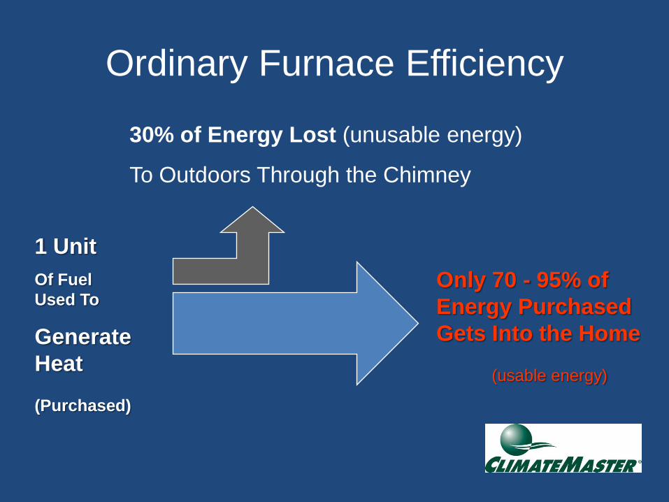
Ordinary Furnace Efficiency
30% of Energy Lost (unusable energy)
To Outdoors Through the Chimney
Only 70 - 95% of
Energy Purchased
Gets Into the Home
(usable energy)
1 Unit
Of Fuel
Used To
Generate
Heat
(Purchased)

Air Source Heat Pumpsa mixed blessing

Identified Issue – Winter Peaking
200
400
600
800
1000
1200
1400
1600
1800
01:00 07:00 13:00 19:00
MW
Local Time
Saturday July 24, 2004
200
400
600
800
1000
1200
1400
1600
1800
00:00 06:00 12:00 18:00 00:00
MW
Local Time
Monday January 24, 2005

Geothermal Heat Pump
The Superior Solution
• Renewable resource
• Highly energy efficient
• Available virtually everywhere
• Provides local employment


Geothermal Heat Pump Efficiency
1 unit of energy
from the grid
Plus:
3-5 units of “free” energy
from the earth
Yields:
4-6 units of energy
for the building
400-600% Efficient

Ground Source HP
A Renewable Resource

47% of the solar energy falling on our planet
is absorbed by the Earth’s surface…

Earth is a better Energy Source

Our Most Abundant Resource
• Greater than – Wind
– Photovoltaic
– Solar Thermal
– Coal
– Nuclear
– All fossil fuels combined

Geothermal Heat Pumps
are one of the Most Effective
and Deployable…
… producing the lowest carbon dioxide emissions, including all source effects, of all available space-conditioning technologies
(EPA, 1993)

Geothermal Heat Pump Efficiency
1 unit of energy
from the grid
Plus:
3-5 units of “free” energy
from the earth
Yields:
4-6 units of energy
for the building
400-600% Efficient


HVAC Energy Use ComparisonsReduces energy consumption by 50%
Conventional HVAC - HomeGeothermal HVAC - Home
Basic Geothermal Operation

A geothermal heat pump
circulates water through a
sealed underground piping loop
where it is naturally warmed (or
cooled) by the earth
…using Heat Pump Technology

The Earth is the Source of Heat in Winter…
Outdoor air
design temperature:
-5°F72°F
50°F
A geothermal heat pump transfers underground heat into the building to provide heating

…and an Efficient Place to Reject or Store Heat in Summer…
Outdoor air
design temperature:
95°F74°F
50°F
A geothermal heat pump transfers heat from the building into the ground to provide cooling

The Unlimited Energy Source
150 ft.or more
100 ft.40 ft.
Small Yard Space =
Large Heat Source
Lots of
Energy Available
40 BTUs Per Cubic Foot
Geothermal System Components
• Heat pump
• Ground loop
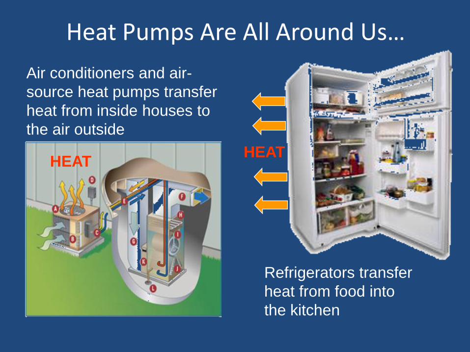
Heat Pumps Are All Around Us…
Air conditioners and air-
source heat pumps transfer
heat from inside houses to
the air outside
Refrigerators transfer
heat from food into
the kitchen
HEATHEAT

Ground Source Heat Pump
Advantages
• No defrost cycle – improved efficiency
• No outdoor enclosure required – less
expensive (non-split)
• Ground moderates EWT – improved
efficiency
• Quiet operation – no outdoor compressor

Heat Pump Components
• Compressor
• Refrigerant reversing valve
• Metering device – TXV
• Air heat exchanger – air coil
• Electrical Controls
• Fluid heat exchanger – ground loop (Coax)

Heating Cycle
Suction
Compressor
Discharge
Air
Coil Reversing
Valve
To
DHW Tank
To Loop
Source
COAXExpansion
Device Coax
HWG
Refrigeration Circuit
10/10/28/05vcbrev3
Option

Ground Loop DesignThe critical component
1. Requires specialized training
2. Installer needs to be certified
3. Installations should be inspected
Geothermal Loop Options
• Closed loops – Fluid is circulated within a
buried, continuous loop– Two types
• Vertical
• Horizontal
• Open Loops – Water is pumped and dumped
or re-injected– Two Types
Pond/Lake
Well systems

Various Applications

Geothermal Design Basics
• The ground loop

Equipment Sizing
• Once Building Loads are determined use our GeoDesigner Software to assist in the final design.
Since the equipment capacity is directly related to the EWT (Entering Water Temperature), the type of heat source/heat sink must be considered when sizing the equipment.

Ground Source (GSHP) / Closed Loop
• Benefits– Lower system maintenance
– No additional water requirements
• Hurdles– Requires more land space
– First cost

Closed LoopBasic Design Rules
• Special consideration should be given to
minimum distances from items such as Lot
Lines, Septic/Sewer, Water or other utilities
• Always check Local, County or State
Regulations for Permits, Documentation,
and Inspection Requirements
• Always prepare a site plan

Closed LoopBasic Design Rules – cont.
• Fluids will take the path of least resistance,
• Equal fluid flow between the loops must be maintained!– Keep all loop lengths within 5% of each other
– Use “reverse return” on the loop layout
– Use “reverse return” at the manifold

Closed LoopBasic Design Rules – cont.
• Remove all rocks away from the pipe loop
• Use wide turns
• Avoid kinking the pipes during back fill –(reverse return)
• Always perform a Hydrostatic Pressure Test BEFORE burying the piping system
Horizontal Loops
• Backhoe or trench excavation. (In areas with any rock - typically backhoe only)
• Loop Piping installed below frost line
– North - 4 - 6 ft max. depth
• 1 circuit and 3 gpm flow per ton
• Pipe per ton
– North - 600 to 1000 ft
– South - 700 to 1800 ft
Basic Design Rules

Horizontal Loop Types
2 fe
et
2 Pipe 1
circuit
4 Pipe 2
circuits
6 Pipe 3
circuits
2 feet 2 feet 2 feet
2 fe
et
2 fe
et
2 fe
et
Horizontal
Slinky
4ft pipe/1 ft
of trench
1 circuit
per trench
Flow Controller IOM Page Figure 14

Backhoe Horizontal Trenching Example


!Think Safety First!Not a good trench to work in, keep the dirt away
from trench to reduce danger of cave in
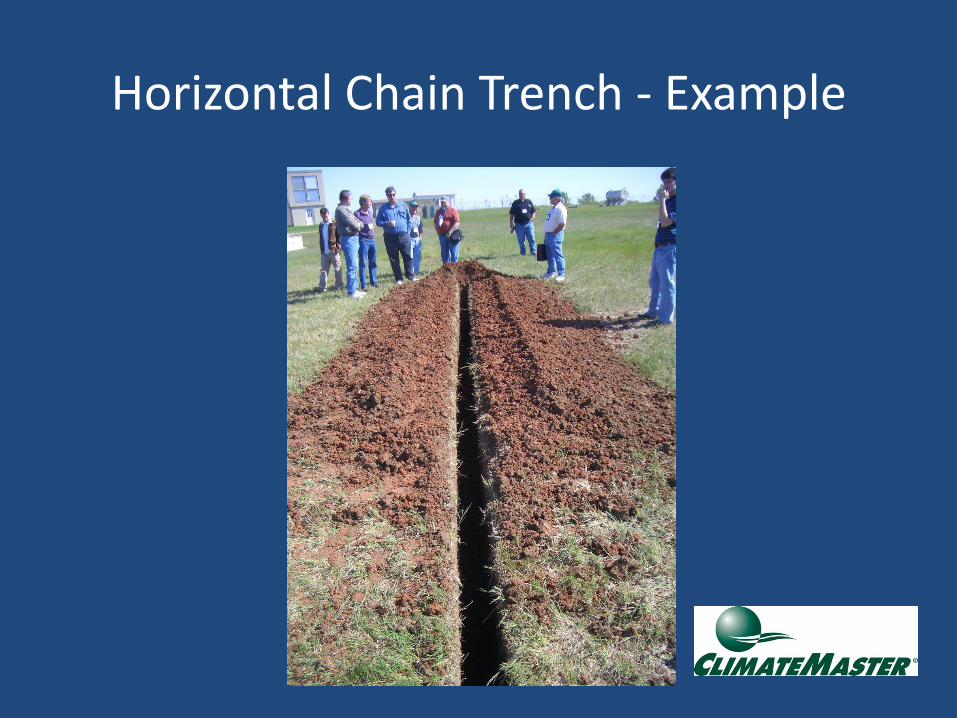
Horizontal Chain Trench - Example

Loop Circuit Header Manifold Reverse Return piping method
Flow Controller 2 IOM Figure 12 page 13
Design Reverse Return Reducing Header Manifold
lengths short to provide ( min.) 2 Feet Per Second (fps)
flow rates in all portions of the Header for good air
removal

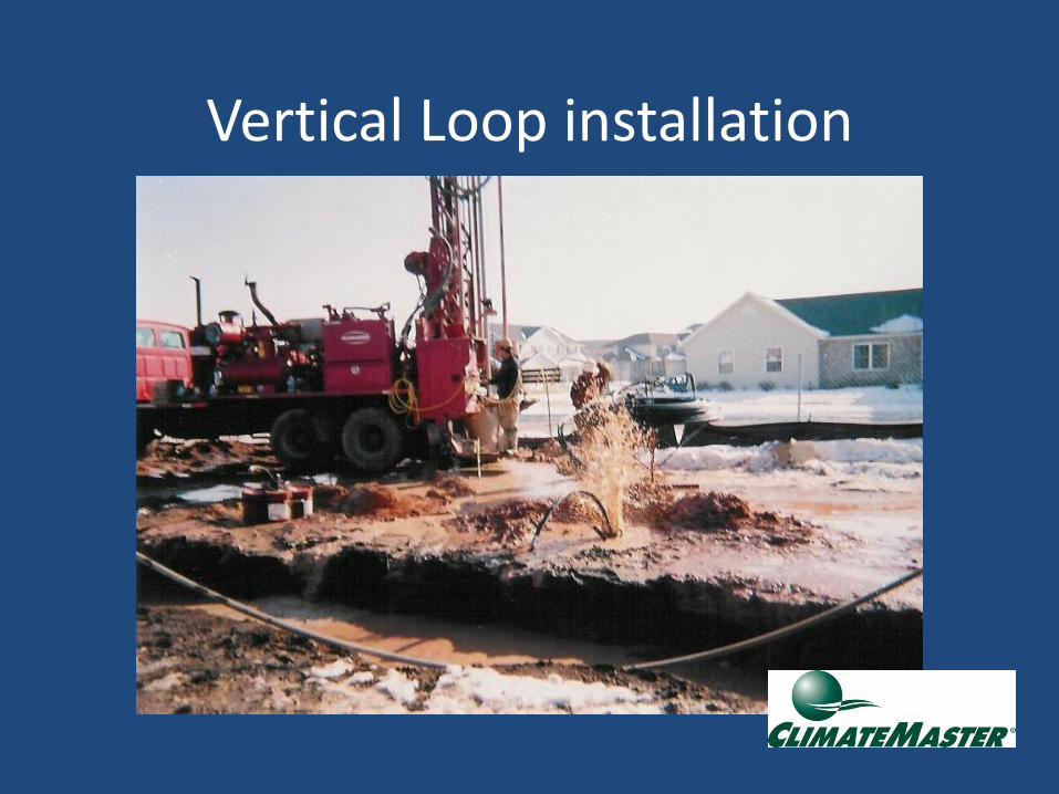
Vertical Loop installation

Vertical Loops
• One bore per ton• Bore hole spacing 10 ft minimum • One circuit at 3 GPM flow per ton for ¾”
and 1” circuits• U-Bend pipe sizes ¾” & 1” ID
– ASTM PE3408 HD Geothermal PE pipe
• Many states require bentonite grouting• Some locales restrict drilling• Bore Hole Depth (typical)
– North 150 -200ft/ton– South 250-300 ft/ton
Basic Rules

Vertical Loops
One Pair Series/Parallel One Pair
Avg
De
pth
Avg
De
pth
When Loops are
shallower than
one ton per loop
Both layouts provide
the same Total
amount of pipe
surface area …
Drilling conditions,
cost and equipment
may dictate what you
can do.

Vertical U-Bend with Grout

• Supply & Return
Piping exit straight out
from building
foundations-10 feet
min.
• Header Pit should be
10 feet min. from
building foundation
• Simple drawing shows
typical bore hole/circuit
layout.
• Actual Header Manifold
less than 24” long.
• Parallel circuit piping
3/4” & 1.0” dia. Pipe
sizes
Multiple Hole Vertical Loop

Pond Loops
• Least expensive ground loop
• Minimum 1/2 acre and 8 feet deep
• Pond should be within 300’ of structure
• In North - need ice cover for good operation
– Utilizes 39 deg F water temp (no aeration).
– Stagnate water body works best for heating
• Pipe Circuit length per ton
– North and South 300-500 ft/ton
Basic Design Rules

Pond/Lake Loop

Pond Loop Layout
Supply/Return Pipes
• Exit Perpendicular
to Foundation Wall
Typical Trench/Circuit layout
• Parallel Circuit Design
• 3/4” or 1” HD PE3408 pipe
• Extended Reverse Return
Header/Manifold

Antifreeze Materials
• Methanol
– least expensive and best performer, but toxic and flammable
• Propylene glycol
– non-toxic and expensive, but lowest heat transfer and unusable in cold loop.
Note: Your local Law and Codes may dictate approved fluid type

Methanol Safety
• Always mix outdoors
• Keep away from any open flames
• Avoid ingestion – highly toxic

Antifreeze containers –(Blue containers best way to identify Methanol
verse other fluids.)
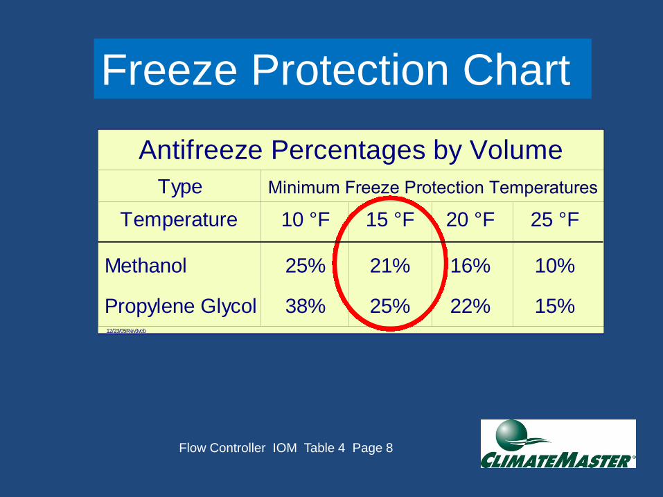
Freeze Protection Chart
Type
Methanol
Propylene Glycol
10 °F
25%
38%
15 °F
21%
25%
20 °F
16%
22%
25 °F
10%
15%12/23/05Rev3vcb
Antifreeze Percentages by Volume
Minimum Freeze Protection Temperatures
Temperature
Flow Controller IOM Table 4 Page 8
Freeze Protection Chart

Recommended Freeze Protection
IOM: D Page 14

Ground Water Open Loop Open Loop/Well Water
• Benefits
– Lowest first cost
– No land requirement
– Fast installation for retrofits
• Hurdles
– Requires clean water and maintenance
– Larger well pump/pressure tank
– Getting rid of water can be difficult
– Water Hammer

Loop Flushing
• Critical step
– Cleans any debris from the loop
– Flushes air from the system
– Mixes antifreeze solution in loop
– Pressurizes loop
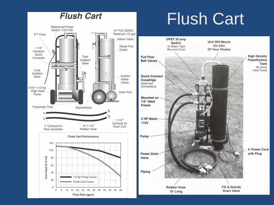
Flush Cart
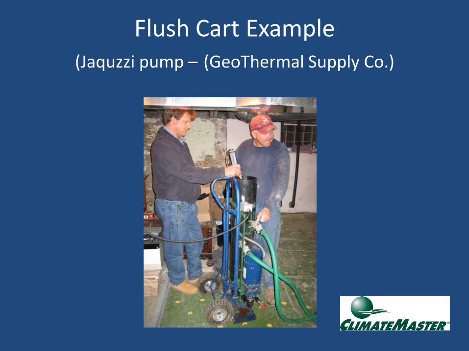
Flush Cart Example (Jaquzzi pump – (GeoThermal Supply Co.)

Equipment Sizing
• Building Heat Gain/Heat Loss is essential for any residential HVAC design, especially Geothermal Applications.
• Whole House methods are fine for the equipment sizing.
• Room by Room methods should always be used for Duct Sizing.

Comfort
1. Homes should be well sealed
2. More uniformly heat and cool than conventional HVAC systems
3. Systems are quieter

Equipment Applications
• Ducted Forced Air Systems
– The most common type of heating and cooling distribution system is the ducted forced air system, which delivers warm or cool air to the living space. Water-to-air packaged units or split system heat pumps are typically connected to a central duct layout, which distributes the conditioned air to the various zones.
– As in all forced air systems, properly designed and sealed ductwork is crucial to occupant comfort

Questions?