Embed Size (px)
Citation preview
Morrow Geotechnics Pty Ltd | ABN 42 605 892 126 PO Box 4069, Carlton NSW 2218
P: 0405 843 933 | E: [email protected]
Geot
echn
ical
Inve
stig
atio
n Re
port
RESIDENTIAL DEVELOPMENT
67 ARCADIA AVENUE, GYMEA BAY NSW
Prepared for:
YUCEL CETINAY
Reference: P2266_01
2 July 2021

P2266_01 2/07/2021 Page 2
Geo
tech
nica
l Inv
estig
atio
n –
67 A
rcad
ia A
venu
e, G
ymea
Bay
NSW
1 INTRODUCTION Morrow Geotechnics Pty Ltd has undertaken a Geotechnical Investigation to provide geotechnical advice and recommendations for the proposed development at 67 Arcadia Avenue, Gymea Bay NSW (the site).
1.1 Proposed Development Architectural drawings for the proposed development have been prepared by Plan Land dated October 2019. From the drawings provided, Morrow Geotechnics understands that the proposed development involves construction of a two storey residential structure at or near existing grade with a partial basement garage.
1.2 Purpose of the Investigation The purpose of the investigation is to provide geotechnical advice and recommendations addressing:
• Expected subsurface conditions;
• Allowable bearing pressure for slab and foundation design;
• Site classification for slab and foundation design; and
• Geotechnical construction considerations; J
1.3 Investigation Methods Fieldwork was undertaken on 28 June 2021. Work carried out as part of this investigation includes:
• Review of publicly available information from previous reports in the project area, published geological and soil mapping and government agency websites;
• Site walkover inspection by a Geotechnical Engineer to assess topographical features, condition of surrounding structures and site conditions;
• Dial Before You Dig (DBYD) services search of proposed borehole locations;
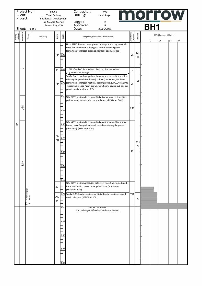
• Drilling of one borehole (BH1) using hand augers to refusal on sandstone bedrock at depths of 2.95 meters below ground level (mBGL) respectively. Borehole locations are shown on Figure 1 and the borehole logs are attached to this report;
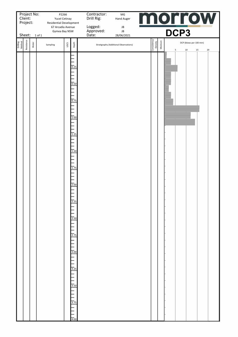
• Dynamic Cone Penetrometer (DCP) test adjacent to the borehole location, and at four other locations. DCP test were carried out to infer top of rock.
• Groundwater observations within boreholes during drilling.
2 DESKTOP REVIEW OF SITE CONDITIONS 2.1 Published Geological Mapping Information on regional sub-surface conditions, referenced from the Department of Mineral Resources Geological Map Wollongong – Port Hacking 1:100,000 Geological Series Sheet 9029 (DMR 1985), indicates that the site overlies Hawkesbury Sandstone, which typically comprises of medium to coarse-grained quartz sandstone, very minor shale and laminite lenses.

P2266_01 2/07/2021 Page 3
Geo
tech
nica
l Inv
estig
atio
n –
67 A
rcad
ia A
venu
e, G
ymea
Bay
NSW
2.2 Published Soil Landscapes The Soil Conservation Service of NSW Wollongong – Port Hacking 1:100,000 Soil Landscapes Series Sheet 9029 indicates that the colluvial landscape at the site likely comprises the Hawkesbury Landscape. This landscape type typically includes rugged, rolling to very steep hills on Hawkesbury Sandstone with slopes greater than 25 %. Soils are shallow (< 0.5 m) discontinuous lithosols / siliceous sands associated with rock outcrop; earthy sands and yellow earths. These soils are noted to present extreme soil erosion hazard, mass movement (rockfall hazard), steep slopes, rock outcrop, and shallow, stony, highly permeable soil.
3 OBSERVATIONS 3.1 Subsurface Conditions A walkover inspection to conduct geomorphological mapping of the site was undertaken. Local topography generally comprises a residual sandstone derived slope. The site slopes downwards towards the west.
The stratigraphy at the site is characterised by fill, colluvial and residual soil overlying sandstone bedrock. For the development of a site-specific geotechnical model, the observed stratigraphy has been divided into three geotechnical units. A summary of the subsurface conditions across the site, interpreted from the investigation results, is presented in Table 1. More detailed descriptions of subsurface conditions at the test locations are available in the borehole logs presented in Appendix A.
TABLE 1 SUMMARY OF INFERRED SUBSURFACE CONDITIONS
Unit Material
Approx. Depth Range of Unit 1 mBGL Comments
BH1
1 Fill / Colluvial Soil
0.0 to 0.95
Generally fine to medium grained SAND with some clay, silt, gravel, cobble, boulders and organic material present. Fill material within Unit 1 is inferred to be uncontrolled and poorly compacted.
2 Residual Soil 0.95 to 2.95 Generally medium to high plasticity silty clay with some ironstone gravel. Unit 2 grades into sandy clay at 2.7 mBGL.
3 Weathered Sandstone
2.95 +
Inferred from regional geology, borehole results and rock outcrop in the vicinity of the site to be distinctly weathered, very low to low strength sandstone. Rock strength will increase with excavation depth and medium strength sandstone is typically encountered within 2 m depth in the vicinity of the site.
Notes: 1 Depths shown are based on material observed within test locations and will vary across the site. 2 DCP2 to DCP5 were inferred to refuse on sandstone boulders within colluvial soil. Unit 3 at DCP locations should be confirmed by
a suitably qualified geotechnical engineer during construction inspections The depth to Unit 3 Sandstone will vary across the site due to slope conditions. Outcropping sandstone was observed on the site above the proposed building envelope.

P2266_01 2/07/2021 Page 4
Geo
tech
nica
l Inv
estig
atio
n –
67 A
rcad
ia A
venu
e, G
ymea
Bay
NSW
3.2 Groundwater Observations Seepage flow was observed within BH1 at approximately 2.9 m BGL during the investigation. Some seepage should be expected across the top of rock following rainfall.
4 GEOTECHNICAL RECOMMENDATIONS FOR DESIGN 4.1 Foundation Design It is not recommended that shallow footings or slabs found within Unit 1 or 2 material due to the potential for differential settlement caused by footings bridging between materials of varying stiffness. It is recommended that all footings are piered to Unit 3 sandstone to remove the risk of differential settlement across the building envelope.
Shallow footings and slabs on Unit 3 material should be designed in accordance with AS2870:2011 based on a Site Classification of ‘A.’ The site classification has been provided on the basis that the performance expectations set out in Appendix B of AS2870–2011 are acceptable and that future site maintenance will be undertaken in accordance with CSIRO BTF 18.
The parameters given in Table 2 may be used for the design of pad footings and bored piles. Morrow Geotechnics recommends that a Preliminary Geotechnical Strength Reduction Factor (GSRF) of 0.4 is used for the design of piles in accordance with AS 2159:2009 if no allowance is made for pile testing during construction. Should pile testing be nominated, the GSRF may be reviewed and a value of 0.55 to 0.65 may be expected.
Selection of footing types and founding depth will need to consider the risk of adverse differential ground movements within the foundation footprint and between high level and deeper footings. Unless an allowance for such movement is included in the design of the proposed development we recommend that all new structures found on natural materials with comparable end bearing capacities and elastic moduli.
Ultimate geotechnical strengths are provided for use in limit state design. Allowable bearing pressures are provide for serviceability checks. These values have been determined to limit settlements to an acceptable level for conventional building structures, typically less than 1% of the minimum footing dimension.
TABLE 2 PAD FOOTING AND PILE DESIGN PARAMETERS
Material Unit 1
Fill & Colluvial Soil
Unit 2 Residual Soil
Unit 3 Weathered Sandstone
Allowable Bearing Pressure (kPa) NA NA 700
Ultimate Vertical End Bearing Pressure (kPa)
NA NA 2100
Elastic Modulus (MPa) 5 12 75
Allowable Shaft Adhesion (kPa)
In Compression 0 10 70
In Tension 0 5 35
Susceptibility to Liquefaction during an Earthquake High Medium Low

P2266_01 2/07/2021 Page 5
Geo
tech
nica
l Inv
estig
atio
n –
67 A
rcad
ia A
venu
e, G
ymea
Bay
NSW
Notes:
1 Shaft adhesion values given assume there is intimate contact between the pile and foundation material. Design engineer to check both ‘piston’ pull-out and ‘cone’ pull-out mechanics in accordance with AS4678-2002 Earth Retaining Structures.
2 Susceptibility to liquefaction during an earthquake is based on the following definition: Low - Medium to very dense sands, stiff to hard clays, and rock Medium - Loose to medium dense sands, soft to firm clays, or uncontrolled fill below the water table High - Very loose sands or very soft clays below the water table
To adopt these parameters we have assumed that the bases of all footing excavations are cleaned of loose debris and water and inspected by a suitably qualified Geotechnical Engineer prior to footing construction to verify that ground conditions meet design assumptions. Where groundwater ingress is encountered during excavation, concrete is to be placed as soon as possible upon completion of excavation. Footing excavations should be pumped dry of water prior to pouring concrete, or alternatively a tremmie system could be used.
Sloped sites on sandstone have the potential to create detached sandstone “floaters”. Floaters may be resting on loose soil and can lead to footing movement if overloaded. A geotechnical engineer should check all footing locations to confirm that stable bedrock has been achieved.
4.2 AS1170 Earthquake Site Risk Classification Assessment of the material encountered during the investigation in accordance with the guidelines provided in AS1170.4-2007 indicates an earthquake subsoil class of Class Be – Rock for the site.
4.3 Excavations Minor excavations up to a depth of approximately 1.5 m may be required for the development. Temporary batter slopes of 1H:1V will be possible for Unit 1 and 2 material provided that surface water is diverted away from the batter faces and batter heights are kept to less than 3 m. Permanent batters of 2H:1V may be employed for Unit 1 and 2 material. Permanent batters will require surface protection or revegetation to prevent erosion and slaking. Unit 3 Weathered Sandstone may be cut vertically without support provided that geotechnical inspections are undertaken during construction to ensure that isolated blocks and wedges are not present within the rock cutting. If blocks and wedges are present isolated spot bolting or shotcreting may be required as support.
Where excavations extend beneath the zone of influence of nearby structures, services or pavements, or where site constraints such as site boundaries do not allow the construction of temporary batters, excavation retention will be required. For design of cantilevered shoring systems a triangular pressure distribution may be employed using the parameters presented in Table 3. For design of rigid anchored or braced walls such as top-down construction, a trapezoidal earth pressure distribution should be used with a maximum pressure of 0.65.Ka.γ.H (kPa), where ‘H’ is the effective vertical height of the wall in metres.

P2266_01 2/07/2021 Page 6
Geo
tech
nica
l Inv
estig
atio
n –
67 A
rcad
ia A
venu
e, G
ymea
Bay
NSW
TABLE 3 EARTH PRESSURE PARAMETERS
Material Unit 1 Fill & Colluvial Soil
Unit 2 Residual Soil
Unit 3 Weathered Sandstone
Bulk Unit Weight (kN/m3) 16 17 23
Eart
h Pr
essu
re
Coef
ficie
nts
At rest, Ko
0.55 0.50 0.25
Passive, Kp 2.66 3.00 4.00
Active, Ka 0.38 0.33 0.15
Notes: 1 Unit Weight is based on visual assessment only, order of accuracy is approximately ±10%. 2 Earth pressures are provided on the assumption that the ground behind the retaining wall is flat and drained.
4.4 Soil and Rock Excavatability The expected ability of equipment to excavate the soil and rock encountered at the site is summarised in Table 4. This assessment is based on available site investigation data and guidance on the assessment of excavatability of rock by Pettifer and Fookes (1994). The presence of medium to high strength bands in lower strength rock and the discontinuity spacing may influence the excavatability of the rock mass.
TABLE 4 SOIL AND ROCK EXCAVATABILITY
Unit Material Excavatability
1 Fill Easy digging by 20t Excavator
2 Natural Soils Easy digging by 20t Excavator
3 Weathered Sandstone Hydraulic hammering will be required where medium to high strength
sandstone is encountered within the excavation profile.
The excavation methodology may also be affected by the following factors:
• Scale and geometry of the excavation;
• Availability of suitable construction equipment;
• Potential reuse of material on site; and
• Acceptable excavation methods, noise, ground vibration and other environmental criteria.
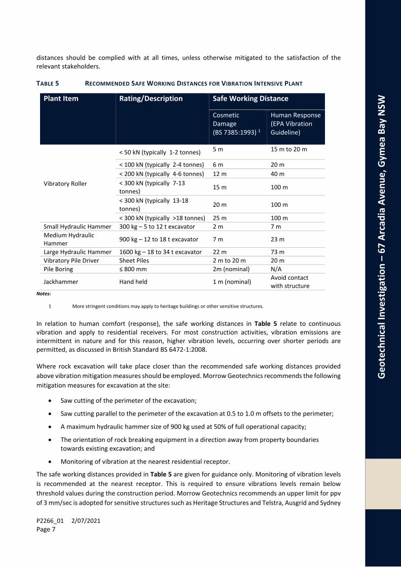
4.5 Excavation Vibration Considerations As a guide, safe working distances for typical items of vibration intensive plant are listed in Table 5. The safe working distances are quoted for both “cosmetic” damage (refer British Standard BS 7385:1993) and human comfort (refer NSW Environmental Protection Agency Vibration Guideline).The safe working
P2266_01 2/07/2021 Page 7
Geo
tech
nica
l Inv
estig
atio
n –
67 A
rcad
ia A
venu
e, G
ymea
Bay
NSW
distances should be complied with at all times, unless otherwise mitigated to the satisfaction of the relevant stakeholders.
TABLE 5 RECOMMENDED SAFE WORKING DISTANCES FOR VIBRATION INTENSIVE PLANT
Plant Item Rating/Description Safe Working Distance
Cosmetic Damage (BS 7385:1993) 1
Human Response (EPA Vibration Guideline)
Vibratory Roller
< 50 kN (typically 1-2 tonnes) 5 m 15 m to 20 m
< 100 kN (typically 2-4 tonnes) 6 m 20 m < 200 kN (typically 4-6 tonnes) 12 m 40 m < 300 kN (typically 7-13 tonnes) 15 m 100 m
< 300 kN (typically 13-18 tonnes) 20 m 100 m
< 300 kN (typically >18 tonnes) 25 m 100 m Small Hydraulic Hammer 300 kg – 5 to 12 t excavator 2 m 7 m Medium Hydraulic Hammer 900 kg – 12 to 18 t excavator 7 m 23 m
Large Hydraulic Hammer 1600 kg – 18 to 34 t excavator 22 m 73 m Vibratory Pile Driver Sheet Piles 2 m to 20 m 20 m Pile Boring ≤ 800 mm 2m (nominal) N/A
Jackhammer Hand held 1 m (nominal) Avoid contact with structure
Notes:
1 More stringent conditions may apply to heritage buildings or other sensitive structures.
In relation to human comfort (response), the safe working distances in Table 5 relate to continuous vibration and apply to residential receivers. For most construction activities, vibration emissions are intermittent in nature and for this reason, higher vibration levels, occurring over shorter periods are permitted, as discussed in British Standard BS 6472-1:2008.
Where rock excavation will take place closer than the recommended safe working distances provided above vibration mitigation measures should be employed. Morrow Geotechnics recommends the following mitigation measures for excavation at the site:
• Saw cutting of the perimeter of the excavation;
• Saw cutting parallel to the perimeter of the excavation at 0.5 to 1.0 m offsets to the perimeter;
• A maximum hydraulic hammer size of 900 kg used at 50% of full operational capacity;
• The orientation of rock breaking equipment in a direction away from property boundaries towards existing excavation; and
• Monitoring of vibration at the nearest residential receptor.
The safe working distances provided in Table 5 are given for guidance only. Monitoring of vibration levels is recommended at the nearest receptor. This is required to ensure vibrations levels remain below threshold values during the construction period. Morrow Geotechnics recommends an upper limit for ppv of 3 mm/sec is adopted for sensitive structures such as Heritage Structures and Telstra, Ausgrid and Sydney

P2266_01 2/07/2021 Page 8
Geo
tech
nica
l Inv
estig
atio
n –
67 A
rcad
ia A
venu
e, G
ymea
Bay
NSW
Water mains (or as recommended by utility owner), 10 mm/sec is adopted for residential buildings and 20 mm/sec is adopted for commercial and industrial buildings or reinforced concrete structures. Should vibrations exceed set limits, we recommend the following:
• Cease excavation works and notify the Geotechnical Engineer immediately; and
• Develop an alternative excavation plan in conjunction with the Geotechnical Engineer.
4.6 Slope Risk Assessment A Slope Risk Assessment has been carried out for the site in accordance with Australian Geomechanics Society 2007 Guidelines. This assessment is based on surface conditions observed during the inspection and subsurface conditions inferred from mapped regional geology. These guidelines allow the stability of the slope/ structure to be assessed in terms of risk to property and loss of life based on the physical features of the slope and the proposed development. Typical risk indicators of potential slope instability are:
• high slope angles; • adverse dipping of rock joints and bedding in conjunction with dip direction of the rock joints; • high degree of weathering; and • signs of previous slope movements.
4.6.1 Potential Slope Hazards Morrow Geotechnics considers that structures and people at the site may be impacted by the following potential hazards:
Hazard 1: Global failure of cliff line and mobilisation of large sandstone blocks (maximum block dimensions 3 m x 3 m x 3 m
Hazard 2: Soil creep of surficial material across sandstone
Slope hazards have been assessed against a structure built in accordance with the geotechnical recommendations listed above.
4.6.2 Assessed Risk Level for Property Damage The risk zoning using property loss criteria in accordance with AGS 2007c is presented in Table 6.
TABLE 6 SEMI-QUANTITATIVE ASSESSMENT FOR PROPERTY DAMAGE
Hazard Likelihood
(Indicative value of annual probability)
Consequence (Indicative Value)
Assessed Risk Level
Hazard 1 Barely Credible
(1 x 10⁻⁶) Major (60%)
Very Low

P2266_01 2/07/2021 Page 9
Geo
tech
nica
l Inv
estig
atio
n –
67 A
rcad
ia A
venu
e, G
ymea
Bay
NSW
Hazard Likelihood
(Indicative value of annual probability)
Consequence (Indicative Value)
Assessed Risk Level
Hazard 2 Possible (1 x 10⁻³)
Insignificant (0.5%)
Low
The risk zoning using property loss criteria in accordance with AGS 2007c is assessed to be Low.
3.6.3 Assessed Risk Level for Loss of Life The risk zoning using loss of life criteria in accordance with AGS 2007c is presented in Table 7
TABLE 7 QUANTITATIVE ASSESSMENT FOR LOSS OF LIFE
Hazard Annual
Probability P(H)
Probability of Spatial Impact
PIS:H)
Temporal Spatial
Probability PIS:H)
Vulnerability of Individual
V(D:T)
Annual Probability of
Loss of Life R(LoL)
Hazard 1 1 x 10⁻⁶ 1.0 1.0 0.1 1 x 10⁻⁷
Hazard 2 1 x 10⁻³ 0.1 1.0 1 x 10⁻² 1 x 10⁻⁶
The assessed maximum risk to loss of life according to the quantitative risk assessment is 1 x 10⁻⁶.
3.6.4 Pre-Development Risk Levels
The qualitative risk assessment indicates the site to have a Low Risk of damage to property as a result of the potential hazards identified. AGS Landslide Risk Management Concepts and Guidelines state that a Low assessed risk to property is “usually acceptable to regulators.” The AGS stipulates that the client, owner or, if appropriate, the regulator must carry out their own assessment to determine whether the low risk to property and damage is acceptable or tolerable.
The annual probability of loss of life for the person most at risk as a result of slope instability impacting the site is calculated to be less than 1 x 10⁻⁶. The AGS Landslide Risk Management Concepts and Guidelines provide guidance on tolerable and acceptable loss of life risk for the person most at risk, indicating that a risk level of 1 x 10⁻⁴ is typically considered tolerable for existing slopes while 1 x 10⁻⁵ is typically acceptable for proposed developments. The AGS stipulates that the client, owner or, if appropriate, the regulator must carry out their own assessment to determine whether the low risk to property and damage is acceptable or tolerable.

P2266_01 2/07/2021 Page 10
Geo
tech
nica
l Inv
estig
atio
n –
67 A
rcad
ia A
venu
e, G
ymea
Bay
NSW
3.6.5 Recommended Construction Procedures to Minimise Identified Risks
Morrow Geotechnics recommends the following measures are undertaken during construction in order to minimise the risks identified as part of the slope risk assessment:
• Any excavations greater than 1.0 m depth opened for the installation of footings or services should be inspected by an experienced geotechnical engineer and adverse features within the rock mass, including but not limited to inclined joints, decomposed seams, wedges, blocks or highly fractured zones, should be identified and mapped. Stabilisation measures should be proposed by the geotechnical engineer and undertaken prior to the excavation proceeding.
• All proposed footings should be piered to stable sandstone and inspected by a geotechnical engineer during construction.
• Surface water flow should be directed away from construction areas and the crests of retaining walls during the works.
• Drainage must be maintained behind any retaining walls and should be inspected following construction to ensure that it remains clear.
3.6.6 Anticipated Risk Level Post Development Should the construction procedures outlined above be complied with, Morrow Geotechnics anticipates that the assessed risk levels will remain unchanged as a result of the proposed development. The anticipated post development risk levels are:
• Low for risk of damage to property; and • 1 x 10⁻⁶ for risk of loss of life.
This assessment is contingent upon all advice and recommendations given by geotechnical professionals prior to and during the construction being implemented.
5 RECOMMENDATIONS FOR FURTHER GEOTECHNICAL SERVICES Further geotechnical inspections should be carried out during construction to confirm the geotechnical and hydrogeological model. These should include:
• All excavated material transported off site should be classified in accordance with NSW EPA 2014 - Waste Classification Guideline Part 1; Classifying Waste.
• A suitably qualified geotechnical engineer is to assess the condition of exposed material at foundation or subgrade level to assess the ability of the prepared surface to act as a foundation or as a subgrade.

P2266_01 2/07/2021 Page 11
Geo
tech
nica
l Inv
estig
atio
n –
67 A
rcad
ia A
venu
e, G
ymea
Bay
NSW
6 STATEMENT OF LIMITATIONS The adopted investigation was limited by the agreed scope of the investigation. Further geotechnical inspections should be carried out during construction to confirm both the geotechnical model and the design parameters provided in this report.
Your attention is drawn to the document “Important Information”, which is included in Appendix B of this report. The statements presented in this document are intended to advise you of what your realistic expectations of this report should be. The document is not intended to reduce the level of responsibility accepted by Morrow Geotechnics, but rather to ensure that all parties who may rely on this report are aware of the responsibilities each assumes in so doing.
7 REFERENCES AS1726:1993, Geotechnical Site Investigations, Standards Australia.
AS2159:2009, Piling – Design and Installation, Standards Australia.
AS2870:2011, Residential Slabs and Footings, Standards Australia.
AS3798:2007, Guidelines on Earthworks for Commercial and Residential Developments, Standards Australia.
Chapman, G.A. and Murphy, C.L. (1989), Soil Landscapes of the Sydney 1:100000 sheet. Soil Conservation Services of NSW, Sydney.
NSW Department of Finance and Service, Spatial Information Viewer, maps.six.nsw.gov.au.
NSW Department of Mineral Resources (1983) Sydney 1:100,000 Geological Series Sheet 9130 (Edition 1). Geological Survey of New South Wales, Department of Mineral Resources.
Pells (2004) Substance and Mass Properties for the Design of Engineering Structures in the Hawkesbury Sandstone, Australian Geomechanics Journal, Vol 39 No 3
8 CLOSURE Please do not hesitate to contact Morrow Geotechnics if you have any questions about the contents of this report.

P2266_01 2/07/2021 Page 12
Geo
tech
nica
l Inv
estig
atio
n –
67 A
rcad
ia A
venu
e, G
ymea
Bay
NSW
For and on behalf of Morrow Geotechnics Pty Ltd,
James Brooker
Geotechnical Engineer
Alan Morrow
Principal Geotechnical Engineer

Project: P2266
Figure:
1Yucel Cetinay
67 Arcadia Avenue, Gymea Bay NSWGeotechnical InvestigationBorehole Location Plan
PO Box 4069, Carlton NSW 2218P: 0405 843 933 | E: [email protected] Scale
DateApprovedDrawn JB
AM2/07/2021
NTS
Plan Source: Boxall Surveyors Pty Ltd, Plan Showing Partial Site Detail and Levels, Dwg. 11224‐002, 11/06/2021
BH1
Sandstone Outcrop
DCP5DCP2DCP3DCP4
A A'

Project: P2266
Figure:
2Yucel Cetinay
67 Arcadia Avenue, Gymea Bay NSWGeotechnical Investigation
Site Section A‐A'PO Box 4069, Carlton NSW 2218
P: 0405 843 933 | E: [email protected] ScaleDate
ApprovedDrawn JB
2/07/2021NTS
Appe
ndix
A
BOREHOLE LOGS AND EXPLANATORY NOTES
5 10 15 20
MGHand Auger
JB
Yucel CetinayResidential DevelopmentProject:
Client:
67 Arcadia AvenueGymea Bay NSW
Contractor:Drill Rig:
Logged:Approved:
Project No: P2266
Date:Sheet: 1 of 1
Drilling
Metho
d
Resistance
Water
Sampling
USCS
0.50
Depth
FILL ‐ SAND, fine to coarse grained, orange, trace clay, trace silt, trace fine to medium sub‐angular to sub‐rounded gravel (sandstone), charcoal, organics, rootlets, poorly graded
FILL ‐ Sandy CLAY, medium plasticity, fine to medium grained sand, orange
4.00
0.25
2.50
2.75
3.00
3.25
3.50
3.75
1.00
1.25
1.50
1.75
2.00
2.25
0.75
28/06/2021
DCP (blows per 100 mm)
Consistency/
Density
Moisture
Stratigraphy (Additional Observations)
JB
BH1
End BH1 at 2.95 mPractical Auger Refusal on Sandstone Bedrock
HA
LL‐M
M‐H
SP
CI‐CH
CI
CL‐CI
CI
SP
Minor seepage
2.9 m
Silty CLAY, medium to high plasticity, brown‐orange, trace fine grained sand, rootlets, decomposed roots, (RESIDUAL SOIL)
Silty CLAY, medium to high plasticity, pale grey mottled orange‐brown, trace fine grained sand, trace fine sub‐angular gravel (ironstone), (RESIDUAL SOIL)
Silty CLAY, medium plasticity, pale grey, trace fine grained sand, trace medium to coarse sub‐angular gravel (ironstone), (RESIDUAL SOIL)
Sandy CLAY, low to medium plasticity, fine to medium grained sand, pale grey, (RESIDUAL SOIL)
M‐W
SAND, fine to medium grained, brown‐grey, trace silt, trace fine sub‐angular gravel (sandstone), cobble (sandstone), boulders (sandstone), charcoal, rootlets, poorly graded, (COLLUVIAL SOIL)‐ becoming orange / grey‐brown, with fine to coarse sub‐angular gravel (sandstone) from 0.7 m
VSt
VL
‐
MVL
F‐St
St
M<PL
D

Project: Residential Development67 Arcadia Avenue Logged: JB
Project No: P2266 Contractor: MGClient: Yucel Cetinay Drill Rig: Hand Auger
Drilling
Metho
d
Resistance
Water
Sampling
USCS
Depth
DCP2Gymea Bay NSW Approved: JBDate: 28/06/2021Sheet: 1 of 1
Stratigraphy (Additional Observations)
Consisten
cy/
Density
Moisture
DCP (blows per 100 mm)
5 10 15 20
0.25
0.50
0.75
1.00
1.25
1.50
1.75
2.00
2.25
2.50
2.75
3.00
3.25
3.50
3.75
4.00
Client: Yucel Cetinay Drill Rig: Hand AugerProject: Residential Development
67 Arcadia Avenue Logged: JB
Project No: P2266 Contractor: MGDrilling
Metho
d
Resistance
Water
Sampling
USCS
Depth
DCP3Gymea Bay NSW Approved: JBSheet: 1 of 1 Date: 28/06/2021
Stratigraphy (Additional Observations)
Consisten
cy/
Density
Moisture
DCP (blows per 100 mm)
5 10 15 20
0.25
0.50
0.75
1.00
1.25
1.50
1.75
2.00
2.25
2.50
2.75
3.00
3.25
3.50
3.75
4.00

Client: Yucel Cetinay Drill Rig: Hand AugerProject: Residential Development
67 Arcadia Avenue Logged: JB
Project No: P2266 Contractor: MGDrilling
Metho
d
Resistance
Water
Sampling
USCS
Depth
DCP4Gymea Bay NSW Approved: JBSheet: 1 of 1 Date: 28/06/2021
Stratigraphy (Additional Observations)
Consisten
cy/
Density
Moisture
DCP (blows per 100 mm)
5 10 15 20
0.25
0.50
0.75
1.00
1.25
1.50
1.75
2.00
2.25
2.50
2.75
3.00
3.25
3.50
3.75
4.00

Client: Yucel Cetinay Drill Rig: Hand AugerProject: Residential Development
67 Arcadia Avenue Logged: JB
Project No: P2266 Contractor: MGDrilling
Metho
d
Resistance
Water
Sampling
USCS
Depth
DCP5Gymea Bay NSW Approved: JBSheet: 1 of 1 Date: 28/06/2021
Stratigraphy (Additional Observations)
Consisten
cy/
Density
Moisture
DCP (blows per 100 mm)
5 10 15 20
0.25
0.50
0.75
1.00
1.25
1.50
1.75
2.00
2.25
2.50
2.75
3.00
3.25
3.50
3.75
4.00
Soil
and
Rock
Log
ging
Exp
lana
tory
Not
es
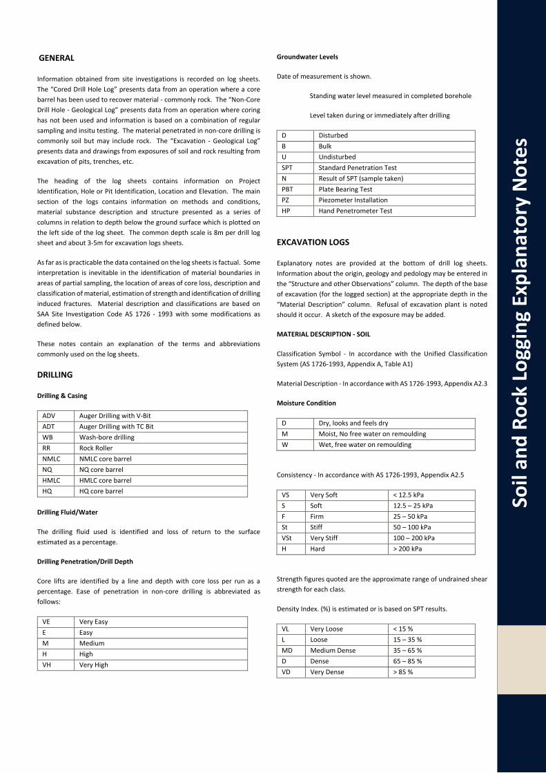
GENERAL
Information obtained from site investigations is recorded on log sheets. The “Cored Drill Hole Log” presents data from an operation where a core barrel has been used to recover material - commonly rock. The “Non-Core Drill Hole - Geological Log” presents data from an operation where coring has not been used and information is based on a combination of regular sampling and insitu testing. The material penetrated in non-core drilling is commonly soil but may include rock. The “Excavation - Geological Log” presents data and drawings from exposures of soil and rock resulting from excavation of pits, trenches, etc.
The heading of the log sheets contains information on Project Identification, Hole or Pit Identification, Location and Elevation. The main section of the logs contains information on methods and conditions, material substance description and structure presented as a series of columns in relation to depth below the ground surface which is plotted on the left side of the log sheet. The common depth scale is 8m per drill log sheet and about 3-5m for excavation logs sheets.
As far as is practicable the data contained on the log sheets is factual. Some interpretation is inevitable in the identification of material boundaries in areas of partial sampling, the location of areas of core loss, description and classification of material, estimation of strength and identification of drilling induced fractures. Material description and classifications are based on SAA Site Investigation Code AS 1726 - 1993 with some modifications as defined below.
These notes contain an explanation of the terms and abbreviations commonly used on the log sheets.
DRILLING
Drilling & Casing
ADV Auger Drilling with V-Bit ADT Auger Drilling with TC Bit WB Wash-bore drilling RR Rock Roller NMLC NMLC core barrel NQ NQ core barrel HMLC HMLC core barrel HQ HQ core barrel
Drilling Fluid/Water
The drilling fluid used is identified and loss of return to the surface estimated as a percentage.
Drilling Penetration/Drill Depth
Core lifts are identified by a line and depth with core loss per run as a percentage. Ease of penetration in non-core drilling is abbreviated as follows:
VE Very Easy E Easy M Medium H High VH Very High
Groundwater Levels
Date of measurement is shown.
Standing water level measured in completed borehole
Level taken during or immediately after drilling
D Disturbed B Bulk U Undisturbed SPT Standard Penetration Test N Result of SPT (sample taken) PBT Plate Bearing Test PZ Piezometer Installation HP Hand Penetrometer Test
EXCAVATION LOGS
Explanatory notes are provided at the bottom of drill log sheets. Information about the origin, geology and pedology may be entered in the “Structure and other Observations” column. The depth of the base of excavation (for the logged section) at the appropriate depth in the “Material Description” column. Refusal of excavation plant is noted should it occur. A sketch of the exposure may be added.
MATERIAL DESCRIPTION - SOIL
Classification Symbol - In accordance with the Unified Classification System (AS 1726-1993, Appendix A, Table A1)
Material Description - In accordance with AS 1726-1993, Appendix A2.3
Moisture Condition
D Dry, looks and feels dry M Moist, No free water on remoulding W Wet, free water on remoulding
Consistency - In accordance with AS 1726-1993, Appendix A2.5
VS Very Soft < 12.5 kPa S Soft 12.5 – 25 kPa F Firm 25 – 50 kPa St Stiff 50 – 100 kPa VSt Very Stiff 100 – 200 kPa H Hard > 200 kPa
Strength figures quoted are the approximate range of undrained shear strength for each class.
Density Index. (%) is estimated or is based on SPT results.
VL Very Loose < 15 % L Loose 15 – 35 % MD Medium Dense 35 – 65 % D Dense 65 – 85 % VD Very Dense > 85 %

Soil
and
Rock
Log
ging
Exp
lana
tory
Not
es
MATERIAL DESCRIPTION -ROCK
Material Description
Identification of rock type, composition and texture based on visual features in accordance with AS 1726-1993, Appendix A3.1-A3.3 and Tables A6a, A6b and A7.
Core Loss
Is shown at the bottom of the run unless otherwise indicated.
Bedding
Thinly Laminated < 6 mm Laminated 6 - 20 Very Thinly Bedded 20 - 60 Thinly Bedded 60 - 200 Medium Bedded 200 – 600 Thickly Bedded 600 – 2000 Very Thickly Bedded > 2000
Weathering - No distinction is made between weathering and alteration. Weathering classification assists in identification but does not imply engineering properties.
Fresh (F) Rock substance unaffected by weathering Slightly Weathered (SW)
Rock substance partly stained or discoloured. Colour and texture of fresh rock recognisable.
Moderately Weathered (MW)
Staining or discolouration extends throughout rock substance. Fresh rock colour not recognisable.
Highly Weathered (HW)
Stained or discoloured throughout. Signs of chemical or physical alteration. Rock texture retained.
Extremely Weathered (EW)
Rock texture evident but material has soil properties and can be remoulded.
Strength - The following terms are used to described rock strength:
Rock Strength Class
Abbreviation Point Load Strength Index, Is(50) (MPa)
Extremely Low EL < 0.03 Very Low VL 0.03 to 0.1 Low L 0.1 to 0.3 Medium M 0.3 to 1 High H 1 to 3 Very High VH 3 to 10 Extremely High EH ≥ 10
Strengths are estimated and where possible supported by Point Load Index Testing of representative samples. Test results are plotted on the graphical estimated strength by using:
° Diametral Point Load Test
Axial Point Load Test
Where the estimated strength log covers more than one range it indicates the rock strength varies between the limits shown.
MATERIALS STRUCTURE/FRACTURES
ROCK
Natural Fracture Spacing - A plot of average fracture spacing excluding defects known or suspected to be due to drilling, core boxing or testing. Closed or cemented joints, drilling breaks and handling breaks are not included in the Natural Fracture Spacing.
Visual Log - A diagrammatic plot of defects showing type, spacing and orientation in relation to core axis.
Defects Defects open in-situ or clay sealed Defects closed in-situ Breaks through rock substance
Additional Data - Description of individual defects by type, orientation, in-filling, shape and roughness in accordance with AS 1726-1993, Appendix A Table A10, notes and Figure A2.
Orientation - angle relative to the plane normal to the core axis.
Type BP JT SM FZ SZ VN FL CL DL HB DB
Bedding Parting Joint Seam Fracture Zone Shear Zone Vein Foliation Cleavage Drill Lift Handling Break Drilling Break
Infilling CN X Clay KT CA Fe Qz MS MU
Clean Carbonaceous Clay Chlorite Calcite Iron Oxide Quartz Secondary Mineral Unidentified Mineral
Shape PR CU UN ST IR DIS
Planar Curved Undulose Stepped Irregular Discontinuous
Rougness POL SL S RF VR
Polished Slickensided Smooth Rough Very Rough
SOIL
Structures - Fissuring and other defects are described in accordance with AS 1726-1993, Appendix A2.6, using the terminology for rock defects.
Origin - Where practicable an assessment is provided of the probable origin of the soil, eg fill, topsoil, alluvium, colluvium, residual soil.

Appe
ndix
B
IMPORTANT INFORMATION

Impo
rtant
Info
rmat
ion This Document has been provided by Morrow Geotechnics Pty Ltd subject to the following limitations:
This Document has been prepared for the particular purpose outlined in Morrow Geotechnics’ proposal and no responsibility is accepted for the use of this Document, in whole or in part, in other contexts or for any other purpose.
The scope and the period of Morrow Geotechnics’ Services are as described in Morrow Geotechnics’ proposal, and are subject to restrictions and limitations. Morrow Geotechnics did not perform a complete assessment of all possible conditions or circumstances that may exist at the site referenced in the Document. The scope of services may have been limited by such factors as time, budget, site access or other site conditions. If a service is not expressly indicated, do not assume it has been provided. If a matter is not addressed, do not assume that any determination has been made by Morrow Geotechnics in regards to it. Any advice given within this document is limited to geotechnical considerations only. Other constraints particular to the project, including but not limited to architectural, environment, heritage and planning matters may apply and should be assessed independently of this advice.
Conditions may exist which were undetectable given the limited nature of the enquiry Morrow Geotechnics was retained to undertake with respect to the site. Variations in conditions may occur between investigatory locations, and there may be special conditions pertaining to the site which have not been revealed by the investigation and which have not therefore been taken into account in the Document. Accordingly, additional studies and actions may be required. No geotechnical investigation can provide a full understanding of all possible subsurface details and anomalies at a site.
In addition, it is recognised that the passage of time affects the information and assessment provided in this Document. Morrow Geotechnics’ opinions are based upon information that existed at the time of the production of the Document. It is understood that the Services provided allowed Morrow Geotechnics to form no more than an opinion of the actual conditions of the site at the time the site was visited and cannot be used to assess the effect of any subsequent changes in the quality of the site, or its surroundings, or any laws or regulations.
Any assessments made in this Document are based on the conditions indicated from published sources and the investigation described. No warranty is included, either express or implied, that the actual conditions will conform exactly to the assessments contained in this Document.
Where data supplied by the client or other external sources, including previous site investigation data, have been used, it has been assumed that the information is correct unless otherwise stated. No responsibility is accepted by Morrow Geotechnics for incomplete or inaccurate data supplied by others.
Where ground conditions encountered at the site differ significantly from those anticipated in the report, either due to natural variability of subsurface conditions or construction activities, it is a condition of the report that Morrow Geotechnics be notified of any variations and be provided with an opportunity to review the recommendations of this report.
This Document is provided for sole use by the Client and is confidential to it and its professional advisers. No responsibility whatsoever for the contents of this Document will be accepted to any person other than the Client. Any use which a third party makes of this Document, or any reliance on or decisions to be made based on it, is the responsibility of such third parties. Morrow Geotechnics accepts no responsibility for damages, if any, suffered by any third party as a result of decisions made or actions based on this Document.