Embed Size (px)
Citation preview

designers by natureABN 280 979 293 72Registration Number DP-AD 1430
Address: 152 TIMOR STREET WARRNAMBOOL VICTORIA 3280 AUSTRALIAP +0499 058 417 | E [email protected] |W www.designersbynature.com.au
General NotesThe Builder shall check all dimensions and levels on site prior to construction.Notify any errors, discrepancies or omissions to the designer.Drawings shall not be used for construction purposes until issued for construction.Do not scale drawings.All boundaries and contours subject to survey
GRAY RESIDENCE
20-3
7G
RAY
RESI
DENC
EC
D-0
6 - W
IP
Work in Progress
Work in Progress
REV ID CH ID CHANGE DATE REV ID CH ID CHANGE DATE
CD-06 -WIP Work in Progress
Work in Progress
REV ID ISSUED FOR DATE NAME
CD-06 -WIP RFI - BUILDING PERMIT Work in
Progress
PLO
T D
ATE:
DR
AWN
BY
:
GRAY RESIDENCE
1656 Bridgewater Road, CapeBridgewater
Rod + Wendy
CONSTRUCTION DOCUMENTSDRAWING LISTS AND
NOTES
PROJECT NAME :
DR
AWIN
G T
ITLE
:
CLIENT :
SITE :
20-3
7
SHEE
T N
O.
1
REV
ISIO
N N
O.
CD-06 -WIP
DEAN
25/03/2021PRINCIPAL DRAWING SCALE
1:100 (unless noted) @ A1IN METRES
0 1 2 3
GRA
Y RE
SIDE
NCE
CD
-06
- WIP
designers by natureABN 280 979 293 72Registration Number DP-AD 1430
Address: 152 TIMOR STREET WARRNAMBOOL VICTORIA 3280 AUSTRALIAP +0499 058 417 | E [email protected] |W www.designersbynature.com.au
General NotesThe Builder shall check all dimensions and levels on site prior to construction.Notify any errors, discrepancies or omissions to the designer.Drawings shall not be used for construction purposes until issued for construction.Do not scale drawings.All boundaries and contours subject to survey
SHEET INDEX
GENERAL INFO
CONSTRUCTION DOCUMENTS
PLANS
ELEVATIONS
SECTIONS
SCHEDULES
COUNCIL DOCUMENTS
VIEWS
0
1
2
3
4
5
6
7
8
9
10
COVER PAGE
DRAWING LISTS AND NOTES
SITE CONTEXT + TITLE
PROPOSED SITE
PLANS
RCP + ELECTRICAL
ELEVATIONS
SECTIONS
DOOR + WINDOW SCHEDULE
SHADOW DIAGRAMS
PERSPECTIVES
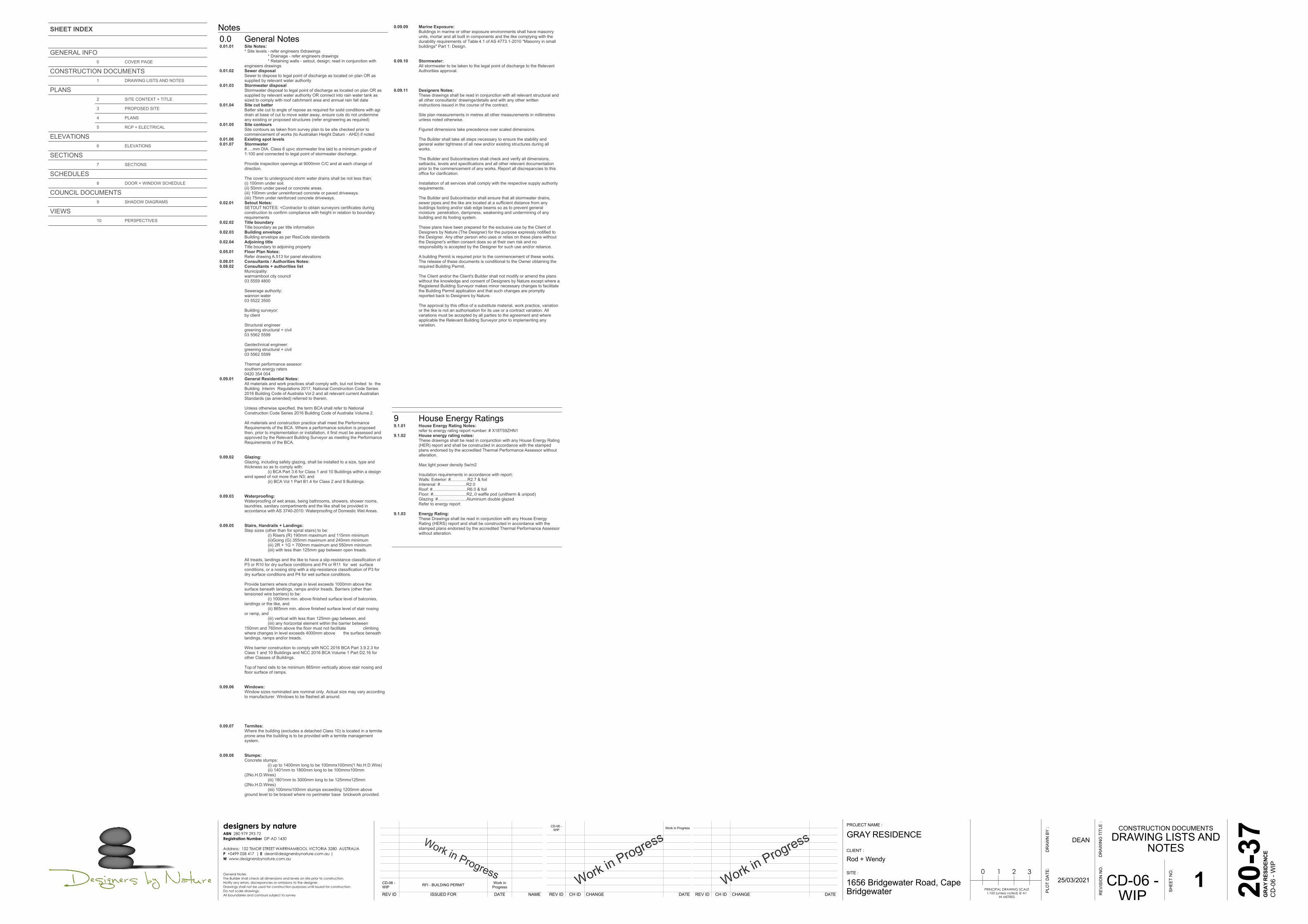
Notes0.0 General Notes0.01.01 Site Notes:
* Site levels - refer engineers ©drawings * Drainage - refer engineers drawings * Retaining walls - setout, design; read in conjunction withengineers drawings
0.01.02 Sewer disposalSewer to dispose to legal point of discharge as located on plan OR assupplied by relevant water authority
0.01.03 Stormwater disposalStormwater disposal to legal point of discharge as located on plan OR assupplied by relevant water authority OR connect into rain water tank assized to comply with roof catchment area and annual rain fall data
0.01.04 Site cut batterBatter site cut to angle of repose as required for soild conditions with agidrain at base of cut to move water away, ensure cuts do not undermineany existing or proposed structures (refer engineering as required)
0.01.05 Site contoursSite contours as taken from survey plan to be site checked prior tocommencement of works (to Australian Height Datum - AHD) if noted
0.01.06 Existing spot levels0.01.07 Stormwater
#.....mm DIA. Class 6 upvc stormwater line laid to a minimum grade of1:100 and connected to legal point of stormwater discharge.
Provide inspection openings at 9000mm C/C and at each change ofdirection.
The cover to underground storm water drains shall be not less than;(i) 100mm under soil.(ii) 50mm under paved or concrete areas.(iii) 100mm under unreinforced concrete or paved driveways.(iiii) 75mm under reinforced concrete driveways.
0.02.01 Setout Notes:SETOUT NOTES: <Contractor to obtain surveyors certificates duringconstruction to confirm compliance with height in relation to boundaryrequirements
0.02.02 Title boundaryTitle boundary as per title information
0.02.03 Building envelopeBuilding envelope as per ResCode standards
0.02.04 Adjoining titleTitle boundary to adjoining property
0.05.01 Floor Plan Notes:Refer drawing A.513 for panel elevations
0.08.01 Consultants / Authorities Notes:0.08.02 Consultants + authorities list
Municipality:warrnambool city council03 5559 4800
Sewerage authority:wannon water03 5522 3500
Building surveyor:by client
Structural engineergreening structural + civil03 5562 5599
Geotechnical engineer:greening structural + civil03 5562 5599
Thermal performance assesor:southern energy raters0420 354 004
0.09.01 General Residential Notes:All materials and work practices shall comply with, but not limited to theBuilding Interim Regulations 2017, National Construction Code Series2016 Building Code of Australia Vol 2 and all relevant current AustralianStandards (as amended) referred to therein.
Unless otherwise specified, the term BCA shall refer to NationalConstruction Code Series 2016 Building Code of Australia Volume 2.
All materials and construction practice shall meet the PerformanceRequirements of the BCA. Where a performance solution is proposedthen, prior to implementation or installation, it first must be assessed andapproved by the Relevant Building Surveyor as meeting the PerformanceRequirements of the BCA.
0.09.02 Glazing:Glazing, including safety glazing, shall be installed to a size, type andthickness so as to comply with: (i) BCA Part 3.6 for Class 1 and 10 Buildings within a design wind speed of not more than N3; and (ii) BCA Vol 1 Part B1.4 for Class 2 and 9 Buildings.
0.09.03 Waterproofing:Waterproofing of wet areas, being bathrooms, showers, shower rooms,laundries, sanitary compartments and the like shall be provided inaccordance with AS 3740-2010: Waterproofing of Domestic Wet Areas.
0.09.05 Stairs, Handrails + Landings:Step sizes (other than for spiral stairs) to be: (i) Risers (R) 190mm maximum and 115mm minimum (ii)Going (G) 355mm maximum and 240mm minimum (iii) 2R + 1G = 700mm maximum and 550mm minimum (iiii) with less than 125mm gap between open treads.
All treads, landings and the like to have a slip-resistance classification ofP3 or R10 for dry surface conditions and P4 or R11 for wet surfaceconditions, or a nosing strip with a slip-resistance classification of P3 fordry surface conditions and P4 for wet surface conditions.
Provide barriers where change in level exceeds 1000mm above thesurface beneath landings, ramps and/or treads. Barriers (other thantensioned wire barriers) to be: (i) 1000mm min. above finished surface level of balconies, landings or the like, and (ii) 865mm min. above finished surface level of stair nosing or ramp, and (iii) vertical with less than 125mm gap between, and (iiii) any horizontal element within the barrier between 150mm and 760mm above the floor must not facilitate climbingwhere changes in level exceeds 4000mm above the surface beneathlandings, ramps and/or treads.
Wire barrier construction to comply with NCC 2016 BCA Part 3.9.2.3 forClass 1 and 10 Buildings and NCC 2016 BCA Volume 1 Part D2.16 forother Classes of Buildings.
Top of hand rails to be minimum 865mm vertically above stair nosing andfloor surface of ramps.
0.09.06 Windows:Window sizes nominated are nominal only. Actual size may vary accordingto manufacturer. Windows to be flashed all around.
0.09.07 Termites:Where the building (excludes a detached Class 10) is located in a termiteprone area the building is to be provided with a termite managementsystem.
0.09.08 Stumps:Concrete stumps: (i) up to 1400mm long to be 100mmx100mm(1 No.H.D.Wire) (ii) 1401mm to 1800mm long to be 100mmx100mm (2No.H.D.Wires) (iii) 1801mm to 3000mm long to be 125mmx125mm (2No.H.D.Wires) (iiii) 100mmx100mm stumps exceeding 1200mm above ground level to be braced where no perimeter base brickwork provided.
0.09.09 Marine Exposure:Buildings in marine or other exposure environments shall have masonryunits, mortar and all built in components and the like complying with thedurability requirements of Table 4.1 of AS 4773.1-2010 "Masonry in smallbuildings" Part 1: Design.
0.09.10 Stormwater:All stormwater to be taken to the legal point of discharge to the RelevantAuthorities approval.
0.09.11 Designers Notes:These drawings shall be read in conjunction with all relevant structural andall other consultants' drawings/details and with any other writteninstructions issued in the course of the contract.
Site plan measurements in metres all other measurements in millimetresunless noted otherwise.
Figured dimensions take precedence over scaled dimensions.
The Builder shall take all steps necessary to ensure the stability andgeneral water tightness of all new and/or existing structures during allworks.
The Builder and Subcontractors shall check and verify all dimensions,setbacks, levels and specifications and all other relevant documentationprior to the commencement of any works. Report all discrepancies to thisoffice for clarification.
Installation of all services shall comply with the respective supply authorityrequirements.
The Builder and Subcontractor shall ensure that all stormwater drains,sewer pipes and the like are located at a sufficient distance from anybuildings footing and/or slab edge beams so as to prevent generalmoisture penetration, dampness, weakening and undermining of anybuilding and its footing system.
These plans have been prepared for the exclusive use by the Client ofDesigners by Nature (The Designer) for the purpose expressly notified tothe Designer. Any other person who uses or relies on these plans withoutthe Designer's written consent does so at their own risk and noresponsibility is accepted by the Designer for such use and/or reliance.
A building Permit is required prior to the commencement of these works.The release of these documents is conditional to the Owner obtaining therequired Building Permit.
The Client and/or the Client's Builder shall not modify or amend the planswithout the knowledge and consent of Designers by Nature except where aRegistered Building Surveyor makes minor necessary changes to facilitatethe Building Permit application and that such changes are promptlyreported back to Designers by Nature.
The approval by this office of a substitute material, work practice, variationor the like is not an authorisation for its use or a contract variation. Allvariations must be accepted by all parties to the agreement and whereapplicable the Relevant Building Surveyor prior to implementing anyvariation.
9 House Energy Ratings9.1.01 House Energy Rating Notes:
refer to energy rating report number: # X18T59ZHN19.1.02 House energy rating notes:
These drawings shall be read in conjunction with any House Energy Rating(HER) report and shall be constructed in accordance with the stampedplans endorsed by the accredited Thermal Performance Assessor withoutalteration.
Max light power density 5w/m2
Insulation requirements in accordance with report;Walls: Exterior: #..............R2.7 & foilInterenal: #......................R2.0Roof: #.............................R6.0 & foilFloor: #............................R2,.0 waffle pod (unitherm & unipod)Glazing: #........................Aluminium double glazedRefer to energy report
9.1.03 Energy Rating:These Drawings shall be read in conjunction with any House EnergyRating (HERS) report and shall be constructed in accordance with thestamped plans endorsed by the accredited Thermal Performance Assessorwithout alteration.
Work in Progress
Work in Progress
REV ID CH ID CHANGE DATE REV ID CH ID CHANGE DATE
CD-06 -WIP Work in Progress
Work in Progress
REV ID ISSUED FOR DATE NAME
TP-02
TP-03
CD-01
CD-02
CD-03
CD-04
CD-06 -WIP
MODEL FOR CLIENT SIGN OFF BEFOREAPPLYING TO PLANNING
PLANNING APPLICATION
PRELIMINARY CONSTRUCTION - DISCUSSIONWITH ENGINEER
ENGINEERING + ER SET
ISSUED FOR CONSTRUCTION
ISSUED FOR CONSTRUCTION
RFI - BUILDING PERMIT
4/08/2020
13/09/2020
20/10/2020
6/11/2020
3/12/2020
14/12/2020
Work inProgress
Dean Picken
Dean Picken
Dean Picken
Dean A Picken
Alice Piazzoli
Jamie Drew
PLO
T D
ATE:
DR
AWN
BY
:
GRAY RESIDENCE
1656 Bridgewater Road, CapeBridgewater
Rod + Wendy
PLANSSITE CONTEXT +
TITLE
PROJECT NAME :
DR
AWIN
G T
ITLE
:
CLIENT :
SITE :
20-3
7
SHEE
T N
O.
2
REV
ISIO
N N
O.
CD-06 -WIP
DEAN
25/03/2021PRINCIPAL DRAWING SCALE
1:100 (unless noted) @ A1IN METRES
0 1 2 3
GRA
Y RE
SIDE
NCE
CD
-06
- WIP
designers by natureABN 280 979 293 72Registration Number DP-AD 1430
Address: 152 TIMOR STREET WARRNAMBOOL VICTORIA 3280 AUSTRALIAP +0499 058 417 | E [email protected] |W www.designersbynature.com.au
General NotesThe Builder shall check all dimensions and levels on site prior to construction.Notify any errors, discrepancies or omissions to the designer.Drawings shall not be used for construction purposes until issued for construction.Do not scale drawings.All boundaries and contours subject to survey
N
+5,500 +5,500
+6,000
+6,500
+7,000
+7,500
+8,000
+8,500
+9,000
+9,500
+10,000
+10,500
+11,000
+11,500
+12,000+12,500
+13,000
+13,500+14,000
+14,500+15,000 +11,000
0.02.020.01.06 0.01.05
2.30.03
title boundary 18,280mm 233°4'00"
title boundary 18,280mm 53°4'00"
title
bou
ndar
y
32,0
00m
m
1
43°4
'00"
title
bou
ndar
y
32,0
00m
m
1
43°4
'00"
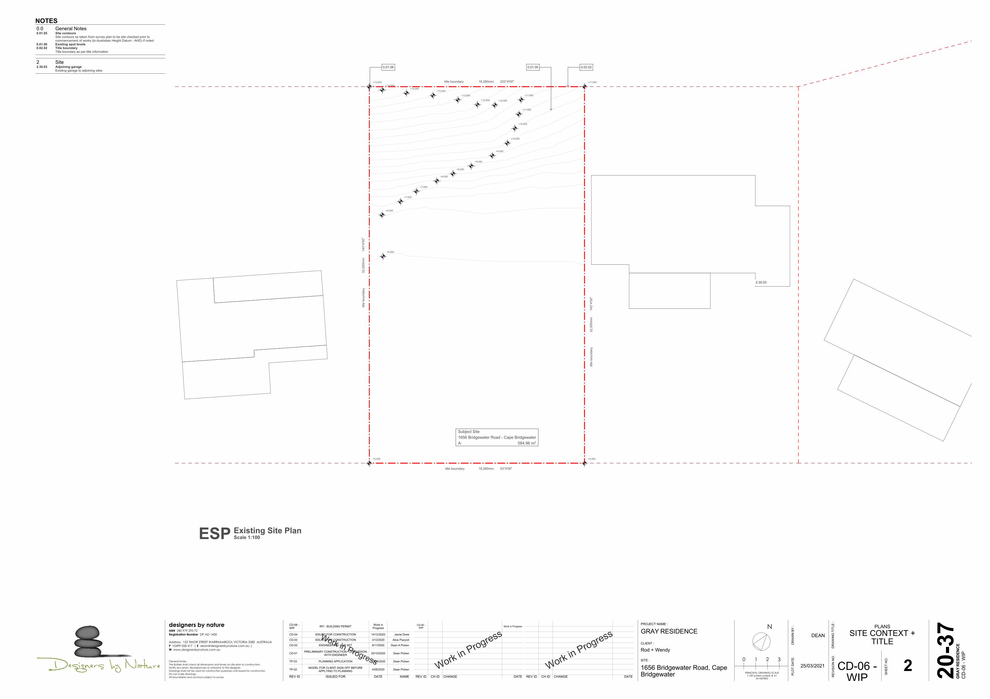
Subject Site1656 Bridgewater Road - Cape BridgewaterA: 584.96 m2
NOTES0.0 General Notes0.01.05 Site contours
Site contours as taken from survey plan to be site checked prior tocommencement of works (to Australian Height Datum - AHD) if noted
0.01.06 Existing spot levels0.02.02 Title boundary
Title boundary as per title information
2 Site2.30.03 Adjoining garage
Existing garage to adjoining sites
ESP Existing Site PlanScale 1:100

Work in Progress
Work in Progress
REV ID CH ID CHANGE DATE REV ID CH ID CHANGE DATE
CD-06 -WIP Work in Progress
Work in Progress
REV ID ISSUED FOR DATE NAMETP-03
CD-01
CD-02
CD-03
CD-04
CD-05
CD-06 -WIP
PLANNING APPLICATION
PRELIMINARY CONSTRUCTION - DISCUSSIONWITH ENGINEER
ENGINEERING + ER SET
ISSUED FOR CONSTRUCTION
ISSUED FOR CONSTRUCTION
RFI - BUILDING PERMIT
RFI - BUILDING PERMIT
13/09/2020
20/10/2020
6/11/2020
3/12/2020
14/12/2020
12/02/2021
Work inProgress
Dean Picken
Dean Picken
Dean A Picken
Alice Piazzoli
Jamie Drew
Alice Piazzoli
PLO
T D
ATE:
DR
AWN
BY
:
GRAY RESIDENCE
1656 Bridgewater Road, CapeBridgewater
Rod + Wendy
PLANSPROPOSED SITE
PROJECT NAME :
DR
AWIN
G T
ITLE
:
CLIENT :
SITE :
20-3
7
SHEE
T N
O.
3
REV
ISIO
N N
O.
CD-06 -WIP
DEAN
25/03/2021PRINCIPAL DRAWING SCALE
1:100 (unless noted) @ A1IN METRES
0 1 2 3
GRA
Y RE
SIDE
NCE
CD
-06
- WIP
designers by natureABN 280 979 293 72Registration Number DP-AD 1430
Address: 152 TIMOR STREET WARRNAMBOOL VICTORIA 3280 AUSTRALIAP +0499 058 417 | E [email protected] |W www.designersbynature.com.au
General NotesThe Builder shall check all dimensions and levels on site prior to construction.Notify any errors, discrepancies or omissions to the designer.Drawings shall not be used for construction purposes until issued for construction.Do not scale drawings.All boundaries and contours subject to survey
N
8,12
5re
siden
ce s
etba
ck a
vera
ge o
ver 3
adj
oini
ng s
ites
14,8
818,
994
2,20013,2752,805
3,20010,1504,930
9,00
0se
tbac
k
2,805
11,7
60
3,200
2,295
6,980
6,443
2,784
3,826
+5,578
+6,300
+9,155
+13,187
+7,692
+6,300
+5,842
2.30.06
2.30.07
7.09.017.09.02
2.01.042.01.05
2.01.02
7.09.02
7.09.04
7.10.01
7.10.02
7.03.02 7.02.14
2.30.08
2.30.09
4.30.05
7.09.04
title boundary 18,280mm 233°4'00"
title boundary 18,280mm 53°4'00"
title
bou
ndar
y
32,0
00m
m
1
43°4
'00"
title
bou
ndar
y
32,0
00m
m
1
43°4
'00"
Subject Site1656 Bridgewater Road - Cape BridgewaterA: 584.96 m2Driveway
A: 81.93 m2
Proposed DwellingA: 184.74 m2
AREA ANALYSISLEVELsite
---
01
02
03
04
Subject Site
Proposed Dwelling
Driveway
Garden Area
AREA
---
585.0
184.7
81.9
325.2
TOTAL %
100%
54%
Garden Area55% supplied (required 35%)A: 325.23 m2
500
2,60
5
4.03.01
7.11.02
3.08.07
4.02.29
4.01.01
4.02.13 4.02.07 4.02.13
4.02.07
4.02.13
4.02.13
1 de
gree
fall
Notes2 Site2.01.02 Vehicle crossing
crossover as required by local authorities2.01.04 Paving
Permeable paving in concrete with grass infill2.01.05 Driveway
Driveway via an all weather access track with dimensions adequateaccomodate emergency services vehicles (4000mm wide)
2.30.06 First floor residenceProposed upper level residence
2.30.07 BalconyProposed upper level balcony
2.30.08 Adjoining windowHabitable
2.30.09 Adjoining windowNon Habitable
3 Structure3.08.07 Fascia
Fascia with capping as selected by client
4 Enclosure4.01.01 Line of wall below4.02.07 Gutter - general
colorbond # gutter in colour as nominated (refer colour scheme if supplied orclient) refer to engineers stormwater / roof drainage plan for all roof drainagedetails
4.02.13 Downpipe - roundcolorbond pre-finished OR uPVC 100mm diametre round downpipe connectedto legal point of discharge - refer enegineers roof drainage plan - legal point ofdicharge could be local water authority supply, rain water tank or localisedsoakage pits
4.02.29 Gutter @ Balcony floor levelcolorbond gutter in colour as nominated with downpiape (refer colour schemeif supplied or client) refer to engineers stormwater / roof drainage plan for allroof drainage details
4.03.01 Roof sheeting - klip-lok 700 hi strengthcolorbond klip-lok 700 hi strength 0.48 in Monument as selected by client.Install with support as follows: end spans of 2350mm + internal spans of2800mm - refer to sections and elevations for roof pitch
4.30.05 ScreeningProvide screening at least 600mm wide from wall surface at the edge ofwindow opening for the height of W-02 with no more than 25% transparencyOR slats to avoid overviewing back to habitable windows or SPOS within 9m
7 Services7.02.14 Soak pit
Soak pit design and location as per engineer drawings. refer to engineerdrawing and Report "Site Stormwater Layout and Pit Detail 20-284 SW-02".
7.03.02 Sewer lineSewer line connected to septic tank as per engineers drawings. Refer toengineer drawing "Land Capability Assessment 20-248 LCA1"
7.09.01 CFA accessCFA access to rain water tank
7.09.02 Rain water tanks5000L water tank connected to flushing toiletsRain water tank to be plumbed directly to all flushing toilets, colour to matchwall cladding - 10 000 L as determined by clients.
7.09.04 CFA couplingProvide CFA coupling out front of residence and ensure tank water supply isprotected for CFA use - 10,000 ltrs
7.10.01 Septic systemSeptic system as approved by health inspector. Treatment system as perengieer drawings. Discharge to be in accordance with State EnvironmentalProtection Policy. Refer to engineer drawing "Land Capability Assessment 20-248 LCA1"
7.10.02 Collection wellCollection well 15'000Lt and turret with lid at surfaceas to access wellapproved by health inspector. Treatment system as per engieer drawings.Discharge to be in accordance with State Environmental Protection Policy.Refer to engineer drawing "Land Capability Assessment 20-248 LCA1"
7.11.02 Photovoltaic systemPhotovoltaic system as slected by clients and installed to comply with planningregulations / building code. Location and quantity to be confirmed by client.
PSP Proposed Site PlanScale 1:100 GAP Garden Area Plan
Scale 1:200RDP Roof Drainage PlanScale 1:100

Work in Progress
Work in Progress
REV ID CH ID CHANGE DATE REV ID CH ID CHANGE DATE
CD-06 -WIP Work in Progress
Work in Progress
REV ID ISSUED FOR DATE NAMETP-03
CD-01
CD-02
CD-03
CD-04
CD-05
CD-06 -WIP
PLANNING APPLICATION
PRELIMINARY CONSTRUCTION - DISCUSSIONWITH ENGINEER
ENGINEERING + ER SET
ISSUED FOR CONSTRUCTION
ISSUED FOR CONSTRUCTION
RFI - BUILDING PERMIT
RFI - BUILDING PERMIT
13/09/2020
20/10/2020
6/11/2020
3/12/2020
14/12/2020
12/02/2021
Work inProgress
Dean Picken
Dean Picken
Dean A Picken
Alice Piazzoli
Jamie Drew
Alice Piazzoli
PLO
T D
ATE:
DR
AWN
BY
:
GRAY RESIDENCE
1656 Bridgewater Road, CapeBridgewater
Rod + Wendy
PLANSPLANS
PROJECT NAME :
DR
AWIN
G T
ITLE
:
CLIENT :
SITE :
20-3
7
SHEE
T N
O.
4
REV
ISIO
N N
O.
CD-06 -WIP
DEAN
25/03/2021PRINCIPAL DRAWING SCALE
1:100 (unless noted) @ A1IN METRES
0 1 2 3
GRA
Y RE
SIDE
NCE
CD
-06
- WIP
designers by natureABN 280 979 293 72Registration Number DP-AD 1430
Address: 152 TIMOR STREET WARRNAMBOOL VICTORIA 3280 AUSTRALIAP +0499 058 417 | E [email protected] |W www.designersbynature.com.au
General NotesThe Builder shall check all dimensions and levels on site prior to construction.Notify any errors, discrepancies or omissions to the designer.Drawings shall not be used for construction purposes until issued for construction.Do not scale drawings.All boundaries and contours subject to survey
N
D-04 W-06
W-0
4
W-0
5D
-03
W-0
2
W-03
D-0
2
ID-0
1
ID-02
ID-0
6ID
-04
ID-0
5
ID-0
9
ID-08
ID-0
7
ID-0
9
ID-0
3
D-0
1
W-01
16 x
180
= 2
,880
UP1
2
3
4
5
6
7
8
9
10
11
12
13
14
15
16
6,11
02,
125
240
5,31
5St
air
140
240
5,87
0D
rivew
ay24
07,
440
Entry
+ R
umpu
s14
0
240
4,94
0G
arag
e90
1,55
0Li
nen
901,
000
903,
030
Rob
e24
0
240
3,00
0Be
d 2
901,
000
WC
901,
700
Bath
901,
700
Laun
dry
903,
030
Bed
324
0
2403,730Bed 3
90510907,345Stair + Rumpus
200
2801,965200
240 6,380Rumpus
90 51090
1,000Hall
90 2,640Laundry
240 76090
150
2404,130Bed 2
90510906,000Garage
902,125
2,05
088
66,
110
2,12
55,
765
9,00
0
2,445 9,760 1,000
70 925
2,05
088
62,
340
1,27
07,
660
2,66
0
2,875
2,805 13,275 2,200
2,805
240
6,02
0G
arag
e90
4,68
0R
umpu
s90
150
2,66
0
955
970
1,76
0
2,125 90 6,000Garage
90 1,600 90 2,040WC
240
901,
910
robe
+6,280
+6,300
+6,300
BB
A A
DD
EEFF
5.07.04
3.01.035.02.025.02.145.02.15
4.01.06
4.02.30
3.06.10
2.01.042.01.05
2.01.02
3.03.08
8.02.10
7.05.09
7.05.08
7.05.08
4.06.06
4.02.13
4.02.134.02.13
4.05.06
4.01.06
4.01.06
Entry
robe
linen
pan
landing
stairs up
shr
vanity
bench tr wm
return air
SD
SD
SD
DRIVEWAY Rumpus + EntryF: Timber Floor BoardsA: 37.45 m2
HallF: TimberA: 5.85 m2
Bed 3F: CarpetA: 12.84 m2
Bed 2F: CarpetA: 14.29 m2Garage
F: ConcreteA: 34.65 m2
VerandaF: ConcreteA: 10.05 m2
LaundryF: TileA: 4.43 m2
BathF: TileA: 4.47 m2
WCF: TileA: 2.01 m2
CC
D-06 D-05
W-01
W-0
7
W-13D-07
W-1
2
W-11
W-1
4
ID-1
1
ID-1
2
W-08 W-09 W-10
16 x
180
= 2
,880
UP1
2
3
4
5
6
7
8
9
10
11
12
13
14
15
16
BOX GUTTER
BB
A A
DD
EEFF
2,81
0Ba
lcon
y90
8,92
0M
eals
+ K
itche
n90
1,78
0Bu
tlers
240
140
13,5
50St
airs
+ M
eals
+ K
itche
n24
0
14,0
009,
000
2,445 10,610
90300
9010,130Balcony
2801,965Stairs
200
140
2,67
0Ba
lcon
y90
4,83
0Li
ving
902,
500
Balc
ony
901,
400
WIR
901,
790
En-s
240
3,61
02,
500
5,51
02,
310
13,220
2403,280En-s
904,500Bed 1
902,860Butlers
901,98090
907,870Balcony
904,930Kitchen
90
903,
280
240
+9,360
+9,360
+9,360
4.06.06
4.30.05
4.02.31
7.05.09
7.05.08
3.01.035.02.025.02.145.02.15
7.04.07
4.02.29
4.02.134.02.13
4.02.13
10.01.20
4.05.06
4.30.06
3.05.05
3.30.08
4.30.08
3.05.05
4.30.06
vanity
pan
shr
hanging / shelves
shelves
island bench
broom
down
roof
ove
r
ref
bench
ct +ov +rh
sink
dw
open to sky
balu
stra
de
void
bench
Bed 1F: CarpetA: 14.76 m2
LivingF: Timber Floor BoardsA: 27.26 m2
MealsF: Timber Floor BoardsA: 28.71 m2
KitchenF: Timber Floor BoardsA: 26.94 m2
ButlersF: Timber Floor BoardsA: 5.04 m2
BalconyF: Timber DeckA: 19.39 m2
BalconyF: Timber DeckA: 27.91 m2
WIRF: CarpetA: 4.58 m2
En-sF: TileA: 5.82 m2
CC
AREA ANALYSIS RESIDENCEZONE---
01
02
03
04
DESCRIPTION
---
First floor
Ground Floor
Garage
Veranda
Balcony
M. SQ.
---
135.7
101.9
39.7
48.7
49.0
Notes2 Site2.01.02 Vehicle crossing
crossover as required by local authorities2.01.04 Paving
Permeable paving in concrete with grass infill2.01.05 Driveway
Driveway via an all weather access track with dimensions adequateaccomodate emergency services vehicles (4000mm wide)
3 Structure3.01.03 Floor wastes - residential
Selected floor waste to suit the application to:Bathroom floors the minimum fall to the waste to be 1:100 (10mm per 1m).Shower areas with a vertical separation between the shower area and thewet area, such as a shower screen, hob, set-down or water stop, the fall tothe waste shall be 1:100.For all other shower areas the fall shall be a minimum of 1:80 (12.5mm over1m).Where falls flatter than 1:100 are proposed, the effectiveness of the floordrainage should be confirmed to ensure that water does not remain on thefinished floor, the water must drain away, with the exception of residualwater.Tiles may require diagonal cutting in the area around the waste to achievethe required falls, sufficient drainage and to ensure lipping is kept within theguidelines of AS 3958.1.
3.03.08 Paving slabPad for rainwater tanks to be seated on
3.05.05 Balustrade/handrailFrameless glass balustrade panels certified to perform to AustralianStandardsinstalled to manufacturers details and to comply with 'NCC VOL.2 3.9.2Barriers and Handrails'min total height of 1000mm above finished surface level as selected byclientno gaps to be larger than 125mm
3.06.10 ColumnStructural posts framed and clad with timber cladding to match adjoiningsurfaces
3.30.08 StairsFloating stairs on central spine to manufacturers details and specifications16x 180mm riser and 300mm tread with 30mm nosing2R+G=660Step sizes (other than for spiral stairs) to be: (i) Risers (R) 190mm maximum and 115mm minimum (ii)Going (G) 355mm maximum and 240mm minimum (iii) 2R + 1G = 700mm maximum and 550mm minimum (iiii) with less than 125mm gap between open treads.All treads, landings and the like to have a slip-resistance classification of P3or R10 for dry surface conditions and P4 or R11 for wet surfaceconditions, or a nosing strip with a slip-resistance classification of P3 for drysurface conditions and P4 for wet surface conditions.Provide barriers where change in level exceeds 1000mm above the surfacebeneath landings, ramps and/or treads. Barriers (other than tensioned wirebarriers) to be: (i) 1000mm min. above finished surface level of balconies, landings or the like, and (ii) 865mm min. above finished surface level of stair nosing orramp, and (iii) vertical with less than 125mm gap between, and (iiii) any horizontal element within the barrier between 150mm and 760mm above the floor must not facilitate climbingwhere changes in level exceeds 4000mm above the surface beneathlandings, ramps and/or treads.Top of hand rails to be minimum 865mm vertically above stair nosing andfloor surface of ramps.
4 Enclosure4.01.06 Line of wall above4.02.13 Downpipe - round
colorbond pre-finished OR uPVC 100mm diametre round downpipeconnected to legal point of discharge - refer enegineers roof drainage plan -legal point of dicharge could be local water authority supply, rain water tankor localised soakage pits
4.02.29 Gutter @ Balcony floor levelcolorbond gutter in colour as nominated with downpiape (refer colourscheme if supplied or client) refer to engineers stormwater / roof drainageplan for all roof drainage details
4.02.30 Downpipe - roundcolorbond pre-finished OR uPVC 100mm diametre round downpipeconnected to legal point of discharge - refer enegineers roof drainage plan -legal point of dicharge could be local water authority supply, rain water tankor localised soakage pitsconnected to sump within decking above
4.02.31 Floor box gutter - Beneath deckingFloor box gutter with sump (with overflow) and downpipe as per engineerdrawings
4.05.06 Timber claddingShiplap vertical timber cladding in species as slected by client for "fireresistanat index rating" as required for durability and fire resistanceClass 1 or 2 durability Naturally Greyed
4.06.06 Blockwork - concrete exposedConcrete block in natural grey finish - stretcher bond pattern
4.30.05 ScreeningProvide screening at least 600mm wide from wall surface at the edge ofwindow opening for the height of W-02 with no more than 25% transparencyOR slats to avoid overviewing back to habitable windows or SPOS within9m
4.30.06 OverviewingNo overviewing from windows as sill is 1700mm above finished floor level
4.30.08 Glass balustradeFrameless glass balustrade certified to perform to Australian Standards bymanufacturerInstalled to manufacturers details and to comply with 'NCC VOL.2 3.9.2Barriers and Handrails'Min total height of 1000mm above finished surface level (decking) asselected by clientNo gaps to be larger than 125mm
5 Interior5.02.02 Plasterboard - wet area
Generally form 10mm Aquacheck or similar plasterboard lining to wet areasover framing @ 450mm ctr's
5.02.14 TilingTiling to shower areaTiling to remaining wall areas TBC by client
5.02.15 ScreenGlass panel screen to seperate shower area
5.07.04 Exposed concreteConcrete floor exposed and densified as nominated by engineer and finishas preferred by client
7 Services7.04.07 Cooktop w/ integrated exhaust
cook top with integrated extraction fan within hob - client to confirm7.05.08 Smoke detector
Interconnected smoke detectors installed in strict accordance withAS3786. Hardwire to mains
7.05.09 Exhaust fanExhaust fan as selected by clientsealed in accordance with energy report
8 External8.02.10 Retaining wall
Retaining wall as per engineer drawings. Refer to engineer drawing "Slaband Footing Layout Plan 20-284 S04"
10 Heating + Cooling10.01.20 Ceiling fan
Ceiling fan as selected by client GFP Ground Floor PlanScale 1:100 FFP First Floor Plan
Scale 1:100

Work in Progress
Work in Progress
REV ID CH ID CHANGE DATE REV ID CH ID CHANGE DATE
CD-06 -WIP Work in Progress
Work in Progress
REV ID ISSUED FOR DATE NAME
CD-06 -WIP RFI - BUILDING PERMIT Work in
Progress
PLO
T D
ATE:
DR
AWN
BY
:
GRAY RESIDENCE
1656 Bridgewater Road, CapeBridgewater
Rod + Wendy
PLANSRCP + ELECTRICAL
PROJECT NAME :
DR
AWIN
G T
ITLE
:
CLIENT :
SITE :
20-3
7
SHEE
T N
O.
5
REV
ISIO
N N
O.
CD-06 -WIP
DEAN
25/03/2021PRINCIPAL DRAWING SCALE
1:100 (unless noted) @ A1IN METRES
0 1 2 3
GRA
Y RE
SIDE
NCE
CD
-06
- WIP
designers by natureABN 280 979 293 72Registration Number DP-AD 1430
Address: 152 TIMOR STREET WARRNAMBOOL VICTORIA 3280 AUSTRALIAP +0499 058 417 | E [email protected] |W www.designersbynature.com.au
General NotesThe Builder shall check all dimensions and levels on site prior to construction.Notify any errors, discrepancies or omissions to the designer.Drawings shall not be used for construction purposes until issued for construction.Do not scale drawings.All boundaries and contours subject to survey
SD
SD
SD
14.01.04
7.05.09
14.01.06
14.01.06
7.05.08
Verandaflatsoffit liningStair void
Rumpus2700 high ceilingplaster
Bed 32700 high ceilingplaster
Laundry2700 high ceilingwet area plaster
Shower2700 high ceilingwet area plaster
WC2700 high ceilingplasterHall
2700 highplaster
Bed 22700 high ceilingplaster
Garage2720 high ceilingplaster
Coverflatsoffit liner
up
VERANDA LIGHTING ALLOWANCE4 WATTS / M. SQ.A: 35.39 m2
141.56 WATT ALLOWANCE
GARAGE COVER LIGHTING ALLOWANCE4 WATTS / M. SQ.A: 14.24 m2
56.96 WATT ALLOWANCE
INDOOR LIGHTING ALLOWANCE GROUND FLOOR5 WATTS / M. SQ.A: 121.19 m2
605.95 WATT ALLOWANCERefer to accompanying energy report
SD
SD
14.01.04
14.01.06
7.05.08
14.01.07
4.02.13
7.05.09
14.01.07
7.05.08
Void to sky
Balcony2650 high flatsoffit lining
Meals2650 high ceilingplaster
Ens2650 high ceilingwet area plaster
Living2650 high ceilingplaster
Balcony2650 high flatsoffit lining
Kitchen2650 high ceilingplaster
Bed 12650 high ceilingplaster
WIR2650 high ceilingplaster
Pantry2650 high ceilingplaster
VERANDA LIGHTING ALLOWANCE4 WATTS / M. SQ.A: 16.17 m2
64.68 WATT ALLOWANCE
INDOOR LIGHTING ALLOWANCE FIRST FLOOR5 WATTS / M. SQ.A: 121.14 m2
605.7 WATT ALLOWANCERefer to accompanying energy report
VERANDA LIGHTING ALLOWANCE4 WATTS / M. SQ.A: 12.65 m2
50.6 WATT ALLOWANCE
16 x
180
= 2
,880
UP1
2
3
4
5
6
7
8
9
10
11
12
13
14
15
16
2 2
2
22
2
2
2
2
22
2
2 2
2
7.05.037.05.11
DUAL GARAGE
BED 2
WC
SHR
LAUNDRY
BED 3
RUMPUS
VERANDAENTRY
landing
stairs
HALL
16 x
180
= 2
,880
UP1
2
3
4
5
6
7
8
9
10
11
12
13
14
15
16
2 2
2
2
2
2
2
2
2
2
2 2 2 2 2 2
2
7.05.037.05.11
Notes4 Enclosure4.02.13 Downpipe - round
colorbond pre-finished OR uPVC 100mm diametre round downpipe connectedto legal point of discharge - refer enegineers roof drainage plan - legal point ofdicharge could be local water authority supply, rain water tank or localisedsoakage pits
7 Services7.05.03 Electrical drawings indicative only
Refer to electrical layout drawings by engineer or similarly qualified profesionalto ensure:all switches are 500mm min. from internal cornersGPOs in both accessible WC facilities are located at 900-1000mm from FFLToggle switches to AS1428.1 are provided to accessible facilitiesLighting, alarm and indicator lamp controls to all cool rooms complying withBCA col 1 part G1.2Height of GPO's TBC by client
7.05.08 Smoke detectorInterconnected smoke detectors installed in strict accordance withAS3786. Hardwire to mains
7.05.09 Exhaust fanExhaust fan as selected by clientsealed in accordance with energy report
7.05.11 GPO
14 Lighting14.01.04 Downlights
Low power LED14.01.06 Downlights - Outdoor
Low power LED suitable for external use14.01.07 Pendant Light
Low power LEDas selected by client
RCPReflected Ceiling PlanGround FloorScale 1:100 RCP
Reflected Ceiling PlanFirst FloorScale 1:100
ELPElectrical Layout PlanGround FloorScale 1:100 ELP
Electrical Layout PlanFirst FloorScale 1:100
Work in Progress
Work in Progress
REV ID CH ID CHANGE DATE REV ID CH ID CHANGE DATE
CD-06 -WIP Work in Progress
Work in Progress
REV ID ISSUED FOR DATE NAMETP-03
CD-01
CD-02
CD-03
CD-04
CD-05
CD-06 -WIP
PLANNING APPLICATION
PRELIMINARY CONSTRUCTION - DISCUSSIONWITH ENGINEER
ENGINEERING + ER SET
ISSUED FOR CONSTRUCTION
ISSUED FOR CONSTRUCTION
RFI - BUILDING PERMIT
RFI - BUILDING PERMIT
13/09/2020
20/10/2020
6/11/2020
3/12/2020
14/12/2020
12/02/2021
Work inProgress
Dean Picken
Dean Picken
Dean A Picken
Alice Piazzoli
Jamie Drew
Alice Piazzoli
PLO
T D
ATE:
DR
AWN
BY
:
GRAY RESIDENCE
1656 Bridgewater Road, CapeBridgewater
Rod + Wendy
ELEVATIONSELEVATIONS
PROJECT NAME :
DR
AWIN
G T
ITLE
:
CLIENT :
SITE :
20-3
7
SHEE
T N
O.
6
REV
ISIO
N N
O.
CD-06 -WIP
DEAN
25/03/2021PRINCIPAL DRAWING SCALE
1:100 (unless noted) @ A1IN METRES
0 1 2 3
GRA
Y RE
SIDE
NCE
CD
-06
- WIP
designers by natureABN 280 979 293 72Registration Number DP-AD 1430
Address: 152 TIMOR STREET WARRNAMBOOL VICTORIA 3280 AUSTRALIAP +0499 058 417 | E [email protected] |W www.designersbynature.com.au
General NotesThe Builder shall check all dimensions and levels on site prior to construction.Notify any errors, discrepancies or omissions to the designer.Drawings shall not be used for construction purposes until issued for construction.Do not scale drawings.All boundaries and contours subject to survey
+6,3002 level one
+6,3002 level one
+9,3603 level two
+9,3603 level two
+6,3002 level one
+6,3002 level one
+9,3603 level two
+9,3603 level two
+5,975
+12,010
4.07.08 4.07.028.02.10
1.01.06
W-07
4.02.074.02.13
7.09.017.09.02
4.06.06
D-02
2.01.09
4.05.06 4.07.23
ceiling line
+6,3002 level one
+6,3002 level one
+9,3603 level two
+9,3603 level two
+6,280
3,06
02,
650
+12,810
2,2002,805
+12,810
+12,010
4.30.08 4.07.02
4.06.06
1.01.06
4.05.06
W-01 D-06
D-04 W-06 W-03
8.02.10 8.02.10
0.02.03
D-05
0.02.02
1.01.081.01.08
Height of ceiling
Height of ceiling
+6,3002 level one
+9,3603 level two
+6,300+5,975
+12,810
4.07.024.30.06 1.01.064.05.06
W-14
D-01 D-03
W-05
W-02
4.30.05 8.02.107.09.017.09.02
4.02.074.02.134.06.06
+6,3002 level one
+9,3603 level two
+12,539
2,200 2,805
4.02.07 4.03.01
7.09.02
4.05.06 8.02.108.02.10 4.02.074.02.13
W-10 W-09 W-08
0.02.03
Height of ceiling
Height of ceiling
Height of ceiling
Height of ceiling
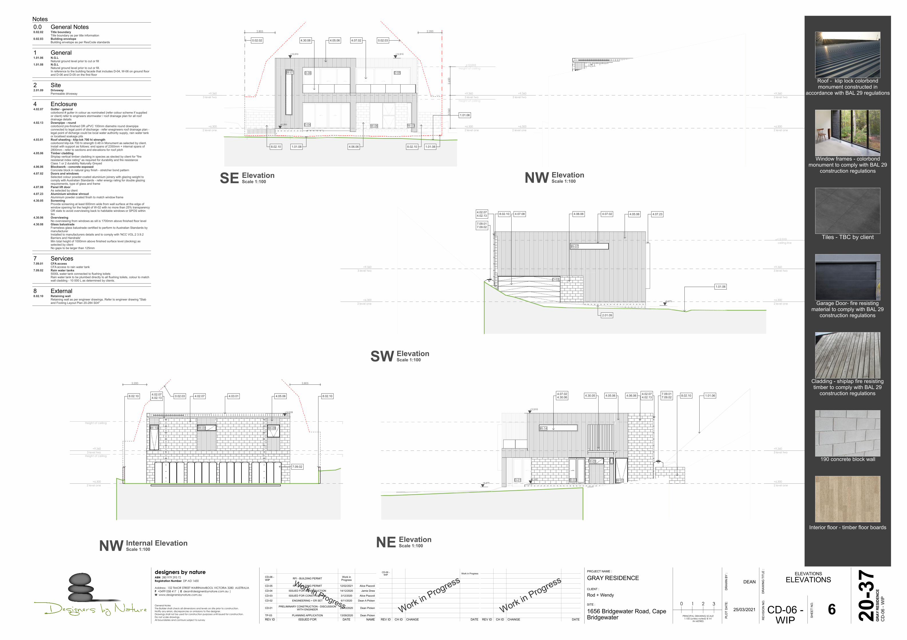
Notes0.0 General Notes0.02.02 Title boundary
Title boundary as per title information0.02.03 Building envelope
Building envelope as per ResCode standards
1 General1.01.06 N.G.L
Natural ground level prior to cut or fill1.01.08 N.G.L
Natural ground level prior to cut or fill.In reference to the building facade that includes D-04, W-06 on ground floorand D-06 and D-05 on the first floor
2 Site2.01.09 Driveway
Permeable driveway
4 Enclosure4.02.07 Gutter - general
colorbond # gutter in colour as nominated (refer colour scheme if suppliedor client) refer to engineers stormwater / roof drainage plan for all roofdrainage details
4.02.13 Downpipe - roundcolorbond pre-finished OR uPVC 100mm diametre round downpipeconnected to legal point of discharge - refer enegineers roof drainage plan -legal point of dicharge could be local water authority supply, rain water tankor localised soakage pits
4.03.01 Roof sheeting - klip-lok 700 hi strengthcolorbond klip-lok 700 hi strength 0.48 in Monument as selected by client.Install with support as follows: end spans of 2350mm + internal spans of2800mm - refer to sections and elevations for roof pitch
4.05.06 Timber claddingShiplap vertical timber cladding in species as slected by client for "fireresistanat index rating" as required for durability and fire resistanceClass 1 or 2 durability Naturally Greyed
4.06.06 Blockwork - concrete exposedConcrete block in natural grey finish - stretcher bond pattern
4.07.02 Doors and windowsSelected colour powder-coated aluminium joinery with glazing weight tocomply with Australian Standards - refer energy rating for double glazingrequirements, type of glass and frame
4.07.08 Panel lift doorAs selected by client
4.07.23 Aluminium window shroudAluminium powder coated finsih to match window frame
4.30.05 ScreeningProvide screening at least 600mm wide from wall surface at the edge ofwindow opening for the height of W-02 with no more than 25% transparencyOR slats to avoid overviewing back to habitable windows or SPOS within9m
4.30.06 OverviewingNo overviewing from windows as sill is 1700mm above finished floor level
4.30.08 Glass balustradeFrameless glass balustrade certified to perform to Australian Standards bymanufacturerInstalled to manufacturers details and to comply with 'NCC VOL.2 3.9.2Barriers and Handrails'Min total height of 1000mm above finished surface level (decking) asselected by clientNo gaps to be larger than 125mm
7 Services7.09.01 CFA access
CFA access to rain water tank7.09.02 Rain water tanks
5000L water tank connected to flushing toiletsRain water tank to be plumbed directly to all flushing toilets, colour to matchwall cladding - 10 000 L as determined by clients.
8 External8.02.10 Retaining wall
Retaining wall as per engineer drawings. Refer to engineer drawing "Slaband Footing Layout Plan 20-284 S04"
NW ElevationScale 1:100
SW ElevationScale 1:100
SE ElevationScale 1:100
NE ElevationScale 1:100NW Internal Elevation
Scale 1:100
Roof - klip lock colorbondmonument constructed in
accordance with BAL 29 regulations
Window frames - colorbondmonument to comply with BAL 29
construction regulations
Tiles - TBC by client
190 concrete block wall
Interior floor - timber floor boards
Cladding - shiplap fire resistingtimber to comply with BAL 29
construction regulations
Garage Door- fire resistingmaterial to comply with BAL 29
construction regulations

Work in Progress
Work in Progress
REV ID CH ID CHANGE DATE REV ID CH ID CHANGE DATE
CD-06 -WIP Work in Progress
Work in Progress
REV ID ISSUED FOR DATE NAME
TP-02
TP-03
CD-01
CD-02
CD-03
CD-04
CD-06 -WIP
MODEL FOR CLIENT SIGN OFF BEFOREAPPLYING TO PLANNING
PLANNING APPLICATION
PRELIMINARY CONSTRUCTION - DISCUSSIONWITH ENGINEER
ENGINEERING + ER SET
ISSUED FOR CONSTRUCTION
ISSUED FOR CONSTRUCTION
RFI - BUILDING PERMIT
4/08/2020
13/09/2020
20/10/2020
6/11/2020
3/12/2020
14/12/2020
Work inProgress
Dean Picken
Dean Picken
Dean Picken
Dean A Picken
Alice Piazzoli
Jamie Drew
PLO
T D
ATE:
DR
AWN
BY
:
GRAY RESIDENCE
1656 Bridgewater Road, CapeBridgewater
Rod + Wendy
SECTIONSSECTIONS
PROJECT NAME :
DR
AWIN
G T
ITLE
:
CLIENT :
SITE :
20-3
7
SHEE
T N
O.
7
REV
ISIO
N N
O.
CD-06 -WIP
DEAN
25/03/2021PRINCIPAL DRAWING SCALE
1:100 (unless noted) @ A1IN METRES
0 1 2 3
GRA
Y RE
SIDE
NCE
CD
-06
- WIP
designers by natureABN 280 979 293 72Registration Number DP-AD 1430
Address: 152 TIMOR STREET WARRNAMBOOL VICTORIA 3280 AUSTRALIAP +0499 058 417 | E [email protected] |W www.designersbynature.com.au
General NotesThe Builder shall check all dimensions and levels on site prior to construction.Notify any errors, discrepancies or omissions to the designer.Drawings shall not be used for construction purposes until issued for construction.Do not scale drawings.All boundaries and contours subject to survey
+6,3002 level one
+6,3002 level one
+9,3603 level two
+9,3603 level two
+6,300
+9,360
3,06
02,
700
2,40
066
02,
590
60
3.30.08
1.01.06
D-06
D-04 W-06 W-03
4.03.01
W-08
3.03.09
Balcony
VerandaStairs
ceiling line
+6,3002 level one
+6,3002 level one
+9,3603 level two
+9,3603 level two
2,70
036
02,
650
800
+9,360
+6,300 +6,280
+12,010
3.09.01 4.02.044.03.01
W-03
W-11
W-01
3.03.09
4.05.06
Bed 02 Garage
Butlers KitchenBed 01En-s
Driveway
ceiling line
+6,3002 level one
+9,3603 level two
6,21
0
2,72
036
02,
650
50
+6,300
+9,360
3.09.014.10.02 8.02.10
ID-12ID-11W-07 W-12
ID-03
D-01 ID-04 ID-06 ID-07 ID-09
3.09.014.03.01 3.03.094.05.06
8.04.05 4.02.07 4.02.074.02.13
Living
ceiling line
Balcony Balcony Wir En-s
Bed 02WcShrLaundryBed 03Veranda
300
2,70
036
02,
650
650
6,36
0
9,000 14,805
180
FFL+6,300
FFL+9,360
+5,975
30
180
1,00
0
3.30.08
1.01.06
ID-11 W-12 W-14
D-01D-02
8.02.10 3.09.014.02.074.02.13 4.03.013.03.09
Meals
Kitchen
Stair details:16 x180mm riser300mm tread30mm nosing+ first landing at 180mm high from FFL2R+G=660
+6,3002 level one
+6,3002 level one
+9,3603 level two
+9,3603 level two
2,70
036
02,
650
800
2,10
0
+6,280
+9,360
+6,300+6,280
4.10.02 8.04.05
W-08 W-11
ID-08 W-03
3.09.014.10.02 4.03.01
4.30.05
3.03.09
ceiling line
BalconyKitchen
Garage ShrHall+6,300
2 level one+6,3002 level one
+9,3603 level two
+9,3603 level two
+9,360
2,72
036
02,
700
479
+6,280+6,300
4.10.02 3.09.014.02.074.02.13 4.03.01
W-13 D-07 D-06 W-01
ID-02
8.04.05 4.10.02 3.03.09
ceiling line
KitchenBalcony
GarageHallShr
Notes1 General1.01.06 N.G.L
Natural ground level prior to cut or fill
3 Structure3.03.09 Floor framing
Floor joist as per engineer drawings. Refer to engineer drawing " First FloorLayout Plan 20-284 S08".
3.09.01 TrussPrefabricated pine truss @ 900mm ctr's with design as per truss roofmanufacturers details. refer to engineer drawing "Roof Layout Plan 20-284S09"
3.30.08 StairsFloating stairs on central spine to manufacturers details and specifications16x 180mm riser and 300mm tread with 30mm nosing2R+G=660Step sizes (other than for spiral stairs) to be: (i) Risers (R) 190mm maximum and 115mm minimum (ii)Going (G) 355mm maximum and 240mm minimum (iii) 2R + 1G = 700mm maximum and 550mm minimum (iiii) with less than 125mm gap between open treads.All treads, landings and the like to have a slip-resistance classification of P3or R10 for dry surface conditions and P4 or R11 for wet surfaceconditions, or a nosing strip with a slip-resistance classification of P3 for drysurface conditions and P4 for wet surface conditions.Provide barriers where change in level exceeds 1000mm above the surfacebeneath landings, ramps and/or treads. Barriers (other than tensioned wirebarriers) to be: (i) 1000mm min. above finished surface level of balconies, landings or the like, and (ii) 865mm min. above finished surface level of stair nosing orramp, and (iii) vertical with less than 125mm gap between, and (iiii) any horizontal element within the barrier between 150mm and 760mm above the floor must not facilitate climbingwhere changes in level exceeds 4000mm above the surface beneathlandings, ramps and/or treads.Top of hand rails to be minimum 865mm vertically above stair nosing andfloor surface of ramps.
4 Enclosure4.02.04 Flashing - general
colorbond pre-finished general flashing installed as per manuafacturersdetails and comply with AS/NZS 2179.1:2014.- finish to match roofing -flashing edge notched to fit over roofing profile as required
4.02.07 Gutter - generalcolorbond # gutter in colour as nominated (refer colour scheme if suppliedor client) refer to engineers stormwater / roof drainage plan for all roofdrainage details
4.02.13 Downpipe - roundcolorbond pre-finished OR uPVC 100mm diametre round downpipeconnected to legal point of discharge - refer enegineers roof drainage plan -legal point of dicharge could be local water authority supply, rain water tankor localised soakage pits
4.03.01 Roof sheeting - klip-lok 700 hi strengthcolorbond klip-lok 700 hi strength 0.48 in Monument as selected by client.Install with support as follows: end spans of 2350mm + internal spans of2800mm - refer to sections and elevations for roof pitch
4.05.06 Timber claddingShiplap vertical timber cladding in species as slected by client for "fireresistanat index rating" as required for durability and fire resistanceClass 1 or 2 durability Naturally Greyed
4.10.02 Eaves - Versilux6mm square edged Versilux lining in 900mm and1200mm widths, joined with PVC straight joint moulding OR butt jointed ORJH PVC Eave and Soffit Joiner 6mm in black to give an expressed jointlook.Colour Pale Mushroom
4.30.05 ScreeningProvide screening at least 600mm wide from wall surface at the edge ofwindow opening for the height of W-02 with no more than 25% transparencyOR slats to avoid overviewing back to habitable windows or SPOS within9m
8 External8.02.10 Retaining wall
Retaining wall as per engineer drawings. Refer to engineer drawing "Slaband Footing Layout Plan 20-284 S04"
8.04.05 timber deckingselected 90x18mm (ungrooved) selected hardwood decking (gapped 3mm)laid level over 50mm wide H3.2 treated packing battens and waterproofingmembrane
A SectionScale 1:100 B Section
Scale 1:100
C SectionScale 1:100 D Section
Scale 1:100
E SectionScale 1:100 F Section
Scale 1:100
Work in Progress
Work in Progress
REV ID CH ID CHANGE DATE REV ID CH ID CHANGE DATE
CD-06 -WIP Work in Progress
Work in Progress
REV ID ISSUED FOR DATE NAME
TP-02
CD-01
CD-02
CD-03
CD-04
CD-06 -WIP
MODEL FOR CLIENT SIGN OFF BEFOREAPPLYING TO PLANNING
PRELIMINARY CONSTRUCTION - DISCUSSIONWITH ENGINEER
ENGINEERING + ER SET
ISSUED FOR CONSTRUCTION
ISSUED FOR CONSTRUCTION
RFI - BUILDING PERMIT
4/08/2020
20/10/2020
6/11/2020
3/12/2020
14/12/2020
Work inProgress
Dean Picken
Dean Picken
Dean A Picken
Alice Piazzoli
Jamie Drew
PLO
T D
ATE:
DR
AWN
BY
:
GRAY RESIDENCE
1656 Bridgewater Road, CapeBridgewater
Rod + Wendy
SCHEDULESDOOR + WINDOW
SCHEDULE
PROJECT NAME :
DR
AWIN
G T
ITLE
:
CLIENT :
SITE :
20-3
7
SHEE
T N
O.
8
REV
ISIO
N N
O.
CD-06 -WIP
DEAN
25/03/2021PRINCIPAL DRAWING SCALE
1:100 (unless noted) @ A1IN METRES
0 1 2 3
GRA
Y RE
SIDE
NCE
CD
-06
- WIP
designers by natureABN 280 979 293 72Registration Number DP-AD 1430
Address: 152 TIMOR STREET WARRNAMBOOL VICTORIA 3280 AUSTRALIAP +0499 058 417 | E [email protected] |W www.designersbynature.com.au
General NotesThe Builder shall check all dimensions and levels on site prior to construction.Notify any errors, discrepancies or omissions to the designer.Drawings shall not be used for construction purposes until issued for construction.Do not scale drawings.All boundaries and contours subject to survey
W-05Awning sashThermally broken aluminium frameDouble glazedStainless fly screen + hardwareFrame colour monument
W-10Awning sashThermally broken aluminium frameDouble glazedStainless fly screen + hardwareFrame colour monument
W-03Awning sashThermally broken aluminium frameDouble glazedStainless fly screen + hardwareFrame colour monument
W-07Fixed sashThermally broken aluminium frameDouble glazedframe colour monument
W-09Awning sashThermally broken aluminium frameDouble glazedStainless fly screen + hardwareFrame colour monument
W-13Thermally broken aluminium frameDouble glazedFrame colour monument
D-03Thermally broken aluminium frameDouble glazedStainless fly screen + hardwareFrame colour monument
W-08Awning sashThermally broken aluminium frameDouble glazedStainless fly screen + hardwareFrame colour monument
W-14Fixed sashThermally broken aluminium frameDouble glazedFrame colour monument
W-01Fixed sashThermally broken aluminium frameDouble glazedframe colour monument
D-04Thermally broken aluminium frameDouble glazedStainless fly screen + hardwareSliding door sill recessedframe colour monument
D-05Thermally broken aluminium frameDouble glazedStainless fly screen + hardwareSliding door sill recessedframe colour monument
D-06Thermally broken aluminium frameDouble glazedStainless fly screen + hardwareSliding door sill recessedframe colour monument
W-02Awning sashThermally broken aluminium frameDouble glazedStainless fly screen + hardwareFrame colour monument
D-02
W-11Awning sashThermally broken aluminium frameDouble glazedStainless steel flyscreen + hardwareFrame colour monument
W-04Awning sashThermally broken aluminium frameDouble glazedStainless fly screen + hardware
D-01Thermally broken aluminium frameDouble glazedStainless fly screen + hardwareSliding door sill recessed
W-12Thermally broken aluminium frameDouble glazedFrame colour monument
W-06Awning sashThermally broken aluminium frameDouble glazedStainless fly screen + hardwareframe colour monument
D-07Thermally broken aluminium frameDouble glazedStainless fly screen + hardwareMale / female connectionSliding door sill reces
1,80
060
0
2,40
0
1,500
2,40
0
900
2,40
0
845
1,80
060
0
2,40
0
3,600
1,80
060
0
2,40
0
1,800
2,40
0
2,000
202,
355
2,40
0
775 775
1,600
1,20
01,
200
2,40
0
1,200
1,80
060
0
2,40
0
3,600
1,26
04,
200
5,46
0
600
202,
355
2,40
0
1,238 1,138 1,138 1,238
4,800
202,
545
2,59
0
1,654 1,654 1,754
5,111
202,
545
2,59
0
1,650 1,550 1,550
4,800
2,40
0
1,170
485
485
485
485
485
2,40
0
5,800
2,40
0
1,153 1,153 1,153
3,600
1,80
060
0
2,40
0
375
202,
355
2,40
0
903 903
1,855
2,40
0
2,540
2,40
0
1,1481,148
2,40020
2,35
5
2,40
0
1,550 1,450 1,450
4,500
ID-11ID-03 ID-12ID-02 ID-06 ID-07 ID-08ID-04 ID-05ID-01 ID-09 ID-09
2,34
0
2,36
5
870
920
2,34
0
2,36
5
700 700 700 700
2,850
2,34
0
2,36
5
770
820
2,34
0
2,36
5
820
870
2,34
0
2,36
5
820
870
2,34
0
2,36
5
820
870
2,34
0
2,36
5
820
870
2,34
0
2,36
5
820
870
2,34
0
2,36
5
820
870
2,34
0
2,36
5
820
870
2,34
0
2,36
5
595 595
1,240
2,34
0
2,36
5
820 820
1,690
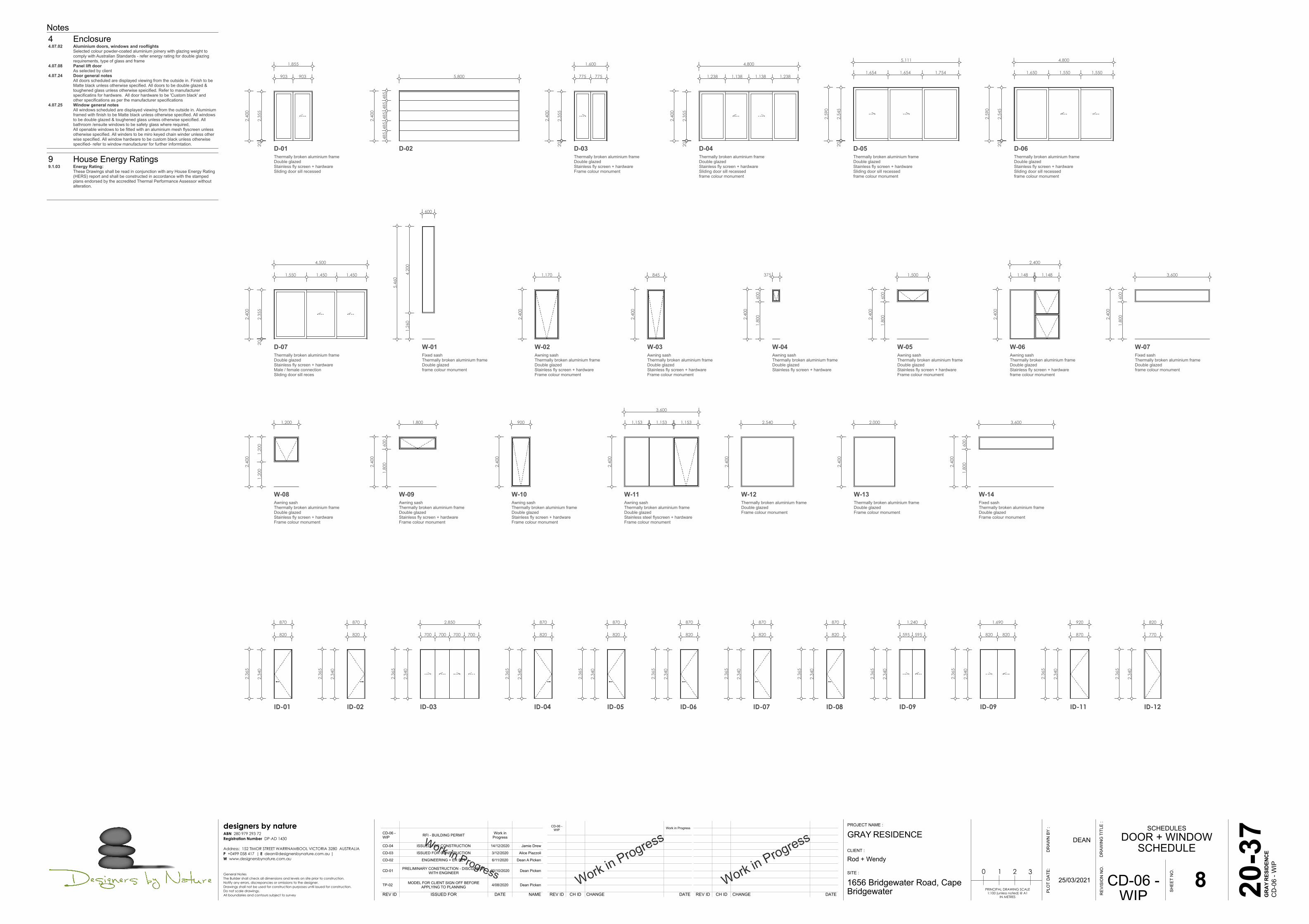
Notes4 Enclosure4.07.02 Aluminium doors, windows and rooflights
Selected colour powder-coated aluminium joinery with glazing weight tocomply with Australian Standards - refer energy rating for double glazingrequirements, type of glass and frame
4.07.08 Panel lift doorAs selected by client
4.07.24 Door general notesAll doors scheduled are displayed viewing from the outside in. Finish to beMatte black unless otherwise specified. All doors to be double glazed &toughened glass unless otherwise speicified. Refer to manufacturerspecificatins for hardware. All door hardware to be 'Custom black' andother specifications as per the manufacturer specifications
4.07.25 Window general notesAll windows scheduled are displayed viewing from the outside in. Aluminiumframed with finish to be Matte black unless otherwise specified. All windowsto be double glazed & toughened glass unless otherwise speicified. Allbathroom /ensuite windows to be safety glass where required,All openable windows to be fitted with an aluminium mesh flyscreen unlessotherwise specified. All winders to be miro keyed chain winder unless otherwise specified. All window hardware to be custom black unless otherwisespecified- refer to window manufacturer for further informtation.
9 House Energy Ratings9.1.03 Energy Rating:
These Drawings shall be read in conjunction with any House Energy Rating(HERS) report and shall be constructed in accordance with the stampedplans endorsed by the accredited Thermal Performance Assessor withoutalteration.

Work in Progress
Work in Progress
REV ID CH ID CHANGE DATE REV ID CH ID CHANGE DATE
CD-06 -WIP Work in Progress
Work in Progress
REV ID ISSUED FOR DATE NAME
TP-02
TP-03
CD-01
CD-02
CD-03
CD-04
CD-06 -WIP
MODEL FOR CLIENT SIGN OFF BEFOREAPPLYING TO PLANNING
PLANNING APPLICATION
PRELIMINARY CONSTRUCTION - DISCUSSIONWITH ENGINEER
ENGINEERING + ER SET
ISSUED FOR CONSTRUCTION
ISSUED FOR CONSTRUCTION
RFI - BUILDING PERMIT
4/08/2020
13/09/2020
20/10/2020
6/11/2020
3/12/2020
14/12/2020
Work inProgress
Dean Picken
Dean Picken
Dean Picken
Dean A Picken
Alice Piazzoli
Jamie Drew
PLO
T D
ATE:
DR
AWN
BY
:
GRAY RESIDENCE
1656 Bridgewater Road, CapeBridgewater
Rod + Wendy
COUNCIL DOCUMENTSSHADOW DIAGRAMS
PROJECT NAME :
DR
AWIN
G T
ITLE
:
CLIENT :
SITE :
20-3
7
SHEE
T N
O.
9
REV
ISIO
N N
O.
CD-06 -WIP
DEAN
25/03/2021PRINCIPAL DRAWING SCALE
1:100 (unless noted) @ A1IN METRES
0 1 2 3
GRA
Y RE
SIDE
NCE
CD
-06
- WIP
designers by natureABN 280 979 293 72Registration Number DP-AD 1430
Address: 152 TIMOR STREET WARRNAMBOOL VICTORIA 3280 AUSTRALIAP +0499 058 417 | E [email protected] |W www.designersbynature.com.au
General NotesThe Builder shall check all dimensions and levels on site prior to construction.Notify any errors, discrepancies or omissions to the designer.Drawings shall not be used for construction purposes until issued for construction.Do not scale drawings.All boundaries and contours subject to survey
N
9AM Proposed September 21N.T.S 3PM Proposed September 21
N.T.S
9AM Existing September 21N.T.S 12PM Existing September 21
N.T.S 3PM Existing September 21N.T.S
12PM Proposed September 21N.T.S

Work in Progress
Work in Progress
REV ID CH ID CHANGE DATE REV ID CH ID CHANGE DATE
CD-06 -WIP Work in Progress
Work in Progress
REV ID ISSUED FOR DATE NAMETP-03
CD-01
CD-02
CD-03
CD-04
CD-05
CD-06 -WIP
PLANNING APPLICATION
PRELIMINARY CONSTRUCTION - DISCUSSIONWITH ENGINEER
ENGINEERING + ER SET
ISSUED FOR CONSTRUCTION
ISSUED FOR CONSTRUCTION
RFI - BUILDING PERMIT
RFI - BUILDING PERMIT
13/09/2020
20/10/2020
6/11/2020
3/12/2020
14/12/2020
12/02/2021
Work inProgress
Dean Picken
Dean Picken
Dean A Picken
Alice Piazzoli
Jamie Drew
Alice Piazzoli
PLO
T D
ATE:
DR
AWN
BY
:
GRAY RESIDENCE
1656 Bridgewater Road, CapeBridgewater
Rod + Wendy
VIEWSPERSPECTIVES
PROJECT NAME :
DR
AWIN
G T
ITLE
:
CLIENT :
SITE :
20-3
7
SHEE
T N
O.
10
REV
ISIO
N N
O.
CD-06 -WIP
DEAN
25/03/2021PRINCIPAL DRAWING SCALE
1:100 (unless noted) @ A1IN METRES
0 1 2 3
GRA
Y RE
SIDE
NCE
CD
-06
- WIP
designers by natureABN 280 979 293 72Registration Number DP-AD 1430
Address: 152 TIMOR STREET WARRNAMBOOL VICTORIA 3280 AUSTRALIAP +0499 058 417 | E [email protected] |W www.designersbynature.com.au
General NotesThe Builder shall check all dimensions and levels on site prior to construction.Notify any errors, discrepancies or omissions to the designer.Drawings shall not be used for construction purposes until issued for construction.Do not scale drawings.All boundaries and contours subject to survey
01 Entry ViewN.T.S
02 CourtyardN.T.S05 Bed 1 View
N.T.S
07 Balcony ViewN.T.S
04 Rear ViewN.T.S
08 Street ViewN.T.S
03 Kitchen ViewN.T.S
06 Rumpus Room ViewN.T.S