Embed Size (px)
Citation preview

RESI®
RESI Informatik & Automation
GmbH
Date: 7.1.2013 Customer: Pages
Version: 3.1 Title: RESI-MBUS-MODBUS Manual
21 Edited by: DI HC Sigl Reviewed by: DI HC Sigl
Project: Reviewed by: -
. Prop
rieta
ry
dat
a,
com
pany
c
onfid
entia
l.
All
rig
hts
re
serv
ed.
Con
fié
à
titr
e d
e s
ecre
t
d'en
trepr
ise.
To
us
droi
ts
rés
ervé
s.C
omun
icad
o co
mo
segr
edo
empr
esar
ial.
Res
erva
dos
todo
s os
di
reito
s.C
onfid
ado
com
o se
cret
o in
dust
rial.
Nos
res
erva
mos
tod
os lo
s de
rech
os.
.
. Wei
terg
abe
sow
ie
Verv
ielfä
ltigun
g d
iese
r U
nter
lage
,
Ver-
wer
tung
un
d M
ittei
lung
ih
res
Inha
lts n
icht
ges
tatte
t, so
wei
tni
cht
aus
drüc
klich
zu
gest
ande
n.
Zuw
ider
hand
lung
en
ver-
pflic
hten
zu
Scha
dene
rsat
z.
Alle
Rec
hte
vorb
ehal
ten,
ins
be-
sond
ere
für
den
Fall
der
Pate
nter
teilu
ng o
der
GM
-Ein
tragu
ng.
.
RESI-MBUS-MODBUS
Manual
Great care has been taken in the creation of the text, illustrations and program examples in this manual. The editors and publishers accept
no responsibility for any inadvertent omission of entries or for typographical or other errors herein. Nor can they be held responsible
or liable for consequences arising from any errors herein. This manual is subject to copyright law. All rights are reserved.
This manual may not be copied in part or whole in any form including electronic media without the written consent of RESI. Neither may it be
transferred in any other language suitable for machines or data processing facilities. Also rights for reproduction through lecture, radio
or television transmission are reserved. This documentation and the accompanying software are copyrighted
by RESI. © Copyright 2005 – 2013 by RESI Informatik & Automation GmbH
‘Windows’ and ‘Microsoft’ are registered trademarks of Microsoft
Corporation. ‘Pentium’ is a registered trademark of Intel Corporation. ‘Adobe’, ‘Acrobat’, ‘Acrobat Reader’ and the ‘Adobe Logo’ are
registered trademarks of Adobe System Incorporated. All other trademarks mentioned and shown in the text are trademarks
of their owners and are patented that way
RESI®
Title: RESI-MBUS-MODBUS Manual Date Page of
7.1.2013 2 21
. Prop
rieta
ry
dat
a,
com
pany
c
onfid
entia
l.
All
rig
hts
re
serv
ed.
Con
fié
à
titr
e d
e s
ecre
t
d'en
trepr
ise.
To
us
droi
ts
rés
ervé
s.C
omun
icad
o co
mo
segr
edo
empr
esar
ial.
Res
erva
dos
todo
s os
di
reito
s.C
onfid
ado
com
o se
cret
o in
dust
rial.
Nos
res
erva
mos
tod
os lo
s de
rech
os.
.
. Wei
terg
abe
sow
ie
Verv
ielfä
ltigun
g d
iese
r U
nter
lage
,
Ver-
wer
tung
un
d M
ittei
lung
ih
res
Inha
lts n
icht
ges
tatte
t, so
wei
tni
cht
aus
drüc
klich
zu
gest
ande
n.
Zuw
ider
hand
lung
en
ver-
pflic
hten
zu
Scha
dene
rsat
z.
Alle
Rec
hte
vorb
ehal
ten,
ins
be-
sond
ere
für
den
Fall
der
Pate
nter
teilu
ng o
der
GM
-Ein
tragu
ng.
.
1 History
Date Editor Description 29.07.08 D. Sudy First Version 01.08.08 Ing. O. Reisky Review 22.08.08 Ing. O. Reisky Changed value count of RESI-MBUS2-MODBUS form 200 to 500 07.10.08 Ing. O. Reisky Version 01.01.00:
Implemented secondary addressing, increased register count per modbus telegram from 50 to 100 � affected firmware versions: 3.1.0 (RESI-MBUS-MODBUS) / 1.1.0 (RESI-MBUS2-MODBUS) and higher
13.01.10 DI HC Sigl Adoption to new converter case 7.1.13 DI HC Sigl Final adoption to new converter
RESI®
Title: RESI-MBUS-MODBUS Manual Date Page of
7.1.2013 3 21
. Prop
rieta
ry
dat
a,
com
pany
c
onfid
entia
l.
All
rig
hts
re
serv
ed.
Con
fié
à
titr
e d
e s
ecre
t
d'en
trepr
ise.
To
us
droi
ts
rés
ervé
s.C
omun
icad
o co
mo
segr
edo
empr
esar
ial.
Res
erva
dos
todo
s os
di
reito
s.C
onfid
ado
com
o se
cret
o in
dust
rial.
Nos
res
erva
mos
tod
os lo
s de
rech
os.
.
. Wei
terg
abe
sow
ie
Verv
ielfä
ltigun
g d
iese
r U
nter
lage
,
Ver-
wer
tung
un
d M
ittei
lung
ih
res
Inha
lts n
icht
ges
tatte
t, so
wei
tni
cht
aus
drüc
klich
zu
gest
ande
n.
Zuw
ider
hand
lung
en
ver-
pflic
hten
zu
Scha
dene
rsat
z.
Alle
Rec
hte
vorb
ehal
ten,
ins
be-
sond
ere
für
den
Fall
der
Pate
nter
teilu
ng o
der
GM
-Ein
tragu
ng.
.
2 Content
RESI-MBUS-MODBUS........................................................................................................................................................ 1
MANUAL............................................................................................................................................................................... 1
1 HISTORY ........................................................................................................................................................................... 2
2 CONTENT .......................................................................................................................................................................... 3
3 GENERAL INFORMATION ........................................................................................................................................... 4
4 CONNECTION DIAGRAMM.......................................................................................................................................... 5
4.1 ASSEMBLING ............................................................................................................................................................. 5
4.2 CONNECTION DIAGRAM ............................................................................................................................................. 6
4.3 WIRING DIAGRAM ...................................................................................................................................................... 8
5 FUNCTIONAL DESCRIPTION ...................................................................................................................................... 9
5.1 FIELD OF APPLICATIONS ............................................................................................................................................. 9
5.2 OPERATION .............................................................................................................................................................. 11
5.3 MODBUS INTERFACE ................................................................................................................................................ 14
5.4 METER-BUS INTERFACE........................................................................................................................................... 18
6 SPECIFICATIONS .......................................................................................................................................................... 19
6.1 DIMENSIONS ............................................................................................................................................................ 19
6.2 ELECTRICAL DATA .................................................................................................................................................. 21
RESI®
Title: RESI-MBUS-MODBUS Manual Date Page of
7.1.2013 4 21
. Prop
rieta
ry
dat
a,
com
pany
c
onfid
entia
l.
All
rig
hts
re
serv
ed.
Con
fié
à
titr
e d
e s
ecre
t
d'en
trepr
ise.
To
us
droi
ts
rés
ervé
s.C
omun
icad
o co
mo
segr
edo
empr
esar
ial.
Res
erva
dos
todo
s os
di
reito
s.C
onfid
ado
com
o se
cret
o in
dust
rial.
Nos
res
erva
mos
tod
os lo
s de
rech
os.
.
. Wei
terg
abe
sow
ie
Verv
ielfä
ltigun
g d
iese
r U
nter
lage
,
Ver-
wer
tung
un
d M
ittei
lung
ih
res
Inha
lts n
icht
ges
tatte
t, so
wei
tni
cht
aus
drüc
klich
zu
gest
ande
n.
Zuw
ider
hand
lung
en
ver-
pflic
hten
zu
Scha
dene
rsat
z.
Alle
Rec
hte
vorb
ehal
ten,
ins
be-
sond
ere
für
den
Fall
der
Pate
nter
teilu
ng o
der
GM
-Ein
tragu
ng.
.
3 General Information
Since the data from RESI-MBUS-MODBUS converters can be read from any Modbus-Master (automated control, visualisation system etc...) a very broad range of applications becomes possible. For instance data from a heat meter can be easily represented on a mimic display. Each MBUS-MODBUS converter module can read the data from up to 8 / 24 Meter bus unit loads ( 1 unit load corresponds to 1,5 mA current consumption of one participant). Thus maximal 8 / 24 devices each one unit load can be connected to one MBUS-MODBUS Converter. The current consumption of a device can be seen from the respective data sheet. The values to be read are freely configurable and are automatically queryed in selectable periods of time.
• Meter-Bus interface for a maximum 8 / 24 unit loads (1,5 mA)
• Meter-Bus interface: 300 up to 38400 bps, 8 Data bits, even Parity, 1 Stop bit
• Meter-Bus and Modbus interface electrically isolated
• Modbus interface: RS232 or RS485, 9600 up to 57600 bps, 8 Data bits, none Parity, 1 Stop bit
• Modbus adress and query timeout are configurable
• Configuration of up to 100 / 500 Meter-Bus values
• 5 different data types for value representation in Modbus registers
• 24V DC power supply
Type Description Voltage Weight
RESI-MBUS-MODBUS
Meter-Bus to Modbus Converter with RS232 or RS485 interface supporting 8 meters and 100 configurable values, DIP switch for setttings
24 V= 90 g
RESI-MBUS2-MODBUS
Meter-Bus to Modbus Converter with RS232 or RS485 interface supporting 24 meters and 500 configurable values, DIP switch for settings
24 V= 90 g
Technical Data Supply voltage 24 V= operating temperature -40...85 °C Power consumption 1 VA Toleratable Humidity 10...90 % rH non-
condensing Degree of protection IP20 (EN 60529) Modbus Interface Protection Class IP20 Protocol Modbus/RTU Type RS232 or RS485 9600 to 57600 / 8 / N / 1 Dimensions LxHxD 17,5 x 58 x 90 Meter-Bus Interface max. unit loads 8 300 to 38400 / 8 / E / 1 Factory settings Modbus adress 255 Modbus baud rate: 19200 Clamps M-Bus baud rate: 300 max. connector cross-section
2,5 mm² rigid
1,5 mm² flexible CE conformity Yes IT Accessories
RESI-MODBUS-Configurator
Configuration software for RESI Modbus devices
RESI®
Title: RESI-MBUS-MODBUS Manual Date Page of
7.1.2013 5 21
. Prop
rieta
ry
dat
a,
com
pany
c
onfid
entia
l.
All
rig
hts
re
serv
ed.
Con
fié
à
titr
e d
e s
ecre
t
d'en
trepr
ise.
To
us
droi
ts
rés
ervé
s.C
omun
icad
o co
mo
segr
edo
empr
esar
ial.
Res
erva
dos
todo
s os
di
reito
s.C
onfid
ado
com
o se
cret
o in
dust
rial.
Nos
res
erva
mos
tod
os lo
s de
rech
os.
.
. Wei
terg
abe
sow
ie
Verv
ielfä
ltigun
g d
iese
r U
nter
lage
,
Ver-
wer
tung
un
d M
ittei
lung
ih
res
Inha
lts n
icht
ges
tatte
t, so
wei
tni
cht
aus
drüc
klich
zu
gest
ande
n.
Zuw
ider
hand
lung
en
ver-
pflic
hten
zu
Scha
dene
rsat
z.
Alle
Rec
hte
vorb
ehal
ten,
ins
be-
sond
ere
für
den
Fall
der
Pate
nter
teilu
ng o
der
GM
-Ein
tragu
ng.
.
4 Connection diagramm
4.1 Assembling
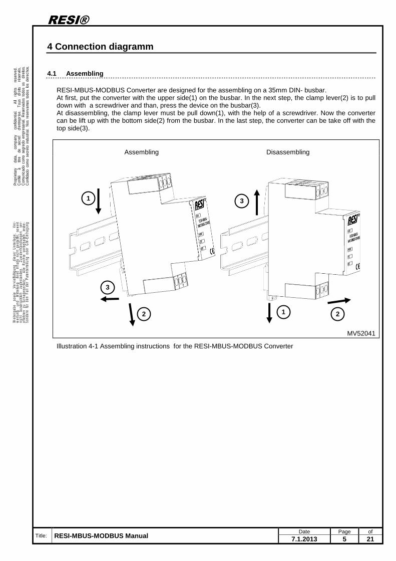
RESI-MBUS-MODBUS Converter are designed for the assembling on a 35mm DIN- busbar. At first, put the converter with the upper side(1) on the busbar. In the next step, the clamp lever(2) is to pull down with a screwdriver and than, press the device on the busbar(3). At disassembling, the clamp lever must be pull down(1), with the help of a screwdriver. Now the converter can be lift up with the bottom side(2) from the busbar. In the last step, the converter can be take off with the top side(3).
Assembling Disassembling
MV52041
Illustration 4-1 Assembling instructions for the RESI-MBUS-MODBUS Converter
1
2
3
1 2
3
RESI®
Title: RESI-MBUS-MODBUS Manual Date Page of
7.1.2013 6 21
. Prop
rieta
ry
dat
a,
com
pany
c
onfid
entia
l.
All
rig
hts
re
serv
ed.
Con
fié
à
titr
e d
e s
ecre
t
d'en
trepr
ise.
To
us
droi
ts
rés
ervé
s.C
omun
icad
o co
mo
segr
edo
empr
esar
ial.
Res
erva
dos
todo
s os
di
reito
s.C
onfid
ado
com
o se
cret
o in
dust
rial.
Nos
res
erva
mos
tod
os lo
s de
rech
os.
.
. Wei
terg
abe
sow
ie
Verv
ielfä
ltigun
g d
iese
r U
nter
lage
,
Ver-
wer
tung
un
d M
ittei
lung
ih
res
Inha
lts n
icht
ges
tatte
t, so
wei
tni
cht
aus
drüc
klich
zu
gest
ande
n.
Zuw
ider
hand
lung
en
ver-
pflic
hten
zu
Scha
dene
rsat
z.
Alle
Rec
hte
vorb
ehal
ten,
ins
be-
sond
ere
für
den
Fall
der
Pate
nter
teilu
ng o
der
GM
-Ein
tragu
ng.
.
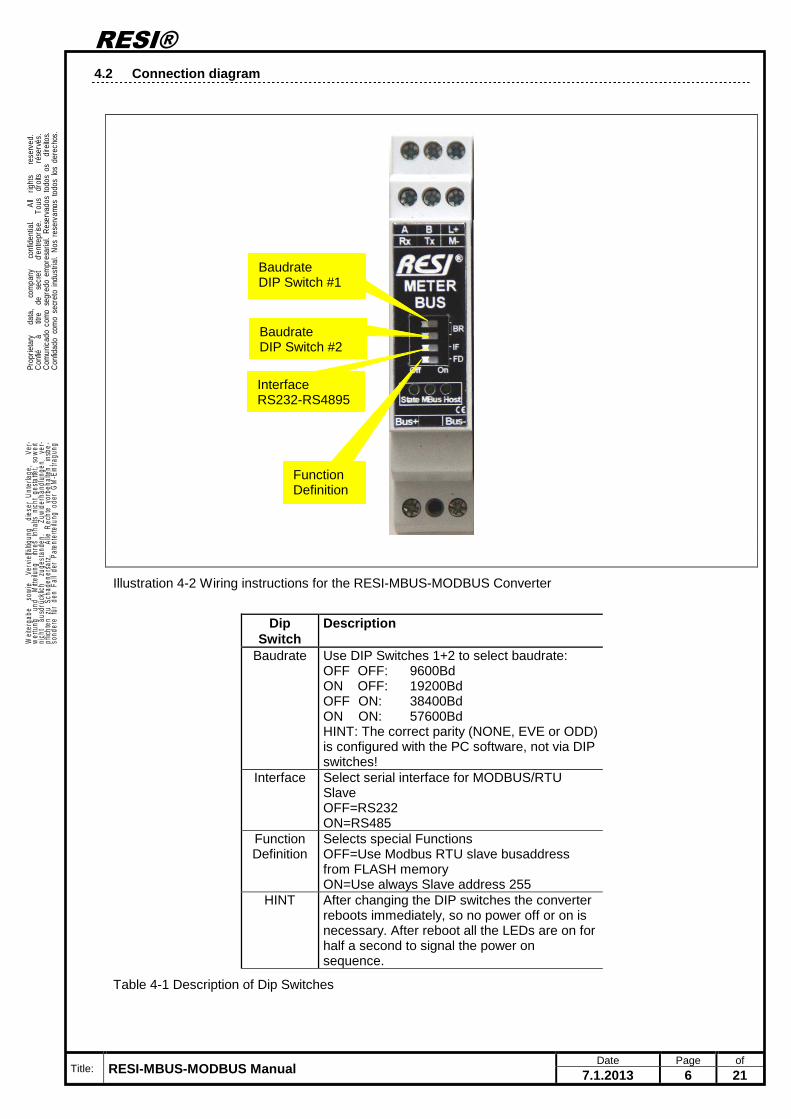
4.2 Connection diagram
Illustration 4-2 Wiring instructions for the RESI-MBUS-MODBUS Converter
Dip
Switch Description
Baudrate Use DIP Switches 1+2 to select baudrate: OFF OFF: 9600Bd ON OFF: 19200Bd OFF ON: 38400Bd ON ON: 57600Bd HINT: The correct parity (NONE, EVE or ODD) is configured with the PC software, not via DIP switches!
Interface Select serial interface for MODBUS/RTU Slave OFF=RS232 ON=RS485
Function Definition
Selects special Functions OFF=Use Modbus RTU slave busaddress from FLASH memory ON=Use always Slave address 255
HINT After changing the DIP switches the converter reboots immediately, so no power off or on is necessary. After reboot all the LEDs are on for half a second to signal the power on sequence.
Table 4-1 Description of Dip Switches
Baudrate DIP Switch #1
Baudrate DIP Switch #2
Interface RS232-RS4895
Function Definition
RESI®
Title: RESI-MBUS-MODBUS Manual Date Page of
7.1.2013 7 21
. Prop
rieta
ry
dat
a,
com
pany
c
onfid
entia
l.
All
rig
hts
re
serv
ed.
Con
fié
à
titr
e d
e s
ecre
t
d'en
trepr
ise.
To
us
droi
ts
rés
ervé
s.C
omun
icad
o co
mo
segr
edo
empr
esar
ial.
Res
erva
dos
todo
s os
di
reito
s.C
onfid
ado
com
o se
cret
o in
dust
rial.
Nos
res
erva
mos
tod
os lo
s de
rech
os.
.
. Wei
terg
abe
sow
ie
Verv
ielfä
ltigun
g d
iese
r U
nter
lage
,
Ver-
wer
tung
un
d M
ittei
lung
ih
res
Inha
lts n
icht
ges
tatte
t, so
wei
tni
cht
aus
drüc
klich
zu
gest
ande
n.
Zuw
ider
hand
lung
en
ver-
pflic
hten
zu
Scha
dene
rsat
z.
Alle
Rec
hte
vorb
ehal
ten,
ins
be-
sond
ere
für
den
Fall
der
Pate
nter
teilu
ng o
der
GM
-Ein
tragu
ng.
.
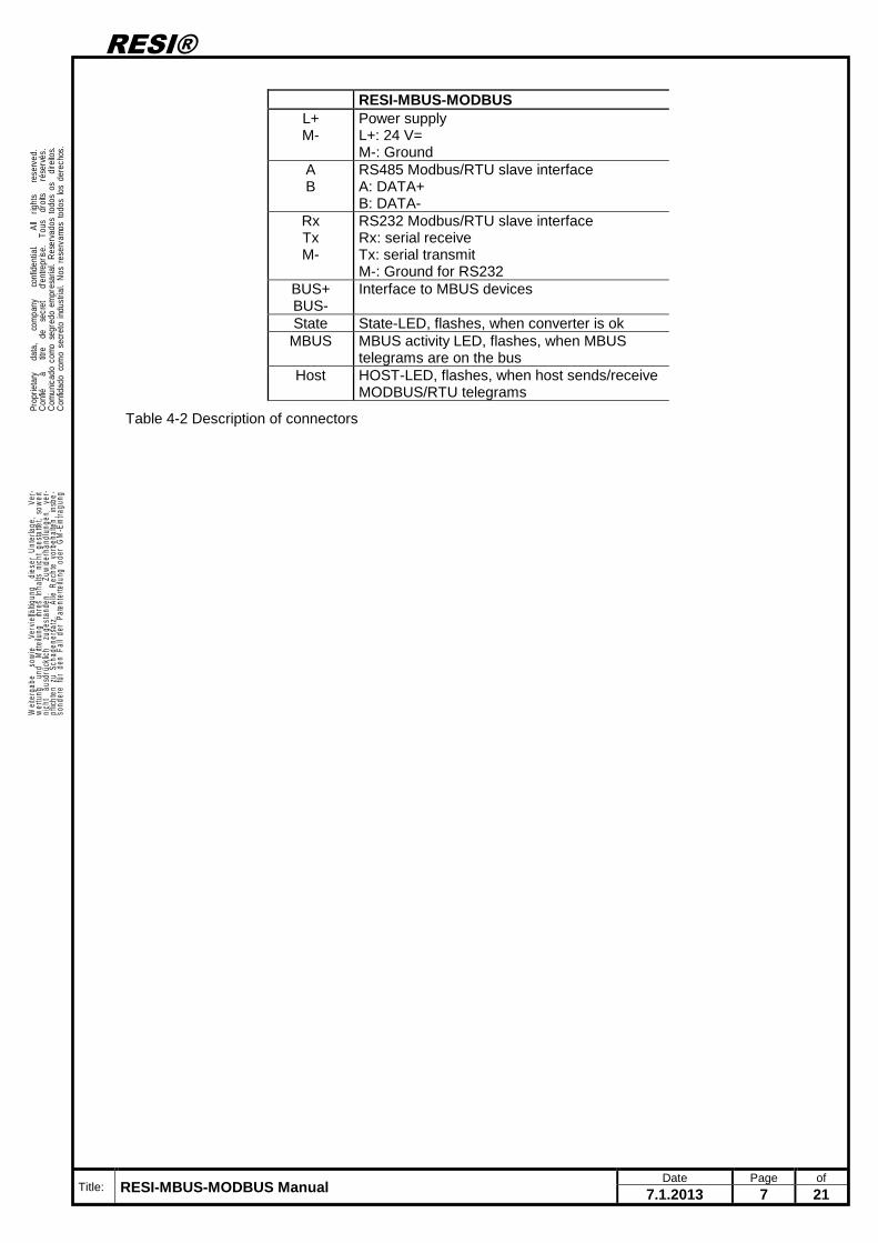
RESI-MBUS-MODBUS
L+ M-
Power supply L+: 24 V= M-: Ground
A B
RS485 Modbus/RTU slave interface A: DATA+ B: DATA-
Rx Tx M-
RS232 Modbus/RTU slave interface Rx: serial receive Tx: serial transmit M-: Ground for RS232
BUS+ BUS-
Interface to MBUS devices
State State-LED, flashes, when converter is ok MBUS MBUS activity LED, flashes, when MBUS
telegrams are on the bus Host HOST-LED, flashes, when host sends/receive
MODBUS/RTU telegrams
Table 4-2 Description of connectors
RESI®
Title: RESI-MBUS-MODBUS Manual Date Page of
7.1.2013 8 21
. Prop
rieta
ry
dat
a,
com
pany
c
onfid
entia
l.
All
rig
hts
re
serv
ed.
Con
fié
à
titr
e d
e s
ecre
t
d'en
trepr
ise.
To
us
droi
ts
rés
ervé
s.C
omun
icad
o co
mo
segr
edo
empr
esar
ial.
Res
erva
dos
todo
s os
di
reito
s.C
onfid
ado
com
o se
cret
o in
dust
rial.
Nos
res
erva
mos
tod
os lo
s de
rech
os.
.
. Wei
terg
abe
sow
ie
Verv
ielfä
ltigun
g d
iese
r U
nter
lage
,
Ver-
wer
tung
un
d M
ittei
lung
ih
res
Inha
lts n
icht
ges
tatte
t, so
wei
tni
cht
aus
drüc
klich
zu
gest
ande
n.
Zuw
ider
hand
lung
en
ver-
pflic
hten
zu
Scha
dene
rsat
z.
Alle
Rec
hte
vorb
ehal
ten,
ins
be-
sond
ere
für
den
Fall
der
Pate
nter
teilu
ng o
der
GM
-Ein
tragu
ng.
.
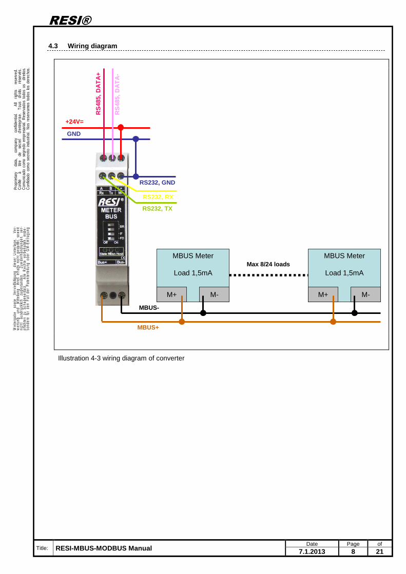
4.3 Wiring diagram
MBUS+
MBUS-
+24V=
GND
RS
485,
DA
TA
+
RS
485,
DA
TA
-
RS232, TX
RS232, RX
RS232, GND
MBUS Meter
Load 1,5mA
M+ M-
MBUS Meter
Load 1,5mA
M+ M-
Max 8/24 loads
Illustration 4-3 wiring diagram of converter
RESI®
Title: RESI-MBUS-MODBUS Manual Date Page of
7.1.2013 9 21
. Prop
rieta
ry
dat
a,
com
pany
c
onfid
entia
l.
All
rig
hts
re
serv
ed.
Con
fié
à
titr
e d
e s
ecre
t
d'en
trepr
ise.
To
us
droi
ts
rés
ervé
s.C
omun
icad
o co
mo
segr
edo
empr
esar
ial.
Res
erva
dos
todo
s os
di
reito
s.C
onfid
ado
com
o se
cret
o in
dust
rial.
Nos
res
erva
mos
tod
os lo
s de
rech
os.
.
. Wei
terg
abe
sow
ie
Verv
ielfä
ltigun
g d
iese
r U
nter
lage
,
Ver-
wer
tung
un
d M
ittei
lung
ih
res
Inha
lts n
icht
ges
tatte
t, so
wei
tni
cht
aus
drüc
klich
zu
gest
ande
n.
Zuw
ider
hand
lung
en
ver-
pflic
hten
zu
Scha
dene
rsat
z.
Alle
Rec
hte
vorb
ehal
ten,
ins
be-
sond
ere
für
den
Fall
der
Pate
nter
teilu
ng o
der
GM
-Ein
tragu
ng.
.
5 Functional Description
RESI-MBUS-MODBUS Converter automatically read out values of meters with a MBUS interface and stores the values in internal Modbus Holding registers. The converter can hold up to 100/500 MODBUS 16 bit values. A host system can read out asynchronously the stored values via MODBUS RTU master functionality. The physical connection is done via RS232 or via RS485 interface. After switching on the power supply, the converter checks for a valid configuration and initializes all registers to Zero. If there is no valid configuration or an other error occurred, the state indicator flahes every second, oherwise if startup was successful it flashes every two seconds. The power on sequence is signalled with a short flash of all the LEDs in the converter. To configure the meters, please use our free software MODBUSConfigurator.exe, which you can download from our homepage www.RESI.cc. Please refer to our online help system for more details about the configuration process of meters and the mapping to MBUS registers. Use this link: http://www.resi.cc/resiwiki/index.php/MBUS_products
5.1 Field of applications
This chapter shows typical applications, where our converter can be used.
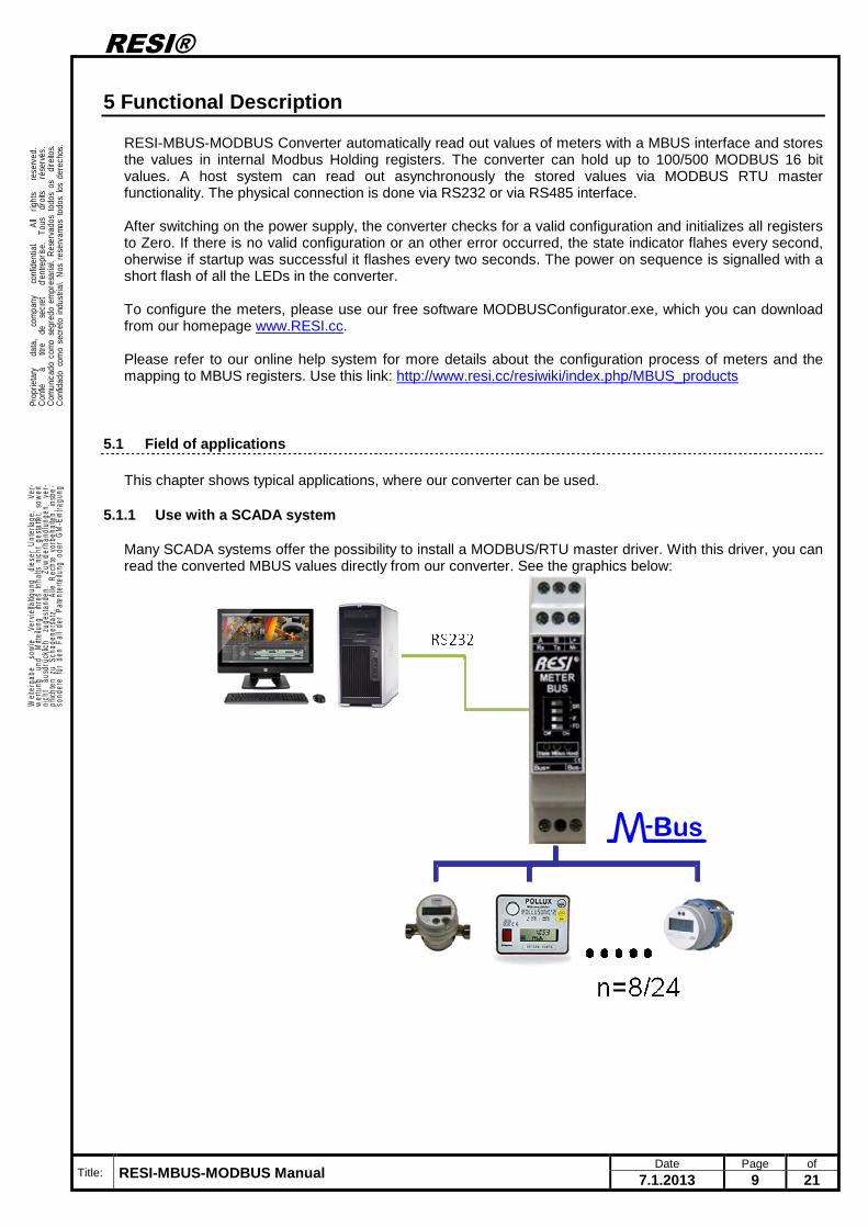
5.1.1 Use with a SCADA system
Many SCADA systems offer the possibility to install a MODBUS/RTU master driver. With this driver, you can read the converted MBUS values directly from our converter. See the graphics below:
RESI®
Title: RESI-MBUS-MODBUS Manual Date Page of
7.1.2013 10 21
. Prop
rieta
ry
dat
a,
com
pany
c
onfid
entia
l.
All
rig
hts
re
serv
ed.
Con
fié
à
titr
e d
e s
ecre
t
d'en
trepr
ise.
To
us
droi
ts
rés
ervé
s.C
omun
icad
o co
mo
segr
edo
empr
esar
ial.
Res
erva
dos
todo
s os
di
reito
s.C
onfid
ado
com
o se
cret
o in
dust
rial.
Nos
res
erva
mos
tod
os lo
s de
rech
os.
.
. Wei
terg
abe
sow
ie
Verv
ielfä
ltigun
g d
iese
r U
nter
lage
,
Ver-
wer
tung
un
d M
ittei
lung
ih
res
Inha
lts n
icht
ges
tatte
t, so
wei
tni
cht
aus
drüc
klich
zu
gest
ande
n.
Zuw
ider
hand
lung
en
ver-
pflic
hten
zu
Scha
dene
rsat
z.
Alle
Rec
hte
vorb
ehal
ten,
ins
be-
sond
ere
für
den
Fall
der
Pate
nter
teilu
ng o
der
GM
-Ein
tragu
ng.
.
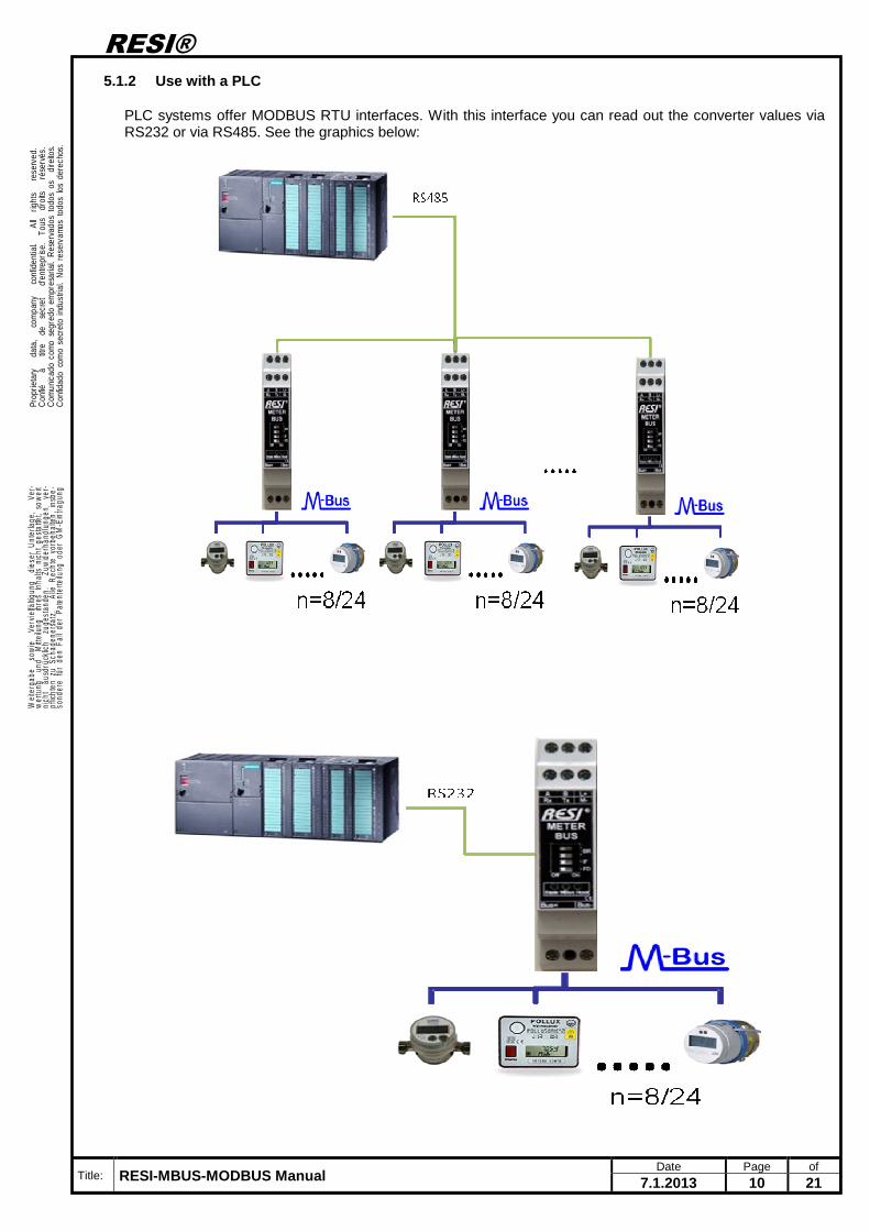
5.1.2 Use with a PLC
PLC systems offer MODBUS RTU interfaces. With this interface you can read out the converter values via RS232 or via RS485. See the graphics below:
RESI®
Title: RESI-MBUS-MODBUS Manual Date Page of
7.1.2013 11 21
. Prop
rieta
ry
dat
a,
com
pany
c
onfid
entia
l.
All
rig
hts
re
serv
ed.
Con
fié
à
titr
e d
e s
ecre
t
d'en
trepr
ise.
To
us
droi
ts
rés
ervé
s.C
omun
icad
o co
mo
segr
edo
empr
esar
ial.
Res
erva
dos
todo
s os
di
reito
s.C
onfid
ado
com
o se
cret
o in
dust
rial.
Nos
res
erva
mos
tod
os lo
s de
rech
os.
.
. Wei
terg
abe
sow
ie
Verv
ielfä
ltigun
g d
iese
r U
nter
lage
,
Ver-
wer
tung
un
d M
ittei
lung
ih
res
Inha
lts n
icht
ges
tatte
t, so
wei
tni
cht
aus
drüc
klich
zu
gest
ande
n.
Zuw
ider
hand
lung
en
ver-
pflic
hten
zu
Scha
dene
rsat
z.
Alle
Rec
hte
vorb
ehal
ten,
ins
be-
sond
ere
für
den
Fall
der
Pate
nter
teilu
ng o
der
GM
-Ein
tragu
ng.
.
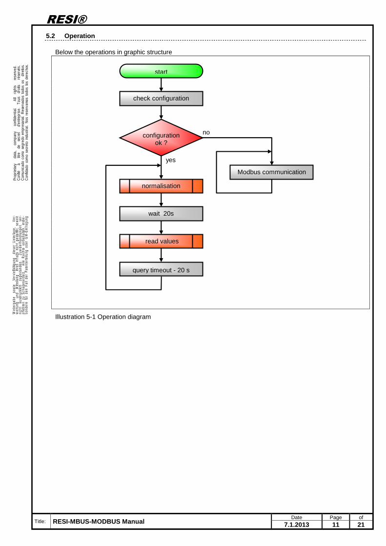
5.2 Operation
Below the operations in graphic structure
Illustration 5-1 Operation diagram
start
check configuration
configuration ok ?
yes
no
Modbus communication
normalisation
read values
wait 20s
query timeout - 20 s
RESI®
Title: RESI-MBUS-MODBUS Manual Date Page of
7.1.2013 12 21
. Prop
rieta
ry
dat
a,
com
pany
c
onfid
entia
l.
All
rig
hts
re
serv
ed.
Con
fié
à
titr
e d
e s
ecre
t
d'en
trepr
ise.
To
us
droi
ts
rés
ervé
s.C
omun
icad
o co
mo
segr
edo
empr
esar
ial.
Res
erva
dos
todo
s os
di
reito
s.C
onfid
ado
com
o se
cret
o in
dust
rial.
Nos
res
erva
mos
tod
os lo
s de
rech
os.
.
. Wei
terg
abe
sow
ie
Verv
ielfä
ltigun
g d
iese
r U
nter
lage
,
Ver-
wer
tung
un
d M
ittei
lung
ih
res
Inha
lts n
icht
ges
tatte
t, so
wei
tni
cht
aus
drüc
klich
zu
gest
ande
n.
Zuw
ider
hand
lung
en
ver-
pflic
hten
zu
Scha
dene
rsat
z.
Alle
Rec
hte
vorb
ehal
ten,
ins
be-
sond
ere
für
den
Fall
der
Pate
nter
teilu
ng o
der
GM
-Ein
tragu
ng.
.
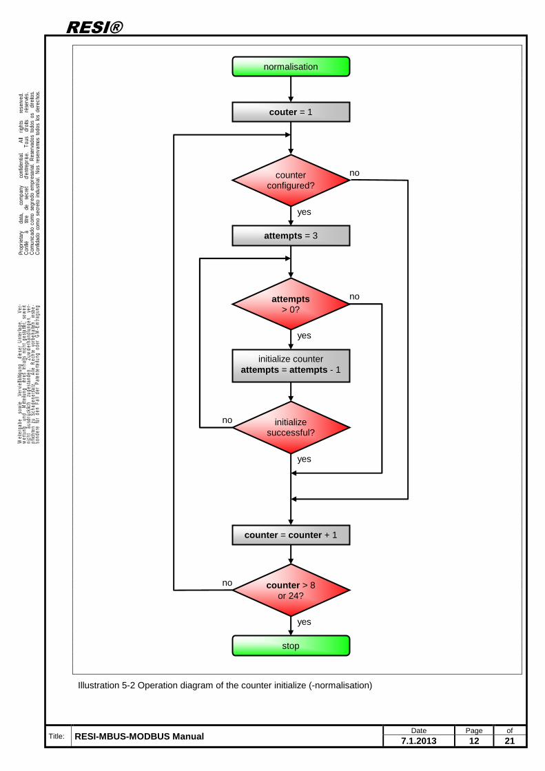
Illustration 5-2 Operation diagram of the counter initialize (-normalisation)
normalisation
couter = 1
attempts = 3
counter configured?
yes
no
initialize counter attempts = attempts - 1
initialize successful?
yes
no
attempts > 0?
yes
no
counter = counter + 1
counter > 8 or 24?
yes
no
stop
RESI®
Title: RESI-MBUS-MODBUS Manual Date Page of
7.1.2013 13 21
. Prop
rieta
ry
dat
a,
com
pany
c
onfid
entia
l.
All
rig
hts
re
serv
ed.
Con
fié
à
titr
e d
e s
ecre
t
d'en
trepr
ise.
To
us
droi
ts
rés
ervé
s.C
omun
icad
o co
mo
segr
edo
empr
esar
ial.
Res
erva
dos
todo
s os
di
reito
s.C
onfid
ado
com
o se
cret
o in
dust
rial.
Nos
res
erva
mos
tod
os lo
s de
rech
os.
.
. Wei
terg
abe
sow
ie
Verv
ielfä
ltigun
g d
iese
r U
nter
lage
,
Ver-
wer
tung
un
d M
ittei
lung
ih
res
Inha
lts n
icht
ges
tatte
t, so
wei
tni
cht
aus
drüc
klich
zu
gest
ande
n.
Zuw
ider
hand
lung
en
ver-
pflic
hten
zu
Scha
dene
rsat
z.
Alle
Rec
hte
vorb
ehal
ten,
ins
be-
sond
ere
für
den
Fall
der
Pate
nter
teilu
ng o
der
GM
-Ein
tragu
ng.
.
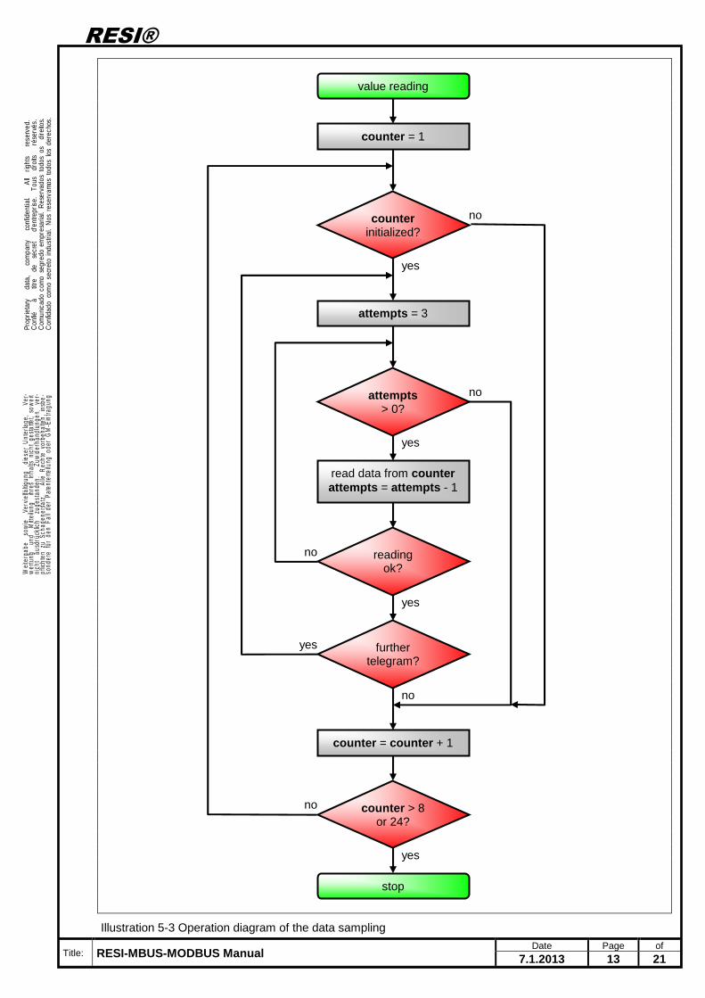
Illustration 5-3 Operation diagram of the data sampling
value reading
counter = 1
attempts = 3
counter initialized?
yes
no
read data from counter attempts = attempts - 1
reading ok?
yes
no
attempts > 0?
yes
no
counter = counter + 1
counter > 8 or 24?
yes
no
stop
further telegram?
no
yes
RESI®
Title: RESI-MBUS-MODBUS Manual Date Page of
7.1.2013 14 21
. Prop
rieta
ry
dat
a,
com
pany
c
onfid
entia
l.
All
rig
hts
re
serv
ed.
Con
fié
à
titr
e d
e s
ecre
t
d'en
trepr
ise.
To
us
droi
ts
rés
ervé
s.C
omun
icad
o co
mo
segr
edo
empr
esar
ial.
Res
erva
dos
todo
s os
di
reito
s.C
onfid
ado
com
o se
cret
o in
dust
rial.
Nos
res
erva
mos
tod
os lo
s de
rech
os.
.
. Wei
terg
abe
sow
ie
Verv
ielfä
ltigun
g d
iese
r U
nter
lage
,
Ver-
wer
tung
un
d M
ittei
lung
ih
res
Inha
lts n
icht
ges
tatte
t, so
wei
tni
cht
aus
drüc
klich
zu
gest
ande
n.
Zuw
ider
hand
lung
en
ver-
pflic
hten
zu
Scha
dene
rsat
z.
Alle
Rec
hte
vorb
ehal
ten,
ins
be-
sond
ere
für
den
Fall
der
Pate
nter
teilu
ng o
der
GM
-Ein
tragu
ng.
.
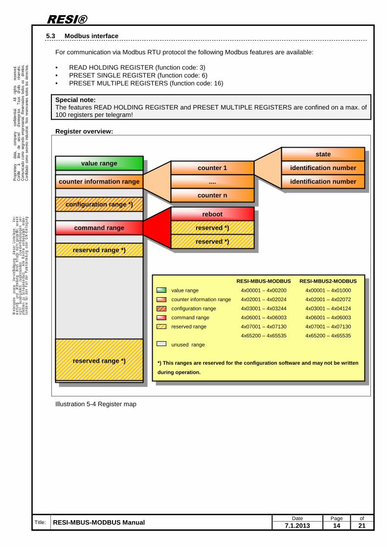
5.3 Modbus interface
For communication via Modbus RTU protocol the following Modbus features are available: • READ HOLDING REGISTER (function code: 3) • PRESET SINGLE REGISTER (function code: 6) • PRESET MULTIPLE REGISTERS (function code: 16) Special note: The features READ HOLDING REGISTER and PRESET MULTIPLE REGISTERS are confined on a max. of 100 registers per telegram! Register overview:
Illustration 5-4 Register map
value range
counter information range
configuration range *)
command range
reserved range *)
reserved range *)
counter 1
....
counter n
state
identification number
identification number
reboot
reserved *)
reserved *)
RESI-MBUS-MODBUS RESI-MBUS2-MODBUS
value range 4x00001 – 4x00200 4x00001 – 4x01000
counter information range 4x02001 – 4x02024 4x02001 – 4x02072
configuration range 4x03001 – 4x03244 4x03001 – 4x04124
command range 4x06001 – 4x06003 4x06001 – 4x06003
reserved range 4x07001 – 4x07130 4x07001 – 4x07130
4x65200 – 4x65535 4x65200 – 4x65535
unused range
*) This ranges are reserved for the configuration s oftware and may not be written
during operation.
RESI®
Title: RESI-MBUS-MODBUS Manual Date Page of
7.1.2013 15 21
. Prop
rieta
ry
dat
a,
com
pany
c
onfid
entia
l.
All
rig
hts
re
serv
ed.
Con
fié
à
titr
e d
e s
ecre
t
d'en
trepr
ise.
To
us
droi
ts
rés
ervé
s.C
omun
icad
o co
mo
segr
edo
empr
esar
ial.
Res
erva
dos
todo
s os
di
reito
s.C
onfid
ado
com
o se
cret
o in
dust
rial.
Nos
res
erva
mos
tod
os lo
s de
rech
os.
.
. Wei
terg
abe
sow
ie
Verv
ielfä
ltigun
g d
iese
r U
nter
lage
,
Ver-
wer
tung
un
d M
ittei
lung
ih
res
Inha
lts n
icht
ges
tatte
t, so
wei
tni
cht
aus
drüc
klich
zu
gest
ande
n.
Zuw
ider
hand
lung
en
ver-
pflic
hten
zu
Scha
dene
rsat
z.
Alle
Rec
hte
vorb
ehal
ten,
ins
be-
sond
ere
für
den
Fall
der
Pate
nter
teilu
ng o
der
GM
-Ein
tragu
ng.
.
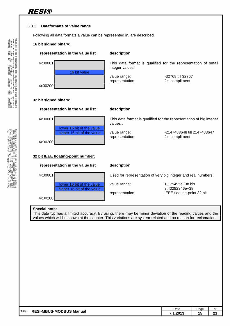
5.3.1 Dataformats of value range
Following all data formats a value can be represented in, are described. 16 bit signed binary:
representation in the value list
description
4x00001 This data format is qualified for the representation of small integer values. value range: -32768 till 32767 representation: 2’s compliment
16 bit value
4x00200 32 bit signed binary:
representation in the value list
description
4x00001 This data format is qualified for the representation of big integer values . value range: -2147483648 till 2147483647 representation: 2’s compliment
lower 16 bit of the value higher 16 bit of the value
4x00200 32 bit IEEE floating-point number:
representation in the value list
description
4x00001 Used for representation of very big integer and real numbers. value range: 1,175495e−38 bis 3,40282346e+38 representation: IEEE floating-point 32 bit
lower 16 bit of the value higher 16 bit of the value
4x00200 Special note: This data typ has a limited accuracy. By using, there may be minor deviation of the reading values and the values which will be shown at the counter. This variations are system-related and no reason for reclamation!
RESI®
Title: RESI-MBUS-MODBUS Manual Date Page of
7.1.2013 16 21
. Prop
rieta
ry
dat
a,
com
pany
c
onfid
entia
l.
All
rig
hts
re
serv
ed.
Con
fié
à
titr
e d
e s
ecre
t
d'en
trepr
ise.
To
us
droi
ts
rés
ervé
s.C
omun
icad
o co
mo
segr
edo
empr
esar
ial.
Res
erva
dos
todo
s os
di
reito
s.C
onfid
ado
com
o se
cret
o in
dust
rial.
Nos
res
erva
mos
tod
os lo
s de
rech
os.
.
. Wei
terg
abe
sow
ie
Verv
ielfä
ltigun
g d
iese
r U
nter
lage
,
Ver-
wer
tung
un
d M
ittei
lung
ih
res
Inha
lts n
icht
ges
tatte
t, so
wei
tni
cht
aus
drüc
klich
zu
gest
ande
n.
Zuw
ider
hand
lung
en
ver-
pflic
hten
zu
Scha
dene
rsat
z.
Alle
Rec
hte
vorb
ehal
ten,
ins
be-
sond
ere
für
den
Fall
der
Pate
nter
teilu
ng o
der
GM
-Ein
tragu
ng.
.
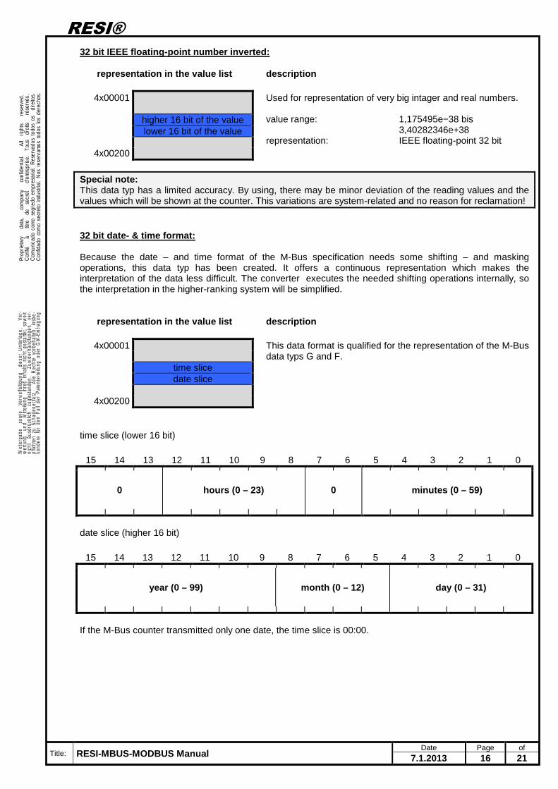
32 bit IEEE floating-point number inverted:
representation in the value list
description
4x00001 Used for representation of very big intager and real numbers. value range: 1,175495e−38 bis 3,40282346e+38 representation: IEEE floating-point 32 bit
higher 16 bit of the value lower 16 bit of the value
4x00200 Special note: This data typ has a limited accuracy. By using, there may be minor deviation of the reading values and the values which will be shown at the counter. This variations are system-related and no reason for reclamation! 32 bit date- & time format: Because the date – and time format of the M-Bus specification needs some shifting – and masking operations, this data typ has been created. It offers a continuous representation which makes the interpretation of the data less difficult. The converter executes the needed shifting operations internally, so the interpretation in the higher-ranking system will be simplified.
representation in the value list
description
4x00001 This data format is qualified for the representation of the M-Bus data typs G and F.
time slice date slice
4x00200 time slice (lower 16 bit)
15 14 13 12 11 10 9 8 7 6 5 4 3 2 1 0
0 hours (0 – 23) 0 minutes (0 – 59)
date slice (higher 16 bit)
15 14 13 12 11 10 9 8 7 6 5 4 3 2 1 0
year (0 – 99) month (0 – 12) day (0 – 31)
If the M-Bus counter transmitted only one date, the time slice is 00:00.
RESI®
Title: RESI-MBUS-MODBUS Manual Date Page of
7.1.2013 17 21
. Prop
rieta
ry
dat
a,
com
pany
c
onfid
entia
l.
All
rig
hts
re
serv
ed.
Con
fié
à
titr
e d
e s
ecre
t
d'en
trepr
ise.
To
us
droi
ts
rés
ervé
s.C
omun
icad
o co
mo
segr
edo
empr
esar
ial.
Res
erva
dos
todo
s os
di
reito
s.C
onfid
ado
com
o se
cret
o in
dust
rial.
Nos
res
erva
mos
tod
os lo
s de
rech
os.
.
. Wei
terg
abe
sow
ie
Verv
ielfä
ltigun
g d
iese
r U
nter
lage
,
Ver-
wer
tung
un
d M
ittei
lung
ih
res
Inha
lts n
icht
ges
tatte
t, so
wei
tni
cht
aus
drüc
klich
zu
gest
ande
n.
Zuw
ider
hand
lung
en
ver-
pflic
hten
zu
Scha
dene
rsat
z.
Alle
Rec
hte
vorb
ehal
ten,
ins
be-
sond
ere
für
den
Fall
der
Pate
nter
teilu
ng o
der
GM
-Ein
tragu
ng.
.
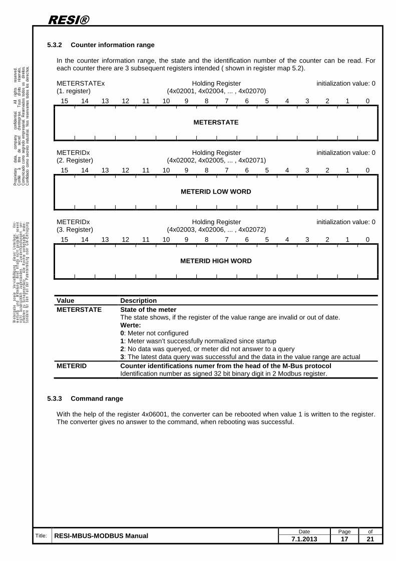
5.3.2 Counter information range
In the counter information range, the state and the identification number of the counter can be read. For each counter there are 3 subsequent registers intended ( shown in register map 5.2). METERSTATEx (1. register)
Holding Register (4x02001, 4x02004, ... , 4x02070)
initialization value: 0
15 14 13 12 11 10 9 8 7 6 5 4 3 2 1 0
METERSTATE
METERIDx (2. Register)
Holding Register (4x02002, 4x02005, ... , 4x02071)
initialization value: 0
15 14 13 12 11 10 9 8 7 6 5 4 3 2 1 0
METERID LOW WORD
METERIDx (3. Register)
Holding Register (4x02003, 4x02006, ... , 4x02072)
initialization value: 0
15 14 13 12 11 10 9 8 7 6 5 4 3 2 1 0
METERID HIGH WORD
Value Description METERSTATE State of the meter
The state shows, if the register of the value range are invalid or out of date. Werte: 0: Meter not configured 1: Meter wasn’t successfully normalized since startup 2: No data was queryed, or meter did not answer to a query 3: The latest data query was successful and the data in the value range are actual
METERID Counter identifications numer from the head of the M-Bus protocol Identification number as signed 32 bit binary digit in 2 Modbus register.
5.3.3 Command range
With the help of the register 4x06001, the converter can be rebooted when value 1 is written to the register. The converter gives no answer to the command, when rebooting was successful.
RESI®
Title: RESI-MBUS-MODBUS Manual Date Page of
7.1.2013 18 21
. Prop
rieta
ry
dat
a,
com
pany
c
onfid
entia
l.
All
rig
hts
re
serv
ed.
Con
fié
à
titr
e d
e s
ecre
t
d'en
trepr
ise.
To
us
droi
ts
rés
ervé
s.C
omun
icad
o co
mo
segr
edo
empr
esar
ial.
Res
erva
dos
todo
s os
di
reito
s.C
onfid
ado
com
o se
cret
o in
dust
rial.
Nos
res
erva
mos
tod
os lo
s de
rech
os.
.
. Wei
terg
abe
sow
ie
Verv
ielfä
ltigun
g d
iese
r U
nter
lage
,
Ver-
wer
tung
un
d M
ittei
lung
ih
res
Inha
lts n
icht
ges
tatte
t, so
wei
tni
cht
aus
drüc
klich
zu
gest
ande
n.
Zuw
ider
hand
lung
en
ver-
pflic
hten
zu
Scha
dene
rsat
z.
Alle
Rec
hte
vorb
ehal
ten,
ins
be-
sond
ere
für
den
Fall
der
Pate
nter
teilu
ng o
der
GM
-Ein
tragu
ng.
.
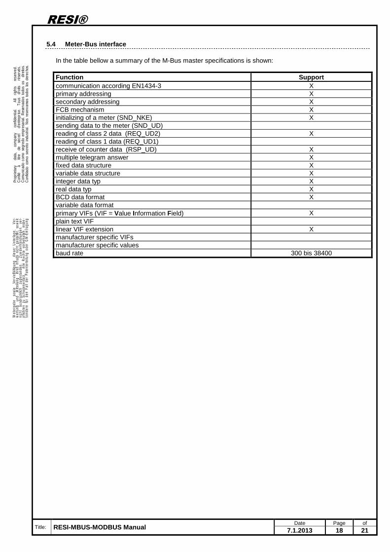
5.4 Meter-Bus interface
In the table bellow a summary of the M-Bus master specifications is shown: Function Support communication according EN1434-3 X primary addressing X secondary addressing X FCB mechanism X initializing of a meter (SND_NKE) X sending data to the meter (SND_UD) reading of class 2 data (REQ_UD2) X reading of class 1 data (REQ_UD1) receive of counter data (RSP_UD) X multiple telegram answer X fixed data structure X variable data structure X integer data typ X real data typ X BCD data format X variable data format primary VIFs (VIF = Value Information Field) X plain text VIF linear VIF extension X manufacturer specific VIFs manufacturer specific values baud rate 300 bis 38400
RESI®
Title: RESI-MBUS-MODBUS Manual Date Page of
7.1.2013 19 21
. Prop
rieta
ry
dat
a,
com
pany
c
onfid
entia
l.
All
rig
hts
re
serv
ed.
Con
fié
à
titr
e d
e s
ecre
t
d'en
trepr
ise.
To
us
droi
ts
rés
ervé
s.C
omun
icad
o co
mo
segr
edo
empr
esar
ial.
Res
erva
dos
todo
s os
di
reito
s.C
onfid
ado
com
o se
cret
o in
dust
rial.
Nos
res
erva
mos
tod
os lo
s de
rech
os.
.
. Wei
terg
abe
sow
ie
Verv
ielfä
ltigun
g d
iese
r U
nter
lage
,
Ver-
wer
tung
un
d M
ittei
lung
ih
res
Inha
lts n
icht
ges
tatte
t, so
wei
tni
cht
aus
drüc
klich
zu
gest
ande
n.
Zuw
ider
hand
lung
en
ver-
pflic
hten
zu
Scha
dene
rsat
z.
Alle
Rec
hte
vorb
ehal
ten,
ins
be-
sond
ere
für
den
Fall
der
Pate
nter
teilu
ng o
der
GM
-Ein
tragu
ng.
.
6 Specifications
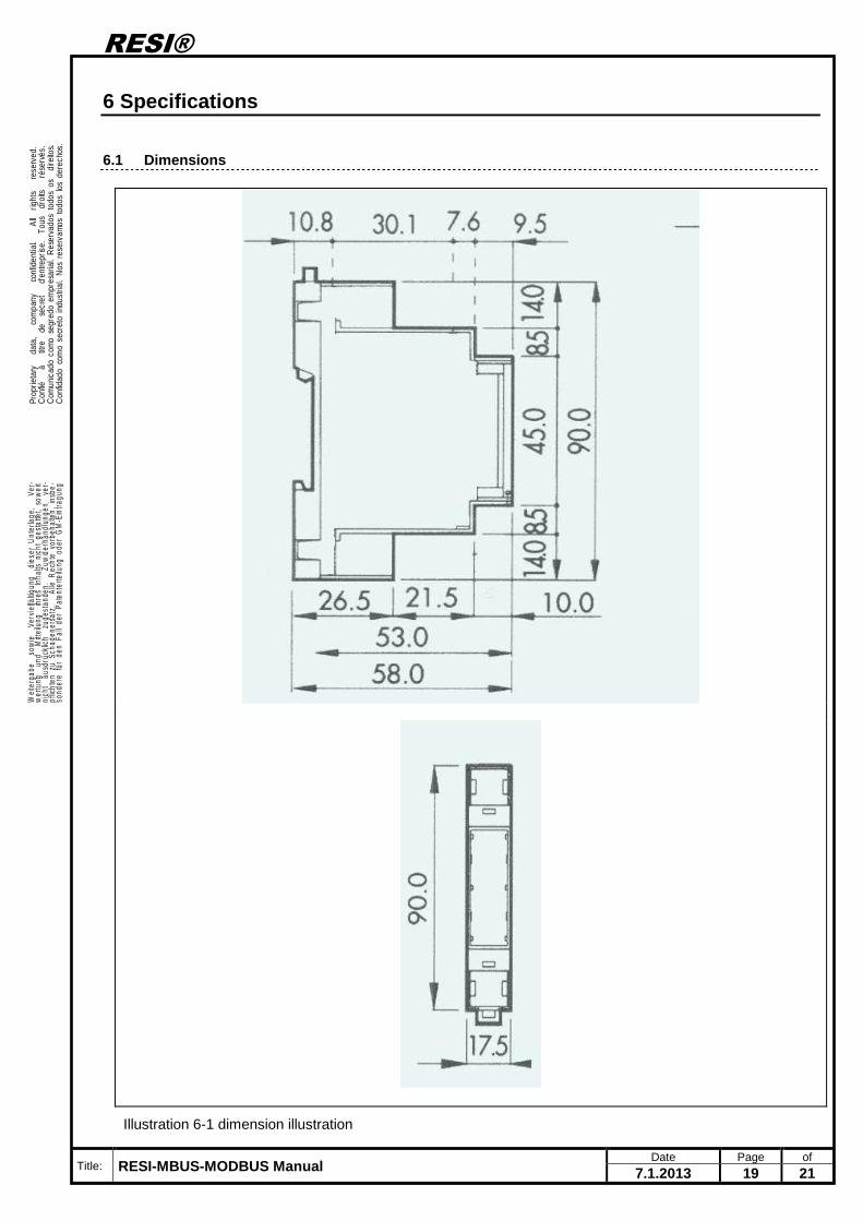
6.1 Dimensions
Illustration 6-1 dimension illustration
RESI®
Title: RESI-MBUS-MODBUS Manual Date Page of
7.1.2013 20 21
. Prop
rieta
ry
dat
a,
com
pany
c
onfid
entia
l.
All
rig
hts
re
serv
ed.
Con
fié
à
titr
e d
e s
ecre
t
d'en
trepr
ise.
To
us
droi
ts
rés
ervé
s.C
omun
icad
o co
mo
segr
edo
empr
esar
ial.
Res
erva
dos
todo
s os
di
reito
s.C
onfid
ado
com
o se
cret
o in
dust
rial.
Nos
res
erva
mos
tod
os lo
s de
rech
os.
.
. Wei
terg
abe
sow
ie
Verv
ielfä
ltigun
g d
iese
r U
nter
lage
,
Ver-
wer
tung
un
d M
ittei
lung
ih
res
Inha
lts n
icht
ges
tatte
t, so
wei
tni
cht
aus
drüc
klich
zu
gest
ande
n.
Zuw
ider
hand
lung
en
ver-
pflic
hten
zu
Scha
dene
rsat
z.
Alle
Rec
hte
vorb
ehal
ten,
ins
be-
sond
ere
für
den
Fall
der
Pate
nter
teilu
ng o
der
GM
-Ein
tragu
ng.
.
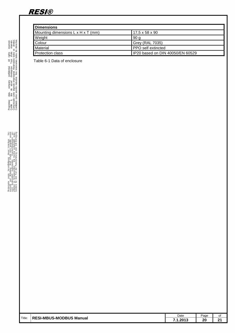
Dimensions Mounting dimensions L x H x T (mm) 17,5 x 58 x 90 Weight 90 g Colour Grey (RAL 7035) Material PPO self extincted Protection class IP20 based on DIN 40050/EN 60529
Table 6-1 Data of enclosure
RESI®
Title: RESI-MBUS-MODBUS Manual Date Page of
7.1.2013 21 21
. Prop
rieta
ry
dat
a,
com
pany
c
onfid
entia
l.
All
rig
hts
re
serv
ed.
Con
fié
à
titr
e d
e s
ecre
t
d'en
trepr
ise.
To
us
droi
ts
rés
ervé
s.C
omun
icad
o co
mo
segr
edo
empr
esar
ial.
Res
erva
dos
todo
s os
di
reito
s.C
onfid
ado
com
o se
cret
o in
dust
rial.
Nos
res
erva
mos
tod
os lo
s de
rech
os.
.
. Wei
terg
abe
sow
ie
Verv
ielfä
ltigun
g d
iese
r U
nter
lage
,
Ver-
wer
tung
un
d M
ittei
lung
ih
res
Inha
lts n
icht
ges
tatte
t, so
wei
tni
cht
aus
drüc
klich
zu
gest
ande
n.
Zuw
ider
hand
lung
en
ver-
pflic
hten
zu
Scha
dene
rsat
z.
Alle
Rec
hte
vorb
ehal
ten,
ins
be-
sond
ere
für
den
Fall
der
Pate
nter
teilu
ng o
der
GM
-Ein
tragu
ng.
.
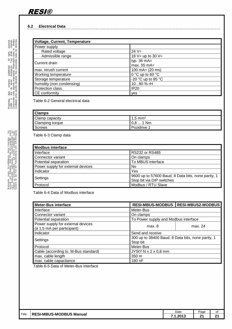
6.2 Electrical Data
Voltage, Current, Temperature Power supply
Rated voltage 24 V= Admissible range 18 V= up to 30 V=
Current drain typ. 36 mA= max. 55 mA=
max. inrush current 100 mA= (20 ms) Working temperature 0 °C up to 60 °C Storage temperature -20 °C up to 85 °C humidity (non condensing) 10...90 % rH Protection class IP20 CE conformity yes
Table 6-2 General electrical data
Clamps Clamp capacity 1,5 mm² Clamping torque 0,8 ... 1 Nm Screws Pozidrive 1
Table 6-3 Clamp data
Modbus interface Interface RS232 or RS485 Connector variant On clamps Potential separation To MBUS interface Power supply for external devices No Indicator Yes
Settings 9600 up to 57600 Baud, 8 Data bits, none parity, 1 Stop bit via DIP switches
Protocol Modbus / RTU Slave
Table 6-4 Data of Modbus interface
Meter-Bus interface RESI-MBUS-MODBUS RESI-MBUS2-MOD BUS Interface Meter-Bus Connector variant On clamps Potential separation To Power supply and Modbus interface Power supply for external devices (á 1,5 mA per participant)
max. 8 max. 24
Indicator Send and receive
Settings 300 up to 38400 Baud, 8 Data bits, none parity, 1 Stop bit
Protocol Meter-Bus Cable (according to. M-Bus standard) JYStY N x 2 x 0,8 mm max. cable length 350 m max. cable capacitance 180 nF
Table 6-5 Data of Meter-Bus interface