Embed Size (px)
Citation preview

RAPIDResearch and Pathwaysto Impact DevelopmentHandbook 1.1a – RAPID Impact Tables
Updated January 2015

Research and Pathways to Impact Development I Page 2
Contents1 Introduction 3
1.1 Scope for Current Document 3
1.2 RAPID – Research and Pathways to Impact Development 3
1.3 Full Scope for RAPID 4
2 Research Area Champions 5
3 RAPID Application Impact Tables 6
3.1 Application Impact Tables 6
3.2 Other RAPID Documents 6
APPENDICES
Appendix 1 The Carbon Capture and Storage Research Centre 35
Research and Pathways to Impact Development I Page 3
1 Introduction1.1 Scope for Current DocumentIn this document previous work to identify areas for research in 2012 is being re-issuedin an updated form to act as an interim working resource for ongoing research prioritydevelopment activities with the UKCCSRC Independent Advisory Panel and otherstakeholders. The material presented may, therefore, be superseded during this processand should not be taken as definitive. Any use is entirely at the discretion of the reader.
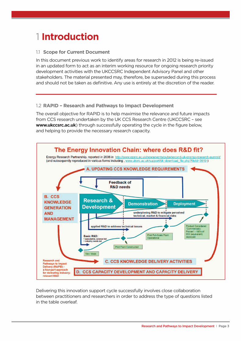
1.2 RAPID – Research and Pathways to Impact DevelopmentThe overall objective for RAPID is to help maximise the relevance and future impactsfrom CCS research undertaken by the UK CCS Research Centre (UKCCSRC – seewww.ukccsrc.ac.uk) through successfully operating the cycle in the figure below,and helping to provide the necessary research capacity.
Delivering this innovation support cycle successfully involves close collaborationbetween practitioners and researchers in order to address the type of questions listedin the table overleaf.

Research and Pathways to Impact Development I Page 4
The Application Impact Tables presented in this document are directed primarily towardsthe questions raised in Part A above. As already noted, further work to identify areas of CCSresearch and evaluate their potential impact is ongoing and these tables are presented asworking documents in support of this process.
A UPDATING CCS KNOWLEDGE REQUIREMENTS1 What knowledge and related capacity will be needed to implement CCS?2 To what extent is necessary knowledge and capacity already available to users?
B CCS KNOWLEDGE GENERATION AND MANAGEMENT3 How can gaps in knowledge be met?
Sliding scale of UKCCSRC involvement. High end of scale to low end of scale- In-house research supported mainly from UKCCSRC funds- In-house research supported mainly from external funds- Joint research with external partners- No research but UKCCSRC role as informed user- UKCCSRC as information clearing house- No UKCCSRC input needed at all
C CCS KNOWLEDGE DELIVERY ACTIVITIES4 How is knowledge made available to users?
Routes depend on knowledge and userIdentify knowledge sources and usersIdentify routes for deliveryLong-term delivery activities
D CAPACTIY DEVELOPMENT AND DELIVERY
5 What UKCCSRC related capacity if required?
6 How is this created, maintained and delivered? e.g. Trained people,experimental/test facilities, methods/standards/regulations, software etc
1.3 Full Scope for RAPID
Research and Pathways to Impact Development I Page 5
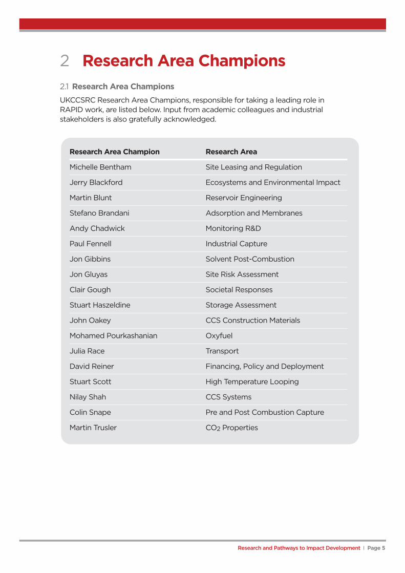
2 Research Area Champions2.1 Research Area ChampionsUKCCSRC Research Area Champions, responsible for taking a leading role inRAPID work, are listed below. Input from academic colleagues and industrialstakeholders is also gratefully acknowledged.
Research Area Champion Research Area
Michelle Bentham Site Leasing and Regulation
Jerry Blackford Ecosystems and Environmental Impact
Martin Blunt Reservoir Engineering
Stefano Brandani Adsorption and Membranes
Andy Chadwick Monitoring R&D
Paul Fennell Industrial Capture
Jon Gibbins Solvent Post-Combustion
Jon Gluyas Site Risk Assessment
Clair Gough Societal Responses
Stuart Haszeldine Storage Assessment
John Oakey CCS Construction Materials
Mohamed Pourkashanian Oxyfuel
Julia Race Transport
David Reiner Financing, Policy and Deployment
Stuart Scott High Temperature Looping
Nilay Shah CCS Systems
Colin Snape Pre and Post Combustion Capture
Martin Trusler CO2 Properties

Research and Pathways to Impact Development I Page 6
3 RAPID Application Impact Tables
CCS Systems 8
Solvent Post-Combustion Capture 9
Post-Combustion (Coal and Gas) Adsorption 10
Pre-Combustion Capture 11
Pre-Combustion Adsorption + Membrane Capture 13
Oxyfuel Combustion Capture 14
High Temperature Looping Cycles 17
Cement 19
High Purity Sources of CO2 21
Iron and Steel 22
Refineries 24
Pipeline Transport 26
Shipping Transport 27
Storage Issues (Aquifer and Depleted Fields) 28
Storage Regulation and Licensing 30
Environmental Impact 31
Public Acceptability and Social Impact 32
Economics and Finance 33
CO2 and Related Substance Properties 34
Application Impact Tables havebeen prepared for a number ofareas, which largely cover therange of applications shown in theFigure opposite, taken from theUKCCSRC proposal. These areshown on the following pages.
3.2 Other Rapid DocumentsResearch Area Champions, oftenwith input from other stakeholders,have prepared summaries ofresearch needed in different areasand possible pathways to deliveryfor missing impacts. A number ofResearch Area Champions havealso assessed overall researchneeds more widely. These canbe found in RAPID Handbook1.1b – Research Area Summariesand Needs.
A comprehensive list of CCS projects in the UK is available from the UKCCSRC websitehttps://ukccsrc.ac.uk/resources/ccs-projects-directory (please note that the directory isconstantly updated and input from members is welcome).
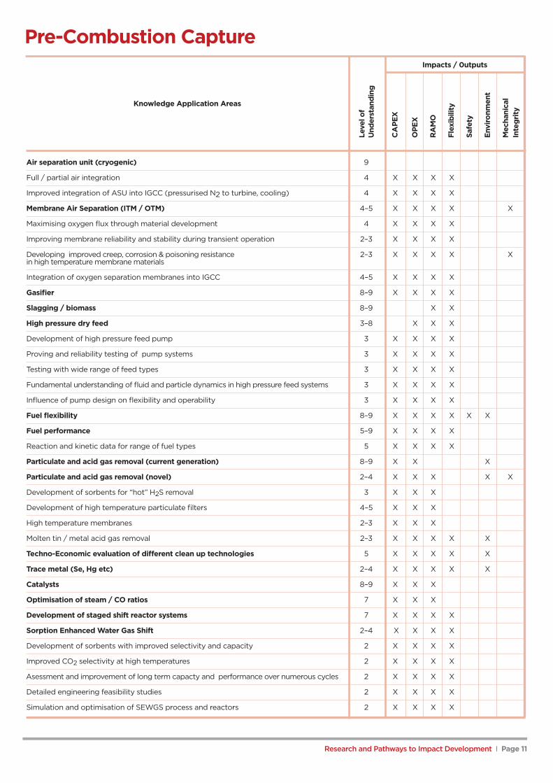
3.1 Application Impact TablesThe RAPID Application Impact Tables (AITs) are intended to summarise in detail theknowledge required to implement particular CCS applications.
The AITs presented in this report have been reviewed and updated by the UKCCSRC ResearchArea Champions and the format for each table is relevant to that particular topic area.
Current AIT headings are:
Knowledge Application Areas Individual knowledge inputs required to effectthis application
Level of Understanding An estimate of how fully this knowledge is available toCCS practitioners, shown as a numerical value where:1, 2,3 = Novel ; 4, 5, 6 = Intermediate ; 7, 8, 9 = Mature
Impacts / outputs Notes of the fields (e.g. Capital Cost, Safety, Environment) inwhich application of the knowledge may have a future impact.

Research and Pathways to Impact Development I Page 7
TAB
LE
S
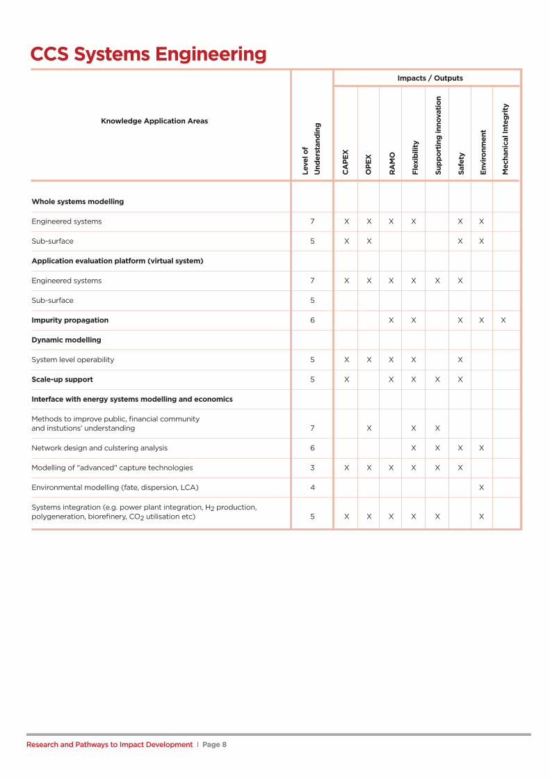
CCS Systems EngineeringImpacts / Outputs
Whole systems modelling
Engineered systems 7 X X X X X X
Sub-surface 5 X X X X
Application evaluation platform (virtual system)
Engineered systems 7 X X X X X X
Sub-surface 5
Impurity propagation 6 X X X X X
Dynamic modelling
System level operability 5 X X X X X
Scale-up support 5 X X X X X
Interface with energy systems modelling and economics
Methods to improve public, financial communityand instutions' understanding 7 X X X
Network design and culstering analysis 6 X X X X
Modelling of "advanced" capture technologies 3 X X X X X X
Environmental modelling (fate, dispersion, LCA) 4 X
Systems integration (e.g. power plant integration, H2 production,polygeneration, biorefinery, CO2 utilisation etc) 5 X X X X X X
Leve
lof
Und
erst
andi
ng
CA
PEx
OPE
x
RA
MO
Flex
ibili
ty
Supp
ortin
gin
nova
tion
Safe
ty
Envi
ronm
ent
Mec
hani
calI
nteg
rity
Research and Pathways to Impact Development I Page 8
Knowledge Application Areas
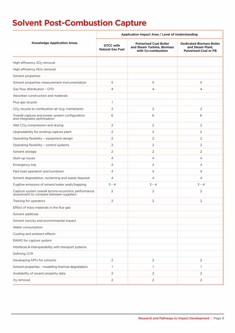
Solvent Post-Combustion CaptureApplication Impact Area / Level of Understanding
Pulverised Coal Boiler Dedicated Biomass Boilerand Steam Turbine, Biomass and Steam Plant,
with Co-combustion Pulverised Coal or FB
High efficiency SO2 removal
High efficiency NOx removal
Solvent properties
Solvent properties measurement instrumentation 5 5 5
Gas flow distribution – CFD 4 4 4
Absorber construction and materials
Flue gas recycle 1
CO2 recycle to combustion air (e.g. membrane) 2 2 2
Overall capture and power system configuration 6 6 6and integrated optimisation
Wet CO2 compression and drying 2 2 2
Upgradability for existing capture plant 2 2 2
Operating flexibility – equipment design 2 2 2
Operating flexibility – control systems 2 2 2
Solvent storage 2 2 2
Start-up issues 4 4 4
Emergency trip 4 4 4
Part-load operation and turndown 4 4 4
Solvent degradation, reclaiming and waste disposal 4 4 4
Fugitive emissions of solvent/water wash/trapping 3 – 4 3 – 4 3 – 4
Capture system overall techno-economic performance 2 2 2assessment to compare between suppliers
Training for operators 2 2 2
Effect of trace materials in the flue gas
Solvent additives
Solvent toxicity and environmental impact
Water consumption
Cooling and ambient effects
RAMO for capture system
Interfaces & interoperability with transport systems
Defining CCR
Developing KPI's for solvents 2 2 2
Solvent properties – modelling thermal degradation 1 1 1
Availability of sovent property data 2 2 2
O2 removal 2 2 2
Research and Pathways to Impact Development I Page 9
Knowledge Application AreasGTCC with
Natural Gas Fuel

Research and Pathways to Impact Development I Page 10
Post-Combustion (Coal and Gas) AdsorptionImpacts / Outputs
Materials
Development of materials to meet working capacity targets 4–6 X X X
Optimisaton of physical properties 4–6 X X
Optimisation of surface chemistry 3–5 X X X
Development of materials optimised for gas combustion capture 2 X X X
Optimisation of CO2 selectivity 4–6 X X X
Selectivity and tolerance vs water 2–6 X X X
Improving oxidative stability 3–6 X X X
> Physisorbents 4–6 X X X
> Chemisorbents (for example immobilised amines) 3 X X X
Optimising cyclic stability in range of regeneration gases (CO2 steam TSA) 3 X X
Kinetic evaluation and optimisation 2–6 X X
> Physisorbents 4–6 X X X
> Chemisorbents 2–3 X X X
Fundamental understanding of degradation mechanisms 2 X
Evaluation of materials performance in simulated flue gases 3 X X X X
Predictive models for materials development 2–5 X
Determination of fate of trace elements in adsorbents 2 X X X
Process
Development of regeneration cycles TSA 4–6 X X X X
Development of regeneration cycles PSA / VSA 4–6 X X X X
Cycles for capture form gas combustion 3–5 X X X X
Novel, efficient regeneration methods 1–2 X X X X X X
Strategies for acid gas (SOx, NOx) removal & control 2 X X X X X
Conceptual designs of adsorption capture plants 4 X X X X
Fixed bed processes 6 X X X X
Circulating fluidised beds 3–5 X X X X
Simulated moving beds 3–5
Plant integration 3–4 X X X X
Development of process simulation models 4–6 X X X X
Interaction with transport & storage (CO2 purity etc) 2 X X X X
Requirement for gas pre-treatment prior to contactor 2 X X X X
Module design (mem) 4–6 X X X X
Multistage membrane processes 4–6 X X X X
Measurement and control of fouling (requires slip stream) 2–3 X X X X
Scale-up
Scale-up of materials synthesis 2–6 X X
Small pilot scale testing (ie 10 kw slip stream)
Leve
lof
Und
erst
andi
ng
CA
PEx
OPE
x
RA
MO
Flex
ibili
ty
Safe
ty
Envi
ronm
ent
Mec
hani
cal
Inte
grity
Knowledge Application Areas
Research and Pathways to Impact Development I Page 11
Pre-Combustion CaptureImpacts / 0utputs
Air separation unit (cryogenic) 9
Full / partial air integration 4 X X X X
Improved integration of ASU into IGCC (pressurised N2 to turbine, cooling) 4 X X X X
Membrane Air Separation (ITM / OTM) 4–5 X X X X X
Maximising oxygen flux through material development 4 X X X X
Improving membrane reliability and stability during transient operation 2–3 X X X X
Developing improved creep, corrosion & poisoning resistance 2–3 X X X X Xin high temperature membrane materials
Integration of oxygen separation membranes into IGCC 4–5 X X X X
Gasifier 8–9 X X X X
Slagging / biomass 8–9 X X
High pressure dry feed 3–8 X X X
Development of high pressure feed pump 3 X X X X
Proving and reliability testing of pump systems 3 X X X X
Testing with wide range of feed types 3 X X X X
Fundamental understanding of fluid and particle dynamics in high pressure feed systems 3 X X X X
Influence of pump design on flexibility and operability 3 X X X X
Fuel flexibility 8–9 X X X X X X
Fuel performance 5–9 X X X X
Reaction and kinetic data for range of fuel types 5 X X X X
Particulate and acid gas removal (current generation) 8–9 X X X
Particulate and acid gas removal (novel) 2–4 X X X X X
Development of sorbents for “hot” H2S removal 3 X X X
Development of high temperature particulate filters 4–5 X X X
High temperature membranes 2–3 X X X
Molten tin / metal acid gas removal 2–3 X X X X X
Techno-Economic evaluation of different clean up technologies 5 X X X X X
Trace metal (Se, Hg etc) 2–4 X X X X X
Catalysts 8–9 X X X
Optimisation of steam / CO ratios 7 X X X
Development of staged shift reactor systems 7 X X X X
Sorption Enhanced Water Gas Shift 2–4 X X X X
Development of sorbents with improved selectivity and capacity 2 X X X X
Improved CO2 selectivity at high temperatures 2 X X X X
Asessment and improvement of long term capacty and performance over numerous cycles 2 X X X X
Detailed engineering feasibility studies 2 X X X X
Simulation and optimisation of SEWGS process and reactors 2 X X X X
Leve
lof
Und
erst
andi
ng
CA
PEx
OPE
x
RA
MO
Flex
ibili
ty
Safe
ty
Envi
ronm
ent
Mec
hani
cal
Inte
grity
Knowledge Application Areas
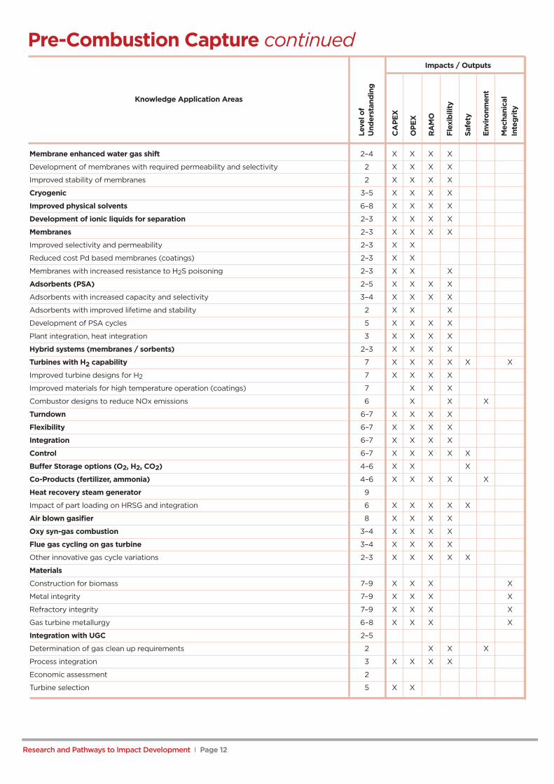
Pre-Combustion Capture continuedImpacts / Outputs
Membrane enhanced water gas shift 2–4 X X X X
Development of membranes with required permeability and selectivity 2 X X X X
Improved stability of membranes 2 X X X X
Cryogenic 3–5 X X X X
Improved physical solvents 6–8 X X X X
Development of ionic liquids for separation 2–3 X X X X
Membranes 2–3 X X X X
Improved selectivity and permeability 2–3 X X
Reduced cost Pd based membranes (coatings) 2–3 X X
Membranes with increased resistance to H2S poisoning 2–3 X X X
Adsorbents (PSA) 2–5 X X X X
Adsorbents with increased capacity and selectivity 3–4 X X X X
Adsorbents with improved lifetime and stability 2 X X X
Development of PSA cycles 5 X X X X
Plant integration, heat integration 3 X X X X
Hybrid systems (membranes / sorbents) 2–3 X X X X
Turbines with H2 capability 7 X X X X X X
Improved turbine designs for H2 7 X X X X
Improved materials for high temperature operation (coatings) 7 X X X
Combustor designs to reduce NOx emissions 6 X X X
Turndown 6–7 X X X X
Flexibility 6–7 X X X X
Integration 6–7 X X X X
Control 6–7 X X X X X
Buffer Storage options (O2, H2, CO2) 4–6 X X X
Co-Products (fertilizer, ammonia) 4–6 X X X X X
Heat recovery steam generator 9
Impact of part loading on HRSG and integration 6 X X X X X
Air blown gasifier 8 X X X X
Oxy syn-gas combustion 3–4 X X X X
Flue gas cycling on gas turbine 3–4 X X X X
Other innovative gas cycle variations 2–3 X X X X X
Materials
Construction for biomass 7–9 X X X X
Metal integrity 7–9 X X X X
Refractory integrity 7–9 X X X X
Gas turbine metallurgy 6–8 X X X X
Integration with UGC 2–5
Determination of gas clean up requirements 2 X X X
Process integration 3 X X X X
Economic assessment 2
Turbine selection 5 X X
Leve
lof
Und
erst
andi
ng
CA
PEx
OPE
x
RA
MO
Flex
ibili
ty
Safe
ty
Envi
ronm
ent
Mec
hani
cal
Inte
grity
Research and Pathways to Impact Development I Page 12
Knowledge Application Areas

Research and Pathways to Impact Development I Page 13
Pre-Combustion Adsorption + Membrane CaptureImpacts / Outputs
Materials
Low temperature adsorbents and membranes
> Development of high capacity physisorbents
> Development of materials to meet working capacity targets 4–6 X X X
> Optimisaton of physical properties 4–6 X X
> Optimisation of CO2 selectivity 4–6 X X X
> Kinetic evaluation and optimisation 5 X X
> Determination of fate of trace elements in adsorbents 2 X X X
> Development of polymeric membranes 3 X X
> Development of mixed matrix membranes 2 X X
Sorption enhanced water gas shift (eg hydrotalcites and high temp materials) 2–4 X X X X
> Development of sorbents with improved selectivity and capacity 5–6 X X X X
> Improved CO2 selectivity at high temperatures 4 X X X X
> Asessment and improvement of long term capacty and 4 X X X Xperformance over numerous cycles
> Detailed engineering feasibility studies 4 X X X X
> Simulation and optimisation of SEWGS process and reactors 4 X X X X
Membrane enhanced water gas shift 2–4 X X X X
> Development of membranes with required permeability & selectivity 2 X X X X
> Improved stability of membranes 2 X X X X
Membranes capture 2–3 X X X X
> Improved selectivity and permeability 2–3 X X
> Reduced cost Pd based membranes (coatings) 2–3 X X
> Membranes with increased resistance to H2S poisoning 2–3 X X X
Process
Development of regeneration cycles PSA / VSA 4–6 X X X X
Strategies for acid gas (H2S) removal and control 2 X X X X X
Adsorption capture plant conceptual designs 4 X X X X
Fixed bed processes 6 X X X X
Circulating fluidised beds 3–5 X X X X
Simulated moving beds 3–5
Plant integration 3–4 X X X X
Development of process simulation models 4–6 X X X X
Requirement for gas pre-treatment prior to contactor 2 X X X X
Module design (mem) 4–6 X X X X
Multistage membrane processes 4–6 X X X X
Leve
lof
Und
erst
andi
ng
CA
PEx
OPE
x
RA
MO
Flex
ibili
ty
Safe
ty
Envi
ronm
ent
Mec
hani
cal
Inte
grity
Knowledge Application Areas

Research and Pathways to Impact Development I Page 14
Oxy-Fuel Combustion CaptureImpacts / Outputs
Oxygen production
Cryogenic air separation 8–9 X 1–2%
> Full / partial air integration 4 X X X X
> Improved integration of ASU into oxyfuel power plant 3–4 X X X X
Membrane air separation (ITM / OTM)
Membrane air separation (ITM / OTM) incl. HT ceramic 3–4 X X X X X X 4–5%
Maximising oxygen flux through materials development 4 X X X X
Improving membrane reliability and stability during transient operation 2 – 3 X X X X
Developing next generation membrane air separation 2 X X X X X
Developing improved creep, corrosion and poisoning 2 X X X X Xresistance in high temperature membrane materials
Scale up, process intensification and process integration 4–5 X X X X
Oxygen production by chemical air separation 3 X X X X X up to40%
O2 production
Integration of oxygen separation membranes into oxy-fuel boiler 3–4 X X X X X 5–6%
Oxy-solid fuel (including biomass) boiler
Ash fouling/slagging 5–8 X X X X
> Coal 8 X X X X
> Biomass 5 X X X X
Low and high temperature corrosion 6 X X X X
Air leakage 5 X X X X
Emission and pollutant formation 5 X X X X
> SO2/SO3 4 X X X X
> Hg behavior 3 X X X X X
> Fuel NOx formation 3 X X X
Numerical modelling 7 X X X X
> Radiative heat transfer 4 X X X X
> Char oxidation and burnout 4 X X X X
Feed System 3–8 X X X
> Testing with wide range of feed types 4 X X X X
> Biomass safety 5 X X X X
> Biomass particle size and shape 3 X X X X
Fuel flexibility (including co-firing) 6–8 X X X X X X
Fuel performance 5–9 X X X X
> Reaction & kinetic data for range of fuel types & conditions 3 X X X X
Oxy-gas turbine (including alternative fuels e.g. Syngas, H2, biofuels)
Turbines with O2 capability 2–4 X X X X
> Improved turbine designs for O2 6–8 X X X X
> Improved materials for high temperature operation (coatings) 2–5 X X X X X
> Combustor designs to reduce NOx emissions 3 X X X X
Fuel flexibility 6–8 X X X X X X
Fuel performance 4–8 X X X X
> Reaction and kinetic data for range of fuel types 3 X X X X
Combustion CFD and heat transfer 2 X X X X
Cooling systems 4 X X X X X
Leve
lof
Und
erst
andi
ng
CA
PEx
OP
Ex
RA
MO
Flex
ibili
ty
Safe
ty
Envi
ronm
ent
Mec
hani
cal
Inte
grity
Effici
ency
Gai
n(%
)
Knowledge Application Areas

Research and Pathways to Impact Development I Page 15
Oxy-Fuel Combustion Capture continuedImpacts / Outputs
Flue gas recycling and O2 mixing
Safety testing of technologies and materials 4 X X X X X X
Positioning of O2 and RFG mixing points 3 X X X
Process control 5 X X X
Gas clean up
Particulate and acid gas removal (current generation) 8–9 X X X
Particulate and acid gas removal (novel) 2–4 X X X X X
> Development of sorbents for “hot” H2S removal 3 X X X
> Development of high temperature particulate filters 4–5 X X X
> High temperature membranes 2–3 X X X
DeNOx plants (SCR and SNCR) 6 X X X X X
N2/O2 gas separation technology 3–5 X X X X 4–6%
Techno-economic evaluation of different clean up technologies 5 X X X X X
Trace metal (Se, Hg etc.) 2–4 X X X X X
CO2 compression and purifications
Removal of SOx and NOx at compression stage 2 X X X X X X X
Improved efficiency 5 X X
Materials 7 X X X X X
Process intensification
Chemical looping combustion 5 X X X X X
> Development and sourcing of oxygen carriers 5 X X X X X
> Fuel conversion efficiency 5 X X X X X
> Scale up and integration 4 X X X X X X
> Reactor design, optimisation and materials selection 5 X X X X X X
Oxygen transport membrane reactors 3 X X X X X
> Materials development 3 X X X X X
> Reactor development 3 X X X X X
> Integration 2 X X X X
Virtual oxy-fuel system simulation
Basic data and models
> Process simulation 7 X X X X
> CFD 4 X X X X
> Molecular modelling 2–3 X X X X
Device scale simulation tools/models 4 X X X X
> Scale bridging 4 X X X X
Techno-economic models 6 X X X X
Reduced order model development 3–4 X X X X
Process synthesis & design tools/models 4–6 X X X X
Optimization algorithm 5 X X X X
Plant operations and control tools & models 4–6 X X X X
Integration framework 4–6 X X X X
Leve
lof
Und
erst
andi
ng
CA
PEx
OPE
x
RA
MO
Flex
ibili
ty
Safe
ty
Envi
ronm
ent
Mec
hani
cal
Inte
grity
Effici
ency
Gai
n(%
)Knowledge Application Areas

Oxy-Fuel Combustion Capture continuedImpacts / Outputs
Operability
Turndown 6–7 X X X X
Flexibility
> Oxy-fuel boiler 5–7 X X X X
> Oxy-fuel gas turbine 5–6 X X X X
Integration X
> Oxy-fuel gas turbine 4 X X X X
> Oxy-fuel boiler 6 X X X X
Cooling Gas 4–6 X X X X
Control 4–7 X X X X X
Buffer storage options (O2, H2, CO2) 4–6 X X X
Co-products (fertilizer, ammonia) 4–6 X X X X X
Innovative cycles
Allam cycle 4 X X X X 15%
Oxy syn-gas combustion 3–4 X X X X
HAT and oxy-HAT cycle 5–3 X X X X 10%
Flue gas cycling on gas turbine 3–5 X X X X
Other innovative gas cycle variations 2–4 X X X X
Materials
Construction for HT combustion chamber 5 X X X X
Construction for HT turbine 5 X X X X X
Construction for biomass 5 X X X X X
Metal integrity 7–8 X X X X
Refractory integrity 7–8 X X X X
Gas turbine metallurgy 6–8 X X X X
Underground coal gasification + oxyfuel CCS
Integration with UGC 2–5
Overground coal gasification + oxyfuel CCS
Determination of gas clean up requirements 2 XX XX XX
Process integration 3 X X X X
Economic assessment 2
Turbine selection 5 X X
Leve
lof
Und
erst
andi
ng
CA
PEx
OPE
x
RA
MO
Flex
ibili
ty
Safe
ty
Envi
ronm
ent
Mec
hani
cal
Inte
grity
Effici
ency
Gai
n(%
)
Research and Pathways to Impact Development I Page 16
Knowledge Application Areas

Research and Pathways to Impact Development I Page 17
High Temperature Looping CyclesImpacts / 0utputs
Post combustion carbonate looping
Flow sheet and process optimisation
> Flow sheet optimisation 5 X X X X X
> Linking flowsheet at system level to macro-economic processes 4 X X X X X
> Flexibility – is load following possible or economic? 3 X X X
CO2 sorbent materials
> Sorbent selection (natural materials) 7 X X
> Modification of natural materials for sorbents 3 X X X
> Sorbent regeneration 2 X
> Novel materials (cost effective artificial sorbents) 3 X
> Degradation mechanisms 3 X X
> Pollutant emissions & interaction with minor components 3 X X X
> Pore scale/particle scale modelling & understanding 4 X X
> Kinetics and evolution of material with cycling 3 X
> Interaction with ash 3 X X X X
Reactor systems and reactor modelling
> Dual fluidised bed design 8 X X
> Modelling fluidised beds 8 X X X
> Optimisation of reactor conditions for maximum capture 7 X
> Control of dual fluidised bed systems 8 X
> Final CO2 purity and fate of minor components 6 X X X
Carbonate looping applied to pre-combustion of natural gas
Performance of sorbents in reducing/ reforming atmospheres 4 X
Interactions with reforming catalysts or sorbent additives 3 X
Metal oxide chemical looping
Flow sheet and process optimisation
> Flowsheet optimisation 3 X X X X X
> Linking flowsheet at system level to macro-economic processes 3 X X X X X X
> Flexibility – is load following possible or economic? 3 X X X
> Application to industrial systems 3 X X X X X X
Oxygen carriers
> Use of natural materials as oxygen carriers 5 X X X
> Modification of natural materials as oxygen carriers 3 X X X X
> Novel materials for oxygen carriers 2 X X X
> Cost effect production of materials 6 X
> Degradation mechanisms 3 X X
> Pollutant emissions & interaction with minor components 3 X X X
> Pore scale/particle scale modelling & understanding 4 X X
> Kinetics and evolution of material with cycling. 2 X
Leve
lof
Und
erst
andi
ng
CA
PEx
OPE
x
Flex
ibili
ty
Rel
iabi
lity
Safe
ty
Envi
ronm
ent
Emis
sion
s
Knowledge Application Areas

Research and Pathways to Impact Development I Page 18
High Temperature Looping Cycles continuedImpacts / 0utputs
Metal oxide chemical looping
Reactor systems and reactor modelling
> Dual fluidised bed design 8 X X
> Modelling fluidised beds 8 X X X
Solid fuels
> Interaction of ash with oxygen carriers 5 X X X X
> Fate of sulphur and its interaction with the carrier 3 X X
> Fate of nitrogen 2 X X X X
> Fate of trace elements 2 x X X X
> Dealing with low reactivity chars–carbon separation 3 X X X
Other issues
> Application to gas fired stations 4 X X X
> Operation at elevated pressure 3 X X X X
Looping for oxygen production (temperature swing redox cycles)
Flowsheet
> Heat integration and energy recovery 2 X X
> Integration with oxyfuel boiler 2 X X
Materials for oxygen release
> Thermodynamics of metal oxides 7 X X X X
> Thermodynamic properties of novel oxide & kintics of release 2 X
> Formulation of materials 5 X
Reactor systems
> Reactor design and optmisation 3 X X X X
Leve
lof
Und
erst
andi
ng
CA
PEx
OPE
x
Flex
ibili
ty
Rel
iabi
lity
Safe
ty
Envi
ronm
ent
Emis
sion
sKnowledge Application Areas

Research and Pathways to Impact Development I Page 19
CementImpacts / Outputs
Post 'process' captureGeneral
> Flowsheeting and design 5 X X
> Modelling of heat integration options 5 X X
> Possibilities for flexible operation 2 X X X X
> Retrofittability 4 X
> Control and operability 5 X X X X X
Gas clean up
> Particulate and acid gas removal (current generation) 8–9 X X X
> Particulate and acid gas removal (novel) 2–4 X X X X X
> High temperature membranes 2–3 X X X
> Molten tin/metal acid gas removal 2–3 X X X X
> Trace element (Se, etc.) 2–4 X X X X
CO2 separation
> Determining optimal CO2 separation technology 5 X X
> Impact of flue gas composition and trace elements 2 X X X
> Physical solvents 2 X X
> Cryogenic 4–5 X X X X
> Membranes 3–5 X X X X
Adsorbents (PSA) 2–3 X X X X
> Hybrid systems (membranes/sorbents) 2–5 X X X X
> Ab/adsorption column sizing 4 X X
Carbonate looping 5
General
> Flowsheeting and design 5 X X
> Integration with power plants with Ca-looping 5 X X X X
> Modelling of heat integration options 5 X X
> Possibilities for flexible operation 2 X X X X
> Retrofittability 4 X
> Control and operability 5 X X X X X
Gas clean up
> Particulate and acid gas removal (current generation) 8–9 X X X
> Particulate and acid gas removal (novel) 2–4 X X X X X
> High temperature membranes 2–3 X X X
> Molten tin/metal acid gas removal 2–3 X X X X
> Trace element (Se, etc.) 2–4 X X X X
Cement kiln operation
> Recycle of spent sorbent to the kiln – impact on cement quality 2–3 X X
Carbonator/calciner design and operation
> Sorbent selection (natural materials) 5 X X X
> Modification of natural materials for sorbents 3 X X X
> Sorbent regeneration 3 X
> Novel materials (cost effective artificial sorbents) 3 X X
> Degradation mechanisms 3 X X
> Sorbent attrition 5 X X
> Pore scale/particle scale modelling and understanding 4 X
> Kinetics and evolution of material with cycling 4 X
> Interaction with ash 4 X X
> Impact of flue gas composition and trace elements 3 X
> Modelling, design and operation of fluidised beds 5 X X X X
> Reactor sizing 4 X X
Leve
lof
Und
erst
andi
ng
CA
PEx
OPE
x
RA
MO
Flex
ibili
ty
Safe
ty
Envi
ronm
ent
Mec
hani
cal
Inte
grity
Knowledge Application Areas

Research and Pathways to Impact Development I Page 20
Cement continuedImpacts / Outputs
Oxyfuel
General
> Flowsheeting and design 5 X X X
> Modelling of heat integration options 5 X X
> Possibilities for flexible operation 3 X X X X
> Retrofittability 4 X X
> Control and operability 5 X X X X X
Cement process units operation
> Impact of CO2 concentration on cement quality 4 X X X
> Modelling of temperature profiles in the kiln 4 X X X X
> Control of air leakage into the kiln 3 X X X X X
Gas Clean up
> Particulate and acid gas removal (current generation) 8–9 X X X
> Particulate and acid gas removal (novel) 2–4 X X X X X
> High temperature membranes 2–3 X X X
> Molten tin/metal acid gas removal 2–3 X X X X
> Trace metal (Se, etc) 2–4 X X X X
Leve
lof
Und
erst
andi
ng
CA
PEx
OPE
x
RA
MO
Flex
ibili
ty
Safe
ty
Envi
ronm
ent
Mec
hani
cal
Inte
grity
Knowledge Application Areas

Research and Pathways to Impact Development I Page 21
High Purity Sources of CO2Impacts / Outputs
General
Flowsheeting and design 4–9 X X
Modelling of heat integration options 4–9 X X
Possibilities for flexible operation 3 X X X X
Retrofittability 4 X
Control and operability 4–9 X X X X X
CO2 separation
Determining optimal CO2 separation technology 3–9 X X
Impact of flue gas composition and trace elements 2–9 X X X
Physical solvents 2–9 X X
Cryogenic 6–8 X X X X
Membranes 3–5 X X X X
Adsorbents (PSA) 2–3 X X X X
Hybrid systems (membranes/sorbents) 2–5 X X X X
Ab/adsorption column sizing 3–9 X X
Leve
lof
Und
erst
andi
ng
CA
PEx
OPE
x
RA
MO
Flex
ibili
ty
Safe
ty
Envi
ronm
ent
Mec
hani
cal
Inte
grity
Knowledge Application Areas

Research and Pathways to Impact Development I Page 22
Iron and SteelImpacts / Outputs
Top gas recycling blast furnace
General
> Flowsheeting and design 5 X X
> Modelling of heat integration options 4 X X
> Possibilities for flexible operation 1 X X X X
> Retrofittability 4 X
> Control and operability 4 X X X X X
Blast furnace operation
> Temperature profiles within the blast furnace and impact 5 X Xof oxygen injection as well as gas recycle
> Effect of gas recycle on the reduction reaction and metal quality 5 X
Water-gas shift
> Catalysts 8–9 X X X
> Sorption enhanced water gas shift 2–4 X X X X
> Membrane enhanced water gas shift 2–4 X X X X
Gas clean up
> Particulate and acid gas removal (current generation) 8–9 X X X
> Particulate and acid gas removal (novel) 2–4 X X X X X
> High temperature membranes 2–3 X X X
> Molten tin / metal acid gas removal 2–3 X X X X
> Trace metal (Se, etc) 2–4 X X X X
CO2 separation
> Determining optimal CO2 separation technology 3 X X
> Impact of flue gas composition and trace elements 2 X X X
> High temperature sorbents 2 X X X X
> Physical solvents 6–8 X X
> Cryogenic 3–5 X X X X
> Membranes 2–3 X X X X
> Adsorbents (PSA) 2–5 X X X X
> Hybrid systems (membranes / sorbents) 2–3 X X X X
> Ab/adsorption column sizing 5 X X
Pre-combustion capture from direct reduced iron process
General
> Flowsheeting and design 5 X X
> Modelling of heat integration options 5 X X
> Possibilities for flexible operation 1 X X X X
> Retrofittability 4 X
> Control and operability 5 X X X X X
Reducing gas
> Natural gas reforming 9 X X X X
> Coal gasification 9 X X X X
Gas clean up
> Particulate and acid gas removal (current generation) 8–9 X X X
> Particulate and acid gas removal (novel) 2–4 X X X X X
> High temperature membranes 2–3 X X X
> Molten tin/metal acid gas removal 2–3 X X X X
> Trace metal (Se, etc) 2–4 X X X X
Leve
lof
Und
erst
andi
ng
CA
PEx
OPE
x
RA
MO
Flex
ibili
ty
Safe
ty
Envi
ronm
ent
Mec
hani
cal
Inte
grity
Knowledge Application Areas

Iron and Steel continuedImpacts / Outputs
Pre-combustion capture from direct reduced iron process
DRI reactor operation
> Temperature profiles within the DRI reactor 8 X X X X
> Effect of gas recycle on the reduction reaction and metal quality 4 X X
Water-gas shift
> Catalysts 8–9 X X X
> Sorption enhanced water gas shift 2–4 X X X X
> Membrane enhanced water gas shift 2–4 X X X X
CO2 separation
> Determining optimal CO2 separation technology 3 X X
> Impact of flue gas composition and trace elements 2 X X X
> High temperature sorbents 2 X X X X
> Physical solvents 6–8 X X
> Cryogenic 3–5 X X X X
> Membranes 2–3 X X X X
> Adsorbents (PSA) 2–5 X X X X
> Hybrid systems (membranes/sorbents) 2–3 X X X X
> Ab/adsorption column sizing 5 X X
Oxyfuel (HIsarna process)
General
> Flowsheeting and design 5 X X
> Modelling of heat integration options 5 X X
> Possibilities for flexible operation 1 X X X X
> Retrofittability 4 X
> Control and operability 5 X X X X X
Smelt reactor operation
> Temperature profiles 5 X X X X
Gas clean up
> Particulate and acid gas removal (current generation) 8–9 X X X
> Particulate and acid gas removal (novel) 2–4 X X X X X
> High temperature membranes 2–3 X X X
> Molten tin / metal acid gas removal 2–3 X X X X
> Trace element (Se, etc) 2–4 X X X X
Leve
lof
Und
erst
andi
ng
CA
PEx
OPE
x
RA
MO
Flex
ibili
ty
Safe
ty
Envi
ronm
ent
Mec
hani
cal
Inte
grity
Research and Pathways to Impact Development I Page 23
Knowledge Application Areas

Research and Pathways to Impact Development I Page 24
RefineriesImpacts / Outputs
Hydrogen production
General
> Flowsheeting and design 8 X X
> Modelling of heat integration options 8 X X
> Possibilities for flexible operation 1 X X X X
> Control and operability 8 X X X X X
Gas clean up
> Particulate and acid gas removal (current generation) 8–9 X X X
> Particulate & acid gas removal (novel) 2–4 X X X X X
> High temperature membranes 2–3 X X X
> Molten tin / metal acid gas removal 2–3 X X X X
> Trace metal (Se, etc) 2–4 X X X X
CO2 separation
> Determining optimal CO2 separation technology 3 X X
> Impact of flue gas composition and trace elements 2 X X X
> High temperature sorbents 2 X X X X
> Physical solvents 6–8 X X
> Cryogenic 3–5 X X X X
> Membranes 2–3 X X X X
> Adsorbents (PSA) 2–5 X X X X
> Hybrid systems (membranes / sorbents) 2–3 X X X X
> Ab/adsorption column sizing 3–9 X X
Chemical looping reforming for hydrogen production
General
> Flowsheeting and design 3 X X
> Modelling of heat integration options 3 X X
> Possibilities for flexible operation 1 X X X X
> Control and operability 3 X X X X X
Chemical looping reformer
> Oxygen carrier selection (natural materials) 3 X X X
> Modification of natural materials for oxygen carriers 2 X X X
> Sorbent regeneration 2 X X X
> Novel materials (cost effective artificial oxygen carrier) 6–8 X X X
> Degradation mechanisms 3–5 X X
> Oxygen carrier attrition 2–3 X X
> Pore scale/particle scale modelling and understanding 2–5 X
> Kinetics and evolution of material with cycling 2–3 X X
> Impact of flue gas composition and trace elements 4 X X
> Modelling, design and operation of fluidised beds 5 X X X X
> Reactor sizing 5 X X
FCC: Post-combustion capture from FCC unit
General
> Flowsheeting and design 4 X X
> Modelling of heat integration options 4 X X
> Possibilities for flexible operation 1 X X X X
> Retrofittability 4 X
> Control and operability 4 X X X X X
Leve
lof
Und
erst
andi
ng
CA
PEx
OPE
x
RA
MO
Flex
ibili
ty
Safe
ty
Envi
ronm
ent
Mec
hani
cal
Inte
grity
Knowledge Application Areas
Research and Pathways to Impact Development I Page 25
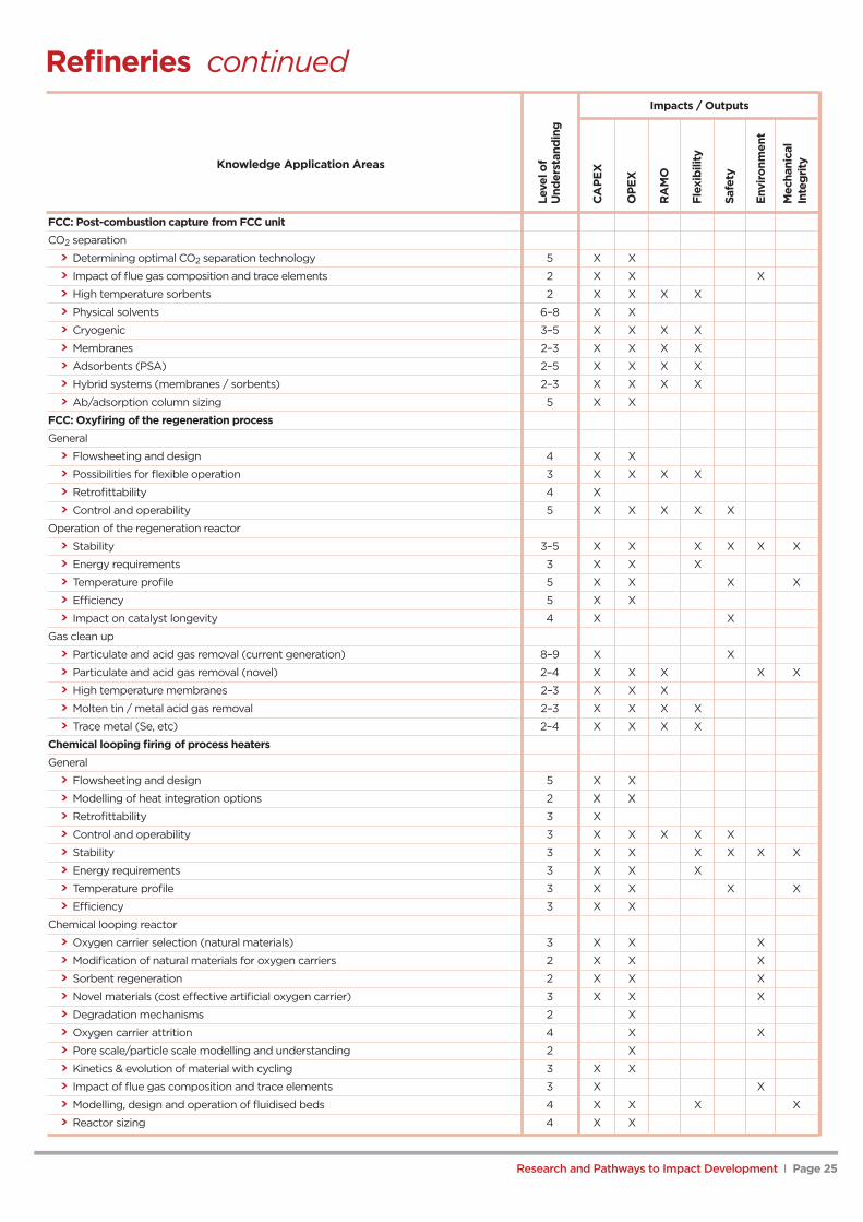
Refineries continuedImpacts / Outputs
FCC: Post-combustion capture from FCC unitCO2 separation
> Determining optimal CO2 separation technology 5 X X
> Impact of flue gas composition and trace elements 2 X X X
> High temperature sorbents 2 X X X X
> Physical solvents 6–8 X X
> Cryogenic 3–5 X X X X
> Membranes 2–3 X X X X
> Adsorbents (PSA) 2–5 X X X X
> Hybrid systems (membranes / sorbents) 2–3 X X X X
> Ab/adsorption column sizing 5 X X
FCC: Oxyfiring of the regeneration processGeneral
> Flowsheeting and design 4 X X
> Possibilities for flexible operation 3 X X X X
> Retrofittability 4 X
> Control and operability 5 X X X X X
Operation of the regeneration reactor
> Stability 3–5 X X X X X X
> Energy requirements 3 X X X
> Temperature profile 5 X X X X
> Efficiency 5 X X
> Impact on catalyst longevity 4 X X
Gas clean up
> Particulate and acid gas removal (current generation) 8–9 X X
> Particulate and acid gas removal (novel) 2–4 X X X X X
> High temperature membranes 2–3 X X X
> Molten tin / metal acid gas removal 2–3 X X X X
> Trace metal (Se, etc) 2–4 X X X X
Chemical looping firing of process heatersGeneral
> Flowsheeting and design 5 X X
> Modelling of heat integration options 2 XX XX
> Retrofittability 3 X
> Control and operability 3 X X X X X
> Stability 3 X X X X X X
> Energy requirements 3 X X X
> Temperature profile 3 X X X X
> Efficiency 3 X X
Chemical looping reactor
> Oxygen carrier selection (natural materials) 3 X X X
> Modification of natural materials for oxygen carriers 2 X X X
> Sorbent regeneration 2 X X X
> Novel materials (cost effective artificial oxygen carrier) 3 X X X
> Degradation mechanisms 2 X
> Oxygen carrier attrition 4 X X
> Pore scale/particle scale modelling and understanding 2 X
> Kinetics & evolution of material with cycling 3 X X
> Impact of flue gas composition and trace elements 3 X X
> Modelling, design and operation of fluidised beds 4 X X X X
> Reactor sizing 4 X X
Leve
lof
Und
erst
andi
ng
CA
PEx
OPE
x
RA
MO
Flex
ibili
ty
Safe
ty
Envi
ronm
ent
Mec
hani
cal
Inte
grityKnowledge Application Areas
Research and Pathways to Impact Development I Page 26
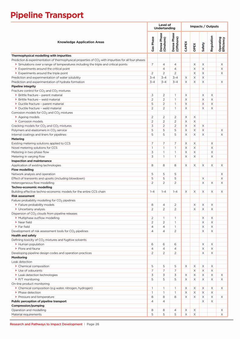
Pipeline TransportLevel of
Undertanding
Thermophysical modelling with impuritiesPrediction & experimentation of thermophysical properties of CO2 with impurities for all four phases
> Simulations over a range of temperatures including the triple and critical points 7 4 4 X X X> Experiments around the critical point 4 4 X X X> Experiments around the triple point 2 2 2 X X X
Prediction and experimentation of water solubility 3–4 3–4 3–4 X X XPrediction and experimentation of hydrate formation 3–4 3–4 3–4 X X X XPipeline integrityFracture control for CO2 and CO2 mixtures
> Brittle fracture – parent material 3 2 1 X X X> Brittle fracture – weld material 2 2 1 X X X> Ductile fracture – parent material 5 2 1 X X X> Ductile fracture – weld material 2 2 1 X X X
Corrosion models for CO2 and CO2 mixtures> Ageing models 2 2 2 X X> Corrosion models 2 2 2 X X
Cracking models for CO2 and CO2 mixtures 3 2 2 X X XPolymers and elastomers in CO2 service 5 5 5 X X X XInternal coatings and liners for pipelines 5 5 5 X X X XMeteringExisting metering solutions applied to CCS 7 7 7 X X XNovel metering solutions for CCS 1 1 1 X X XMetering in two phase flow 3 1 1 X X XMetering in varying flow 3 1 1 X X XInspection and maintenanceApplication of existing technologies 8 8 8 X X X X XFlow modellingNetwork analysis and operation 5 5 5 XEffect of transients and upsets (including blowdown) 5 5 5 X XHeterogeneous flow modelling 2 2 2 X X XTechno-economic modellingBuilding effective techno-economic models for the entire CCS chain 1–4 1–4 1–4 X X X X XRisk assessmentFailure probability modelling for CO2 pipelines
> Failure probability models 8 4 2 X X X> Uncertainy analysis 2 2 2 X X X
Dispersion of CO2 clouds from pipeline releases> Multiphase outflow modelling 2 1 1 X X> Near field 2 2 1 X X> Far field 4 4 1 X X
Development of risk assessment tools for CO2 pipelines 4 4 2 X XHealth and safetyDefining toxicity of CO2 mixtures and fugitive solvents
> Human population 6 6 6 X X> Flora and fauna 4 4 4 X X
Developing pipeline design codes and operation practices 2 2 2 X XMonitoringLeak detection
> Chemical composition 5 5 5 X X X X> Use of odourants 7 7 7 X X X> Leak detection technologies 3 3 3 X X X X X> P/T monitoring 5 5 5 X X X X X
On-line product monitoring> Chemical composition (e.g water, nitrogen, hydrogen) 1 1 1 X X X X X> Phase detection 1 1 1 X X X X> Pressure and temperature 8 8 8 X X X X X
Public perception of pipeline transport 4 4 X XCompression/pumpingOperation and modelling 8 8 4 X X XMaterial requirements 5 5 5 X X X
Gas
Phas
e
Den
sePh
ase
(Ons
hore
)
Den
sePh
ase
(Off
shor
e)
CA
PEx
OPE
x
Safe
ty
Reg
ulat
ion
Ope
ratin
gEffi
cien
cy
Knowledge Application Areas
Impacts / Outputs

Research and Pathways to Impact Development I Page 27
Shipping TransportLevel of
Understanding
Thermophysical modelling with impurities
Prediction and experimentation of thermophysical properties 3 3 X X X
Prediction and experimentation of water solubility 2 2 X X X
Prediction and experimentation of hydrate formation 3 3 X X X X
Metering
Existing metering solutions applied to CCS 8 8 X X X
Novel metering solutions for CCS 8 8 X X X
Inspection and maintenance
Application of existing technologies 7 7 X X X X X
Development of new technologies 4 4 X X X X X
Network modelling
Logistical models for ship based transportation 3 3 X X
Techno-economic modelling
Building effective assessment methodologies for the entire CCS chain 3 3 X X
Risk assessment
Failure probability modelling for ships 2 2 X X
Dispersion of CO2 clouds from ships 1 1 X X X X
Consequence modelling for ships 2 2 X X
Defining risk assessment tools for CO2 transportation by ship 1 1 X X X X
Health and safety
Defining toxicity 4 4 X X X
Transfer technologies
Onshore transfer 2 2 X X X X
Offshore transfer 2 2 X X X X
Inla
ndw
ater
way
s
Off
shor
e
CA
PEx
OPE
x
Safe
ty
Reg
ulat
ion
Syst
emEffi
cien
cy
Impacts / Outputs
Knowledge Application Areas

Research and Pathways to Impact Development I Page 28
Storage Issues (Aquifer and Depleted Fields)Impacts / Outputs
Static modelling
Storage capacity estimation – methodologies 7 X X X X X
Pore-space management and conflicts
Stacked reservoirs 6 X X X
Storage site footprint interactions (deep, shallow, seabed) 6 X X X
Pressure evolution X X X X
Water displacement 7 X X X X X X X X
Water flow through/along faults 5 X X X X
Water flow through caprock 6 X X X
Transfer of potable aquifer performance 7 X X
Depleted reservoir issues (Joule-Thompson etc.) 7 X X X X
Caprock integrity and migration pathways
Flow along faults (including stress/pressure effects) 5 X X X X X X X X
Flow along geological heterogeneities 5 X X X X X X
Stability under 'inflation' 4 X X X
Geological heterogeneity
Overburden characterisation and data requirements 5 X X X
High permeability pathways 6 X X X X X
Topseal relief/rugosity 5 X X X
Reservoir connectivity X X X
Migration and trapping processes
Capillary processes 6 X X X X X
Dissolution processes 5 X X X X X
Diffusion/convection 4 X X X X X X
Mineralisation 5 X X X X X X
Flow assurance (injectivity)
Hydrates in/near wellbore 6 X
Salinity effects (salting out) 8 X
Biofilms 3 X
Wellbore integrity
Long-term corrosion processes 7 X X X X
Mechanical effects at wellbore/rock interface 5 X X
Real field examples / samples 5 X X X
Downhole chemistry and interactions between CO2 and well materials, 7 Xnew and legacy, including wellbore, casing, chokes, ESPs etc.
Deep-focussed monitoring
Between-well imaging 5 X X X X X
Quantification in the reservoir 4 X X X X
Overburden leak detection 5 X X X X X X
Predictive seismicity 4 X X X X
Improved tracers 6 X X X X
Shallow-focussed monitoring
Baseline monitoring (establishing natural variation atnear-surface/seabed and water-column) 6 X X X X X X
Leakage detection at seabed/surface 6 X X X X X
Quantification in the shallow subsurface and emissions measurement 4 X X X
Leve
lof
Und
erst
andi
ng
Stor
age
Effici
ency
Ope
ratio
nal
Inte
grity
Stor
age
Foot
prin
t
Perf
orm
ance
Pred
ictio
n
Leak
age
Det
ectio
n
Mon
itorin
gC
osts
Tran
sfer
ofLi
abili
ty
Emis
sion
sM
easu
rem
ent
Add
ition
alH
CR
ecov
ery
Use
rCon
flict
s
Publ
icPe
rcep
tion
Lice
nsin
gan
dLe
asin
g
Reg
ulat
ion
Knowledge Application Areas
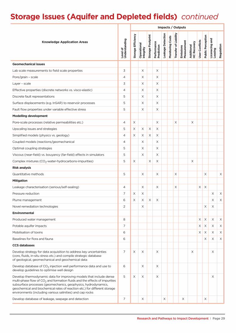
Storage Issues (Aquifer and Depleted fields) continuedImpacts / Outputs
Geomechanical issues
Lab scale measurements to field scale properties 3 X X
Pore/grain – scale 4 X X
Layer – scale 3 X X
Effective properties (discrete networks vs. visco-elastic) 4 X X
Discrete fault representations 5 X X
Surface displacements (e.g. InSAR) to reservoir processes 5 X X
Fault flow properties under variable effective stress 5 X X
Modelling development
Pore-scale processes (relative permeabilities etc.) 4 X X X X
Upscaling issues and strategies 5 X X X X
Simplified models (physics vs. geology) 4 X X X X
Coupled models (reactions/geomechanical 4 X X
Optimal coupling strategies 5 X X
Viscous (near-field) vs. bouyancy (far-field) effects in simulators 5 X X
Complex mixtures (CO2-water-hydrocarbons-impurities) 5 X X X X
Risk analysis
Quantitative methods 5 X X X X X
Mitigation
Leakage characterisation (serious/self-sealing) 4 X X X X X
Pressure reduction 7 X X X X
Plume management 6 X X X X X X
Novel remediation technologies 2 X X X
Environmental
Produced water management 8 X X X X
Potable aquifer impacts 7 X X X X
Mobilisation of toxins 6 X X X X
Baselines for flora and fauna 6 X X X
CCS databases
Develop strategy for data acquisition to address key uncertainties 7 X X X X X(core, fluids, in-situ stress etc.) and compile strategic databaseof geological, geomechanical and geochemical data
Develop database of CO2 injection well performance data and use to 6 X Xdevelop guidelines to optimise well design
Develop thermodynamic data for improving models that include dense 5 X X X Xmulti-phase flow of CO2 and formation fluids and the effects of impuritiessubsurface processes (geomechanics, geophysics, hydrodynamics,geochemical and biochemical rates of reaction etc.) for different storageenvironments (including various salinities) and cap rocks
Develop database of leakage, seepage and detection 7 X X X X
Leve
lof
Und
erst
andi
ng
Stor
age
Effici
ency
Ope
ratio
nal
Inte
grity
Stor
age
Foot
prin
t
Perf
orm
ance
Pred
ictio
n
Leak
age
Det
ectio
n
Mon
itorin
gC
osts
Tran
sfer
ofLi
abili
ty
Emis
sion
sM
easu
rem
ent
Add
ition
alH
CR
ecov
ery
Use
rCon
flict
s
Publ
icPe
rcep
tion
Lice
neci
ngan
dLe
asin
g
Reg
ulat
ion
Research and Pathways to Impact Development I Page 29
Knowledge Application Areas
Research and Pathways to Impact Development I Page 30
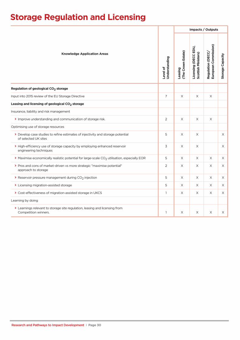
Storage Regulation and LicensingImpacts / Outputs
Regulation of geological CO2 storage
Input into 2015 review of the EU Storage Directive 7 X X X
Leasing and licensing of geological CO2 storage
Insurance, liability and risk management
> Improve understanding and communication of storage risk. 2 X X X
Optimising use of storage resources
> Develop case studies to refine estimates of injectivity and storage potential 5 X X Xof selected UK sites
> High-efficiency use of storage capacity by employing enhanced reservoir 3 X X Xengineering techniques
> Maximise economically realistic potential for large-scale CO2 utilisation, especially EOR 5 X X X X
> Pros and cons of market-driven vs more strategic "maximise potential" 2 X X X Xapproach to storage
> Reservoir pressure management during CO2 injection 5 X X X X
> Licensing migration-assisted storage 5 X X X X
> Cost-effectiveness of migration-assisted storage in UKCS 1 X X X X
Learning by doing
> Learnings relevant to storage site regulation, leasing and licensing fromCompetition winners. 1 X X X X
Leve
lof
Und
erst
andi
ng
Leas
ing
(The
Cro
wn
Esta
te)
Lice
nsin
g(D
ECC
EDU
,Sc
ottis
hM
inis
ters
)
Reg
ulat
ion
(DEC
C/
Euro
pean
Com
mis
sion
)
Stor
age
Cap
acity
Knowledge Application Areas
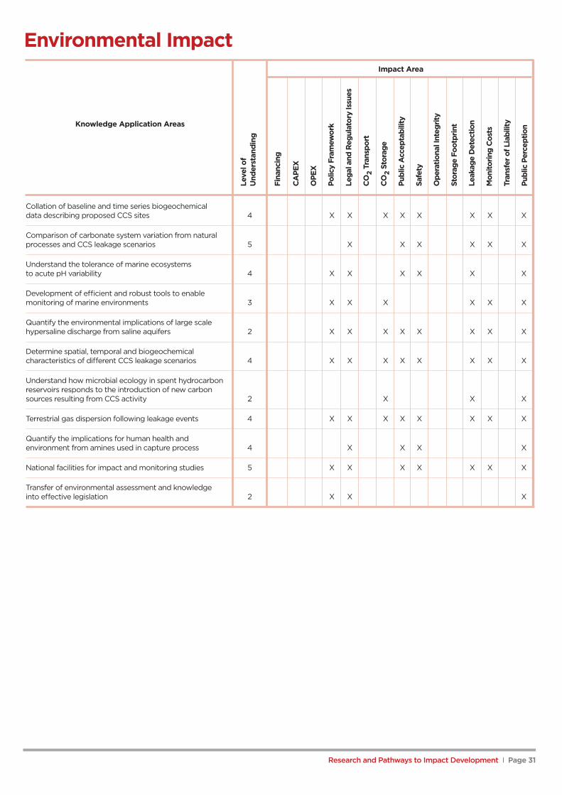
Environmental ImpactImpact Area
Collation of baseline and time series biogeochemicaldata describing proposed CCS sites 4 X X X X X X X X
Comparison of carbonate system variation from naturalprocesses and CCS leakage scenarios 5 X X X X X X
Understand the tolerance of marine ecosystemsto acute pH variability 4 X X X X X X
Development of efficient and robust tools to enablemonitoring of marine environments 3 X X X X X X
Quantify the environmental implications of large scalehypersaline discharge from saline aquifers 2 X X X X X X X X
Determine spatial, temporal and biogeochemicalcharacteristics of different CCS leakage scenarios 4 X X X X X X X X
Understand how microbial ecology in spent hydrocarbonreservoirs responds to the introduction of new carbonsources resulting from CCS activity 2 X X X
Terrestrial gas dispersion following leakage events 4 X X X X X X X X
Quantify the implications for human health andenvironment from amines used in capture process 4 X X X X
National facilities for impact and monitoring studies 5 X X X X X X X
Transfer of environmental assessment and knowledgeinto effective legislation 2 X X X
Leve
lof
Und
erst
andi
ng
Fina
ncin
g
CA
PEx
OPE
x
Polic
yFr
amew
ork
Lega
land
Reg
ulat
ory
Issu
es
CO
2Tr
ansp
ort
CO
2St
orag
e
Publ
icA
ccep
tabi
lity
Safe
ty
Ope
ratio
nalI
nteg
rity
Stor
age
Foot
prin
t
Leak
age
Det
ectio
n
Mon
itorin
gC
osts
Tran
sfer
ofLi
abili
ty
Publ
icPe
rcep
tion
Research and Pathways to Impact Development I Page 31
Knowledge Application Areas
Research and Pathways to Impact Development I Page 32
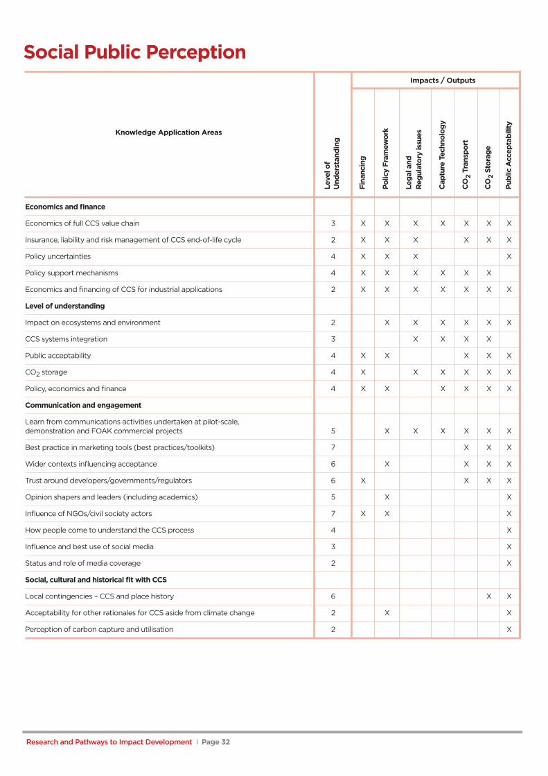
Social Public PerceptionImpacts / Outputs
Economics and finance
Economics of full CCS value chain 3 X X X X X X X
Insurance, liability and risk management of CCS end-of-life cycle 2 X X X X X X
Policy uncertainties 4 X X X X
Policy support mechanisms 4 X X X X X X
Economics and financing of CCS for industrial applications 2 X X X X X X X
Level of understanding
Impact on ecosystems and environment 2 X X X X X X
CCS systems integration 3 X X X X
Public acceptability 4 X X X X X
CO2 storage 4 X X X X X X
Policy, economics and finance 4 X X X X X X
Communication and engagement
Learn from communications activities undertaken at pilot-scale,demonstration and FOAK commercial projects 5 X X X X X X
Best practice in marketing tools (best practices/toolkits) 7 X X X
Wider contexts influencing acceptance 6 X X X X
Trust around developers/governments/regulators 6 X X X X
Opinion shapers and leaders (including academics) 5 X X
Influence of NGOs/civil society actors 7 X X X
How people come to understand the CCS process 4 X
Influence and best use of social media 3 X
Status and role of media coverage 2 X
Social, cultural and historical fit with CCS
Local contingencies – CCS and place history 6 X X
Acceptability for other rationales for CCS aside from climate change 2 X X
Perception of carbon capture and utilisation 2 X
Leve
lof
Und
erst
andi
ng
Fina
ncin
g
Polic
yFr
amew
ork
Lega
land
Reg
ulat
ory
issu
es
Cap
ture
Tech
nolo
gy
CO
2Tr
ansp
ort
CO
2St
orag
e
Publ
icA
ccep
tabi
lity
Knowledge Application Areas

Research and Pathways to Impact Development I Page 33
Economics and FinanceImpacts / Outputs
Project finance and innovative financial schemes and mechanisms 4 X X X X X X X X X
Financial strategies and valuation approaches appropriate for CCS 5 X X X X
Insurance and risk management during CCS development 3 X X X X X X X Xand operational phases
Insurance and risk management of end of CCS life cycle 2 X X X X X X X X X(e.g. decommissioning, dismantling and removing processequipment, on-going storage monitoring, long-termliability/stewardship – 10-30 years after injection ceases etc)
Project and systems integration 5 X X X X X X
Allocation of public funding for CCS research 4 X X X X(e.g. to drive down the cost of CO2 capture)
Economics of CCS RD&D and innovation 3 X X X X X X X
Economics and financing of CCS for industrial applications 7 X X X X X(steel, cement and fertilizer production, natural gas processing etc.)
Economics of the whole CCS value chain 2 X X X X X X X X
Economics of CCS hubs or clusters 5 X X X X X X X X X
Policy support mechanisms 5 X X X X X
Policy uncertainties associated with regulation, taxation and energy 5 X X X X X X
Economics and regulation of CO2 pipelines 5 X X X X X Xand storage (e.g. access, tariff setting, etc.)
CO2 for enhanced oil and gas recovery and 6 X X X X X Xcoal bed methane production
Utilisation of CO2 for other applications (minerals, chemicals) 5 X X X
Industrial policy and macroeconomic issues related to CCS 3 X X X X X X(impact on national competitiveness etc.)
CCS business models 4 X X X X X X X X
Leve
lof
Und
erst
andi
ng
Fina
ncin
g
Polic
yFr
amew
ork
Lega
land
Reg
ulat
ory
Issu
es
Cap
ture
Tech
nolo
gy
CO
2Tr
ansp
ort
CO
2St
orag
e
Publ
icA
ccep
tabi
lity
Safe
ty
CC
SR
elat
edIn
fras
truc
ture
Knowledge Application Areas

Research and Pathways to Impact Development I Page 34
CO2 and Related Substance PropertiesImpact Area
Capture
Post
> Amine solvent capture 6 X X X
> Novel solvents 3 X X X
> Absorber design 6 X X X
> Solvent degradation 4 X
Pre
> CO2 / syngas at low temperature 6 X X
Oxy
> Flue gas cleanup 5 X
> Sour-gas compression 5 X X
Transport
Pipeline
> Effect of impurities 6 X X
> Metering 5 X X
Storage
Aquifer
> Near well bore and reactive transport 6 X X X
> Structural trapping 6 X X X
> Capillary and solubility trapping 5 X X X
Hydrocarbon
> Near well bore and reactive transport 6 X X
> Structural trapping 6 X X X
> Capillary and solubility trapping 5 X X X
> Asphaltene precip. 5 X X
Leve
lof
Und
erst
andi
ng
VLE
/The
rmo
Prop
ertie
s
Tran
spor
tPro
pert
ies
Inte
rfac
ialP
rope
rtie
s
Che
mic
alPr
oper
ties
Knowledge Application Areas

Research and Pathways to Impact Development I Page 35
AP
PE
ND
IX1

Appendix 1The UK Carbon Capture and Storage Research Centre(Also see www.ukccsrc.ac.uk)
The UKCCSRC brings together over 200 of the UK’s world-class CCS academics toprovide a national focal point for CCS research and development. The Centre is a virtualnetwork where academics, industry, regulators and others in the sector collaborate toanalyse problems devise and carry out world-leading research and share delivery, thusmaximising impact. A key priority is supporting the UK economy by driving anintegrated research programme and building research capacity that is focused onmaximising the contribution of CCS to a low-carbon energy system for the UK.
Engagement with the Centre is also open to non-academics with a professional interestin CCS and these individuals are Associate Members.
The Centre also coordinates the CCS Community Network. The CCS CommunityNetwork is a collective of over 1,000 engineering, technological, natural, environmental,social and economic members with CCS interests. Network members span academia,industry, governmental and NGO sectors, and they all contribute to this diverse andvibrant community.
The UKCCSRC mission will be delivered through three key areas:
Delivering Impact
Research will be linked to a number of potential pathways to impact in future stagesof CCS deployment including:
Maximise the benefit of the DECC CCS demonstration programme, and in particulardevelop research in areas that can help to reduce the costs and risks of both first andsubsequent CCS projects.
Develop a knowledge base for the rollout of CCS.
Prepare for deployment of CCS to meet UK and EU 2050 targets, including industrialapplications, very low emissions from fossil fuels and negative emissions from biomassand other air capture with CCS.
Developing Leaders
The UKCCSRC transcends institutional and disciplinary boundaries and brings togethervisionary leaders who are able to set national and international multi-discipline andmedium-timescale research agendas. The UKCCSRC mentors inspirational team leadersto act as role models on complex, long-term research programmes, and provideleadership opportunities for early- and mid-career researchers. For further informationabout plans in your area of interest and/or to suggest potential projects, please contactthe relevant research area champion on the people page or, the UKCCSRC Secretariatat [email protected], or complete the online form on the membership page.
Research and Pathways to Impact Development I Page 36

Shaping Capability
The UKCCSRC provides CCS researchers with the continuity, support and opportunitiesto foster creativity and empower delivery of the highest quality long-term research inareas where there is current or future national need. The UKCCSRC is focused onmultidisciplinary research that can grow over time, enhance national capacity, and actas a focal point for international engagement. As part of shaping the capability of theUK to develop and rollout CCS the UKCCSRC will look to:
Actively seek support for fundamental and multidisciplinary CCS research, which canhave positive economic and social outcomes, from funders and sponsors in engineeringand natural sciences in collaboration with the environmental, biological, physical,chemical, economic and social sciences. These may be RCUK, government or industry.
Build strategic national and international research partnerships with industry and otheruser organisations to co-fund and co-deliver a range of R&D impacts linked to thegrowing opportunities for commercial deployment of CCS, in particular reducing costs,improving performance and minimising risks for future generations of CCS projects.
Lead on international scientific engagement in CCS, exploiting existing major links withthe rest of Europe, North America, China and India, and developing interactions withother major potential CCS users in the Middle East, Africa and South America.
StructureThe activities of the UKCCSRC will be overseen by an independent Board made up ofEPSRC (Engineering and Physical Sciences Research Council) and DECC (Departmentof Energy and Climate Change) representatives and of seven eminent and highlyregarded individuals from CCS stakeholder groupings, appointed by, and reporting to,EPSRC. The Board will also act as an independent panel for final adjudication onallocations of funding for research from the UKCCSRC’s RCUK grant. A ManagementTeam (MT) made up of the Principal Investigator (PI), and eight Co-Investigators (CoIs)with thematic responsibilities, plus a Secretariat, will be responsible for running theCentre. In addition to operating the current grant, key elements of the MT’s role,supported by the other Research Area Champions, will be ensuring the scientificauthority, relevance, expansion and longer-term sustainability of the UKCCSRC.The Centre's Management Team also works with the Independent Advisory Panel (IAP)to develop a shared vision for effective industrial engagement, forward planning anddelivery mechanisms. The IAP is appointed by the UKCCSRC Coordination Group, andits members act in a personal capacity. IAP membership is comprised of approximately20 individuals from CCS stakeholder groupings, with approximately three quartersbeing from a range of industrial organisations (but all acting in a personal capacity).
1.2 Funded Research Programme
The UKCCSRC has £4.5 million in flexible funding to use to support CCS research.The first call (Call 1) for proposals was launched in last quarter of 2012 and as a result,the Centre offered funding to 13 research projects totalling £2.2 million. A second call(Call 2) for funding was issued in the first quarter of 2014 and as a result, the Centreoffered funding to 14 research proposals totalling £2.57 million.
Research and Pathways to Impact Development I Page 37
1.3 Research and Pathways to Impact Delivery (RAPID)
For UKCCSRC to be truly successful at delivering impact, the key is to linkworld-leading research with impact from the outset. While serendipitous outcomesmay arise, research on challenges linked to CCS deployment must include plausibleroutes to delivering a positive impact.
The UKCCSRC has access to a wealth of talent and experience amongst its members,associates, network members, stakeholders and advisory groups. This expertise allowsthe Centre to analyse challenges for CCS deployment (both in terms of research andimpact delivery), which can only be dealt with in aggregate by multidisciplinary teamsof leading researchers that have built up know-how from working together and withkey stakeholders.
In all cases, the UKCCSRC will assess whether the research and/or the impact canbest be carried out in partnership with other organisations, including partnershipwith funders. The same partners could be involved in both research and impact.The UKCCSRC will have a much greater profile and research assets than individualmembers and as a whole will be seen as a valuable partner, to join and to invite intoother collaborative research partnerships (in Europe and globally).
The RAPID process will run throughout the course of the UKCCSRC with resultssummarised in a RAPID Handbook which will be periodically updated throughoutthe course of the UKCCSRC grant.
Research and Pathways to Impact Development I Page 38


www.ukccsrc.ac.uk
UK Carbon Capture and Storage Research CentreSanderson Building, The King’s BuildingsMayfield Road, Edinburgh, EH9 3FBT +44 (0) 131 650 8564E [email protected]